EP1572393B1 - Split die for forming grooved workpieces - Google Patents
Split die for forming grooved workpieces Download PDFInfo
- Publication number
- EP1572393B1 EP1572393B1 EP03720706A EP03720706A EP1572393B1 EP 1572393 B1 EP1572393 B1 EP 1572393B1 EP 03720706 A EP03720706 A EP 03720706A EP 03720706 A EP03720706 A EP 03720706A EP 1572393 B1 EP1572393 B1 EP 1572393B1
- Authority
- EP
- European Patent Office
- Prior art keywords
- blank
- external
- tubular wall
- wall face
- grooves
- Prior art date
- Legal status (The legal status is an assumption and is not a legal conclusion. Google has not performed a legal analysis and makes no representation as to the accuracy of the status listed.)
- Expired - Lifetime
Links
Images







Classifications
-
- B—PERFORMING OPERATIONS; TRANSPORTING
- B21—MECHANICAL METAL-WORKING WITHOUT ESSENTIALLY REMOVING MATERIAL; PUNCHING METAL
- B21K—MAKING FORGED OR PRESSED METAL PRODUCTS, e.g. HORSE-SHOES, RIVETS, BOLTS OR WHEELS
- B21K1/00—Making machine elements
- B21K1/56—Making machine elements screw-threaded elements
-
- B—PERFORMING OPERATIONS; TRANSPORTING
- B21—MECHANICAL METAL-WORKING WITHOUT ESSENTIALLY REMOVING MATERIAL; PUNCHING METAL
- B21K—MAKING FORGED OR PRESSED METAL PRODUCTS, e.g. HORSE-SHOES, RIVETS, BOLTS OR WHEELS
- B21K1/00—Making machine elements
- B21K1/58—Making machine elements rivets
- B21K1/60—Making machine elements rivets hollow or semi-hollow rivets
-
- B—PERFORMING OPERATIONS; TRANSPORTING
- B21—MECHANICAL METAL-WORKING WITHOUT ESSENTIALLY REMOVING MATERIAL; PUNCHING METAL
- B21C—MANUFACTURE OF METAL SHEETS, WIRE, RODS, TUBES, PROFILES OR LIKE SEMI-MANUFACTURED PRODUCTS OTHERWISE THAN BY ROLLING; AUXILIARY OPERATIONS USED IN CONNECTION WITH METAL-WORKING WITHOUT ESSENTIALLY REMOVING MATERIAL
- B21C37/00—Manufacture of metal sheets, rods, wire, tubes, profiles or like semi-manufactured products, not otherwise provided for; Manufacture of tubes of special shape
- B21C37/06—Manufacture of metal sheets, rods, wire, tubes, profiles or like semi-manufactured products, not otherwise provided for; Manufacture of tubes of special shape of tubes or metal hoses; Combined procedures for making tubes, e.g. for making multi-wall tubes
- B21C37/15—Making tubes of special shape; Making tube fittings
- B21C37/20—Making helical or similar guides in or on tubes without removing material, e.g. by drawing same over mandrels, by pushing same through dies ; Making tubes with angled walls, ribbed tubes or tubes with decorated walls
-
- B—PERFORMING OPERATIONS; TRANSPORTING
- B21—MECHANICAL METAL-WORKING WITHOUT ESSENTIALLY REMOVING MATERIAL; PUNCHING METAL
- B21C—MANUFACTURE OF METAL SHEETS, WIRE, RODS, TUBES, PROFILES OR LIKE SEMI-MANUFACTURED PRODUCTS OTHERWISE THAN BY ROLLING; AUXILIARY OPERATIONS USED IN CONNECTION WITH METAL-WORKING WITHOUT ESSENTIALLY REMOVING MATERIAL
- B21C37/00—Manufacture of metal sheets, rods, wire, tubes, profiles or like semi-manufactured products, not otherwise provided for; Manufacture of tubes of special shape
- B21C37/06—Manufacture of metal sheets, rods, wire, tubes, profiles or like semi-manufactured products, not otherwise provided for; Manufacture of tubes of special shape of tubes or metal hoses; Combined procedures for making tubes, e.g. for making multi-wall tubes
- B21C37/15—Making tubes of special shape; Making tube fittings
- B21C37/20—Making helical or similar guides in or on tubes without removing material, e.g. by drawing same over mandrels, by pushing same through dies ; Making tubes with angled walls, ribbed tubes or tubes with decorated walls
- B21C37/202—Making helical or similar guides in or on tubes without removing material, e.g. by drawing same over mandrels, by pushing same through dies ; Making tubes with angled walls, ribbed tubes or tubes with decorated walls with guides parallel to the tube axis
-
- B—PERFORMING OPERATIONS; TRANSPORTING
- B21—MECHANICAL METAL-WORKING WITHOUT ESSENTIALLY REMOVING MATERIAL; PUNCHING METAL
- B21C—MANUFACTURE OF METAL SHEETS, WIRE, RODS, TUBES, PROFILES OR LIKE SEMI-MANUFACTURED PRODUCTS OTHERWISE THAN BY ROLLING; AUXILIARY OPERATIONS USED IN CONNECTION WITH METAL-WORKING WITHOUT ESSENTIALLY REMOVING MATERIAL
- B21C37/00—Manufacture of metal sheets, rods, wire, tubes, profiles or like semi-manufactured products, not otherwise provided for; Manufacture of tubes of special shape
- B21C37/06—Manufacture of metal sheets, rods, wire, tubes, profiles or like semi-manufactured products, not otherwise provided for; Manufacture of tubes of special shape of tubes or metal hoses; Combined procedures for making tubes, e.g. for making multi-wall tubes
- B21C37/15—Making tubes of special shape; Making tube fittings
- B21C37/20—Making helical or similar guides in or on tubes without removing material, e.g. by drawing same over mandrels, by pushing same through dies ; Making tubes with angled walls, ribbed tubes or tubes with decorated walls
- B21C37/205—Making helical or similar guides in or on tubes without removing material, e.g. by drawing same over mandrels, by pushing same through dies ; Making tubes with angled walls, ribbed tubes or tubes with decorated walls with annular guides
-
- B—PERFORMING OPERATIONS; TRANSPORTING
- B21—MECHANICAL METAL-WORKING WITHOUT ESSENTIALLY REMOVING MATERIAL; PUNCHING METAL
- B21C—MANUFACTURE OF METAL SHEETS, WIRE, RODS, TUBES, PROFILES OR LIKE SEMI-MANUFACTURED PRODUCTS OTHERWISE THAN BY ROLLING; AUXILIARY OPERATIONS USED IN CONNECTION WITH METAL-WORKING WITHOUT ESSENTIALLY REMOVING MATERIAL
- B21C37/00—Manufacture of metal sheets, rods, wire, tubes, profiles or like semi-manufactured products, not otherwise provided for; Manufacture of tubes of special shape
- B21C37/06—Manufacture of metal sheets, rods, wire, tubes, profiles or like semi-manufactured products, not otherwise provided for; Manufacture of tubes of special shape of tubes or metal hoses; Combined procedures for making tubes, e.g. for making multi-wall tubes
- B21C37/15—Making tubes of special shape; Making tube fittings
- B21C37/20—Making helical or similar guides in or on tubes without removing material, e.g. by drawing same over mandrels, by pushing same through dies ; Making tubes with angled walls, ribbed tubes or tubes with decorated walls
- B21C37/207—Making helical or similar guides in or on tubes without removing material, e.g. by drawing same over mandrels, by pushing same through dies ; Making tubes with angled walls, ribbed tubes or tubes with decorated walls with helical guides
Definitions
- the invention relates to a method of forming a tubular fastener, and more particularly to a method of forming a radially expandable externally grooved tubular fastener from metal.
- Such fasteners are used to fasten together two or more workpieces by inserting a fastener in a suitable aperture through the workpieces, and radially expanding at least part of the tubular fastener so as to engage the workpieces.
- the tubular fastener is provided with a radially enlarged head at one end which contacts the face of the nearer workpiece.
- the fastener may engage all of the workpieces, or only the workpiece most remote from the head. Radial expansion of the tubular fastener may be achieved by pushing or pulling through its bore the head of a mandrel.
- the present invention aims to provide an improved and simplified method of forming such fasteners, needing few manufacturing operations.
- the invention provides a method of forming a radially expandable externally grooved tubular fastener from metal, as defined in claim 1 or 9. Further preferred features of the present invention are set out in claims 2 to 8.
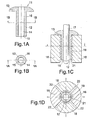
- Figures 1A and 1B show the blank used, Figure 1A being an axial section on the line 1A-1A of Figure 1B, and Figure 1B being a cross-section on the line 1B-1B of Figure 1A .
- the blank 11 has an elongated tubular body wall 12 with a radially enlarged head 13 (in a so-called "pan head” shape at one end).
- the blank has a cylindrical bore 14 extending throughout its entire length, to provide an internal tubular wall surface 15.
- the tubular wall 12 has a cylindrical outer surface wall 16.
- bore 14 and/or walls 12 and 15 may have non-cylindrical shapes such as tri-roundular or hexagonal shapes.
- the internal wall face 15 of the blank is supported on a cylindrical support pin 17 ( Figures 1C and 1D ) which is a close fit in the bore 14.
- the tubular wall 12 of the blank is then radially squeezed, as illustrated in Figures 1E and 1F , by forcing the four die members 18 radially inwardly towards the support pin 17, in the directions indicated by the arrows A in Figure 1F .
- the grooved faces of the die members engage the external wall surface 16 of the tubular body wall 12 of the blank, to deform it.
- the internal wall 15 of the blank is prevented from moving radially inwardly by the contact with the rigid support pin 17.
- the radially outer part of the body wall 12 is deformed so that it becomes substantially complementary in shape to the shape of the grooves 19 in the die members 18, so that the external surface wall 16 of the tubular body is formed with circumferential grooves 23 (see Figure 1G ).
- the four die members 18 are closed together only so far as to leave a reduced radial gap 22 between each and the next. These gaps accommodate, and help to form, protrusions 24 which project radially outwardly from the thread formed on the blank. These arise due to the squeezing action on the metal of the tubular wall 12, and are shown in Figure 1F . They are shown on an enlarged scale in Figure 1M (which is an enlargement of the part of Figure 1F indicated), and also in Figure 1L , which is an enlarged partial section on the line X-X of Figure 1F .
- the protrusions 24 are formed in the valleys of the grooves 23 on the wall of the blank and extend radially outwardly to slightly beyond the crests of the grooves. It will be appreciated that the protrusions 24 need not extend beyond the crests of the grooves 23.
- Figure 1N An alternative arrangement is illustrated in Figure 1N , which is an enlargement corresponding to Figure 1M .
- side walls of each die 18 are further apart, so that when the grooves 23 on the blank are fully formed, the adjacent walls of the dies 18 are in contact with each other, as illustrated in Figure 1N .
- a suitable space 25 is left adjacent the grooved faces of the dies, to accommodate the protrusions 24.
- the four dies are then drawn apart again, as illustrated in Figures 1G and 1H , with directions indicated by the arrows B in Figure 1H .
- the support pin 17 can then be withdrawn axially from between the dies, carrying the blank with it.
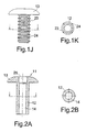
- the blank can then be pushed off the pin, to leave the formed blank as shown in Figures 1J and 1K .
- blade is used at this stage, as a matter of consistency and convenience. It may be that the tubular fastener has been fully manufactured at this stage.
- the grooved blank is subject to further manufacturing stages, for example heat treatment and/or surface treatment.
- FIG. 2A to 2K A second example of the method according to the invention is illustrated in Figures 2A to 2K , which as previously mentioned correspond to Figures 1A to 1K respectively, like parts being indicated by like reference numerals.
- This second method is generally similar to the first method, and may be considered as a modification thereof. Accordingly the second method will be described in detail only where it differs from the first.
- the head 13 of the blank 11 is formed with a counterbore 26.
- the end face 34 of support pin 17 ( Figure 2C ) is in contact with the end face 35 of expander pin 36 which is formed with expander part 27 or larger diameter, merging with the diameter of the support pin by a conical taper 28.
- the four dies 18 are initially closed together so that there are no radial gaps between their side faces, and their radially inner grooved surfaces provide a small gap with the external wall 16 of the tubular body wall 12 of the blank, as illustrated in Figures 2C and 2D .
- the support pin 17 is then pulled with respect to the blank, in the direction towards the head 13 of the blank, i.e. upwards as shown in Figure 2C .
- the taper 28 and then the expander portion 27 progressively enter the bore 14 of the blank.
- the blank is prevented from moving axially upwards by a support tool 29 which contacts the blank head 13 and which takes up the reaction force.
- the tubular body wall 12 is thus radially expanded, so that its outer part is squeezed into the grooves 19 in the die members, thus forming external circumferential grooves in the tubular wall.
- the counterbore 26 within the head 13 of the blank accommodates the expander portion 27, so that the head 13 is not radially expanded. This is the position illustrated in Figures 2E and 2F . Since there are no radial gaps between the dies 18, no protrusions from the grooved external face of the blank are formed.
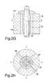
- the dies 18 are then withdrawn radially, as shown in Figures 2G and 2H , and the externally grooved blank is pushed off the expander section 27 to provide the result illustrated in Figures 2J and 2K .
- Protrusions may be formed by leaving radial gaps between the dies as for the first method described above.
- the third example method shown in Figures 3A to 3M may be considered as combining features of the first two methods, in that it combines an effective decrease in the diameter of engagement of the external die surfaces and an increase in the diameter of engagement of the internal support.
- the blank 11 is identical with that shown in Figures 2A and 2B and used on the second example method.
- the support pin 17 is joined by a taper 28 to an expander position 27 of enlarged diameter.
- the blank is placed on the support pin 17 and inserted between the grooved inner walls of the dies 18.
- the dies are then advanced radially inwardly to the position shown in Figures 3E and 3F , in which the ridges between the grooves in the dies partially enter the outer surface wall 16, as shown in Figures 3E and 3F , and more clearly in the enlargement in Figure 3L .
- the body wall 12 is supported against inward deformation by the support pin 17.
- the support pin 17 is then pushed axially upwards into the tubular blank, against the reaction of a support tool 29 contacting the head 13 of the blank, so that the expander portion 27 enters the bore of the tubular wall 12 and radially expands it.
- the outer part of the wall material is thus forced into the grooves in the dies, as illustrated in Figures 3G and 3H .
- the material may not completely fill the grooves in the dies.
- the material of the blank is aluminium 5052, containing 2.5% magnesium.
- the length of the tubular body or shank is 7.0mm, its external diameter is 3.4mm, the internal diameter of its bore is 1.6mm, the diameter of the head of 6.0mm, and the thickness of the head is 0.9mm. It will be noted that other materials and/or dimensions may be used.
- Figures 4A and 4B illustrate a fastener with a helical groove 31, which provides a screw-thread (which could be considered as comprising a number of circumferential or near-circumferential grooves joined together to form a helical groove).
- a screw-thread which could be considered as comprising a number of circumferential or near-circumferential grooves joined together to form a helical groove.
- Figures 5A and 5B Figures 6A and 6B illustrate a fastener with longitudinal grooves 32.
- the method of the present invention provides for the formation of a tubular fastener with grooves of all these, and other, configurations.
Landscapes
- Engineering & Computer Science (AREA)
- Mechanical Engineering (AREA)
- Forging (AREA)
- Superconductors And Manufacturing Methods Therefor (AREA)
- Shaping Metal By Deep-Drawing, Or The Like (AREA)
Abstract
Description
- The invention relates to a method of forming a tubular fastener, and more particularly to a method of forming a radially expandable externally grooved tubular fastener from metal.
- Such fasteners are used to fasten together two or more workpieces by inserting a fastener in a suitable aperture through the workpieces, and radially expanding at least part of the tubular fastener so as to engage the workpieces. Commonly the tubular fastener is provided with a radially enlarged head at one end which contacts the face of the nearer workpiece. In this case the fastener may engage all of the workpieces, or only the workpiece most remote from the head. Radial expansion of the tubular fastener may be achieved by pushing or pulling through its bore the head of a mandrel.
- Such fasteners and their method of installation are well-known in the mechanical assembly industry.
- The present invention aims to provide an improved and simplified method of forming such fasteners, needing few manufacturing operations.
- The invention provides a method of forming a radially expandable externally grooved tubular fastener from metal, as defined in claim 1 or 9. Further preferred features of the present invention are set out in claims 2 to 8.
- Some specific embodiments of the present invention will now be described by way of example and with reference to the accompanying drawings, in which:-
-
Figures 1A to 1N illustrate a first method; -
Figures 2A to 2K illustrate a second method; -
Figures 3A to 3M illustrate a third method; and -
Figures 4A and 4B ,5A and 5B, and 6A and 6B illustrate possible alternative groove configurations for a formed tubular fastener. - In
Figures 1 ,2 and3 , the individual figures suffixed "A", "B", "C" etc. through to "K" are, in general, corresponding views respectively on the three example methods. - Referring first to the method illustrated in
Figures 1A to 1N ,Figures 1A and 1B show the blank used,Figure 1A being an axial section on theline 1A-1A ofFigure 1B, and Figure 1B being a cross-section on theline 1B-1B ofFigure 1A . (Most of the remainder of the figures are also in such pairs, one of which is an axial section and the other of which is a cross-section, as is common in engineering drawing practice. Since the reader will be familiar with this, this relationship between the figures of each pair will not be further referred to). The blank 11 has an elongatedtubular body wall 12 with a radially enlarged head 13 (in a so-called "pan head" shape at one end). The blank has acylindrical bore 14 extending throughout its entire length, to provide an internaltubular wall surface 15. Thetubular wall 12 has a cylindricalouter surface wall 16. - It will be appreciated that the
bore 14 and/orwalls - The
internal wall face 15 of the blank is supported on a cylindrical support pin 17 (Figures 1C and 1D ) which is a close fit in thebore 14. - Outside the
tubular wall 12 there are then provided fourexternal die members 18 in the form of a split die. The blank is inserted between them so that (as shown inFigure 1C ) the underside of thehead 13 abuts one set of end faces of themembers 18, the other ends of which project beyond the tail end of thetubular wall 12 of the blank. The inner face of eachmember 18, which faces towards theexternal wall 16 of thebody 12, is formed withgrooves 19. Themembers 18 are initially spaced slightly apart, to provide aspace 21 into which thebody wall 12 of the blank can be introduced with clearance, as shown inFigures 1C and 1D . There is aradial gap 22 between adjacent diemembers 18. - The
tubular wall 12 of the blank is then radially squeezed, as illustrated inFigures 1E and 1F , by forcing the fourdie members 18 radially inwardly towards thesupport pin 17, in the directions indicated by the arrows A inFigure 1F . The grooved faces of the die members engage theexternal wall surface 16 of thetubular body wall 12 of the blank, to deform it. Theinternal wall 15 of the blank is prevented from moving radially inwardly by the contact with therigid support pin 17. The radially outer part of thebody wall 12 is deformed so that it becomes substantially complementary in shape to the shape of thegrooves 19 in thedie members 18, so that theexternal surface wall 16 of the tubular body is formed with circumferential grooves 23 (seeFigure 1G ). As shown inFigure 1F , the fourdie members 18 are closed together only so far as to leave a reducedradial gap 22 between each and the next. These gaps accommodate, and help to form,protrusions 24 which project radially outwardly from the thread formed on the blank. These arise due to the squeezing action on the metal of thetubular wall 12, and are shown inFigure 1F . They are shown on an enlarged scale inFigure 1M (which is an enlargement of the part ofFigure 1F indicated), and also inFigure 1L , which is an enlarged partial section on the line X-X ofFigure 1F . Theprotrusions 24 are formed in the valleys of thegrooves 23 on the wall of the blank and extend radially outwardly to slightly beyond the crests of the grooves. It will be appreciated that theprotrusions 24 need not extend beyond the crests of thegrooves 23. - An alternative arrangement is illustrated in
Figure 1N , which is an enlargement corresponding toFigure 1M . In this alternative, side walls of eachdie 18 are further apart, so that when thegrooves 23 on the blank are fully formed, the adjacent walls of thedies 18 are in contact with each other, as illustrated inFigure 1N . However, asuitable space 25 is left adjacent the grooved faces of the dies, to accommodate theprotrusions 24. - The four dies are then drawn apart again, as illustrated in
Figures 1G and 1H , with directions indicated by the arrows B inFigure 1H . This releases thegrooves 23 which have been formed on the external surface of thetubular body 11 from interengagement with thegrooves 19 in the die members. Thesupport pin 17 can then be withdrawn axially from between the dies, carrying the blank with it. The blank can then be pushed off the pin, to leave the formed blank as shown inFigures 1J and 1K . - The term "blank" is used at this stage, as a matter of consistency and convenience. It may be that the tubular fastener has been fully manufactured at this stage.
- Alternatively it may be that the grooved blank is subject to further manufacturing stages, for example heat treatment and/or surface treatment.
- A second example of the method according to the invention is illustrated in
Figures 2A to 2K , which as previously mentioned correspond toFigures 1A to 1K respectively, like parts being indicated by like reference numerals. This second method is generally similar to the first method, and may be considered as a modification thereof. Accordingly the second method will be described in detail only where it differs from the first. - As shown in
Figure 2A , thehead 13 of the blank 11 is formed with acounterbore 26. Theend face 34 of support pin 17 (Figure 2C ) is in contact with theend face 35 ofexpander pin 36 which is formed with expanderpart 27 or larger diameter, merging with the diameter of the support pin by aconical taper 28. The fourdies 18 are initially closed together so that there are no radial gaps between their side faces, and their radially inner grooved surfaces provide a small gap with theexternal wall 16 of thetubular body wall 12 of the blank, as illustrated inFigures 2C and 2D . Thesupport pin 17 is then pulled with respect to the blank, in the direction towards thehead 13 of the blank, i.e. upwards as shown inFigure 2C . Thetaper 28 and then theexpander portion 27 progressively enter thebore 14 of the blank. The blank is prevented from moving axially upwards by asupport tool 29 which contacts theblank head 13 and which takes up the reaction force. Thetubular body wall 12 is thus radially expanded, so that its outer part is squeezed into thegrooves 19 in the die members, thus forming external circumferential grooves in the tubular wall. Thecounterbore 26 within thehead 13 of the blank accommodates theexpander portion 27, so that thehead 13 is not radially expanded. This is the position illustrated inFigures 2E and 2F . Since there are no radial gaps between thedies 18, no protrusions from the grooved external face of the blank are formed. Thedies 18 are then withdrawn radially, as shown inFigures 2G and 2H , and the externally grooved blank is pushed off theexpander section 27 to provide the result illustrated inFigures 2J and 2K . Protrusions may be formed by leaving radial gaps between the dies as for the first method described above. - The third example method shown in
Figures 3A to 3M may be considered as combining features of the first two methods, in that it combines an effective decrease in the diameter of engagement of the external die surfaces and an increase in the diameter of engagement of the internal support. - As shown in
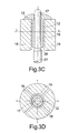
Figures 3A and 3B , the blank 11 is identical with that shown inFigures 2A and 2B and used on the second example method. Likewise thesupport pin 17 is joined by ataper 28 to anexpander position 27 of enlarged diameter. As shown inFigures 3C and 3D , initially the blank is placed on thesupport pin 17 and inserted between the grooved inner walls of the dies 18. The dies are then advanced radially inwardly to the position shown inFigures 3E and 3F , in which the ridges between the grooves in the dies partially enter theouter surface wall 16, as shown inFigures 3E and 3F , and more clearly in the enlargement inFigure 3L . Thebody wall 12 is supported against inward deformation by thesupport pin 17. Thesupport pin 17 is then pushed axially upwards into the tubular blank, against the reaction of asupport tool 29 contacting thehead 13 of the blank, so that theexpander portion 27 enters the bore of thetubular wall 12 and radially expands it. The outer part of the wall material is thus forced into the grooves in the dies, as illustrated inFigures 3G and 3H . As shown in enlargementFigure 3M , the material may not completely fill the grooves in the dies. - The dies are then withdrawn radially to release engagement with the blank, which is then pushed off the
expander portion 27 to provide the result illustrated inFigures 3J and 3K . As shown inFigure 3H , when the dies 18 are together, there areradial gaps 22 between them, so that-as shown inFigures 3J and 3K protrusions 24 are thrown up. - In the foregoing examples, the material of the blank is aluminium 5052, containing 2.5% magnesium. After forming, the length of the tubular body or shank is 7.0mm, its external diameter is 3.4mm, the internal diameter of its bore is 1.6mm, the diameter of the head of 6.0mm, and the thickness of the head is 0.9mm. It will be noted that other materials and/or dimensions may be used.
- The invention is not restricted to the details of the foregoing examples. For instance, by providing
grooves 19 of suitable form on the inner faces of thedie members 18, external grooves of the other desired configurations may be formed on the external tubular wall of the blank. Thus,Figures 4A and 4B illustrate a fastener with ahelical groove 31, which provides a screw-thread (which could be considered as comprising a number of circumferential or near-circumferential grooves joined together to form a helical groove). There may be an unthreadedportion 33 at one or both ends of the threaded portion. If such a helical thread were formed by the method of the first foregoing example, radial protrusions would be formed, which would provide resistance to unscrewing the installed fastener. This is illustrated inFigures 5A and 5B Figures 6A and 6B illustrate a fastener withlongitudinal grooves 32. The method of the present invention provides for the formation of a tubular fastener with grooves of all these, and other, configurations.
Claims (9)
- A method of forming a radially expandable externally grooved tubular fastener from metal, comprising the steps of:-providing a suitable tubular blank having a tubular wall;and squeezing the tubular wall between an internal member with a surface which engages the internal tubular wall face of the blank and a plurality of external members provided with suitably shaped surfaces engaging the external tubular wall face of the blank;thereby to form grooves on the external tubular wall face of the blank;in which the squeezing is achieved by the effective decrease in diameter of the external members which are engaged with the external tubular wall face of the blank, and in which the external members are closed on to the external wall face of the tubular blank to form grooves thereon and then remain in the same spatial relationship with each other until they are withdrawn to release the blank;
in which the external members when closed on to the external tubular wall face of the blank form grooves thereon and also form a plurality of radially extending protrusions thereon;
and in which the external members are closed on to the external tubular wall face of the blank so as to leave a space between each member and the next, thereby to accommodate the protrusions from the grooves. - A method as claimed in claim 1, in which the squeezing is achieved by both the effective increase in diameter of the engagement of the internal tubular member with the internal tubular wall face of the blank and the effective decrease in the diameter of engagement of the suitably shaped surfaces of the external members with the external tubular wall face of the blank.
- A method as claimed in claim 2, in which opposed walls of adjacent external members which define the spaces between them also assist in forming the protrusions.
- A method as claimed in claim 2, in which the external members are first progressively closed on to the external tubular wall face of the blank so as to engage it and at least partially form grooves in it, and the internal member engages the internal tubular wall face of the blank with an increasing diameter, thereby to assist in the formation of the grooves.
- A method as claimed in claim 2, in which the internal member has an external diameter which varies along its length, and is moved axially with respect to the tubular blank thereby to increase the diameter which engages the internal tubular wall face of the blank as aforesaid.
- A method as claimed in any of claims 1 to 5, in which the grooves on the external tubular wall face of the blank are in the form of circumferential grooves.
- A method as claimed in any of claims 1 to 5, in which the grooves on the external tubular wall face of the blank are in the form of a screw thread.
- A method as claimed in any of claims 1 to 5, in which the grooves on the external tubular wall of the blank are in the form of longitudinal grooves.
- A method of forming a radially expandable externally grooved tubular fastener from metal, comprising the steps of:-providing a suitable tubular blank having a tubular wall;and squeezing the tubular wall between an internal member with a surface which engages the internal tubular wall face of the blank and a plurality of external members provided with suitably shaped surfaces engaging the external tubular wall face of the blank;thereby to form grooves on the external tubular wall face of the blank;in which the internal member engages the internal tubular wall of the blank at an unchanging diameter, and the external members are progressively closed on to the external wall face of the tubular blank to form grooves thereon and are then withdrawn form engagement with the external tubular wall face of the blank thereby to release the grooved blank,
wherein the external members when closed on to the external tubular wall face of the blank form grooves thereon and also form a plurality of radially extending protrusions thereon,
and in which the external members are closed on to the external tubular wall face of blank so as to leave a space between each member and the next, thereby to accommodate the protrusions from the grooves.
Applications Claiming Priority (3)
| Application Number | Priority Date | Filing Date | Title |
|---|---|---|---|
| GB0214959 | 2002-06-28 | ||
| GB0214959A GB2390047B (en) | 2002-06-28 | 2002-06-28 | Split die groove maker |
| PCT/GB2003/001619 WO2004002652A1 (en) | 2002-06-28 | 2003-04-15 | Split die for forming grooved workpieces |
Publications (2)
| Publication Number | Publication Date |
|---|---|
| EP1572393A1 EP1572393A1 (en) | 2005-09-14 |
| EP1572393B1 true EP1572393B1 (en) | 2008-12-17 |
Family
ID=9939461
Family Applications (1)
| Application Number | Title | Priority Date | Filing Date |
|---|---|---|---|
| EP03720706A Expired - Lifetime EP1572393B1 (en) | 2002-06-28 | 2003-04-15 | Split die for forming grooved workpieces |
Country Status (16)
| Country | Link |
|---|---|
| US (1) | US7237424B2 (en) |
| EP (1) | EP1572393B1 (en) |
| JP (1) | JP4445385B2 (en) |
| KR (2) | KR100882981B1 (en) |
| CN (1) | CN1214875C (en) |
| AT (1) | ATE417685T1 (en) |
| AU (1) | AU2003224282B2 (en) |
| BR (1) | BR0312056A (en) |
| CA (1) | CA2490300C (en) |
| DE (1) | DE60325414D1 (en) |
| ES (1) | ES2316747T3 (en) |
| GB (1) | GB2390047B (en) |
| MX (1) | MXPA04012811A (en) |
| PL (1) | PL374093A1 (en) |
| TW (1) | TWI221789B (en) |
| WO (1) | WO2004002652A1 (en) |
Families Citing this family (17)
| Publication number | Priority date | Publication date | Assignee | Title |
|---|---|---|---|---|
| US7055237B2 (en) * | 2003-09-29 | 2006-06-06 | Medtronic Vascular, Inc. | Method of forming a drug eluting stent |
| DE102005026883A1 (en) * | 2005-06-10 | 2006-12-14 | Ejot Gmbh & Co. Kg | Hollow pin provided with a longitudinal bore |
| AU2009205896A1 (en) | 2008-01-17 | 2009-07-23 | Synthes Gmbh | An expandable intervertebral implant and associated method of manufacturing the same |
| DE102008038185B3 (en) * | 2008-08-19 | 2010-01-28 | Sieber Forming Solutions Gmbh | Method and device for the production of fastening or connecting means with radial outer contours, in particular screws or threaded bolts |
| KR20110084215A (en) * | 2008-10-03 | 2011-07-21 | 지베르 포밍 솔류션 게엠바하 | Non-cutting manufacturing method and apparatus of external thread on hollow metal material |
| EP2451373B1 (en) | 2009-07-06 | 2017-06-07 | Synthes GmbH | Expandable fixation assemblies |
| US8979860B2 (en) | 2010-06-24 | 2015-03-17 | DePuy Synthes Products. LLC | Enhanced cage insertion device |
| TWI400599B (en) * | 2010-08-05 | 2013-07-01 | Asia Vital Components Co Ltd | Radiative fin manufacturing method |
| DE102011018465A1 (en) * | 2011-04-21 | 2012-10-25 | Labomatic Instruments Ag | Tightening tool for a screw element with a tool holder and an associated line and coupling part and screw element |
| DE102012103179A1 (en) * | 2012-04-12 | 2013-10-17 | Sieber Forming Solutions Gmbh | Method and device for chipless production of an external thread on workpieces made of metal |
| US9694526B2 (en) | 2013-03-15 | 2017-07-04 | Apple Inc. | Injection mold with multi-axial core inserts |
| US9475109B2 (en) | 2013-12-31 | 2016-10-25 | Simpson Strong-Tie Company, Inc. | Method of manufacturing a hollow externally threaded fastener |
| CN111889614A (en) * | 2014-07-07 | 2020-11-06 | 物理系统公司 | Method of manufacturing hollow screw |
| JP7043870B2 (en) * | 2017-02-16 | 2022-03-30 | 大川精螺工業株式会社 | Manufacturing equipment for manufacturing nipples |
| CN106956110A (en) * | 2017-04-21 | 2017-07-18 | 绵竹市凯瑞机械加工有限公司 | A kind of processing method of hexagon socket head cap screw |
| US10940016B2 (en) | 2017-07-05 | 2021-03-09 | Medos International Sarl | Expandable intervertebral fusion cage |
| DE102019208854A1 (en) * | 2019-06-18 | 2020-12-24 | Contitech Kühner Gmbh & Cie. Kg | Method and device for producing a hose nipple |
Family Cites Families (20)
| Publication number | Priority date | Publication date | Assignee | Title |
|---|---|---|---|---|
| US687464A (en) * | 1901-08-05 | 1901-11-26 | William E Sullivan | Die for making screw-threads on tubes. |
| US2856617A (en) * | 1956-04-17 | 1958-10-21 | Nat Machine Products Company | Method of making self-locking valve lash adjusting screws |
| FR82239E (en) | 1962-09-05 | 1964-01-10 | Pipe threading process by deformation of the material | |
| US3424212A (en) * | 1967-04-12 | 1969-01-28 | United Co The | Screw wrench device |
| DE2114311C3 (en) | 1970-04-10 | 1974-09-26 | N.V. Philips' Gloeilampenfabrieken, Eindhoven (Niederlande) | Method for adjusting the color purity in a color display tube and arrangement for carrying out the method |
| FR2176236A5 (en) * | 1972-03-15 | 1973-10-26 | Gemmer France | |
| US4335479A (en) * | 1978-05-23 | 1982-06-22 | Celus Fasteners Manufacturing, Inc. | Method and apparatus for making blind rivets |
| NL7901892A (en) | 1979-03-08 | 1980-09-10 | Erico Europa | Forming self locking screw thread in tube - by cold forging on hollow former, unscrewing it after reducing temp. or internal pressure |
| DE3245055C2 (en) * | 1982-12-06 | 1985-05-30 | Daimler-Benz Ag, 7000 Stuttgart | Blind rivet |
| GB8315077D0 (en) * | 1983-06-01 | 1983-07-06 | Avdel Ltd | Threaded fastener |
| US4869629A (en) * | 1988-07-22 | 1989-09-26 | Textron Inc. | Blind fastener |
| US5199751A (en) * | 1990-11-13 | 1993-04-06 | Dana Corporation | Pressure hose coupling collar and method for producing same |
| GB9104706D0 (en) | 1991-03-06 | 1991-04-17 | Emhart Inc | Production of rivet-nuts |
| DE9113338U1 (en) | 1991-10-26 | 1993-03-04 | Gebrüder Welger GmbH & Co KG, 38304 Wolfenbüttel | Device for producing longitudinal ribs in the wall of a cylindrical tube |
| JP3204331B2 (en) * | 1992-05-15 | 2001-09-04 | 光洋精工株式会社 | Method and apparatus for forging parts having grooves on the outer periphery of cylindrical body |
| DE4321174A1 (en) * | 1993-06-25 | 1995-01-05 | Schruff Herberts | Method for producing an upsetting sleeve and upsetting sleeve produced by the method |
| JP2860472B2 (en) * | 1996-07-24 | 1999-02-24 | 共英製鋼株式会社 | Anchor bolt and method of manufacturing the same |
| FR2755042B1 (en) * | 1996-10-24 | 1998-12-24 | Lemforder Nacam Sa | PROCESS FOR OBTAINING SPLINES ON A TREE |
| JP2000202567A (en) * | 1999-01-13 | 2000-07-25 | Toto Ltd | Male-screw and forge-formation thereof |
| US6178802B1 (en) * | 1999-04-13 | 2001-01-30 | The Gates Corporation | Slotted crimping die for use in a crimping machine |
-
2002
- 2002-06-28 GB GB0214959A patent/GB2390047B/en not_active Expired - Fee Related
- 2002-09-27 CN CNB021439087A patent/CN1214875C/en not_active Expired - Fee Related
- 2002-10-28 TW TW091132023A patent/TWI221789B/en not_active IP Right Cessation
-
2003
- 2003-04-15 EP EP03720706A patent/EP1572393B1/en not_active Expired - Lifetime
- 2003-04-15 PL PL03374093A patent/PL374093A1/en unknown
- 2003-04-15 CA CA002490300A patent/CA2490300C/en not_active Expired - Fee Related
- 2003-04-15 KR KR1020047021368A patent/KR100882981B1/en not_active Expired - Fee Related
- 2003-04-15 JP JP2004516906A patent/JP4445385B2/en not_active Expired - Fee Related
- 2003-04-15 MX MXPA04012811A patent/MXPA04012811A/en active IP Right Grant
- 2003-04-15 AU AU2003224282A patent/AU2003224282B2/en not_active Ceased
- 2003-04-15 DE DE60325414T patent/DE60325414D1/en not_active Expired - Lifetime
- 2003-04-15 US US10/517,715 patent/US7237424B2/en not_active Expired - Fee Related
- 2003-04-15 WO PCT/GB2003/001619 patent/WO2004002652A1/en not_active Ceased
- 2003-04-15 AT AT03720706T patent/ATE417685T1/en not_active IP Right Cessation
- 2003-04-15 ES ES03720706T patent/ES2316747T3/en not_active Expired - Lifetime
- 2003-04-15 BR BR0312056-2A patent/BR0312056A/en not_active Application Discontinuation
- 2003-04-15 KR KR1020087027722A patent/KR100889901B1/en not_active Expired - Fee Related
Also Published As
| Publication number | Publication date |
|---|---|
| JP4445385B2 (en) | 2010-04-07 |
| AU2003224282B2 (en) | 2009-01-29 |
| ES2316747T3 (en) | 2009-04-16 |
| KR100882981B1 (en) | 2009-02-12 |
| MXPA04012811A (en) | 2005-03-31 |
| US20050233813A1 (en) | 2005-10-20 |
| TW200300104A (en) | 2003-05-16 |
| WO2004002652A1 (en) | 2004-01-08 |
| KR20050058295A (en) | 2005-06-16 |
| DE60325414D1 (en) | 2009-01-29 |
| PL374093A1 (en) | 2005-09-19 |
| US7237424B2 (en) | 2007-07-03 |
| TWI221789B (en) | 2004-10-11 |
| CA2490300C (en) | 2008-09-16 |
| AU2003224282A1 (en) | 2004-01-19 |
| ATE417685T1 (en) | 2009-01-15 |
| CA2490300A1 (en) | 2004-01-08 |
| KR100889901B1 (en) | 2009-03-20 |
| CN1214875C (en) | 2005-08-17 |
| GB0214959D0 (en) | 2002-08-07 |
| BR0312056A (en) | 2005-03-29 |
| EP1572393A1 (en) | 2005-09-14 |
| KR20080104081A (en) | 2008-11-28 |
| JP2005531413A (en) | 2005-10-20 |
| GB2390047A (en) | 2003-12-31 |
| CN1404936A (en) | 2003-03-26 |
| GB2390047B (en) | 2005-05-11 |
Similar Documents
| Publication | Publication Date | Title |
|---|---|---|
| CA2490300C (en) | Split die for forming grooved workpieces | |
| US4233878A (en) | Barb and method of making same | |
| EP1086316B1 (en) | Method of forming a tubular member | |
| EP1504197B1 (en) | Pull stem fastener with pull groove for swaging collars | |
| EP0398512B1 (en) | Blind rivet | |
| US4133564A (en) | Quick connect tube coupling | |
| EP0456431B1 (en) | Self plugging blind rivet | |
| EP0958456B1 (en) | Blind rivet and method of making same | |
| EP0428317A2 (en) | Method and apparatus for manufacturing an anchor bolt | |
| US6081984A (en) | Method of fastening members of an assembly | |
| US4869629A (en) | Blind fastener | |
| WO1988007140A1 (en) | Blind rivet assembly with buckle sleeve | |
| US20210123467A1 (en) | Blind bolt | |
| CA2452221A1 (en) | Blind threaded fastener forming technique | |
| US4601192A (en) | Method of producing an expansion sleeve for a metallic expansion dowel assembly | |
| JPH05104190A (en) | Method for manufacture of metal-made expandable stopper | |
| JPH0337814B2 (en) |
Legal Events
| Date | Code | Title | Description |
|---|---|---|---|
| PUAI | Public reference made under article 153(3) epc to a published international application that has entered the european phase |
Free format text: ORIGINAL CODE: 0009012 |
|
| 17P | Request for examination filed |
Effective date: 20050128 |
|
| AK | Designated contracting states |
Kind code of ref document: A1 Designated state(s): AT BE BG CH CY CZ DE DK EE ES FI FR GB GR HU IE IT LI LU MC NL PT RO SE SI SK TR |
|
| AX | Request for extension of the european patent |
Extension state: AL LT LV MK |
|
| DAX | Request for extension of the european patent (deleted) | ||
| RAP1 | Party data changed (applicant data changed or rights of an application transferred) |
Owner name: AVDEL UK LIMITED |
|
| 17Q | First examination report despatched |
Effective date: 20080201 |
|
| GRAP | Despatch of communication of intention to grant a patent |
Free format text: ORIGINAL CODE: EPIDOSNIGR1 |
|
| RBV | Designated contracting states (corrected) |
Designated state(s): AT BE BG CH CY CZ DE DK EE ES FI FR GR HU IE IT LI LU MC NL PT RO SE SI SK TR |
|
| GRAS | Grant fee paid |
Free format text: ORIGINAL CODE: EPIDOSNIGR3 |
|
| GRAS | Grant fee paid |
Free format text: ORIGINAL CODE: EPIDOSNIGR3 |
|
| GRAA | (expected) grant |
Free format text: ORIGINAL CODE: 0009210 |
|
| AK | Designated contracting states |
Kind code of ref document: B1 Designated state(s): AT BE BG CH CY CZ DE DK EE ES FI FR GR HU IE IT LI LU MC NL PT RO SE SI SK TR |
|
| REG | Reference to a national code |
Ref country code: CH Ref legal event code: EP |
|
| REG | Reference to a national code |
Ref country code: IE Ref legal event code: FG4D |
|
| REF | Corresponds to: |
Ref document number: 60325414 Country of ref document: DE Date of ref document: 20090129 Kind code of ref document: P |
|
| REG | Reference to a national code |
Ref country code: ES Ref legal event code: FG2A Ref document number: 2316747 Country of ref document: ES Kind code of ref document: T3 |
|
| PG25 | Lapsed in a contracting state [announced via postgrant information from national office to epo] |
Ref country code: NL Free format text: LAPSE BECAUSE OF FAILURE TO SUBMIT A TRANSLATION OF THE DESCRIPTION OR TO PAY THE FEE WITHIN THE PRESCRIBED TIME-LIMIT Effective date: 20081217 Ref country code: SI Free format text: LAPSE BECAUSE OF FAILURE TO SUBMIT A TRANSLATION OF THE DESCRIPTION OR TO PAY THE FEE WITHIN THE PRESCRIBED TIME-LIMIT Effective date: 20081217 Ref country code: FI Free format text: LAPSE BECAUSE OF FAILURE TO SUBMIT A TRANSLATION OF THE DESCRIPTION OR TO PAY THE FEE WITHIN THE PRESCRIBED TIME-LIMIT Effective date: 20081217 |
|
| NLV1 | Nl: lapsed or annulled due to failure to fulfill the requirements of art. 29p and 29m of the patents act | ||
| PG25 | Lapsed in a contracting state [announced via postgrant information from national office to epo] |
Ref country code: RO Free format text: LAPSE BECAUSE OF FAILURE TO SUBMIT A TRANSLATION OF THE DESCRIPTION OR TO PAY THE FEE WITHIN THE PRESCRIBED TIME-LIMIT Effective date: 20081217 Ref country code: BG Free format text: LAPSE BECAUSE OF FAILURE TO SUBMIT A TRANSLATION OF THE DESCRIPTION OR TO PAY THE FEE WITHIN THE PRESCRIBED TIME-LIMIT Effective date: 20090317 Ref country code: EE Free format text: LAPSE BECAUSE OF FAILURE TO SUBMIT A TRANSLATION OF THE DESCRIPTION OR TO PAY THE FEE WITHIN THE PRESCRIBED TIME-LIMIT Effective date: 20081217 Ref country code: BE Free format text: LAPSE BECAUSE OF FAILURE TO SUBMIT A TRANSLATION OF THE DESCRIPTION OR TO PAY THE FEE WITHIN THE PRESCRIBED TIME-LIMIT Effective date: 20081217 |
|
| PG25 | Lapsed in a contracting state [announced via postgrant information from national office to epo] |
Ref country code: SE Free format text: LAPSE BECAUSE OF FAILURE TO SUBMIT A TRANSLATION OF THE DESCRIPTION OR TO PAY THE FEE WITHIN THE PRESCRIBED TIME-LIMIT Effective date: 20090317 Ref country code: PT Free format text: LAPSE BECAUSE OF FAILURE TO SUBMIT A TRANSLATION OF THE DESCRIPTION OR TO PAY THE FEE WITHIN THE PRESCRIBED TIME-LIMIT Effective date: 20090518 Ref country code: CZ Free format text: LAPSE BECAUSE OF FAILURE TO SUBMIT A TRANSLATION OF THE DESCRIPTION OR TO PAY THE FEE WITHIN THE PRESCRIBED TIME-LIMIT Effective date: 20081217 Ref country code: AT Free format text: LAPSE BECAUSE OF FAILURE TO SUBMIT A TRANSLATION OF THE DESCRIPTION OR TO PAY THE FEE WITHIN THE PRESCRIBED TIME-LIMIT Effective date: 20081217 |
|
| PG25 | Lapsed in a contracting state [announced via postgrant information from national office to epo] |
Ref country code: SK Free format text: LAPSE BECAUSE OF FAILURE TO SUBMIT A TRANSLATION OF THE DESCRIPTION OR TO PAY THE FEE WITHIN THE PRESCRIBED TIME-LIMIT Effective date: 20081217 |
|
| PLBE | No opposition filed within time limit |
Free format text: ORIGINAL CODE: 0009261 |
|
| STAA | Information on the status of an ep patent application or granted ep patent |
Free format text: STATUS: NO OPPOSITION FILED WITHIN TIME LIMIT |
|
| PG25 | Lapsed in a contracting state [announced via postgrant information from national office to epo] |
Ref country code: DK Free format text: LAPSE BECAUSE OF FAILURE TO SUBMIT A TRANSLATION OF THE DESCRIPTION OR TO PAY THE FEE WITHIN THE PRESCRIBED TIME-LIMIT Effective date: 20081217 |
|
| 26N | No opposition filed |
Effective date: 20090918 |
|
| REG | Reference to a national code |
Ref country code: CH Ref legal event code: PL |
|
| PG25 | Lapsed in a contracting state [announced via postgrant information from national office to epo] |
Ref country code: LI Free format text: LAPSE BECAUSE OF NON-PAYMENT OF DUE FEES Effective date: 20090430 Ref country code: CH Free format text: LAPSE BECAUSE OF NON-PAYMENT OF DUE FEES Effective date: 20090430 |
|
| REG | Reference to a national code |
Ref country code: IE Ref legal event code: MM4A |
|
| PG25 | Lapsed in a contracting state [announced via postgrant information from national office to epo] |
Ref country code: MC Free format text: LAPSE BECAUSE OF NON-PAYMENT OF DUE FEES Effective date: 20090430 Ref country code: IE Free format text: LAPSE BECAUSE OF NON-PAYMENT OF DUE FEES Effective date: 20090415 |
|
| PG25 | Lapsed in a contracting state [announced via postgrant information from national office to epo] |
Ref country code: GR Free format text: LAPSE BECAUSE OF FAILURE TO SUBMIT A TRANSLATION OF THE DESCRIPTION OR TO PAY THE FEE WITHIN THE PRESCRIBED TIME-LIMIT Effective date: 20090318 |
|
| PG25 | Lapsed in a contracting state [announced via postgrant information from national office to epo] |
Ref country code: LU Free format text: LAPSE BECAUSE OF NON-PAYMENT OF DUE FEES Effective date: 20090415 |
|
| PG25 | Lapsed in a contracting state [announced via postgrant information from national office to epo] |
Ref country code: HU Free format text: LAPSE BECAUSE OF FAILURE TO SUBMIT A TRANSLATION OF THE DESCRIPTION OR TO PAY THE FEE WITHIN THE PRESCRIBED TIME-LIMIT Effective date: 20090618 |
|
| PG25 | Lapsed in a contracting state [announced via postgrant information from national office to epo] |
Ref country code: TR Free format text: LAPSE BECAUSE OF FAILURE TO SUBMIT A TRANSLATION OF THE DESCRIPTION OR TO PAY THE FEE WITHIN THE PRESCRIBED TIME-LIMIT Effective date: 20081217 |
|
| PG25 | Lapsed in a contracting state [announced via postgrant information from national office to epo] |
Ref country code: CY Free format text: LAPSE BECAUSE OF FAILURE TO SUBMIT A TRANSLATION OF THE DESCRIPTION OR TO PAY THE FEE WITHIN THE PRESCRIBED TIME-LIMIT Effective date: 20081217 |
|
| PGFP | Annual fee paid to national office [announced via postgrant information from national office to epo] |
Ref country code: ES Payment date: 20120425 Year of fee payment: 10 |
|
| PGFP | Annual fee paid to national office [announced via postgrant information from national office to epo] |
Ref country code: IT Payment date: 20130430 Year of fee payment: 11 |
|
| PG25 | Lapsed in a contracting state [announced via postgrant information from national office to epo] |
Ref country code: IT Free format text: LAPSE BECAUSE OF NON-PAYMENT OF DUE FEES Effective date: 20140415 |
|
| REG | Reference to a national code |
Ref country code: ES Ref legal event code: FD2A Effective date: 20150528 |
|
| PG25 | Lapsed in a contracting state [announced via postgrant information from national office to epo] |
Ref country code: ES Free format text: LAPSE BECAUSE OF NON-PAYMENT OF DUE FEES Effective date: 20140416 |
|
| REG | Reference to a national code |
Ref country code: FR Ref legal event code: PLFP Year of fee payment: 14 |
|
| REG | Reference to a national code |
Ref country code: FR Ref legal event code: PLFP Year of fee payment: 15 |
|
| PGFP | Annual fee paid to national office [announced via postgrant information from national office to epo] |
Ref country code: FR Payment date: 20170313 Year of fee payment: 15 |
|
| PGFP | Annual fee paid to national office [announced via postgrant information from national office to epo] |
Ref country code: DE Payment date: 20170411 Year of fee payment: 15 |
|
| REG | Reference to a national code |
Ref country code: DE Ref legal event code: R119 Ref document number: 60325414 Country of ref document: DE |
|
| PG25 | Lapsed in a contracting state [announced via postgrant information from national office to epo] |
Ref country code: DE Free format text: LAPSE BECAUSE OF NON-PAYMENT OF DUE FEES Effective date: 20181101 |
|
| PG25 | Lapsed in a contracting state [announced via postgrant information from national office to epo] |
Ref country code: FR Free format text: LAPSE BECAUSE OF NON-PAYMENT OF DUE FEES Effective date: 20180430 |