EP1571998B1 - Verfahren undvorrichtung zur radiographischen abbildung - Google Patents
Verfahren undvorrichtung zur radiographischen abbildung Download PDFInfo
- Publication number
- EP1571998B1 EP1571998B1 EP03813604.0A EP03813604A EP1571998B1 EP 1571998 B1 EP1571998 B1 EP 1571998B1 EP 03813604 A EP03813604 A EP 03813604A EP 1571998 B1 EP1571998 B1 EP 1571998B1
- Authority
- EP
- European Patent Office
- Prior art keywords
- incidence
- image
- osseous body
- osseous
- rays
- Prior art date
- Legal status (The legal status is an assumption and is not a legal conclusion. Google has not performed a legal analysis and makes no representation as to the accuracy of the status listed.)
- Expired - Lifetime
Links
- 238000000034 method Methods 0.000 title claims description 47
- 238000003384 imaging method Methods 0.000 title claims description 15
- 238000001514 detection method Methods 0.000 claims description 41
- 210000000988 bone and bone Anatomy 0.000 claims description 34
- 210000003484 anatomy Anatomy 0.000 claims description 31
- 229910052500 inorganic mineral Inorganic materials 0.000 claims description 30
- 239000011707 mineral Substances 0.000 claims description 30
- 230000005855 radiation Effects 0.000 claims description 29
- 239000003550 marker Substances 0.000 claims description 23
- 238000001228 spectrum Methods 0.000 claims description 22
- 239000002131 composite material Substances 0.000 claims description 20
- 238000004364 calculation method Methods 0.000 claims description 13
- 230000006870 function Effects 0.000 claims description 11
- 238000004590 computer program Methods 0.000 claims description 5
- 238000013519 translation Methods 0.000 claims description 5
- 230000001678 irradiating effect Effects 0.000 claims description 4
- 238000005259 measurement Methods 0.000 claims description 4
- 238000012545 processing Methods 0.000 claims description 3
- 208000010392 Bone Fractures Diseases 0.000 claims 3
- 206010017076 Fracture Diseases 0.000 claims 3
- 230000000875 corresponding effect Effects 0.000 description 28
- 210000000689 upper leg Anatomy 0.000 description 10
- 208000001132 Osteoporosis Diseases 0.000 description 4
- 238000009547 dual-energy X-ray absorptiometry Methods 0.000 description 4
- 230000015654 memory Effects 0.000 description 4
- 238000003745 diagnosis Methods 0.000 description 3
- 238000012417 linear regression Methods 0.000 description 3
- 210000002436 femur neck Anatomy 0.000 description 2
- 238000002601 radiography Methods 0.000 description 2
- 238000011282 treatment Methods 0.000 description 2
- 208000020084 Bone disease Diseases 0.000 description 1
- 241001465754 Metazoa Species 0.000 description 1
- 238000013459 approach Methods 0.000 description 1
- 230000002596 correlated effect Effects 0.000 description 1
- 238000001739 density measurement Methods 0.000 description 1
- 238000011161 development Methods 0.000 description 1
- 238000002059 diagnostic imaging Methods 0.000 description 1
- 201000010099 disease Diseases 0.000 description 1
- 208000037265 diseases, disorders, signs and symptoms Diseases 0.000 description 1
- 230000000694 effects Effects 0.000 description 1
- 238000012544 monitoring process Methods 0.000 description 1
- 230000000877 morphologic effect Effects 0.000 description 1
- 230000007170 pathology Effects 0.000 description 1
- 210000004872 soft tissue Anatomy 0.000 description 1
- 238000007619 statistical method Methods 0.000 description 1
- 238000011477 surgical intervention Methods 0.000 description 1
- 238000012360 testing method Methods 0.000 description 1
- 238000003325 tomography Methods 0.000 description 1
Images


Classifications
-
- A—HUMAN NECESSITIES
- A61—MEDICAL OR VETERINARY SCIENCE; HYGIENE
- A61B—DIAGNOSIS; SURGERY; IDENTIFICATION
- A61B6/00—Apparatus or devices for radiation diagnosis; Apparatus or devices for radiation diagnosis combined with radiation therapy equipment
- A61B6/50—Apparatus or devices for radiation diagnosis; Apparatus or devices for radiation diagnosis combined with radiation therapy equipment specially adapted for specific body parts; specially adapted for specific clinical applications
- A61B6/505—Apparatus or devices for radiation diagnosis; Apparatus or devices for radiation diagnosis combined with radiation therapy equipment specially adapted for specific body parts; specially adapted for specific clinical applications for diagnosis of bone
Definitions
- the present invention relates to methods and devices for radiographic imaging.
- the invention concerns a method for radiographic imaging comprising a step (d) which consists in introducing, into calculation means, first digitized radiological data from signals delivered by means of detection of X-rays and corresponding to pixels of a first image of an anatomical part comprising an osseous body and scanned, in a first incidence, with a beam of X-rays having an energy spectrum distributed about at least two energies, these first data comprising, for each pixel, coordinates of the pixel in the first image and absorptiometry values designed to calculate the bone mineral density of the osseous body, referred to a surface area unit.
- This type of method is known, in particular from the document US-A-5 778 045 . It is used in particular for examining osseous bodies of patients with the aim of providing a practitioner with information which is likely to aid practitioners in diagnosing osteoporosis.
- the mineral density calculated from the radiological data corresponds to a projection of the bone mineral density of the examined osseous body, in a plane perpendicular to the direction of incidence.
- the bone mineral density values thus calculated do not therefore provide any information on how this bone mineral density is distributed in this direction of incidence.
- the methods of the prior art do not take into account the individual morphological characteristics of the patients, and this can lead to errors in diagnosis. This limits the subsequent possibilities for the interpretation, by the practitioner, of the images thus obtained with a view to evaluating fracture risks and prescribing treatments.
- WO 02/058557 presents a method according to preamble of claim 1.
- An object of the present invention is to overcome at least some of the disadvantages of the methods of the prior art.
- the method according to an embodiment of the invention thus provides, with a relatively low level of irradiation, a useful clinical index for evaluating the fracture risks and/or bone diseases and/or their treatment.
- the method according to an embodiment of the invention makes it possible not only to increase the precision of the measurements of the bone mineral density, but also to establish the macro-architecture of the osseous body analyzed. With a knowledge of the macro-architecture, it is possible, by taking into consideration various parameters of the bone mineral density alone, to refine the diagnosis of certain pathologies and of osteoporosis in particular.
- the data deriving from the method according to the invention can be obtained by a technician who has been trained in how to carry out the method according to the invention, but that establishing a diagnosis from these data can be done only by a medically qualified practitioner.
- the invention concerns a device for radiographic imaging in three dimensions for implementing the method described above.
- This device is as claimed in claim 17.
- This exemplary device embodiment comprises, if appropriate, one and/or more of the following provisions:
- the invention is a computer program for digital processing of radiographic images, this program being as claimed in claim 22.
- the invention is a computer program product comprising program code means stored on a support readable by a computer, in order to execute the method according to the invention, when said program product is operating on a computer.
- This computer program product can comprise, for example, a CD-ROM, diskette, etc.
- Figure 1 shows an imaging device 1 for three-dimensional reconstruction of a composite index, such as the bone mineral density referred to a volume.
- This device comprises a mobile frame 2 which can be displaced by a motor on guides 3, in translation on a horizontal longitudinal axis Z and in rotation about this same horizontal axis Z.
- This frame 2 encloses an observation field 4 in which a patient can be placed.
- the mobile frame 2 comprises radiation-generating means and detection means.
- These radiation-generating means and these detection means are of a type known to the skilled person (see, for example, document US-A-5 778 045 ).
- the radiation-generating means are formed by an X-ray source 5. They are designed to generate alternately an impulse corresponding to a high-energy spectrum and an impulse corresponding to a low-energy spectrum.
- the detection means are formed by one or more detectors 6 which are arranged on a source-detector axis opposite the source 5 on the other side of the field 4.
- detectors 6 are arranged on a source-detector axis opposite the source 5 on the other side of the field 4.
- other types and other configurations of detectors could, if appropriate, be used in the context of the present invention.
- the respective locations of the generating means 5 and detection means 6 can be reversed if appropriate.
- the relative position of the source-detector axis and of the field 4 can be modified by an angle of between 0 and 90 degrees, perpendicular to the horizontal axis Z.
- the radiation-generating means can emit the two beams, i.e. of high energy and low energy respectively, in several incidences, and in particular in two quasi-orthogonal incidences.
- the detector 6 is designed to detect the energy of the X-rays arriving at and passing through an anatomical part of the patient being analyzed, this anatomical part comprising the osseous body of which a three-dimensional representation is sought and being scanned by the X-ray beams. This detector delivers signals corresponding to the radiation transmitted.
- the frame 2 is controlled by a microcomputer 17 or other electronic control system.
- the microcomputer 17 is equipped in particular with:
- a first image of the bone mineral density and a second image of an anatomical part of a patient P are taken.
- the observation field 4 is scanned successively in one incidence, for example vertically, by beams 10 of high and low energy, then in another incidence, for example horizontally, also by at least one beam 11 of high and/or low energy.
- two digital images for example an antero-posterior image and a lateral image respectively, of the examined part of the patient P are recorded in the memory of the microcomputer 17, and these images can be viewed on the screen of the microcomputer 17.
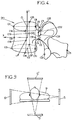
- Each of these images generally comprises several predetermined objects to be examined, for example vertebrae 20 such as the one shown diagrammatically in Figure 4 .
- the microcomputer 17 has, in its memory, a three-dimensional generic model.
- This generic model corresponds, for example, to a specific specimen or to an average form of the object in question, which generic model, in the latter case, is produced in advance by statistical methods and by analyzing a large number of similar objects.
- a technician can for example inform the microcomputer, in particular via a keyboard or mouse, of the nature of each object to be examined which is visible on the images, so that the microcomputer 17 determines the generic model corresponding to this object.
- This step can, if appropriate, be carried out before the examination in order in particular to help the user carry out the adjustments prior to acquisition of the images.
- the generic models used could also be models produced beforehand by medical imaging on the patient P.
- the generic model of each object for example of each vertebra 20 of a human skeleton, comprises:
- axis Z corresponds to the "axial" direction of the vertebral column
- axis X is determined in such a way as to define with the axis Z the antero-posterior plane of the vertebra 20, the axis Y being perpendicular to the axes X, Z.
- the origin O of the reference system X, Y, Z is placed at the centre of the two axial end faces of the body of the vertebra, the origin O moreover being positioned so that the axis Z passes through the upper axial face of the main part of the vertebra at a marker C1 such that the distance from this marker C1 to the front end C7 of the axial face is equal to about 2/3 of the total distance between the front end C7 and rear end C8 of the antero-posterior section of the upper axial face.
- the various control markers C1-C25 are organized in two categories:
- the technician identifies these different control markers for each object to be examined (for example the vertebrae) on each radiographic image, for example by "plotting" these markers on the screen of the microcomputer 17 by selecting them using the mouse and/or keyboard.
- the two images are also calibrated so as to be able to precisely measure the position of each marker of these images in a common reference system.
- a geometric position of each control marker of each object is then determined in a three-dimension reference system, for example the X, Y, Z reference system or a reference system common to all the objects to be examined.
- the position of the stereo-corresponding control markers C1-C6 is calculated directly from the measurement of the position of these points on the two images.
- each non-stereo-corresponding control marker C7-C25 in the three-dimension reference system is estimated from the generic model by moving each stereo-corresponding control marker C1-C6 of the generic model to its measured position, and by moving the non-stereo-corresponding control markers C7-C25 of the generic model, each on a straight line joining:
- ⁇ is a predetermined constant coefficient
- m is a whole number, not zero, representing a number of imaginary springs joining each control marker of the generic model to other control markers
- k i is a predetermined coefficient of stiffness of the imaginary spring of index i
- x i0 is the length of the imaginary spring of index i in the non-deformed generic model
- x i is the length of imaginary spring of index i in the generic model during deformation.
- an actual model representing the vertebra 20 of the patient P is calculated, the actual model being obtained by deformation of the generic model so as to maintain the coincidence of the control points of the generic model during deformation with the previously determined spatial position of the control points and so that this actual model follows a shape which is as close as possible to an isometry of the generic model, this time working on all of the points of the generic model.
- the three-dimensional model of each object to be examined can be obtained in particular by the procedure known as kriging.
- the microcomputer 17 can assemble all of the three-dimensional models of the different objects to be examined, as a function of the position of these different models in an absolute reference system common to all these objects, so as to obtain a three-diemensional model comprising, for example, the whole of the patient's spine.
- this three-dimensional model can be displayed on the screen of the micro-computer 17, or printed out, at the desired angle of vision.
- This overall model can also be moved on screen in accordance with the technician's commands.
- a three dimensional representation of a composite index is obtained.
- the first image being a projection in a plane of the bone mineral density and the second image being a conventional radiography, it is possible to obtain on one hand a tridimensional geometrical reconstruction of each vertebrae, and even of the rachis, and on the other hand, values of the projected bone mineral density for each one of these vertebrae.
- the composite index which is not part of the invention is a combination of physical parameters.
- Knowing geometrical parameters determined from the tridimensional reconstruction and the bone mineral density data allows, for instance, to estimate fracture risks.
- the exemplary embodiment of the method here described can be, of course, used for studying other bone structures than vertebrae.
- twelve human femurs have been studied, nine of them were femal femurs, three of them were male femurs, all the donors were from 65 to 95 years old.
- DXA Dual energy X-ray Absorptiometry
- Le Bras et al. have then determined a linear regression coefficient between the composite index and the fracture load experimentally measured with mechanical tests, comprised between 0.70 and 0.85. In the above-mentioned publication, this value is 0.73 and for the results corresponding to figure 8 , this value is 0.84, when the linear regression coefficient between the projected bone mineral density for a determined femoral neck area and the fracture load is only 0.62 and 0.68 respectively for the above-mentioned publication and figure 7 .
- a practitioner is thus provided with an effective examining tool which can be used for imaging any part, especially an osseous part, of the human or animal body and which is useful in particular for diagnosing osteoporosis or for monitoring certain diseases, also in the periods before and after surgical intervention.
- the device according to the invention can comprise more than two sources 5, 5' and more than two detectors 6, 6', and it would be possible, if appropriate, for the incidences of these different sources of radiation not to be perpendicular with respect to one another.
- the method according to the invention can involve acquisition of more than two images, for example in more than two incidences respectively. If such is the case, it is then possible to perform plotting and reconstruction using the information corresponding to the different images obtained, in a manner analogous to what has been described above.
- the device according to the invention can comprise a single source 5 and one or more detectors 6, the source 5 being able to adopt at least two different relative positions with respect to the patient P, opposite the detector or detectors 6.
- the radiographic device 1 can also be used in two-dimensional radiography, over and above its use in three-dimensional imaging.
- the device and the method according to the invention can be used to perform three-dimensional imaging starting from classical radiology images.
- the functions f i are logarithmic functions.
- the coefficients a i are determined by standardization and by study of the environment of the soft tissues surrounding the bone tissues.
- Im corresponds to the dual-energy case, such as, for example, in the DXA technique (Dual-energy X-ray Absorptiometry).
- the means of reconstruction can be designed to plot contours or points of the surface of said osseous body on an image such as defined above.
- the device according to the invention can include a specific mode for three-dimensional reconstruction of the bone mineral density, or of another composite index, and a mode for three-dimensional reconstruction from classical radiographic images.
- control markers C1-C25 defined in advance on each generic model, it would be possible to determine and spatially position the control markers using contour lines of the object to be observed which are visible on one or other of the two radiographic images.
- the method according to the invention can include a step (h) which consists in performing a radiographic calibration of the three-dimensional environment of said osseous body by defining the three-dimensional reference system in relation to the coordinates, expressed in this reference system, of each X-ray source and of the detection means for each incidence.
- the projections corresponding to the images of the osseous body to be analyzed can be very precisely positioned in this reference system, to permit plotting of the control markers in it.
Landscapes
- Health & Medical Sciences (AREA)
- Life Sciences & Earth Sciences (AREA)
- Medical Informatics (AREA)
- Engineering & Computer Science (AREA)
- Nuclear Medicine, Radiotherapy & Molecular Imaging (AREA)
- Radiology & Medical Imaging (AREA)
- Oral & Maxillofacial Surgery (AREA)
- Biophysics (AREA)
- High Energy & Nuclear Physics (AREA)
- Dentistry (AREA)
- Orthopedic Medicine & Surgery (AREA)
- Optics & Photonics (AREA)
- Pathology (AREA)
- Physics & Mathematics (AREA)
- Biomedical Technology (AREA)
- Heart & Thoracic Surgery (AREA)
- Molecular Biology (AREA)
- Surgery (AREA)
- Animal Behavior & Ethology (AREA)
- General Health & Medical Sciences (AREA)
- Public Health (AREA)
- Veterinary Medicine (AREA)
- Apparatus For Radiation Diagnosis (AREA)
Claims (23)
- Verfahren zur radiographischen Abbildung, aufweisend einen Schritt (d), der aus einem Einführen in Berechnungsmittel (17) erster digitalisierter radiologischer Daten aus Signalen, die von Röntgenstrahldetektionsmitteln (6) geliefert werden und Pixeln eines ersten Bildes eines anatomischen Teils, der einen knöchernen Körper aufweist, entsprechen und in einem ersten Nachweis mit einem Röntgenstrahlbündel mit einem Energiespektrum abgetastet werden, das um zumindest zwei Energien verteilt ist, wobei diese ersten Daten, für jedes Pixel, Koordinaten des Pixels im ersten Bild und einen Absorptiometriewert für jede der Energien aufweisen, wobei die Absorptiometriewerte zum Berechnen der Knochenmineraldichte des knöchernen Körpers, bezogen auf eine Flächeneinheit, bestimmt sind, dadurch gekennzeichnet, dass es einen Schritt (e) aufweist, der aus einem Bestimmen des Wertes eines zusammengesetzten Indexes unter Verwendung einerseits der ersten digitalisierten radiologischen Daten und andererseits eines dreidimensionalen tatsächlichen Modells des knöchernen Körpers besteht, und dass der zusammengesetzte Index eine Kombination aus zumindest zwei Parametern ist, die die Knochenmineraldichte und zumindest einen Parameter aufweisen, ausgewählt aus:- einem speziellen Parameter der Knochengeometrie, ausgewählt aus Winkel, Länge, Oberfläche und Volumen eines knöchernen Teils,und dass ein Bruchrisiko aus dem zusammengesetzten Index evaluiert wird.
- Verfahren nach Anspruch 1, in dem, vor Schritt (d), der aus einem Einführen der ersten radiologischen Daten in die Berechnungsmittel (17) besteht, die folgenden Schritte ausgeführt werden, bestehend aus:(a) Abtasten des einen anatomischen Teils, der den knöchernen Körper aufweist, durch dessen Bestrahlen in zumindest dem ersten Nachweis mit zumindest einem Röntgenstrahlbündel mit einem Energiespektrum, das um zumindest zwei Energien verteilt ist,(b) Erfassen, mit Hilfe von Detektionsmitteln (6), der Strahlungsenergie, die der Röntgenabtastung im ersten Nachweis des einen anatomischen Teils, der den knöchernen Körper aufweist, entspricht und die von dem abgetasteten Teil durchgelassen wird, und Liefern, von den Detektionsmitteln (6), von Signalen, die der durchgelassenen Strahlung entsprechen, und(c) Digitalisieren und Aufzeichnen dieser Signale, die von den Detektionsmitteln (6) geliefert werden und zumindest dem ersten Nachweis entsprechen, zur Erstellung der ersten radiologischen Daten.
- Verfahren nach einem der vorangehenden Ansprüche, in dem Schritt (d) den Vorgang aufweist, der aus einer Rekonstruktion zumindest eines ersten zweidimensionalen Bildes der Knochenmineraldichte jedes abgetasteten Teils des knöchernen Körpers, unter Verwendung der ersten radiologischen Daten besteht.
- Verfahren nach einem der vorangehenden Ansprüche, ebenso aufweisend einen Schritt (d'), der aus einem Einführen in die Berechnungsmittel (17) zweiter digitalisierter radiologischer Daten aus Signalen besteht, die von Röntgenstrahldetektionsmitteln (6) geliefert werden und Pixeln eines zweiten Bildes des anatomischen Teils, der den knöchernen Körper aufweist, entsprechen und mit einem Röntgenstrahlbündel in einem zweiten Nachweis abgetastet werden, der zum ersten Nachweis nicht parallel ist, und in dem die zweiten radiologischen Daten in Schritt (e) zum Bestimmen des Wertes des zusammengesetzten Indexes eingeführt werden.
- Verfahren nach Anspruch 4, in dem, vor Schritt (d'), der aus dem Einführen in die Berechnungsmittel (17) zweiter digitalisierter radiologischer Daten besteht, die folgenden Schritte ausgeführt werden, bestehend aus:(a') Abtasten des einen anatomischen Teils, der den knöchernen Körper aufweist, durch dessen Bestrahlen im zweiten Nachweis mit einem Röntgenstrahlbündel mit einem Energiespektrum, das um zumindest eine Energie verteilt ist;(b') Erfassen, mit Hilfe der Detektionsmittel (6), der Strahlungsenergie, die der Röntgenabtastung im zweiten Nachweis des anatomischen Teils, der den knöchernen Körper aufweist, entspricht und die von dem abgetasteten Teil durchgelassen wird, und Liefern, von den Detektionsmitteln, von Signalen, die der durchgelassenen Strahlung entsprechen, und(c') Digitalisieren und Aufzeichnen der Signale, die von den Detektionsmitteln (6) geliefert werden und dem zweiten Nachweis entsprechen, zur Erstellung der zweiten radiologischen Daten.
- Verfahren nach Anspruch 5, in dem die ersten und zweiten radiologischen Daten im ersten Nachweis bzw. zweiten Nachweis, durch zwei aufeinanderfolgende Abtastungen des anatomischen Teils erhalten werden.
- Verfahren nach Anspruch 5, in dem die ersten und zweiten radiologischen Daten durch gleichzeitiges Abtasten im ersten Nachweis und zweiten Nachweis des anatomischen Teils erhalten werden.
- Verfahren nach einem der Ansprüche 4 bis 7, wobei Schritt (d) den Vorgang aufweist, der aus einer Rekonstruktion eines zweiten zweidimensionalen Bildes, das aus einem radiographischen Standardbild und einem Bild der Knochenmineraldichte des abgetasteten Teils des Körpers, der den knöchernen Körper enthält, ausgewählt ist, unter Verwendung der zweiten radiologischen Daten besteht.
- Verfahren nach einem der vorangehenden Ansprüche, in dem Schritt (e) die folgenden Hilfsschritte aufweist, bestehend aus:(e1) Identifizieren, auf zumindest dem ersten Bild, vorgegebener Marker, die dem knöchernen Körper entsprechen,(e2) Bestimmen, in dem dreidimensionalen Bezugssystem und mit Hilfe erster Rekonstruktionsmittel, der geometrischen Position jedes in Schritt (e1) identifizierten Markers und(e3) Bestimmen, mit Hilfe zweiter Rekonstruktionsmittel, der dreidimensionalen Form des tatsächlichen Modells, das den knöchernen Körper darstellt, durch Verformen eines vorgegebenen generischen Modells, während gleichzeitig Marker dieses generischen Modells während der Verformung in Übereinstimmung gehalten werden, wobei die Marker von den ersten Rekonstruktionsmitteln rekonstruiert werden.
- Verfahren nach Anspruch 9, in dem das generische Modell derart verformt ist, dass das tatsächliche Modell einer Form folgt, die einer Isometrie des generischen Modells so nahe wie möglich ist.
- Verfahren nach Anspruch 9, aufweisend einen Schritt (g), der aus einem Bestimmen, in einem dreidimensionalen Bezugssystem und mit Hilfe dritter Rekonstruktionsmittel, der geometrischen Position dreidimensionaler Konturen besteht, die zu dem knöchernen Körper gehören, indem Marker, die in Schritt (e1) identifiziert wurden, mit dreidimensionalen Konturen des generischen Modells, die auf zumindest das erste Bild projiziert werden, in eine Linie gebracht werden und eine nicht homogene geometrische Verformung des generischen Modells durchgeführt wird, um die Übereinstimmung von Informationen, die von zumindest dem ersten Bild stammen, und Informationen, die das tatsächliche Modell darstellen, zu verbessern.
- Verfahren nach einem der Ansprüche 9 bis 11, in dem:während des Schritts (e1) einige der identifizierten Marker, die als "nicht-stereo-entsprechende Kontrollmarker" bezeichnet werden, nur auf einem einzigen Bild sichtbar und identifiziert sind, undwährend des Schritts (e2) die geometrische Position jedes nicht-stereo-entsprechenden Kontrollmarkers (C7-C25) im dreidimensionalen Bezugssystem aus dem generischen Modell durch Verschieben der nicht-stereo-entsprechenden Kontrollmarker des generischen Modells jeweils auf einer geraden Linie geschätzt wird, die Folgendes verbindet:wodurch die nicht-stereo-entsprechenden Kontrollmarker (C7-C25) an jeweilige Positionen verschoben werden, welche die globale Verformung des generischen Modells des zu beobachtenden Objekts minimieren.- einerseits die Röntgenquelle (5, 11) mit dem Ursprung des Bildes, in dem eine Projektion dieses nicht-stereo-entsprechenden Kontrollmarkers sichtbar und identifizierbar ist, und- andererseits die Projektion dieses Markers auf dieses Bild,
- Verfahren nach Anspruch 12, in dem, während des Vorgangs (e3), der Wert der quadratischen Summe minimiert wird:

- Verfahren nach einem der Ansprüche 9 bis 11, in dem:- während des Schritts (e1) zumindest einige der Marker stereo-entsprechende Kontrollmarker (C1-C6) sind, die auf dem ersten Bild und einem anderen Bild sichtbar und identifiziert sind, und- während des Schritts (e3) die geometrische Position der stereo-entsprechenden Kontrollmarker (C1-C6) direkt aus Messungen einer Position der Projektionen dieser Marker auf das erste Bild und das andere Bild berechnet wird.
- Verfahren nach einem der vorangehenden Ansprüche, aufweisend einen Schritt (h), der aus einer Durchführung einer radiographischen Kalibrierung der dreidimensionalen Umgebung des knöchernen Körpers durch Definieren des dreidimensionalen Bezugssystems besteht, in dem die Koordinaten jeder Röntgenquelle (5) und die Detektionsmittel (6) für jeden Nachweis angegeben sind.
- Verfahren nach einem der vorangehenden Ansprüche, in dem, während des Vorgangs (e), Konturlinien, die Grenzen des knöchernen Körpers und/oder Linien höherer Grauwertdichte innerhalb dieser Grenzen entsprechen, in jedem Bild eingezeichnet werden.
- Vorrichtung zur radiographischen Abbildung, aufweisend:- Berechnungsmittel (17), die zum Berechnen erster digitalisierter radiologischer Daten aus Signalen gestaltet sind, die von Röntgenstrahldetektionsmitteln (6) geliefert werden und Pixeln eines ersten Bildes eines anatomischen Teils, der einen knöchernen Körper aufweist, entsprechen und in einem ersten Nachweis mit einem Röntgenstrahlbündel mit einem Energiespektrum abgetastet werden, das um zumindest zwei Energien verteilt ist, wobei diese ersten Daten, für jedes Pixel, Koordinaten des Pixels im ersten Bild und einen Absorptiometriewert für jede der Energien aufweisen, wobei die Absorptiometriewerte zum Berechnen der Knochenmineraldichte des knöchernen Körpers, bezogen auf eine Flächeneinheit, bestimmt sind, und- Speichermittel zum Speichern zumindest eines dreidimensionalen tatsächlichen Modells des knöchernen Körpers,dadurch gekennzeichnet, dass die Berechnungsmittel (17) auch zum Bestimmen des Wertes eines zusammengesetzten Indexes unter Verwendung einerseits der ersten digitalisierten radiologischen Daten und andererseits zumindest eines dreidimensionalen tatsächlichen Modells des knöchernen Körpers, das in den Speichermitteln gespeichert ist, gestaltet sind,
und dass der zusammengesetzte Index eine Kombination aus zumindest zwei Parametern ist, die die Knochenmineraldichte und zumindest einen Parameter aufweisen, ausgewählt aus:- einem speziellen Parameter der Knochengeometrie, ausgewählt aus Winkel, Länge, Oberfläche und Volumen eines knöchernen Teils,und dass ein Bruchrisiko aus dem zusammengesetzten Index evaluiert wird. - Vorrichtung nach Anspruch 17, zusätzlich aufweisend:- Strahlungserzeugungsmittel (5), die zum Erzeugen, in zumindest einem ersten Nachweis, zumindest eines Röntgenstrahlbündels (10, 11) mit einem Energiespektrum, das um zumindest zwei Energien verteilt ist, und zum Abtasten des einen anatomischen Teils, der den knöchernen Körper aufweist, gestaltet sind,- Detektionsmittel (6), die zum Detektieren der Strahlungsenergie gestaltet sind, die den Röntgenstrahlen entspricht, die im ersten Nachweis den anatomischen Teil, der den knöchernen Körper aufweist, abtasten, und die von jedem der abgetasteten Teile durchgelassen wird, sowie zum Liefern von den Detektionsmitteln (6) von Signalen, die der durchgelassenen Strahlung entsprechen,- Mittel zum Digitalisieren und Aufzeichnen der Signale, die von den Detektionsmitteln (6) geliefert werden und zumindest dem ersten Nachweis entsprechen, zur Erstellung der ersten radiologischen Daten.
- Vorrichtung nach Anspruch 18, in welcher:- die Strahlungserzeugungsmittel (5) auch zum Erzeugen, in einem zweiten Nachweis, der nicht parallel zum ersten Nachweis ist, eines Röntgenstrahlbündels mit einem Energiespektrum, das um zumindest eine Energie verteilt ist, und zum Abtasten zumindest des einen anatomischen Teils, der den knöchernen Körper aufweist, gestaltet sind,- die Detektionsmittel (6) auch zum Detektieren der Strahlungsenergie gestaltet sind, die den Röntgenstrahlen entspricht, die im zweiten Nachweis jeden anatomischen Teil, der den knöchernen Körper aufweist, abtasten, und die von jedem der abgetasteten Teile durchgelassen wird, sowie zum Liefern von Signalen, die der durchgelassenen Strahlung entsprechen,- die Mittel zum Digitalisieren und Aufzeichnen auch zum Digitalisieren und Aufzeichnen der Signale gestaltet sind, die von den Detektionsmitteln geliefert werden und dem zweiten Nachweis entsprechen, um zweite radiologische Daten zu bilden.
- Vorrichtung nach einem der Ansprüche 18 und 19, in welcher:- die Strahlungserzeugungsmittel (5) aus einer einzigen Röntgenstrahlungsquelle bestehen, die abwechselnd zwei Röntgenstrahlbündel erzeugt, von welchem jedes einem anderen Energiespektrum entspricht, wobei diese Strahlungsquelle relativ zum knöchernen Körper in einer Ebene bewegbar ist, die den ersten Nachweis und zweiten Nachweis aufweist, und auch entlang einer Verschiebungsachse senkrecht zu dieser Ebene, und in welcher- die Detektionsmittel (6) aus einem Detektor bestehen, der eine Linie von Detektionszellen senkrecht zur Verschiebungsachse aufweist, wobei die Strahlungsquelle und der Detektor auf einer Quelle-Detektor-Achse ausgerichtet sind, die parallel zu der Ebene liegt, die den ersten Nachweis und zweiten Nachweis aufweist.
- Vorrichtung nach einem der Ansprüche 17 bis 20, in welcher die Berechnungsmittel (17) zum Einzeichnen von Konturen oder Punkten der Oberfläche des knöchernen Körpers in einem Bild der Form:
 - ai reale Koeffizienten sind,- fi Funktionen von R in R sind,- Si (x, y) die Absorptiometriewerte für jedes Pixel (x, y) des Bildes sind, das mit einer Strahlung erhalten wird, deren Energieverteilung einem Spektrum i entspricht.
 - Computerprogramm für eine digitale Verarbeitung radiographischer Bilder, wobei dieses Programm einen Vorgang ausführt, der aus dem Berechnen erster digitalisierter radiologischer Daten aus Signalen, die von Röntgenstrahldetektionsmitteln (6) geliefert werden und Pixeln eines ersten Bildes eines anatomischen Teils, der einen knöchernen Körper aufweist, entsprechen und in einem ersten Nachweis mit einem Röntgenstrahlbündel mit einem Energiespektrum abgetastet werden, das um zumindest zwei Energien verteilt ist, besteht, wobei diese ersten Daten, für jedes Pixel, Koordinaten des Pixels im ersten Bild und einen Absorptiometriewert für jede der Energien aufweisen, wobei die Absorptiometriewerte zum Berechnen der Knochenmineraldichte des knöchernen Körpers, bezogen auf eine Flächeneinheit, bestimmt sind, und
dadurch gekennzeichnet, dass es einen Vorgang ausführt, der aus einem Bestimmen des Wertes eines zusammengesetzten Indexes unter Verwendung einerseits der ersten digitalisierten radiologischen Daten und andererseits eines dreidimensionalen tatsächlichen Modells des knöchernen Körpers besteht, das in Speichermitteln eines Computers gespeichert ist,
und dass der zusammengesetzte Index eine Kombination aus zumindest zwei Parametern ist, die die Knochenmineraldichte und zumindest einen Parameter aufweisen, ausgewählt aus:- einem speziellen Parameter der Knochengeometrie, ausgewählt aus Winkel, Länge, Oberfläche und Volumen eines knöchernen Teils,und dass ein Bruchrisiko aus dem zusammengesetzten Index evaluiert wird. - Computerprogrammprodukt, das Programmcodemittel aufweist, die auf einem Träger gespeichert sind, der von einem Computer lesbar ist, um das Verfahren nach einem der Ansprüche 1 bis 16 auszuführen, wenn das Programmprodukt auf einem Computer läuft.
Applications Claiming Priority (3)
| Application Number | Priority Date | Filing Date | Title |
|---|---|---|---|
| FR0216320 | 2002-12-20 | ||
| FR0216320A FR2849241B1 (fr) | 2002-12-20 | 2002-12-20 | Procede et dispositif d'imagerie radiographique |
| PCT/EP2003/014845 WO2004056270A1 (en) | 2002-12-20 | 2003-11-27 | Method and device for radiographic imaging |
Publications (2)
| Publication Number | Publication Date |
|---|---|
| EP1571998A1 EP1571998A1 (de) | 2005-09-14 |
| EP1571998B1 true EP1571998B1 (de) | 2016-04-27 |
Family
ID=32406271
Family Applications (1)
| Application Number | Title | Priority Date | Filing Date |
|---|---|---|---|
| EP03813604.0A Expired - Lifetime EP1571998B1 (de) | 2002-12-20 | 2003-11-27 | Verfahren undvorrichtung zur radiographischen abbildung |
Country Status (5)
| Country | Link |
|---|---|
| US (1) | US7801350B2 (de) |
| EP (1) | EP1571998B1 (de) |
| AU (1) | AU2003296726A1 (de) |
| FR (1) | FR2849241B1 (de) |
| WO (1) | WO2004056270A1 (de) |
Families Citing this family (24)
| Publication number | Priority date | Publication date | Assignee | Title |
|---|---|---|---|---|
| WO2004081853A1 (en) * | 2003-03-06 | 2004-09-23 | Animetrics, Inc. | Viewpoint-invariant image matching and generation of three-dimensional models from two-dimensional imagery |
| US7643671B2 (en) * | 2003-03-24 | 2010-01-05 | Animetrics Inc. | Facial recognition system and method |
| DE102004033989B4 (de) * | 2004-07-14 | 2015-08-13 | Siemens Aktiengesellschaft | Verfahren zur Messung der dreidimensionalen Dichteverteilung in Knochen |
| US8634629B2 (en) | 2005-11-11 | 2014-01-21 | Hologic, Inc. | Estimating risk of future bone fracture utilizing three-dimensional bone density model |
| US7804992B2 (en) | 2006-10-02 | 2010-09-28 | Hologic, Inc. | Cardiovascular risk assessments using aortic calcification information derived from x-ray measurements taken with a dual energy x-ray densitometer |
| US8660329B2 (en) * | 2007-05-25 | 2014-02-25 | Ecole Nationale Superieure D'arts Et Metiers (Ensam) | Method for reconstruction of a three-dimensional model of a body structure |
| ES2382774B1 (es) | 2010-02-12 | 2013-04-26 | Universitat Pompeu Fabra | Metodo para obtener una reconstruccion tridimensional a partir de una o mas vistas proyectivas, y uso de la misma |
| AU2011266777B2 (en) * | 2010-06-16 | 2015-07-30 | A2 Surgical | Method and system of automatic determination of geometric elements from a 3D medical image of a bone |
| CN102805637B (zh) * | 2011-05-31 | 2014-04-23 | 赵建国 | 一种三维骨密度的计算方法和测量仪 |
| KR101287383B1 (ko) * | 2012-04-27 | 2013-07-19 | 주식회사 인피니트헬스케어 | 의료영상 저장 전송 시스템의 영상 처리, 생성, 저장, 디스플레이 장치 및 방법 |
| ES2445490B1 (es) | 2012-07-31 | 2014-12-10 | Consejo Superior De Investigaciones Cientificas (Csic) | Dispositivo y procedimiento de obtención de imagenes densitométricas de objetos mediante combinación de sistemas radiológicos y cámaras de profundidad |
| JP5931660B2 (ja) * | 2012-09-10 | 2016-06-08 | 住友重機械工業株式会社 | 画像処理方法及び核医学診断装置 |
| GB201402643D0 (en) * | 2014-02-14 | 2014-04-02 | Univ Southampton | A method of mapping images of human disease |
| WO2016138262A1 (en) | 2015-02-26 | 2016-09-01 | Hologic, Inc. | Methods for physiological state determination in body scans |
| FR3035785B1 (fr) * | 2015-05-07 | 2017-06-02 | Arts | Procede d'estimation de la repartition de la densite minerale osseuse dans au moins une partie de squelette d'un individu |
| EP3361958B1 (de) | 2015-10-13 | 2023-01-25 | Mazor Robotics Ltd. | Globales spinales ausrichtung planungs verfahren |
| IT201600109999A1 (it) * | 2016-11-02 | 2018-05-02 | Eurotec Medical Systems S R L | Apparato per densitometria ossea a raggi-x |
| RU2711250C1 (ru) * | 2016-12-15 | 2020-01-15 | Конинклейке Филипс Н.В. | Система кт-визуализации и способ для системы кт-визуализации |
| CA3057566A1 (en) | 2017-03-31 | 2018-10-04 | Hologic, Inc. | Multiple modality body composition analysis |
| FR3074907B1 (fr) * | 2017-12-08 | 2019-12-27 | Tiama | Methode et machine pour controler un procede de formage |
| CN108670302B (zh) * | 2018-06-06 | 2020-11-06 | 西北工业大学 | 一种基于2.5维超声宽景成像的脊柱三维结构再现方法 |
| US12329563B2 (en) | 2019-05-28 | 2025-06-17 | Hologic, Inc. | System and method for continuous calibration of X-ray scans |
| CN119700169B (zh) * | 2025-01-23 | 2025-10-10 | 浙江工业大学 | 一种骨密度检测方法 |
| CN120668522B (zh) * | 2025-08-22 | 2025-10-28 | 广东开放大学(广东理工职业学院) | 一种密度检测模块的测试系统及测试方法 |
Family Cites Families (20)
| Publication number | Priority date | Publication date | Assignee | Title |
|---|---|---|---|---|
| US4029963A (en) | 1976-07-30 | 1977-06-14 | The Board Of Trustees Of Leland Stanford Junior University | X-ray spectral decomposition imaging system |
| US4811373A (en) | 1986-07-14 | 1989-03-07 | Hologic, Inc. | Bone densitometer |
| US5577089A (en) | 1991-02-13 | 1996-11-19 | Lunar Corporation | Device and method for analysis of bone morphology |
| FR2705785B1 (fr) | 1993-05-28 | 1995-08-25 | Schlumberger Ind Sa | Procédé pour déterminer la fonction d'atténuation d'un objet par rapport à la transmission d'une épaisseur de référence d'un matériau de référence et dispositif pour la mise en Óoeuvre du procédé. |
| FR2705786B1 (fr) | 1993-05-28 | 1995-08-25 | Schlumberger Ind Sa | Procédé et dispositif pour la reconnaissance de matériaux déterminés dans la composition d'un objet. |
| US5432834A (en) | 1993-11-22 | 1995-07-11 | Hologic, Inc. | Whole-body dual-energy bone densitometry using a narrow angle fan beam to cover the entire body in successive scans |
| US5838765A (en) | 1993-11-22 | 1998-11-17 | Hologic, Inc. | Whole-body x-ray bone densitometry using a narrow-angle fan beam, including variable fan beam displacement between scan passes |
| US5850836A (en) | 1995-09-22 | 1998-12-22 | Hologic, Inc. | Morphometric x-ray absorptiometry (MXA) |
| US5483960A (en) | 1994-01-03 | 1996-01-16 | Hologic, Inc. | Morphometric X-ray absorptiometry (MXA) |
| US6438201B1 (en) * | 1994-11-23 | 2002-08-20 | Lunar Corporation | Scanning densitometry system with adjustable X-ray tube current |
| FR2798260B1 (fr) | 1999-09-10 | 2001-12-07 | Abc Metal Sarl | Procede et dispositif de traitement de vegetaux apres recolte |
| US6173038B1 (en) | 1999-12-01 | 2001-01-09 | Cyberlogic, Inc. | Plain x-ray bone densitometry apparatus and method |
| WO2001057882A1 (en) | 2000-02-01 | 2001-08-09 | The Johns Hopkins University | Focused x-ray scatter reduction grid |
| FR2810769B1 (fr) * | 2000-06-23 | 2002-10-11 | Biospace Instr | Procede et dispositif d'imagerie radiographique pour la reconstitution tridimensionnelle a faible dose d'irradiation |
| US7660453B2 (en) * | 2000-10-11 | 2010-02-09 | Imaging Therapeutics, Inc. | Methods and devices for analysis of x-ray images |
| EP1379172A2 (de) * | 2000-10-24 | 2004-01-14 | The Johns Hopkins University | Verfahren und vorrichtung zur abtastung mittels röntgenabsorptionsspektroskopie bei zwei energien mit mehrfachprojektion |
| WO2002038045A2 (en) | 2000-11-08 | 2002-05-16 | The Johns Hopkins University | Techniques for deriving tissue structure from multiple projection dual-energy x-ray absorptiometry |
| US6501819B2 (en) * | 2000-12-18 | 2002-12-31 | Ge Medical Systems Global Technology Company, Llc | Medical diagnostic method and apparatus to control dual energy exposure techniques based on image information |
| BR0116855B1 (pt) * | 2001-02-07 | 2012-06-12 | processo para estabelecer uma representaÇço tridimensional virtual de um osso ou fragmento de osso a partir de imagens de raios-x. | |
| JP2005516376A (ja) | 2002-01-31 | 2005-06-02 | ザ ジョンズ ホプキンズ ユニバーシティ | 選択可能なx線周波数をより効率よく生成するx線源および方法 |
-
2002
- 2002-12-20 FR FR0216320A patent/FR2849241B1/fr not_active Expired - Lifetime
-
2003
- 2003-11-27 WO PCT/EP2003/014845 patent/WO2004056270A1/en not_active Ceased
- 2003-11-27 AU AU2003296726A patent/AU2003296726A1/en not_active Abandoned
- 2003-11-27 US US10/540,107 patent/US7801350B2/en active Active
- 2003-11-27 EP EP03813604.0A patent/EP1571998B1/de not_active Expired - Lifetime
Also Published As
| Publication number | Publication date |
|---|---|
| EP1571998A1 (de) | 2005-09-14 |
| AU2003296726A1 (en) | 2004-07-14 |
| FR2849241B1 (fr) | 2005-06-24 |
| US20060204069A1 (en) | 2006-09-14 |
| US7801350B2 (en) | 2010-09-21 |
| FR2849241A1 (fr) | 2004-06-25 |
| WO2004056270A1 (en) | 2004-07-08 |
Similar Documents
| Publication | Publication Date | Title |
|---|---|---|
| EP1571998B1 (de) | Verfahren undvorrichtung zur radiographischen abbildung | |
| EP2245569B1 (de) | Medizinisches abbildungsverfahren und system zur bereitstellung eines finite-elemente-modells | |
| EP3461412B1 (de) | System und verfahren zur dxa-tomo-basierten finite-element-analyse von knochen | |
| US9142020B2 (en) | Osteo-articular structure | |
| US20210056688A1 (en) | Using deep learning to reduce metal artifacts | |
| US7639866B2 (en) | Method of radiographic imaging for three-dimensional reconstruction, and a computer program and apparatus for implementing the method | |
| EP3486873B1 (de) | Automatische implantatdetektion aufgrund von bildartefakten | |
| TWI507175B (zh) | 骨密度測量裝置 | |
| US8498374B2 (en) | Dental and orthopedic densitometry modeling system and method | |
| EP4056120B1 (de) | Schätzvorrichtung, schätzverfahren und schätzprogramm | |
| JP2009101157A (ja) | 画像誘導による定量的二重エネルギ・データの取得 | |
| US20030048873A1 (en) | Method for improving a radiological examination and device therefor | |
| US7174000B2 (en) | Method for measurement of the three-dimensional density distribution in bones | |
| Jan et al. | Low-dose computed tomography: a solution for in vivo medical imaging and accurate patient-specific 3D bone modeling? | |
| Crabtree et al. | Vertebral morphometry: repeat scan precision using the Lunar Expert-XL and the Hologic 4500A. A study for the “WISDOM” RCT of hormone replacement therapy | |
| JPH10509074A (ja) | フィルムカセット付き骨濃度計 | |
| CN120051252A (zh) | 在由cbct扫描器系统产生的图像上的脊柱硬件植入物上叠加渲染的方法 | |
| KR20160126195A (ko) | 컴퓨터를 이용한 x-선 영상처리 골 모델링 작성방법, 시스템 및 컴퓨터 프로그램 | |
| Wesarg et al. | CAD of osteoporosis in vertebrae using dual-energy CT | |
| García-Ruesgas et al. | Projective geometric model for automatic determination of X-ray-emitting source of a standard radiographic system | |
| EP3756546A1 (de) | Knochentrabekelindex für röntgen-dunkelfeld-radiografie | |
| Oliviero | Non-invasive prediction of bone mechanical properties of the mouse tibia in longitudinal preclinical studies |
Legal Events
| Date | Code | Title | Description |
|---|---|---|---|
| PUAI | Public reference made under article 153(3) epc to a published international application that has entered the european phase |
Free format text: ORIGINAL CODE: 0009012 |
|
| 17P | Request for examination filed |
Effective date: 20050617 |
|
| AK | Designated contracting states |
Kind code of ref document: A1 Designated state(s): AT BE BG CH CY CZ DE DK EE ES FI FR GB GR HU IE IT LI LU MC NL PT RO SE SI SK TR |
|
| AX | Request for extension of the european patent |
Extension state: AL LT LV MK |
|
| DAX | Request for extension of the european patent (deleted) | ||
| RBV | Designated contracting states (corrected) |
Designated state(s): DE FR GB SE |
|
| RAP1 | Party data changed (applicant data changed or rights of an application transferred) |
Owner name: BIOSPACE MED |
|
| 17Q | First examination report despatched |
Effective date: 20070301 |
|
| RAP1 | Party data changed (applicant data changed or rights of an application transferred) |
Owner name: EOS IMAGING |
|
| APBK | Appeal reference recorded |
Free format text: ORIGINAL CODE: EPIDOSNREFNE |
|
| APBN | Date of receipt of notice of appeal recorded |
Free format text: ORIGINAL CODE: EPIDOSNNOA2E |
|
| APBR | Date of receipt of statement of grounds of appeal recorded |
Free format text: ORIGINAL CODE: EPIDOSNNOA3E |
|
| APAF | Appeal reference modified |
Free format text: ORIGINAL CODE: EPIDOSCREFNE |
|
| APBT | Appeal procedure closed |
Free format text: ORIGINAL CODE: EPIDOSNNOA9E |
|
| GRAP | Despatch of communication of intention to grant a patent |
Free format text: ORIGINAL CODE: EPIDOSNIGR1 |
|
| INTG | Intention to grant announced |
Effective date: 20151117 |
|
| RIN1 | Information on inventor provided before grant (corrected) |
Inventor name: KOLTA, SAMI Inventor name: LE BRAS, ANTHONY Inventor name: TEYSSEYRE, SEBASTIEN Inventor name: SKALLI, WAFA Inventor name: ROUX, CHRISTIAN Inventor name: FECHTENBAUM, JACQUES Inventor name: MITTON, DAVID Inventor name: DE GUISE, JACQUES, A. |
|
| GRAS | Grant fee paid |
Free format text: ORIGINAL CODE: EPIDOSNIGR3 |
|
| GRAA | (expected) grant |
Free format text: ORIGINAL CODE: 0009210 |
|
| AK | Designated contracting states |
Kind code of ref document: B1 Designated state(s): DE FR GB SE |
|
| REG | Reference to a national code |
Ref country code: GB Ref legal event code: FG4D |
|
| REG | Reference to a national code |
Ref country code: DE Ref legal event code: R096 Ref document number: 60348898 Country of ref document: DE |
|
| REG | Reference to a national code |
Ref country code: FR Ref legal event code: PLFP Year of fee payment: 14 |
|
| PG25 | Lapsed in a contracting state [announced via postgrant information from national office to epo] |
Ref country code: SE Free format text: LAPSE BECAUSE OF FAILURE TO SUBMIT A TRANSLATION OF THE DESCRIPTION OR TO PAY THE FEE WITHIN THE PRESCRIBED TIME-LIMIT Effective date: 20160427 |
|
| REG | Reference to a national code |
Ref country code: DE Ref legal event code: R097 Ref document number: 60348898 Country of ref document: DE |
|
| PLBE | No opposition filed within time limit |
Free format text: ORIGINAL CODE: 0009261 |
|
| STAA | Information on the status of an ep patent application or granted ep patent |
Free format text: STATUS: NO OPPOSITION FILED WITHIN TIME LIMIT |
|
| 26N | No opposition filed |
Effective date: 20170130 |
|
| REG | Reference to a national code |
Ref country code: FR Ref legal event code: PLFP Year of fee payment: 15 |
|
| PGFP | Annual fee paid to national office [announced via postgrant information from national office to epo] |
Ref country code: FR Payment date: 20221021 Year of fee payment: 20 |
|
| PGFP | Annual fee paid to national office [announced via postgrant information from national office to epo] |
Ref country code: GB Payment date: 20221121 Year of fee payment: 20 Ref country code: DE Payment date: 20221114 Year of fee payment: 20 |
|
| P01 | Opt-out of the competence of the unified patent court (upc) registered |
Effective date: 20230525 |
|
| REG | Reference to a national code |
Ref country code: DE Ref legal event code: R071 Ref document number: 60348898 Country of ref document: DE |
|
| REG | Reference to a national code |
Ref country code: GB Ref legal event code: PE20 Expiry date: 20231126 |
|
| PG25 | Lapsed in a contracting state [announced via postgrant information from national office to epo] |
Ref country code: GB Free format text: LAPSE BECAUSE OF EXPIRATION OF PROTECTION Effective date: 20231126 |
|
| PG25 | Lapsed in a contracting state [announced via postgrant information from national office to epo] |
Ref country code: GB Free format text: LAPSE BECAUSE OF EXPIRATION OF PROTECTION Effective date: 20231126 |