EP1571750A2 - Rotary machine - Google Patents
Rotary machine Download PDFInfo
- Publication number
- EP1571750A2 EP1571750A2 EP05004458A EP05004458A EP1571750A2 EP 1571750 A2 EP1571750 A2 EP 1571750A2 EP 05004458 A EP05004458 A EP 05004458A EP 05004458 A EP05004458 A EP 05004458A EP 1571750 A2 EP1571750 A2 EP 1571750A2
- Authority
- EP
- European Patent Office
- Prior art keywords
- conductors
- slots
- stator
- winding
- slot
- Prior art date
- Legal status (The legal status is an assumption and is not a legal conclusion. Google has not performed a legal analysis and makes no representation as to the accuracy of the status listed.)
- Withdrawn
Links
Images


Classifications
-
- H—ELECTRICITY
- H02—GENERATION; CONVERSION OR DISTRIBUTION OF ELECTRIC POWER
- H02K—DYNAMO-ELECTRIC MACHINES
- H02K3/00—Details of windings
- H02K3/04—Windings characterised by the conductor shape, form or construction, e.g. with bar conductors
- H02K3/12—Windings characterised by the conductor shape, form or construction, e.g. with bar conductors arranged in slots
-
- H—ELECTRICITY
- H02—GENERATION; CONVERSION OR DISTRIBUTION OF ELECTRIC POWER
- H02K—DYNAMO-ELECTRIC MACHINES
- H02K3/00—Details of windings
- H02K3/46—Fastening of windings on the stator or rotor structure
- H02K3/50—Fastening of winding heads, equalising connectors, or connections thereto
-
- H—ELECTRICITY
- H02—GENERATION; CONVERSION OR DISTRIBUTION OF ELECTRIC POWER
- H02K—DYNAMO-ELECTRIC MACHINES
- H02K2203/00—Specific aspects not provided for in the other groups of this subclass relating to the windings
- H02K2203/09—Machines characterised by wiring elements other than wires, e.g. bus rings, for connecting the winding terminations
Definitions
- the present invention relates to a stator of a rotary machine and more particularly of a rotary machine of an AC generator for vehicle for generating power by being driven by an internal combustion engine and supplying power to a mobile electric load and a mobile power source.
- Patent Document 1 Japanese Patent No.3201397
- Patent Document 2 Japanese Patent No. 3303854
- Patent Document 1 Japanese Patent No.3201397
- Patent Document 2 Japanese Patent No. 3303854
- Patent Document 1 between two conductor terminals neighboring in the peripheral direction, a retainer is arranged in contact with the conductor terminals on both sides to retain the conductor terminals. With the conductor terminals being retained, the front ends thereof are joined to each other.
- the manufacturing method of Patent Document 1 after junction, moves and releases the retainer.
- Patent Document 2 the junction method for notching a conductor terminal, making the sectional area of the notched part smaller than those of other parts, thereby reducing the quantity of input heat is used.
- Patent Document 3 Japanese Application Patent Laid-open Publication No. Hei 11-155270
- Patent Document 3 Japanese Application Patent Laid-open Publication No. Hei 11-155270
- electric conductors stored in a plurality of first slots separating in correspondence with the NS magnetic pole pitch of the stator are connected electrically in series to form a first winding
- electric conductors stored in a plurality of second slots neighboring the first slots are connected electrically in series to form a second winding.
- the first winding and second winding are connected electrically in series to form the winding of the stator.
- the inner diameter and outer diameter of each conductor terminal and the neighboring conductor terminals are retained by the retainers and are fused by TIG.
- the heat withdrawal quantity for input heat is changed and the fusion status is changed.
- the retainers serve as a plus electrode.
- the fusion area is required to be larger than the sectional area of the conductors, so that the fused part is larger than the sectional area of the conductors. Therefore, the retainers for the inner diameter and outer diameter, after connection, may not be taken out from products.
- the conductor terminals are notched.
- a step of notching the terminals after cutting the conductors in a fixed size or forming them in a U shape is necessary and line manufacture cannot be realized.
- to fuse the terminals by TIG they must be separated on the four surfaces (all the surfaces) and the separation step is complicated.
- the neighborhood of junction may be made fragile due to the hot shortness, so that as a conductor material, expensive non-oxygen copper must be adopted.
- the first winding and second winding electrically phase-shifted are connected electrically in series, thus the electromotive ripple force is reduced and the magnetic noise is reduced.
- the electric conductors in the same slot are connected electrically in series to form the first winding and second winding.
- the electromotive force distribution of the stator winding includes a large amount of high frequency component.
- the high frequency component causes an increase in magnetic noise.
- the electromotive force distribution of the stator winding can be made smooth, and the high frequency component included in the electromotive force distribution can be reduced, and the magnetic noise can be reduced.
- arrangement of the conductors in the neighboring slots complicatedly increases the conductor kinds and in correspondence to it, a problem arises that the manufacturing steps are complicated.
- An object of the present invention is to examine both sides of the product structure and manufacturing steps and to provide a rotary machine having a stator which can be manufactured easily. Further, another object of the present invention is to provide a rotary machine having a phase winding circuit which can reduce the magnetic noise and can be easily manufactured.
- the present invention is a rotary machine having a stator composed of a stator iron core having a plurality of slots formed in the direction of the rotation axis and stator windings inserted into the plurality of slots, wherein the stator windings are composed of a plurality of conductors respectively inserted into the plurality of slots in the direction of the rotation axis and the stator has a connection ring having the slots into which the plurality of conductors are inserted in the direction of the rotation axis.
- the present invention is a rotary machine including a stator having a stator iron core having a plurality of slots formed in the direction of the rotation axis and stator windings composed of a plurality of conductors respectively inserted into the plurality of slots and a rotor having a plurality of magnetic poles arranged so that the polarity alternately differs in the rotational direction and an air gap formed between the rotor and the stator, wherein the stator windings are composed of several multi-phase windings, and one multi-phase winding is composed of two or more phase windings, and the phase winding in correspondence to one phase is composed of the plurality of conductors electrically connected across the slots of the stator iron core so as to correspond to the plurality of magnetic poles, and the winding start of one multi-phase winding and the winding end of another multi-phase winding are connected by conductors twisted in the opposite direction of the plurality of conductors electrically connected across the slots of the stator iron core so as to correspond to correspond
- the present invention is a rotary machine including a stator having a stator iron core having a plurality of slots formed in the direction of the rotation axis and stator windings composed of a plurality of conductors respectively inserted into the plurality of slots and a rotor having a plurality of magnetic poles arranged so that the polarity alternately differs in the rotational direction and an air gap formed between the rotor and the stator, wherein the stator windings are composed of several multi-phase windings, and one multi-phase winding is composed of two or more phase windings, and the phase winding in correspondence to one phase is composed of the plurality of conductors electrically connected across the slots of the stator iron core so as to correspond to the plurality of magnetic poles, and the multi-phase windings are electrically connected by conductors having a different spanning width, and some conductors of neighboring slots have the same phase.
- the present invention is a rotary machine including a stator having a stator iron core having a plurality of slots formed in the direction of the rotation axis and stator windings composed of a plurality of conductors respectively inserted into the plurality of slots and a rotor having a plurality of magnetic poles arranged so that the polarity alternately differs in the rotational direction and an air gap formed between the rotor and the stator, wherein the stator windings are composed of several multi-phase windings, and one multi-phase winding is composed of two or more phase windings, and the phase winding in correspondence to one phase is composed of the plurality of conductors electrically connected across the slots of the stator iron core so as to correspond to the plurality of magnetic poles, and in the stator windings, the number of slots per pole and per phase which is decided from the number of phases, the number of slots, and the number of magnetic poles is 2.5, and the number of magnetic poles composed of 5 conductors per magnetic pole is 12, and
- the present invention is a rotary machine that for the two magnetic poles of the rotor, that is, for a pair of magnetic poles of the N pole and S pole which are different from each other, 15 slots mentioned above are arranged, and the stator windings are electrically connected by the conductors at an angle that the spanning width is equivalent to 7 slots and at an angle that the twisting angle of both terminals is equivalent to 4 slots.
- the present invention is a rotary machine that the 3 inner conductors and 3 outer conductors are respectively divided into 2 conductors and 1 conductor, and the 2 inner conductors and 2 outer conductors are respectively divided into one conductor, and each winding is formed to a wave winding.
- the present invention is a rotary machine that the conductors divided into two conductors are arranged in the neighboring slots and are electrically connected by the conductors having a different spanning width, thus a circuit is formed.
- the present invention is a rotary machine that the winding start and winding end of each wave winding are electrically connected by bridge lines arranged on the innermost layer and outermost layer, thus a circuit is formed.
- the present invention is a rotary machine that the winding end of the inside circuit and the winding start of the outside circuit are electrically connected by the reversely twisted conductor, thus a circuit is formed.
- the present invention is a rotary machine further comprising a connection ring for attaching and fixing the terminal portion when electrically connecting and forming a circuit.
- the present invention is a rotary machine including a stator having a stator iron core having a plurality of slots formed in the direction of the rotation axis and stator windings composed of a plurality of conductors respectively inserted into the plurality of slots and a rotor having a plurality of magnetic poles arranged so that the polarity alternately differs in the rotational direction and an air gap formed between the rotor and the stator, wherein the stator windings are composed of several multi-phase windings, and one multi-phase winding is composed of two or more phase windings, and the phase winding in correspondence to one phase is composed of the plurality of conductors electrically connected across the slots of the stator iron core so as to correspond to the plurality of magnetic poles, and in the stator windings, the number of slots per pole and per phase which is decided from the number of phases, the number of slots, and the number of magnetic poles is 2.5, and the number of magnetic poles composed of 5 conductors per magnetic pole is 12, and
- the present invention is a rotary machine that the 3 inner conductors and 3 outer conductors are respectively divided into 2 conductors and 1 conductor, and the 2 inner conductors and 2 outer conductors are respectively divided into one conductor, and each winding is formed to a wave winding.
- the present invention is a rotary machine that the conductors divided into two conductors are arranged in the neighboring slots and are electrically connected by the conductors having a different spanning width, thus a circuit is formed.
- the present invention is a rotary machine that the winding start and winding end of each conductor which is formed to a wave winding are electrically connected by bridge lines arranged on the innermost layer and outermost layer, thus a circuit is formed.
- the present invention is a rotary machine including a stator having a stator iron core having a plurality of slots formed in the direction of the rotation axis and stator windings composed of a plurality of conductors respectively inserted into the plurality of slots and a rotor having a plurality of magnetic poles arranged so that the polarity alternately differs in the rotational direction and an air gap formed between the rotor and the stator, wherein the stator windings are composed of several multi-phase windings, and one multi-phase winding is composed of two or more phase windings, and the phase winding in correspondence to one phase is composed of the plurality of conductors electrically connected across the slots of the stator iron core so as to correspond to the plurality of magnetic poles, and in the stator windings, the number of slots per pole and per phase which is decided from the number of phases, the number of slots, and the number of magnetic poles is 2.5, and the number of magnetic poles composed of 5 conductors per magnetic pole is 12, and
- the stator of the rotary machine of the present invention is characteristically multipoint-connected by the connection ring.
- the connection ring When the conductor terminals are connected by the connection ring, there is no need to work on the conductor terminals such as notching. Further, when the connection ring is attached to the conductor terminals, the terminal position is fixed, so that the retainer for positioning the conductors is not required.
- an armature winding is formed.
- the sectional area of the joined part can be set to the sectional area of one conductor or more.
- the connection method can be executed by fusing, so that the terminals are separated on two surfaces and can be connected. Further, the joined part is not fused, so that there is no need to use expensive non-oxygen copper and ordinary tough pitch copper can be used.
- stator of the rotary machine of the present invention the high frequency component included in the electromotive force distribution can be reduced and the magnetic noise can be reduced. Further, the aforementioned stator of the rotary machine is characterized in consideration of the producibility and process simplification.
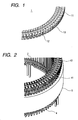
- Fig. 1 is an enlarged view of the connection ring in Embodiment 1;
- Fig. 2 is an enlarged view of the connection ring attached status in Embodiment 1;
- Fig. 3 is an enlarged view of the status of the connection ring after division in Embodiment 1;
- Fig. 4 is a status diagram of the connection ring after division in Embodiment 1;
- Fig. 5 is an enlarged view of the status that reversely twisted conductors are connected in Embodiment 2;
- Fig. 6 is an enlarged view of the status that conductors having a different spanning width are connected in Embodiment 3;
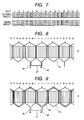
- Fig. 7 is a layout diagram of the slots per two magnetic poles of the rotor in Embodiment 4;
- FIG. 8 is a 2T circuit diagram of the stator winding of the rotary machine in Embodiment 4;
- Fig. 9 is a 3T circuit diagram of the stator winding of the rotary machine in Embodiment 4;
- Fig. 10 is an appearance view of the outside circuit of the stator which is wave-wound by 2T in Embodiment 4:
- Fig. 11 is an appearance view of the outside circuit of the stator which is wave-wound by 3T in Embodiment 4;
- Fig. 12 is an appearance view of the stator of the rotary machine in which the part in correspondence to one phase is attached in Embodiment 4;
- Fig. 13 is an appearance view of the stator winding of the rotary machine in Embodiment 4;
- Fig. 10 is an appearance view of the outside circuit of the stator which is wave-wound by 2T in Embodiment 4;
- Fig. 11 is an appearance view of the outside circuit of the stator which is wave-wound
- Fig. 14 is an attaching appearance view of the connection ring of the stator of the rotary machine in Embodiment 4;
- Fig. 15 is a 2T circuit diagram of the stator winding of the rotary machine in Embodiment 5;
- Fig. 16 is a 3T circuit diagram of the stator winding of the rotary machine in Embodiment 5;
- Fig. 17 is an appearance view of the outside circuit of the stator which is wave-wound by 2T in Embodiment 5;
- Fig. 18 is an appearance view of the outside circuit of the stator which is wave-wound by 3T in Embodiment 5;
- Fig. 19 is an appearance view of the stator of the rotary machine in which the part in correspondence to one phase is attached in Embodiment 5;
- Fig. 20 is an appearance view of the stator of the rotary machine in Embodiment 5; and
- Fig. 21 is a layout diagram of the slots of the unbalanced winding in Embodiment
- the stator of the rotary machine of the present invention for facilitating manufacture can be realized by use of a constitution of attaching a connection ring to a plurality of conductor terminals and fixing the connection position.
- Each conductor terminal of a stator winding can be structured so as to simultaneously execute two-surface separation symmetrical right and left for the wide surface at the time of cutting in fixed size and forming the front end in a nail shape symmetrical right and left and symmetrical up and down.
- the conductor cut in a fixed size is formed in a U shape in the forcibly retained state and a plurality of conductors necessary for a stator winding per machine can be manufactured continuously from cutting in a fixed size to forming in a U shape. Since the front end is formed in a nail shape, into a stator iron core with a plurality of slots formed, a plurality of conductors can be inserted at a time in the direction of the rotation axis. Further, the connection ring can be easily attached at the conductor terminal position. By use of a constitution that the connection ring is attached and the connection position is fixed, it can be formed to a constitution that the neighboring conductor terminals can preserve a uniform insulating space.
- the stator of the rotary machine of the present invention for reducing the magnetic noise can be realized by use a constitution that the number of magnetic poles is 12, and the number of slots is 90, and the number of phases of the stator winding is 3, and the number of slots per pole and per phase which is decided from the number of poles is 2.5, and one magnetic pole is composed of 5 conductors.
- the conductors inserted into the stator winding in the axial direction there is a problem imposed in the periodicity, so that the number of winding conductors stored in one slot must be an even number.
- stator of the rotary machine 4 conductors are arranged in each slot, and in a plurality of neighboring slots, 5 conductors are arranged for each magnetic pole, and the conductors per magnetic pole are formed by a double circuit of an inside circuit and an outside circuit, so that the manufacturing process can be divided and the equipment can be simplified. Further, in the phase winding, the inside circuit and outside circuit are combined, and 5 conductors combining 3 conductors of the inside circuit and 2 conductors of the outside circuit and 5 conductors combining 2 conductors of the inside circuit and 3 conductors of the outside circuit are combined, thus an almost balanced winding can be obtained and the magnetic noise can be reduced.
- the inside circuit and outside circuit are composed of a wave winding circuit and the number of windings per phase is 30.
- the wave winding circuit makes a round of six windings and the slot position of the winding start and the slot position of the winding end of the sixth winding are the same slot.
- the conductor of the sixth winding at the winding end of the first round is a conductor having a different spanning width and when it is arranged at the neighboring slot position, for the winding start of the second round starting winding from the neighboring slot and the winding end of the second round, the connection can be abolished.
- the phase winding when the winding is started from the inside, the winding end of the inside circuit is connected to the winding start of the outside circuit.
- the conductor at the winding end of the inside circuit is formed in a reversely twisted shape of the twisting direction of the other conductors, it can be set at the slot position of winding start of the outside circuit free of interference with the other conductors and the connection of the winding end of the inside circuit and the winding start of the outside circuit can be abolished.
- the terminals are connected, thus the circuit is formed.
- the connection ring is attached to the terminals, thus the terminal position can be surely fixed and a stable connection can be obtained.
- Fig. 1 shows an enlarged view of the connection ring used in this embodiment
- Fig. 2 shows an enlarged view of the connection ring attached status
- Fig. 3 shows an enlarged view of the status of the connection ring after division
- Fig. 4 shows a status diagram of the connection ring after division.
- Figs. 1 to 4 show an example that the number of slots is 90 and 4 conductors are arranged in each slot.
- a connection ring 1 is composed of a conductor portion 11 and an insulating portion 12.
- the connection ring 1 has a plurality of slots 13 corresponding to the number of connection points of a terminal portion 42 of a plurality of conductors 41, and between the plurality of slots 13 and the plurality of neighboring slots 13, the insulating portion 12 is arranged, thus uniform insulation is obtained.
- Four conductors are arranged in each slot, so that with respect to the terminal portion 42, from the outer peripheral side, the first and second terminals and the third and fourth terminals are connected in a twin state, thus 90 slots 13 of the connection ring 1 are arranged on the outer peripheral side and 90 slots 13 are arranged on the inner peripheral side.
- the upper part of the conductor portion 11 is connected and continuity reservation at the time of attaching to the conductor terminals and connection by fusing is taken into account.
- a conductor group 4 is inserted and arranged in the direction of the rotation axis.
- the connection ring 1 is attached to the terminal portion 42 of the plurality of conductors 41 of the stator 2.
- the connection ring after attaching, is tightened temporarily by calking by pushing the terminal portion 42 into the slots 13 of the connection ring 1 and is thermally tightened by fusing in this posture kept.
- the upper part of the conductor portion 11 is cut, and the connection ring 1 is separated, thus the stator winding is formed.
- Fig. 5 is an enlarged view of the status that reversely twisted conductors are connected and shows an example that the number of slots is 90 and 4 conductors are arranged in each slot.
- Four conductors are arranged in each slot, so that the phase winding is formed by an outside circuit 6 composed of a plurality of first and second conductors 41 from the outer peripheral side and an inside circuit 7 composed of a plurality of third and fourth conductors 41 and is formed by connecting a conductor 46 at the winding end of the outside circuit and a conductor 48 at the winding start of the inside circuit.
- the connection of the conductor 46 at the winding end of the outside circuit and the conductor 48 at the winding start of the inside circuit can be abolished by use of reversely twisted conductors 43.
- Fig. 6 is an enlarged view of the status that the conductors having a different spanning width are connected and shows an example of a winding circuit in which the number of magnetic poles is 12, and the number of slots is 90, and the number of phases of the stator winding is 3, and the number of slots per pole and per phase which is decided from the number of poles is 2.5, and one magnetic pole is composed of 5 conductors, and 4 conductors are arranged in each slot.
- the winding circuit four conductors are arranged in each slot in a row in the radial direction, and the conductors are divided into the first and second conductors and the third and fourth conductors from the outer peripheral side, and the outside circuit 6 composed of the first and second conductors of the plurality of slots and the inside circuit 7 composed of the third and fourth conductors thereof are combined.
- the plurality of conductors 41 are in a shape twisted so that the spanning width is equivalent to 7 slots and both terminal sides are respectively equivalent to 4 slots or the spanning width is equivalent to 8 slots and both terminal sides are respectively equivalent to 3.5 slots, and the terminals at both ends are respectively arranged in the first slot and the second slot from the outer peripheral side.
- the first terminal of the terminal portion 42 of the plurality of conductors 41 and the second terminal of the terminal portion 42 of the other plurality of conductors 41 are connected.
- connection is sequentially repeated to form a wave winding and the wave winding makes a round of 6 windings at the winding start position.
- the neighboring slots equal in the phase, in the location where the plurality of conductors 41 at the sixth winding are arranged, by arranging conductors 44 having a different spanning width without connecting the winding end at the first round to the winding start at the second round arranged in the neighboring slot, a wave winding can be formed.
- Fig. 7 shows a layout diagram of the slots per two magnetic poles of the rotor
- Fig. 8 shows a 2T circuit diagram of the stator winding of the rotary machine
- Fig. 9 shows a 3T circuit diagram of the stator winding of the rotary machine.
- Fig. 7 in the winding circuit in which the number of magnetic poles is 12, and the number of slots is 90, and the number of phases of the stator winding is 3, and the number of slots per pole and per phase which is decided from the number of poles is 2.5, and one magnetic pole is composed of 5 conductors, per two magnetic poles (a pair of N pole and S pole which are different from each other) of the rotor, 15 slots are arranged. Further, four conductors are arranged in each slot and in a plurality of neighboring slots, five conductors are arranged for each magnetic pole.
- the winding circuit In the winding circuit, four conductors are arranged in each slot in a row in the radial direction, and the conductors are divided into the first and second conductors and the third and fourth conductors from the outer peripheral side, and the inside circuit 7 composed of the third and fourth conductors of the plurality of slots and the outside circuit 6 composed of the first and second conductors thereof are combined, and 5 conductors combining 3 conductors of the inside circuit 7 and 2 conductors of the outside circuit 6 and 5 conductors combining 2 conductors of the inside circuit 7 and 3 conductors of the outside circuit 6 are combined, thus an almost balanced winding can be obtained.
- the conductor group 4 arranged in the stator 2 is composed of the plurality of conductors 41, the winding start conductor 45, the winding end conductor 46, and the bridge lines 47.
- the plurality of conductors 41 are in a shape that the spanning width is equivalent to 7 slots, and the twisting angle is 28°, and the terminals at both ends are respectively arranged in the first slot and second slot from the outer peripheral side.
- the winding start conductor 45 arranged in the second slot from the outer peripheral side of the slot No. 1 of the stator 2 is connected to the plurality of conductors 41 arranged in the first slot of the slot No. 83.
- the other terminal of the plurality of conductors 41 arranged in the first slot of the slot No. 83 is arranged in the second slot of the slot No. 76 across 7 slots.
- the other plurality of conductors 41 are arranged in the first slot of the slot No. 68 and the second slot of the slot No. 61.
- the terminal in the second slot of the slot No. 76 and the terminal in the first slot of the slot No. 68 are connected, though since the terminals are positioned across 8 slots, they are mutually positioned and connected at a twisting angle of 16o equivalent to 4 slots to form the circuit.
- the circuit is formed by sequentially repeating the process as mentioned above.
- the plurality of conductors 41 are arranged in the first slot of the slot No. 8
- the other is arranged in the second slot of the slot No. 1 and interferes with the winding start conductor 45.
- bridge lines 47 positioned in the first slot of the slot No. 8 and the first slot of the slot No. 1 are arranged to prevent interference.
- the winding from the winding start conductor 45 to the bridge lines 47 is a counterclockwise wave winding and the winding from the bridge lines 47 to the winding end conductor 46 is a clockwise wave winding.
- the terminal in the first slot of the slot No. 1 of the bridge lines 47 and the terminal in the second slot of the slot No. 9 of the plurality of conductors 41 arranged in the second slot of the slot No. 9 and the first slot of the slot No. 16 are connected.
- the terminal in the first slot of the slot No. 16 of the plurality of conductors 41 arranged in the second slot of the slot No. 9 and the first slot of the slot No. 16 and the terminal in the second slot of the slot No. 24 of the plurality of conductors 41 arranged in the second slot of the slot No. 24 and the first slot of the slot No. 31 are connected.
- the circuit is formed by sequentially repeating the process as mentioned above and the terminal in the first slot of the slot No. 76 of the plurality of conductors 41 arranged in the second slot of the slot No. 69 and the first slot of the slot No. 76 and the winding end conductor 46 arranged in the second slot of the slot No. 84 are connected.
- the 2T wave winding circuit which starts from the winding start conductor 45, is connected counterclockwise to the bridge lines 47 via 5 conductors 41, is positioned in the neighboring slot of the bridge lines 47, and ends counterclockwise this time at the winding end conductor 46 via 5 conductors 41 is formed.
- the conductor group arranged in the stator 2 is composed of the plurality of conductors 41, the winding start conductor 48, the winding end conductor 49, conductors 50 having a different spanning width, and bridge lines 51.
- the plurality of conductors 41 are in a shape that the spanning width is equivalent to 7 slots, and the twisting angle is 28°, and the terminals at both ends are respectively arranged in the third slot and fourth slot from the outer peripheral side of the slots.
- the conductors 50 having a different spanning width are in a shape that the spanning width is equivalent to 6 slots, and the twisting angle is 24°, and the terminals at both ends are respectively arranged in the third slot and fourth slot from the outer peripheral side of the slots.
- the winding start conductor 41 arranged in the third slot from the outer peripheral side of the slot No. 1 of the stator 2 is connected to the plurality of conductors 41 arranged in the fourth slot of the slot No. 83.
- the other terminal of the plurality of conductors 41 arranged in the fourth slot of the slot No. 83 is arranged in the third slot of the slot No.76 across 7 slots.
- the other plurality of conductors 41 are arranged in the fourth slot of the slot No. 68 and the third slot of the slot No. 61.
- the terminal in the third slot of the slot No. 76 and the terminal in the fourth slot of the slot No. 68 are connected, though since the terminals are positioned across 8 slots, they are mutually positioned and connected at a twisting angle of 16° equivalent to 4 slots to form the circuit.
- the circuit is formed by sequentially repeating the process as mentioned above.
- the plurality of conductors 41 are arranged in the fourth slot of the slot No. 8
- the other is arranged in the third slot of the slot No. 1 and interferes with the winding start conductor 48.
- the conductors 50 having a different spanning width for connecting the fourth slot of the slot No. 8 and the third slot of the slot No. 2 are arranged to make the neighboring slots equal in the magnetic pole.
- the terminal in the third slot of the slot No. 2 of the conductors 50 having a different spanning width is connected to the plurality of conductors 41 arranged in the fourth slot of the slot No. 84.
- the other terminal of the plurality of conductors 41 arranged in the fourth slot of the slot No. 84 is arranged in the third slot of the slot No.77 across 7 slots.
- the other plurality of conductors 41 are arranged in the fourth slot of the slot No. 69 and the third slot of the slot No. 62.
- the circuit is formed by sequentially repeating the process as mentioned above.
- the plurality of conductors 41 are arranged in the fourth slot of the slot No. 9, the other is arranged in the third slot of the slot No. 2 and interferes with the conductors 50 having a different spanning width.
- the bridge lines 51 for connecting the fourth slot of the slot No. 9 and the fourth slot of the slot No. 1 are arranged to prevent interference between the conductors.
- the winding from the winding start conductor 48 to the bridge lines 51 is a counterclockwise wave winding and the winding from the bridge lines 51 to the winding end conductor 49 is a clockwise wave winding.
- the terminal in the fourth slot of the slot No. 1 of the bridge lines 51 and the terminal in the third slot of the slot No. 9 of the plurality of conductors 41 arranged in the third slot of the slot No. 9 and the fourth slot of the slot No. 16 are connected.
- the terminal in the fourth slot of the slot No. 17 of the plurality of conductors 41 arranged in the third slot of the slot No. 9 and the fourth slot of the slot No. 17 and the terminal in the third slot of the slot No. 24 of the plurality of conductors 41 arranged in the third slot of the slot No. 24 and the fourth slot of the slot No. 32 are connected.
- the circuit is formed by sequentially repeating the process as mentioned above and the terminal in the fourth slot of the slot No. 77 of the plurality of conductors 41 arranged in the third slot of the slot No. 69 and the fourth slot of the slot No. 77 and the winding end conductor 49 arranged in the third slot of the slot No. 84 are connected.
- the 2T wave winding circuit which starts from the winding start conductor 48, is connected counterclockwise to the conductors 50 having a different spanning width via 5 conductors 41, is positioned in the neighboring slot of the conductors 50 having a different spanning width, and furthermore reaches counterclockwise the bridge lines 51 via 5 conductors 41 is formed, and the 3T wave winding circuit ending counterclockwise this time at the winding end conductor 49 via 5 conductors 41 is formed.
- Fig. 10 shows an appearance of the outside circuit of the stator which is wave-wound by 2T.
- the drawing shows a status that the winding from the winding start conductor 45 to the bridge lines 47 via 5 conductors 41 is a clockwise wave winding and the winding from the bridge lines 47 to the winding end conductor 46 via 5 conductors 41 is a counterclockwise wave winding.
- Fig. 11 shows an appearance of the inside circuit of the stator which is wave-wound by 3T.
- the drawing shows a status that the winding which is connected from the winding start conductor 48 to the conductors 50 having a different spanning width via 5 conductors 41 and extends from the conductors 50 having a different spanning width to the bridge lines 51 via 5 conductors 41 is a counterclockwise wave winding and the winding extending from the bridge lines 51 to the winding end conductor 49 via 5 conductors 41 is a clockwise wave winding.
- Fig. 12 shows an appearance of the stator of the rotary machine in which the part in correspondence to one phase is attached.
- the drawing shows a status that the outside 2T circuit and the inside 3T circuit are combined to a 5T wave winding.
- a 5T circuit is formed.
- the connection can be abolished and a one-phase part attached constitution of a 5T circuit from the winding start conductor 45 of the 2T circuit to the winding end conductor 49 of the 3T circuit is obtained.
- Fig. 13 shows an appearance of the stator winding of the rotary machine.
- the stator winding is composed of two Y circuits in which phase windings 52, 53, and 54 composed of 5 windings combining 2 inside windings and 3 outside windings and phase windings 55, 56, and 57 composed of 5 windings combining 3 inside windings and 2 outside windings are arranged in appropriate positions and the phase is different at an electrical angle of 28.8°.
- one terminal portion of each of the windings 52, 53, and 54 composed of 5 windings combining 2 inside windings and 3 outside windings is connected to form a neutral point.
- each of the windings 55, 56, and 57 composed of 5 windings combining 3 inside windings and 2 outside windings is connected to form a neutral point.
- the bridge lines 47 and 51 are arranged in the innermost layer in the position of the fourth slot and the outermost layer in the position of the first slot to form a circuit.
- Fig. 14 shows an attaching appearance of the connection ring of the stator of the rotary machine.
- the connection ring 1 after attaching, is tightened temporarily by calking by pushing the terminal portion 42 into the slots 13 of the connection ring 1 and is thermally tightened by fusing in this posture kept. Next, the upper part of the conductor portion 11 is cut, and the connection ring 1 is separated, thus the stator winding is formed.
- winding circuit For the winding circuit, many kinds of conductors such as a plurality of two kinds of conductors 41, winding start conductors 45 and 48, winding end conductors 46 and 49, bridge lines 47 and 51, conductors 50 having a different spanning width, and reversely twisted conductors 43 are required. When converted to U-shaped conductors, 180 conductors are necessary to produce a stator winding of one rotary machine.
- the plurality of two kinds of conductors 41, conductors 50 having a different spanning width, and reversely twisted conductors 43 are set in the same U shape.
- the winding start conductors 45 and 48 and winding end conductors 46 and 49 are made equal in the total length and the number of conductor shape kinds is set to 3.
- the simultaneous twisting forming a construction that the terminal position on the inner diameter side is fixed and the terminal position on the outer diameter side is twisted at a twisting angle equivalent to 7 slots of the conductors 2 is used.
- the three kinds of conductors are different in the shape, so that to reserve the insulating space between the conductors after twisting, the terminals on the outer diameter side are retained, and the conductors are adhered to each other and twisted in the plus direction from the normal position, and then about 1/2 of the overrun angle is returned in the minus position from the normal position, and finally spring back is reduced by the twisting method in the normal position, and the insulating space between the conductors is reserved.
- Fig. 15 shows the 2T circuit diagram of the stator winding of the rotary machine
- Fig. 16 shows the 3T circuit diagram of the stator winding of the rotary machine.
- the winding circuit in which the number of magnetic poles is 12, and the number of slots is 90, and the number of phases of the stator winding is 3, and the number of slots per pole and per phase which is decided from the number of poles is 2.5, and one magnetic pole is composed of 5 conductors, per two magnetic poles (a pair of N pole and S pole which are different from each other) of the rotor, 15 slots are arranged. Further, four conductors are arranged in each slot and in a plurality of neighboring slots, five conductors are arranged for each magnetic pole.
- the winding circuit In the winding circuit, four conductors are arranged in each slot in a row in the radial direction, and the conductors are divided into the first and second conductors and the third and fourth conductors from the outer peripheral side, and the inside circuit composed of the third and fourth conductors of the plurality of slots and the outside circuit composed of the first and second conductors thereof are combined, and 5 conductors combining 3 conductors of the inside circuit and 2 conductors of the outside circuit and 5 conductors combining 2 conductors of the inside circuit and 3 conductors of the outside circuit are combined, thus an almost balanced winding can be obtained.
- the conductor group 8 arranged in the stator 2 is composed of a plurality of conductors 81, a winding start conductor 82, a winding end conductor 83, and bridge lines 84.
- the plurality of conductors 81 are in a shape that the spanning width is equivalent to 8 slots, and the twisting angle is 32°, and the terminals at both ends are respectively arranged in the first slot and second slot from the outer peripheral side of the slots, and the terminal portion is in a shape that the spanning width is equivalent to 1/2 of 7 slots and the twisting angle is 14°.
- Per two magnetic poles (a pair of N pole and S pole which are different from each other) of the rotor 15 slots are arranged, so that even when the plurality of conductors 81 are in a shape that the spanning width is equivalent to 7 slots, and the terminal portion is equivalent to 1/2 of 8 slots, and the twisting angle is 16°, a winding circuit is realized.
- the winding start conductor 82 arranged in the second slot of the slot No. 1 of the stator 1 from the outer peripheral side is connected to a plurality of conductors 81 arranged in the first slot of the slot No. 84.
- the other terminal of the plurality of conductors 81 arranged in the first slot of the slot No. 84 is arranged in the second slot of the slot No. 76 across 8 slots.
- the other plurality of conductors 81 are arranged in the first slot of the slot No. 69 and the second slot of the slot No. 61.
- the terminal in the second slot of the slot No. 76 and the terminal in the first slot of the slot No. 69 are connected, though since the terminals are positioned across 7 slots, they are mutually positioned and connected at a twisting angle of 14o equivalent to 4 slots to form the circuit.
- the circuit is formed by sequentially repeating the process as mentioned above.
- the plurality of conductors 81 are arranged in the first slot of the slot No. 9, the other is arranged in the second slot of the slot No. 1 and interferes with the winding start conductor 82.
- the bridge lines 84 for connecting the first slot of the slot No. 9 and the first slot of the slot No. 2 are arranged to make the neighboring slots equal in the magnetic pole.
- the winding from the winding start conductor 82 to the bridge lines 24 is a counterclockwise wave winding and the winding from the bridge lines 84 to the winding end conductor 83 is a clockwise wave winding.
- the circuit is formed by sequentially repeating the process as mentioned above and the terminal in the first slot of the slot No. 77 of the plurality of conductors 81 arranged in the second slot of the slot No. 69 and the first slot of the slot No. 77 and the winding end conductor 83 arranged in the second slot of the slot No. 84 are connected.
- the 2T wave winding circuit which starts from the winding start conductor 82, is connected counterclockwise to the bridge lines 84 via 5 conductors 81, is positioned in the neighboring slot of the bridge lines 84, and ends counterclockwise this time at the winding end conductor 83 via 5 conductors 81 is formed.
- the conductor group 8 arranged in the stator 2 is composed of the plurality of conductors 81, a winding start conductor 85, a winding end conductor 86, conductors 87 having a different spanning width, and bridge lines 88.
- the plurality of conductors 81 are in a shape that the spanning width is equivalent to 8 slots, and the twisting angle is 32°, and the terminals at both ends are respectively arranged in the third slot and fourth slot from the outer peripheral side of the slots.
- the conductors 87 having a different spanning width are in a shape that the spanning width is equivalent to 7 slots, and the twisting angle is 28°, and the terminals at both ends are respectively arranged in the third slot and fourth slot from the outer peripheral side of the slots.
- the winding start conductor 85 arranged in the third slot of the slot No. 1 of the stator 2 from the outer peripheral side is connected to the plurality of conductors 81 arranged in the fourth slot of the slot No. 84.
- the other terminal of the plurality of conductors 81 arranged in the fourth slot of the slot No. 84 is arranged in the third slot of the slot No. 76 across 8 slots.
- the other plurality of conductors 81 are arranged in the fourth slot of the slot No. 69 and the third slot of the slot No. 61.
- the terminal in the third slot of the slot No. 76 and the terminal in the fourth slot of the slot No. 69 are connected, though since the terminals are positioned across 7 slots, they are mutually positioned and connected at a twisting angle of 14o equivalent to 3.5 slots to form the circuit.
- the circuit is formed by sequentially repeating the process as mentioned above.
- the other is arranged in the third slot of the slot No. 1 and interferes with the winding start conductor 85.
- the conductors 87 having a different spanning width positioned in the fourth slot of the slot No. 9 and the third slot of the slot No. 2 are arranged to make the neighboring slots equal in the magnetic pole.
- the terminal in the third slot of the slot No. 2 of the conductors 87 having a different spanning width is connected to the plurality of conductors 81 arranged in the fourth slot of the slot No. 85.
- the other terminal of the plurality of conductors 81 arranged in the fourth slot of the slot No. 85 is arranged in the third slot of the slot No. 77 across 8 slots.
- the other plurality of conductors 81 are arranged in the fourth slot of the slot No. 70 and the third slot of the slot No. 62.
- the circuit is formed by sequentially repeating the process as mentioned above.
- the winding from the winding start conductor 85 to the bridge lines 88 is a counterclockwise wave winding and the winding from the bridge lines 88 to the winding end conductor 88 is a clockwise wave winding.
- the circuit is formed by sequentially repeating the process as mentioned above and the terminal in the fourth slot of the slot No. 77 of the plurality of conductors 81 arranged in the third slot of the slot No. 69 and the fourth slot of the slot No. 77 and the winding end conductor 86 arranged in the third slot of the slot No. 84 are connected.
- the 2T wave winding circuit which starts from the winding start conductor 85, is connected counterclockwise to the conductors 87 having a different spanning width via 5 conductors 81, is positioned in the neighboring slot of the conductors 87 having a different spanning width, and furthermore reaches counterclockwise the bridge lines 88 via 5 conductors 81 is formed, and the 3T wave winding circuit ending counterclockwise this time at the winding end conductor 86 via 5 conductors 81 is formed.
- Fig. 17 shows an appearance of the outside circuit of the stator which is wave-wound by 2T.
- the drawing shows a status that the winding from the winding start conductor 82 to the bridge lines 84 via 5 conductors 81 is a clockwise wave winding and the winding from the bridge lines 84 to the winding end conductor 83 via 5 conductors 81 is a counterclockwise wave winding.
- Fig. 18 shows an appearance of the inside circuit of the stator which is wave-wound by 3T.
- the drawing shows a status that the winding which is connected from the winding start conductor 85 to the conductors 87 having a different spanning width via 5 conductors 81 and extends from the conductors 87 having a different spanning width to the bridge lines 88 via 5 conductors 81 is a counterclockwise wave winding and the winding extending from the bridge lines 88 to the winding end conductor 86 via 5 conductors 81 is a clockwise wave winding.
- Fig. 19 shows an appearance of the stator of the rotary machine in which the part in correspondence to one phase is attached.
- the drawing shows a status that the outside 2T circuit and the inside 3T circuit are combined to a 5T wave winding.
- the winding end conductor 83 of the 2T circuit and the winding start conductor 85 of the 3T circuit are non-peel straight angle conductors and are connected by applying the connection method described in Patent Document 4(Japanese Application Patent Laid-open Publication No. Hei 10-4646) using a copper terminal 10 the surface of which is waxed, and a one-phase part attached status of a 5T circuit from the winding start conductor 82 of the 2T circuit to the winding end conductor 86 of the 3T circuit is obtained.
- Fig. 20 shows an appearance of the stator winding of the rotary machine.
- the stator winding is composed of two Y circuits in which phase windings 89, 90, and 91 composed of 5 windings combining 2 inside windings and 3 outside windings and phase windings 92, 93, and 94 composed of 5 windings combining 3 inside windings and 2 outside windings are arranged in appropriate positions and the phase is different at an electrical angle of 28.8°.
- connection of a neutral point 95 of the windings 89, 90, and 91 composed of 5 windings combining 2 inside windings and 3 outside windings and a neutral point 96 of the windings 92, 93, and 94 composed of 5 windings combining 3 inside windings and 2 outside windings is realized by connecting non-peel straight angle conductors by applying the connection method described in Japanese Application Patent Laid-open Publication No. Hei 10-4646 using the copper terminal 10 the surface of which is waxed. Further, the bridge lines are arranged in the innermost layer in the position of the fourth slot and the outermost layer in the position of the first slot to form a circuit.
- many kinds of conductors such as a plurality of two kinds of conductors 81, winding start conductors 82 and 85, winding end conductors 83 and 86, bridge lines 84 and 88, and conductors 87 having a different spanning width are required.
- 180 conductors are necessary to produce a stator winding of one rotary machine.
- the winding start conductors 82 and 85 and winding end conductors 83 and 86 are made equal in the total length and the number of conductor shape kinds is set to 3.
- the winding circuit is composed of the inside and outside circuits, thus to the tetra structure twisting method, a simple structure of double structure and 90 conductors for each of the inside and outside circuits can respond.
- the simultaneous twisting forming a construction that the terminal position on the inner diameter side is fixed and the terminal position on the outer diameter side is twisted at a twisting angle equivalent to 8 slots of the conductors 2 is used.
- the three kinds of conductors are different in the shape, so that to reserve the insulating space between the conductors after twisting, the terminals on the outer diameter side are retained, and the conductors are adhered to each other and twisted in the plus direction from the normal position, and then about 1/2 of the overrun angle is returned in the minus position from the normal position, and finally spring back is reduced by the twisting method in the normal position, and the insulating space between the conductors is reserved.
- Fig. 21 is a layout diagram of slots of an unbalanced winding and shows an example of the winding circuit in which the number of magnetic poles is 12, and the number of slots is 90, and the number of phases of the stator winding is 3, and the number of slots per pole and per phase which is decided from the number of poles is 2.5, and one magnetic pole is composed of 5 conductors, and 4 conductors are arranged in each slot.
- a phase winding In the outside circuit, in a combination of the winding start conductor, the winding end conductor, and a plurality of conductors, a phase winding can be formed.
- the phase winding is arranged in an appropriate position, thus a 3-phase winding can be formed.
- a 3-phase winding can be formed in the inside circuit.
- the present invention can be used not only in a stator of an AC generator for vehicle but also in a stator of a rotary machine for connecting conductor terminals inserted in the axial direction such as an electric car and a general-purpose generator and forming a winding.
Abstract
Description
In the winding circuit in which the number of magnetic poles is 12, and the number of slots is 90, and the number of phases of the stator winding is 3, and the number of slots per pole and per phase which is decided from the number of poles is 2.5, and one magnetic pole is composed of 5 conductors, per two magnetic poles (a pair of N pole and S pole which are different from each other) of the rotor, 15 slots are arranged. Further, four conductors are arranged in each slot and in a plurality of neighboring slots, five conductors are arranged for each magnetic pole.
Claims (15)
- A rotary machine comprising a stator (2) having a stator iron core (3) having a plurality of slots formed in a direction of a rotation axis and stator windings inserted into said plurality of slots, wherein:said stator windings comprise a plurality of conductors respectively inserted into said plurality of slots in said direction of said rotation axis andsaid stator has a connection ring (1) having slots (13) into which said plurality of conductors are inserted in said direction of said rotation axis.
- A rotary machine comprising a stator (2) having a stator iron core (3) having a plurality of slots formed in a direction of a rotation axis and stator windings having a plurality of conductors (41) respectively inserted into said plurality of slots and a rotor having a plurality of magnetic poles arranged so that polarity alternately differs in a rotational direction and an air gap formed between said rotor and said stator, wherein:said stator windings comprise several multi-phase windings, and one multi-phase winding comprises two or more phase windings,and said phase winding in correspondence to one phase comprises said plurality of conductors electrically connected across said slots of said stator iron core so as to correspond to said plurality of magnetic poles, and winding start of one multi-phase winding and winding end of another multi-phase winding are connected by conductors twisted in an opposite direction of said plurality of conductors electrically connected across said slots of said stator iron core so as to correspond to said plurality of magnetic poles.
- A rotary machine comprising a stator (2) having a stator iron core (3) having a plurality of slots formed in a direction of a rotation axis and stator windings having a plurality of conductors (41) respectively inserted into said plurality of slots and a rotor having a plurality of magnetic poles arranged so that polarity alternately differs in a rotational direction and an air gap formed between said rotor and said stator, wherein:said stator windings comprise several multi-phase windings, and one multi-phase winding comprises two or more phase windings, andsaid phase winding in correspondence to one phase comprises said plurality of conductors electrically connected across said slots of said stator iron core so as to correspond to said plurality of magnetic poles, and said multi-phase windings are electrically connected by conductors having a different spanning width, and some conductors of neighboring slots have the same phase.
- A rotary machine comprising a stator (2) having a stator iron core (1) having a plurality of slots formed in a direction of a rotation axis and stator windings having a plurality of conductors (41) respectively inserted into said plurality of slots and a rotor having a plurality of magnetic poles arranged so that polarity alternately differs in a rotational direction and an air gap formed between said rotor and said stator, wherein:said stator windings comprise several multi-phase windings, and one multi-phase winding comprises two or more phase windings, and said phase winding in correspondence to one phase comprises said plurality of conductors electrically connected across said slots of said stator iron core so as to correspond to said plurality of magnetic poles, and in said stator windings, a number of slots per pole and per phase which is decided from a number of phases, a number of slots, and a number of magnetic poles is 2.5, and said number of magnetic poles having 5 conductors permagnetic pole is 12, and said number of slots is 90, and said number of phases is 3, and a double circuit of an inside circuit and an outside circuit is formed, and per magnetic pole, a combination of 3 inner conductors and 2 outer conductors and a combination of 2 inner conductors and 3 outer conductors, that is, combinations of 5 conductors are formed.
- A rotary machine according to claim 4, wherein:for two magnetic poles of said rotor, that is, for a pair of magnetic poles of an N pole and an S pole which are different from each other, 15 said slots are arranged, and said stator windings are electrically connected by said conductors at an angle that a spanning width is equivalent to 7 slots and at an angle that a twisting angle of both terminals is equivalent to 4 slots.
- A rotary machine according to claim 4, wherein:3 said inner conductors and 3 said outer conductors are respectively divided into 2 conductors and 1 conductor, and 2 said inner conductors and 2 said outer conductors are respectively divided into one conductor, and each said winding is formed to a wave winding.
- A rotary machine according to claim 6, wherein:said conductors divided into two conductors are arranged in neighboring slots and are electrically connected by conductors having a different spanning width, thus a circuit is formed.
- A rotary machine according to claim 5 or 6, wherein:a winding start and a winding end of each wave winding are electrically connected by bridge lines arranged on an innermost layer and an outermost layer, thus a circuit is formed.
- A rotary machine according to claim 8, wherein:said winding end of said inside circuit and said winding start of said outside circuit are electrically connected by reversely twisted conductor, thus a circuit is formed.
- A rotary machine according to claim 9, further comprising:a connection ring (1) for attaching and fixing a terminal portion when electrically connecting and forming a circuit.
- A rotary machine comprising a stator (2) having a stator iron core (3) having a plurality of slots formed in a direction of a rotation axis and stator windings having a plurality of conductors (41) respectively inserted into said plurality of slots and a rotor having a plurality of magnetic poles arranged so that polarity alternately differs in a rotational direction and an air gap formed between said rotor and said stator, wherein:said stator windings comprise several multi-phase windings, and one multi-phase winding comprises two or more phase windings,and said phase winding in correspondence to one phase comprises said plurality of conductors electrically connected across said slots of said stator iron core so as to correspond to said plurality of magnetic poles, and in said stator windings, a number of slots per pole and per phase which is decided from a number of phases, a number of slots, and a number of magnetic poles is 2.5, and said number of magnetic poles having 5 conductors per magnetic pole is 12, and said number of slots is 90, and said number of phases is 3, and a double circuit of an inside circuit and an outside circuit is formed, and per magnetic pole, a combination of 3 inner conductors and 2 outer conductors and a combination of 2 inner conductors and 3 outer conductors, that is, combinations of 5 conductors are formed, and for two said magnetic poles of said rotor, that is, for a pair of magnetic poles of an N pole and an S pole which are different from each other, 15 slots are arranged, and said stator windings are electrically connected by said conductors at an angle that a spanning width is equivalent to 8 slots and at an angle that a twisting angle of both terminals is equivalent to 3.5 slots.
- A rotary machine according to claim 11, wherein:said inner conductors and 3 said outer conductors are respectively divided into 2 conductors and 1 conductor, and 2 said inner conductors and 2 said outer conductors are respectively divided into one conductor, and each said winding is formed to a wave winding.
- A rotary machine according to claim 12, wherein:said conductors divided into two conductors are arranged in neighboring slots and are electrically connected by conductors having a different spanning width, thus a circuit is formed.
- A rotary machine according to claim 12 or 13, wherein:a winding start and a winding end of each wave winding are electrically connected by bridge lines arranged on an innermost layer and an outermost layer, thus a circuit is formed.
- A rotary machine comprising a stator (2) having a stator iron core (3) having a plurality of slots formed in a direction of a rotation axis and stator windings having a plurality of conductors (41) respectively inserted into said plurality of slots and a rotor having a plurality of magnetic poles arranged so that polarity alternately differs in a rotational direction and an air gap formed between said rotor and said stator, wherein:said stator windings comprise several multi-phase windings, and one multi-phase winding comprises two or more phase windings, and said phase winding in correspondence to one phase comprises said plurality of conductors electrically connected across said slots of said stator iron core so as to correspond to said plurality of magnetic poles, and in said stator windings, a number of slots per pole and per phase which is decided from a number of phases, a number of slots, and a number of magnetic poles is 2.5, and said number of magnetic poles having 5 conductors per magnetic pole is 12, and said number of slots is 90,and said number of phases of said stator windings is 3, and a double circuit of an inside circuit and an outside circuit is formed, and per magnetic pole, a combination of 5 inner conductors and 0 outer conductors and a combination of 0 inner conductors and 5 outer conductors, that is, combinations of unbalanced windings are formed.
Applications Claiming Priority (2)
| Application Number | Priority Date | Filing Date | Title |
|---|---|---|---|
| JP2004057167A JP4546112B2 (en) | 2004-03-02 | 2004-03-02 | Rotating electric machine |
| JP2004057167 | 2004-03-02 |
Publications (2)
| Publication Number | Publication Date |
|---|---|
| EP1571750A2 true EP1571750A2 (en) | 2005-09-07 |
| EP1571750A3 EP1571750A3 (en) | 2007-03-28 |
Family
ID=34747616
Family Applications (1)
| Application Number | Title | Priority Date | Filing Date |
|---|---|---|---|
| EP05004458A Withdrawn EP1571750A3 (en) | 2004-03-02 | 2005-03-01 | Rotary machine |
Country Status (4)
| Country | Link |
|---|---|
| US (1) | US7417351B2 (en) |
| EP (1) | EP1571750A3 (en) |
| JP (1) | JP4546112B2 (en) |
| CN (1) | CN100583598C (en) |
Cited By (2)
| Publication number | Priority date | Publication date | Assignee | Title |
|---|---|---|---|---|
| EP3082228A1 (en) * | 2015-04-16 | 2016-10-19 | Magneti Marelli S.p.A. | Electric machine having a stator winding with rigid bars |
| EP3416266B1 (en) * | 2017-06-16 | 2021-06-23 | Robert Bosch GmbH | Stator assembly for an electric machine with connector elements, method for producing a connector element, connector element and tool |
Families Citing this family (34)
| Publication number | Priority date | Publication date | Assignee | Title |
|---|---|---|---|---|
| JP4631631B2 (en) * | 2005-09-20 | 2011-02-16 | 株式会社デンソー | Stator coil of rotating electrical machine |
| JP4581943B2 (en) * | 2005-09-27 | 2010-11-17 | 株式会社デンソー | U-segment sequential joining stator coil |
| US7432626B2 (en) | 2006-02-03 | 2008-10-07 | Remy International, Inc. | Dynamoelectric machine having reduced magnetic noise and method |
| JP4734159B2 (en) * | 2006-04-13 | 2011-07-27 | 日立オートモティブシステムズ株式会社 | Manufacturing method of stator of rotating electric machine |
| CN101911434B (en) | 2008-07-14 | 2013-03-20 | 爱信艾达株式会社 | Stator and manufacturing method thereof |
| US8174159B2 (en) * | 2008-07-17 | 2012-05-08 | Honeywell International, Inc. | Optimized multi-phase armature winding |
| JP2010119241A (en) * | 2008-11-13 | 2010-05-27 | Toyota Motor Corp | Stator and coil |
| JP5231950B2 (en) * | 2008-11-13 | 2013-07-10 | 株式会社東芝 | Armature winding of rotating electric machine |
| JP5070248B2 (en) * | 2009-06-30 | 2012-11-07 | 日立オートモティブシステムズ株式会社 | Rotating electric machine and manufacturing method thereof |
| JP5292360B2 (en) * | 2010-06-10 | 2013-09-18 | トヨタ自動車株式会社 | motor |
| BR112013005801B1 (en) * | 2010-09-21 | 2020-01-28 | Nissan Motor | winding structure, rotating electric machine, and rotating electric machine manufacturing method |
| KR101146440B1 (en) * | 2010-11-22 | 2012-05-18 | 뉴모텍(주) | Bus-bar housing for motor with improved coil connection and method for connecting coils using the same |
| EP3451504B1 (en) * | 2011-07-07 | 2023-05-10 | Tecnomatic S.p.A. | Stator for an electric machine |
| JP5635470B2 (en) | 2011-09-22 | 2014-12-03 | 日立オートモティブシステムズ株式会社 | Rotating electric machine and method of manufacturing rotating electric machine |
| US9166451B2 (en) * | 2011-12-02 | 2015-10-20 | Lg Electronics Inc. | Stator of electric machine, electromotor having the same, and electric vehicle having the electromotor |
| JP5860782B2 (en) * | 2012-08-31 | 2016-02-16 | 日立オートモティブシステムズ株式会社 | Rotating electric machine and manufacturing method thereof |
| JP5904099B2 (en) * | 2012-11-16 | 2016-04-13 | トヨタ自動車株式会社 | Rotating electric machine stator |
| US20140167547A1 (en) * | 2012-12-14 | 2014-06-19 | GM Global Technology Operations LLC | Electric machine with fractional slot windings |
| JP6141711B2 (en) * | 2013-07-18 | 2017-06-07 | 本田技研工業株式会社 | Coil structure of rotating electric machine |
| JP6029548B2 (en) * | 2013-07-18 | 2016-11-24 | 本田技研工業株式会社 | Rotating electric machine |
| CN109167453A (en) * | 2014-09-19 | 2019-01-08 | 三菱电机株式会社 | The manufacturing method of stator and the manufacturing method of rotating electric machine |
| JP6009519B2 (en) * | 2014-10-16 | 2016-10-19 | 日立オートモティブシステムズ株式会社 | Rotating electric machine and method of manufacturing rotating electric machine |
| US10797550B2 (en) * | 2014-12-26 | 2020-10-06 | Hitachi Automotive Systems, Ltd. | Rotary electric machine and vehicle provided with the same |
| JP6235504B2 (en) * | 2015-02-17 | 2017-11-22 | ファナック株式会社 | Radial gap type motor with distributed winding and winding arrangement method thereof |
| JP6165828B2 (en) * | 2015-12-17 | 2017-07-19 | 日立オートモティブシステムズ株式会社 | Stator coil, stator core, and rotating electric machine |
| JP2017184587A (en) * | 2016-03-31 | 2017-10-05 | 株式会社小松製作所 | Manufacturing method of rotary electric machine stator winding |
| CN105762947B (en) * | 2016-04-29 | 2017-06-27 | 上海浦赛动力科技有限公司 | Armature, the end module for armature and the method for assembling armature |
| WO2018194194A1 (en) | 2017-04-19 | 2018-10-25 | 엘지전자 주식회사 | Stator of rotating electric apparatus |
| US11075598B2 (en) * | 2017-08-15 | 2021-07-27 | Quanten Technologies, Inc. | Connection bars for motor system |
| FR3078595B1 (en) * | 2018-03-05 | 2020-02-14 | Valeo Equipements Electriques Moteur | ROTATING ELECTRIC MACHINE WITH SPLIT COIL |
| CN108539891A (en) * | 2018-06-06 | 2018-09-14 | 长鹰信质科技股份有限公司 | Flat wire continuous wave is around dislocation winding and contains the stator of its winding |
| CN112585848A (en) * | 2018-08-10 | 2021-03-30 | 博格华纳公司 | Method of forming a component for an electric machine |
| CN111355317B (en) * | 2020-04-09 | 2021-08-27 | 合肥巨一动力系统有限公司 | Flat wire stator and flat wire motor |
| CN113595295B (en) * | 2021-08-03 | 2022-11-08 | 洪兰兰 | Motor stator |
Family Cites Families (15)
| Publication number | Priority date | Publication date | Assignee | Title |
|---|---|---|---|---|
| DE3225253C2 (en) * | 1982-07-06 | 1986-02-20 | Siemens AG, 1000 Berlin und 8000 München | Pole-changing three-phase winding for broken pole pair ratios |
| JPH104646A (en) | 1996-06-14 | 1998-01-06 | Hitachi Ltd | Coupling structure between bundling terminal and lead-out coil and small sized rotary electric machine and ac generator for vehicle using it |
| CN1200591A (en) * | 1997-05-26 | 1998-12-02 | 株式会社电装 | Alternator for vehicle |
| JP2927288B2 (en) | 1997-05-26 | 1999-07-28 | 株式会社デンソー | AC generator for vehicles |
| WO1998054822A1 (en) * | 1997-05-26 | 1998-12-03 | Denso Corporation | Ac generator for vehicle |
| JP3303854B2 (en) * | 1998-09-22 | 2002-07-22 | 株式会社デンソー | Joint wire and joining method |
| JP3201397B2 (en) * | 1999-03-30 | 2001-08-20 | 株式会社デンソー | Method of manufacturing rotating electric machine |
| US6538356B1 (en) * | 2000-06-28 | 2003-03-25 | Robert M. Jones | Electric machine using composite blade structure |
| JP3586186B2 (en) * | 2000-11-15 | 2004-11-10 | 株式会社日立製作所 | Rotating machine stator |
| JP3752431B2 (en) * | 2001-02-28 | 2006-03-08 | 株式会社日立製作所 | Rotating electric machine and manufacturing method thereof |
| US6759780B2 (en) * | 2001-05-08 | 2004-07-06 | Delphi Technologies, Inc. | Fractional-slot winding motor |
| JP2002350422A (en) | 2001-05-28 | 2002-12-04 | Ntt Power & Building Facilities Inc | Residual chlorine control system |
| JP3772716B2 (en) * | 2001-09-28 | 2006-05-10 | 日立電線株式会社 | Molded terminal block and manufacturing method thereof |
| DE10362345B3 (en) | 2002-05-15 | 2018-01-25 | Remy Inc. | Windings of rectangular copper hairpins in multiple sets for electrical machines |
| US6794785B2 (en) * | 2002-06-26 | 2004-09-21 | Denso Corporation | Alternator for vehicles |
-
2004
- 2004-03-02 JP JP2004057167A patent/JP4546112B2/en not_active Expired - Fee Related
-
2005
- 2005-01-06 CN CN200510004001A patent/CN100583598C/en not_active Expired - Fee Related
- 2005-03-01 EP EP05004458A patent/EP1571750A3/en not_active Withdrawn
- 2005-03-01 US US11/067,736 patent/US7417351B2/en not_active Expired - Fee Related
Non-Patent Citations (1)
| Title |
|---|
| RUDOLF RICHTER: "Lehrbuch der Wicklungen elektrischer Maschinen", 1952, VERLAG G. BRAUN, pages: 4,5,90,9 - 156 |
Cited By (3)
| Publication number | Priority date | Publication date | Assignee | Title |
|---|---|---|---|---|
| EP3082228A1 (en) * | 2015-04-16 | 2016-10-19 | Magneti Marelli S.p.A. | Electric machine having a stator winding with rigid bars |
| US10186925B2 (en) | 2015-04-16 | 2019-01-22 | MAGNETI MARELLI S.p.A. | Electric machine having a stator winding with rigid bars |
| EP3416266B1 (en) * | 2017-06-16 | 2021-06-23 | Robert Bosch GmbH | Stator assembly for an electric machine with connector elements, method for producing a connector element, connector element and tool |
Also Published As
| Publication number | Publication date |
|---|---|
| CN100583598C (en) | 2010-01-20 |
| EP1571750A3 (en) | 2007-03-28 |
| US20050194857A1 (en) | 2005-09-08 |
| US7417351B2 (en) | 2008-08-26 |
| CN1665101A (en) | 2005-09-07 |
| JP2005253145A (en) | 2005-09-15 |
| JP4546112B2 (en) | 2010-09-15 |
Similar Documents
| Publication | Publication Date | Title |
|---|---|---|
| US7417351B2 (en) | Rotary machine | |
| JP3791471B2 (en) | Segment sequential stator coil type rotating electrical machine | |
| JP4069425B2 (en) | Segment sequential joining type stator coil of rotating electrical machine and method of manufacturing the same | |
| US6369473B1 (en) | Stator for an electrical machine and method for production of a stator | |
| CN110235342B (en) | Stator for an electric machine | |
| US7091645B2 (en) | Concentrated-winding type stator coil unit for rotary electric machine | |
| US8497618B2 (en) | Stator for rotatry electrical machine including an insulating bobbin | |
| JP3815674B2 (en) | Segment sequential stator coil type rotating electrical machine | |
| US9847684B2 (en) | Stator and rotating electric machine | |
| JP2008253063A (en) | Stator for motor and manufacturing method therefor | |
| JP2008503993A (en) | Stator core of power generator with small cap | |
| US20060123621A1 (en) | Method of manufacturing stator of rotating electric machine | |
| US20220052573A1 (en) | Interior bus bar for electric machine winding | |
| JP2009011152A (en) | Stator of rotating electric machine | |
| JP2004023916A (en) | Stator of rotary electric machine | |
| CN115149673A (en) | Motor | |
| JP2000069700A (en) | Polyphase corrugate winding for electric rotating machine | |
| JP3864878B2 (en) | High voltage rotating electrical machine | |
| JP6895326B2 (en) | Wiring structure of three-phase motor, wiring method and three-phase motor | |
| JP4103300B2 (en) | Stator for rotating electric machine and method for manufacturing the same | |
| CN213585304U (en) | Motor stator and motor | |
| JP2003333782A (en) | Electric rotating machine | |
| CN112332564A (en) | Motor stator and motor | |
| CN220732474U (en) | Stator winding, stator and motor | |
| CN214124962U (en) | Motor stator and motor |
Legal Events
| Date | Code | Title | Description |
|---|---|---|---|
| PUAI | Public reference made under article 153(3) epc to a published international application that has entered the european phase |
Free format text: ORIGINAL CODE: 0009012 |
|
| AK | Designated contracting states |
Kind code of ref document: A2 Designated state(s): AT BE BG CH CY CZ DE DK EE ES FI FR GB GR HU IE IS IT LI LT LU MC NL PL PT RO SE SI SK TR |
|
| AX | Request for extension of the european patent |
Extension state: AL BA HR LV MK YU |
|
| PUAL | Search report despatched |
Free format text: ORIGINAL CODE: 0009013 |
|
| AK | Designated contracting states |
Kind code of ref document: A3 Designated state(s): AT BE BG CH CY CZ DE DK EE ES FI FR GB GR HU IE IS IT LI LT LU MC NL PL PT RO SE SI SK TR |
|
| AX | Request for extension of the european patent |
Extension state: AL BA HR LV MK YU |
|
| 17P | Request for examination filed |
Effective date: 20070928 |
|
| AKX | Designation fees paid |
Designated state(s): DE |
|
| 17Q | First examination report despatched |
Effective date: 20071119 |
|
| GRAP | Despatch of communication of intention to grant a patent |
Free format text: ORIGINAL CODE: EPIDOSNIGR1 |
|
| INTG | Intention to grant announced |
Effective date: 20141007 |
|
| STAA | Information on the status of an ep patent application or granted ep patent |
Free format text: STATUS: THE APPLICATION IS DEEMED TO BE WITHDRAWN |
|
| 18D | Application deemed to be withdrawn |
Effective date: 20150218 |