EP1571633A1 - Dispositif anti-effraction d'ouvrant - Google Patents
Dispositif anti-effraction d'ouvrant Download PDFInfo
- Publication number
- EP1571633A1 EP1571633A1 EP05290459A EP05290459A EP1571633A1 EP 1571633 A1 EP1571633 A1 EP 1571633A1 EP 05290459 A EP05290459 A EP 05290459A EP 05290459 A EP05290459 A EP 05290459A EP 1571633 A1 EP1571633 A1 EP 1571633A1
- Authority
- EP
- European Patent Office
- Prior art keywords
- opening
- fixed
- receiving surface
- metal
- base
- Prior art date
- Legal status (The legal status is an assumption and is not a legal conclusion. Google has not performed a legal analysis and makes no representation as to the accuracy of the status listed.)
- Granted
Links
Images



Classifications
-
- G—PHYSICS
- G08—SIGNALLING
- G08B—SIGNALLING SYSTEMS, e.g. PERSONAL CALLING SYSTEMS; ORDER TELEGRAPHS; ALARM SYSTEMS
- G08B13/00—Burglar, theft or intruder alarms
- G08B13/02—Mechanical actuation
- G08B13/08—Mechanical actuation by opening, e.g. of door, of window, of drawer, of shutter, of curtain, of blind
-
- G—PHYSICS
- G08—SIGNALLING
- G08B—SIGNALLING SYSTEMS, e.g. PERSONAL CALLING SYSTEMS; ORDER TELEGRAPHS; ALARM SYSTEMS
- G08B13/00—Burglar, theft or intruder alarms
- G08B13/02—Mechanical actuation
- G08B13/06—Mechanical actuation by tampering with fastening
Definitions
- the present invention relates to a device for report an attempted break-in on an opening, such an opening may be in particular a door or window of a building or a house, installed outdoors or indoors, a shutter to one or more venteaux, a door or a cover of a piece of furniture such as a chest.
- One of the commonly used ways to penetrate by break-in especially in a building, a house or a room or to force a chest is to engage a penetrating tool such as a crowbar or chisel between the door and its frame so to reach and destroy the bolt of the lock or lock or the hinges of the door or the latter.
- a penetrating tool such as a crowbar or chisel between the door and its frame so to reach and destroy the bolt of the lock or lock or the hinges of the door or the latter.
- the international patent application WO-A-99/38134 describes an anti-theft device that includes an element elongated tubular which attaches securely to the outer face of the frame of an opening and which presents, on the side of the slot separating the frame and the door, a deformable wall likely to act on an electric displacement sensor.
- the document W-A-00/03335 describes a device which includes a fixed part, a moving part and a displacement sensor sensitive to displacements from the fixed part to the moving part to against a spring.
- the present invention aims to provide an anti-burglar device of another kind.
- the burglar-proof device for an opening such a door, a window or a shutter and likely to be fixed on a reception area located particularly in the vicinity of at least part of the periphery of the opening, comprises an elongated element having a bearing surface facing said receiving surface; means for maintaining this elongated element on said surface of receiving in spaced apart locations; and capacitive sensing means interposed between said surface of reception and said support surface of said elongate member and adapted to experience variations in capacity when the distance between that surface of reception and this support surface varies and deliver a signal corresponding.
- said means for capacitive sensing comprise at least one metal part elongate member and at least one metal frame lying in the vicinity of this metal part and fixed on said receiving surface of the opening.
- said at least one armature metal is preferably attached to said receiving surface of opening it with a first adhesive tape and is fixed on said surface of the elongated element by a second adhesive tape, the resistance to the tearing of said first adhesive tape being greater than the resistance to tearing of said second adhesive tape.
- said means capacitive sensing devices comprise at least two armatures elongated metal placed in the vicinity of each other and whose one is fixed on said receiving surface of the opening and the other is fixed on said bearing surface of the elongated element.
- said at least two reinforcements metal are preferably arranged at a distance between two bands insulating folded so as to place these frames in the vicinity one the other.
- one of said armatures is preference wider than the other.
- the integral frame of said element elongated is preferably wider than that fixed on the opening.
- said at least one armature metal preferably comprises at least one metal ribbon.
- said at least one armature metal comprises at least one wire.
- said elongated element is tubular and the external connection means of said detection means capacitive extend in this elongate tubular element.
- connection means exterior can advantageously cross the opening.
- said elongated element comprises preferably an elongated base held on said opening and a elongate cover fixed on the base, the means for holding the base being hidden by the cover and the means of fixing the cover on the base being hidden when the opening is in the closed position.
- said base comprises preferably an L-shaped section base section of which a first branch is fixed on the opening by spaced screws passing through it and said cover includes a cover profile engaged with the end of this first branch and resting on the end of the second branch, screws passing through the second branch of the base profile and being engaged in an elongate slot of the cover profile.
- said support surface of the element elongate preferably has a recess in which are housed said capacitive sensing means.
- said elongate member advantageously be fixed on said receiving surface by intermediary spring means acting in the direction of the support of this element lying on this receiving surface.
- the device is fixed on a support surface of the opening so as to extend nearby at least one fixed part adjacent to this opening.
- the device is fixed on a bearing surface of at least one fixed part adjacent to opening it to extend near the latter.
- said detection means capacitive are preferably connected to processing means electronic means for delivering an alarm signal when the variation of the capacitance of said capacitive sensing means is greater than a predetermined threshold.
- said treatment means electronic means preferably comprise means for adapting the value of said threshold.
- the device preferably comprises means for inhibiting said processing means and / or said signal alarm when the opening is moved away from its closed position by at least a predetermined distance.
- said inhibiting means can advantageously include a switch changing state when the opening is moved away from its closed position by at least one distance predetermined.
- said inhibiting means can advantageously comprise a cut-off switch of the power supply of said processing means when the opening is spaced from its closed position by at least a predetermined distance.
- said inhibiting means can advantageously comprise a switch for breaking the line delivering said alarm signal.
- said processing means can advantageously be reactivated after a predetermined time following deactivating said inhibiting means.
- Door 1 is equipped with an anti-burglary device 5 which has vertical bars 5a and 5b that extend along and distance from the vertical parts of the rim 3 and an upper bar horizontal 5c stretching along and a short distance from the part horizontal edge 3.
- an anti-burglary device 5 which has vertical bars 5a and 5b that extend along and distance from the vertical parts of the rim 3 and an upper bar horizontal 5c stretching along and a short distance from the part horizontal edge 3.
- elongated element 6 which, in the example shown, is tubular.
- elongated element 6 comprises a profiled base 7 of L-shaped section which has a longitudinal branch 8 which extends parallel to the rim 3 of the frame 2 and a branch longitudinal 9 bearing on the front face 4 of the door 1 and which extends opposite of this edge 3.
- the elongated base has through orifices 10 traversed by fixing screw 11 whose rods are screwed into the door 1 and whose 11a head is supported on the outer face of the branch 9.
- the elongate member 6 further comprises a profiled cover 12 which has a longitudinal branch 13 including a longitudinal edge has a flange 14 engaged below the edge of reduced thickness of the branch 9 of the base 7 and whose other edge has an inclined section 15 resting on an inclined section 16 of the edge of the branch 8 of this base, the branch 13 being arched transversely so as to present a convex outer face.
- the cover 12 also has longitudinal branches 17 and 18 which extend from the concave face of its arched branch 13 in the direction of the branch 8 of the base 7 and which delimit between them a longitudinal slot 19.
- the branch 8 of the base 7 has through holes 20 through which are engaged fastening screws 21 whose rods are screwed into the slot 19 of the lid 12.
- the branch 9 of the base 7 has, in its face against the door 1, a flat longitudinal recess 23 formed on the side of the branch 8 with respect to the orifices 10.
- the vertical bars 5a and 5b of the detection device 5 are respectively equipped with a longitudinal capacitive detector 24 arranged in their recess 23.
- such a detector capacitive 24a comprises a metal frame constituted by a ribbon longitudinal 25 between an adhesive longitudinal tape 26 and a ribbon longitudinal insulator 27, as well as an adhesive longitudinal tape 28 glued on the other side of this insulating tape 27.
- the adhesive tape 26 is glued against the bottom of the recess 23 of the branch 9 of the base 7 of the elongated element 6 and the adhesive tape 28 is glued on the front face 4 from the door 1.
- the longitudinal branch 9 of the base metal 7 constitutes a second metal frame realizing with the longitudinal reinforcement 25 a capacitive coupling, this armature being significantly smaller than the width of branch 9 of the element lengthened 6.
- the tear resistance of the adhesive tape 26 is largely greater than the tearing resistance of the adhesive tape 28.
- the metal frame 25 remains attached to the door 1 and the distance between this metal frame 25 and the branch 9 of the element length 6 varies, then changing the capacitive coupling between them.
- another capacitive detector 24b comprises two insulating strips 29 and 30 contiguous between which are arranged at a distance and parallel two ribbons 31 and 32 constituting metal reinforcements and folded of way to form a crushed U such that these frames 31 and 32 extend in the neighborhood, one facing the other and in parallel the armature 31 located on the side of the door 1 being narrower than the armature 32 located on the side of the branch 9 of the elongated element 6.
- the medial longitudinal parts of the opposite faces of the capacitive detector 24b are respectively fixed against the bottom of the recess 23 of the branch 9 of the base 7 of the elongated element 6 and on the front face 4 of the door 1, for example by adhesive strips 33 and 34.
- the metal frame 31 remains attached to the door 1 and the metal frame 32 remains attached to the branch 9 of the element elongated 6 and the distance between these metal frames 31 and 32 varies, then modifying the capacitive coupling between the latter.
- the frame 25 and the frame 31 could be replaced by wires.
- connection wires 35 extend in the corridor 22 of the horizontal bar 5c and in the upper part of the corridors 22 of the vertical bars 5a and 5c and are connected to the aforementioned armatures capacitive sensors 24 respective through passages 36 formed in their branch 9.
- the wires 35 are connected to an electronic circuit arranged in a housing 37 fixed against the upper part of the inner face 38 of the door 1, passing through through an orifice 39 formed in the branch 9 of the horizontal bar upper 5c and a hole 40 formed through the door.
- the installation of the burglar-proof device 5 can be realized from the following way.
- the wires are installed as previously described.
- the bases 7 and the covers 12 are cut in wedges adapted to their adjacent ends.
- the housing 37 can contain an electronic circuit 41 for scanning variations of capacity of the capacitive detector 24.
- this electronic processing circuit 41 can be equipped with threshold matching means that scrutinizes such variations at regular intervals.
- the circuit 41 records this new measure as a new reference value for the next measurement.
- the aforementioned reference value used by the circuit electronics 41 to trigger or not an alarm constitutes a threshold predetermined adaptive.
- the electronic circuit reduces the intervals of measurement for confirmation and sends a command signal for example an integrated siren 42 and / or a radio transmitter 43 for transmission of an alarm signal to a central alarm system associated.
- a command signal for example an integrated siren 42 and / or a radio transmitter 43 for transmission of an alarm signal to a central alarm system associated.
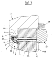
- the electronic circuit 41 may also be equipped with means muting constituted for example by a cut-off switch 44 magnet associated with a magnet 45 fixed on the horizontal bar upper frame 2.
- This switch 41 can be installed on a line connecting the power supply of the electronic circuit 41 or on a link line of this circuit to the siren 42 and the transmitter 43.
- the electronic circuit 41 can also be equipped means for reactivating them after a predetermined time following the closing of the switch 44 following the closure of the In a variant, after having been reactivated, the circuit electronics 41 can advantageously perform a measurement of the capacity of the capacitive detector 24 to constitute a new value of reference.
- the electronic circuit 41 performs a measurement of the detector capacity capacitive 24 to constitute a new reference value.
- the electronic circuit 41 may have means known per se adapted and programmed to fulfill the provisions described above.
- spacers 46 are interposed between the face 4 of the door 1 and the head 11a of the fixing screws 11, to the through passages 10 of the branch 9 of the profile 7 and the springs 47 are interposed between the head of the fastening screws 11 and the facing face vis-à-vis of this branch 9 of the section 7.
- the springs 47 constitute recall members towards the face 4 of the door 1 of the profiles 7 and 12 when they are taken off this face, up to a certain limit.
- the burglar alarm could be installed on the door frame, a short distance from the periphery of his external face and the associated electronic housing fixed on the face interior of a wall adjacent to the door.
Landscapes
- Physics & Mathematics (AREA)
- General Physics & Mathematics (AREA)
- Burglar Alarm Systems (AREA)
Abstract
Description
- la figure 1 représente une vue frontale d'un ouvrant équipé d'un dispositif anti-effraction selon l'invention ;
- la figure 2 représente une coupe transversale du dispositif anti-effraction précité ;
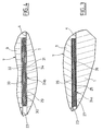
- la figure 3 représente une coupe transversale d'un détecteur capacitif selon l'invention ;
- la figure 4 représente une coupe transversale d'un autre détecteur capacitif selon l'invention ;
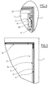
- la figure 5 représente une vue frontale d'une partie dispositif anti-effraction, couvercle enlevé ;
- la figure 6 représente une vue frontale agrandie d'un coin du dispositif anti-effraction, couvercle enlevé ;
- la figure 7 représente une coupe transversale d'une partie supérieure du dispositif anti-effraction précité ;
- la figure 8 représente un schéma électronique du dispositif anti-effraction précité ;
- et la figure 9 représente une coupe transversale du dispositif anti-effraction précité ;.
Claims (24)
- Dispositif anti-effraction pour un ouvrant tel qu'une porte, une fenêtre ou un volet, susceptible d'être fixé sur une surface de réception située en particulier dans le voisinage d'au moins une partie de la périphérie de l'ouvrant, caractérisé par le fait qu'il comprend
un élément allongé (6) présentant une surface d'appui tournée vers ladite surface de réception ;
des moyens (11) pour maintenir cet élément allongé sur ladite surface de réception en des endroits espacés les uns par rapport aux autres ;
et des moyens de détection capacitive (24) interposés entre ladite surface de réception et ladite surface d'appui dudit élément allongé et adaptés pour subir des variations de capacité lorsque la distance entre cette surface de réception et cette surface d'appui varie et délivrer un signal correspondant. - Dispositif selon la revendication 1, caractérisé par le fait que lesdits moyens de détection capacitive comprennent au moins une partie métallique allongée de l'élément allongé et au moins une armature métallique allongée (25) placée dans le voisinage de cette partie métallique et fixée sur ladite surface de réception de l'ouvrant.
- Dispositif selon la revendication 2, caractérisé par le fait que ladite au moins une armature métallique est fixée sur ladite surface de réception de l'ouvrant par un premier ruban adhésif (26) et est fixée sur ladite surface d'appui de l'élement allongé par un second ruban adhésif (28), la résistance à l'arrachement dudit premier ruban adhésif étant supérieure à la résistance à l'arrachement dudit second ruban adhésif.
- Dispositif selon l'une quelconque des revendications précédentes, caractérisé par le fait que lesdits moyens de détection capacitive comprennent au moins deux armatures métalliques allongées (31, 32) placées dans le voisinage l'une de l'autre et dont l'une est fixée sur ladite surface de réception de l'ouvrant et l'autre est fixée sur ladite surface d'appui de l'élément allongé.
- Dispositif selon la revendication 4, caractérisé par le fait que lesdites au moins deux armatures métalliques sont disposées à distance entre deux bandes isolantes repliées de façon à placer ces armatures dans le voisinage l'une de l'autre.
- Dispositif selon l'une des revendications 4 et 5, caractérisé par le fait que l'une desdites armatures est plus large que l'autre.
- Dispositif selon l'une quelconque des revendications 4 à 6, caractérisé par le fait que l'armature solidaire dudit élément allongé est plus large que celle fixée sur l'ouvrant.
- Dispositif selon l'une quelconque des revendications 2 à 7, caractérisé par le fait que ladite au moins une armature métallique comprend au moins un ruban métallique.
- Dispositif selon l'une quelconque des revendications 2 à 7, caractérisé par le fait que ladite au moins une armature métallique comprend au moins un fil métallique.
- Dispositif selon l'une quelconque des revendications précédentes, caractérisé par le fait que ledit élément allongé est tubulaire et que des moyens de connexion extérieure (35) desdits moyens de détection capacitive s'étendent dans cet élément allongé tubulaire.
- Dispositif selon la revendication 10, caractérisé par le fait que lesdits moyens de connexion extérieure traversent l'ouvrant.
- Dispositif selon l'une quelconque des revendications précédentes, caractérisé par le fait que ledit élément allongé comprend une embase allongée (7) maintenue sur ledit ouvrant et un couvercle allongé (12) fixé sur l'embase, les moyens de maintien de l'embase étant caché par le couvercle et les moyens de fixation du couvercle sur l'embase étant cachés lorsque l'ouvrant est en position fermée.
- Dispositif selon la revendication 12, caractérisé par le fait que ladite embase (7) comprend un profilé de base de section en forme de L dont une première branche est fixée sur l'ouvrant par des vis espacées la traversant et ledit couvercle (12) comprend un profilé de recouvrement en prise avec l'extrémité de cette première branche et en appui sur l'extrémité de la seconde branche, des vis traversant la seconde branche du profilé de base et étant en prise dans une fente allongée du profilé de recouvrement.
- Dispositif selon l'une quelconque des revendications précédentes, caractérisé par le fait que ladite surface d'appui de l'élément allongé présente un évidement dans lequel sont logés lesdits moyens de détection capacitive.
- Dispositif selon l'une quelconque des revendications précédentes, caractérisé par le fait que ledit élément allongé est fixé sur ladite surface de réception par l'intermédiaire de moyens à ressort agissant dans le sens de l'appui de cet élément allongé sur cette surface de réception.
- Dispositif selon l'une quelconque des revendications précédentes, caractérisé par le fait qu'il est fixé sur une surface d'appui de l'ouvrant de façon à s'étendre à proximité d'au moins une partie fixe adjacente à cet ouvrant.
- Dispositif selon l'une quelconque des revendications précédentes, caractérisé par le fait qu'il est fixé sur une surface d'appui d'au moins une partie fixe adjacente à l'ouvrant de façon à s'étendre à proximité de ce dernier.
- Dispositif selon l'une quelconque des revendications précédentes, caractérisé par le fait que lesdits moyens de détection capacitive sont reliés à des moyens de traitement électroniques (41) adaptés pour délivrer un signal d'alarme lorsque la variation de la capacité desdits moyens de détection capacitive est supérieure à un seuil prédéterminé.
- Dispositif selon la revendication 18, caractérisé par le fait que lesdits moyens de traitement électroniques comprennent des moyens d'adaptation de la valeur dudit seuil.
- Dispositif selon la revendication 18, caractérisé par le fait qu'il comprend des moyens d'inhibition (44, 45) desdits moyens de traitement et/ou dudit signal d'alarme lorsque l'ouvrant est écarté de sa position fermée d'au moins une distance prédéterminée.
- Dispositif selon la revendication 20, caractérisé par le fait que lesdits moyens d'inhibition comprennent un interrupteur changeant d'état lorsque l'ouvrant est écarté de sa position fermée d'au moins une distance prédéterminée.
- Dispositif selon la revendication 20, caractérisé par le fait que lesdits moyens d'inhibition comprennent un interrupteur de coupure de l'alimentation électrique desdits moyens de traitement lorsque l'ouvrant est écarté de sa position fermée d'au moins une distance prédéterminée.
- Dispositif selon la revendication 20, caractérisé par le fait que lesdits moyens d'inhibition comprennent un interrupteur de coupure de la ligne délivrant ledit signal d'alarme.
- Dispositif selon l'une quelconque des revendications 20 à 23, caractérisé par le fait que lesdits moyens de traitement sont réactivés au bout d'un délai prédéterminé suivant la désactivation desdits moyens d'inhibition.
Applications Claiming Priority (2)
| Application Number | Priority Date | Filing Date | Title |
|---|---|---|---|
| FR0402208 | 2004-03-03 | ||
| FR0402208A FR2867295B1 (fr) | 2004-03-03 | 2004-03-03 | Dispositif anti-effraction d'ouvrant |
Publications (2)
| Publication Number | Publication Date |
|---|---|
| EP1571633A1 true EP1571633A1 (fr) | 2005-09-07 |
| EP1571633B1 EP1571633B1 (fr) | 2008-06-11 |
Family
ID=34746486
Family Applications (1)
| Application Number | Title | Priority Date | Filing Date |
|---|---|---|---|
| EP20050290459 Expired - Lifetime EP1571633B1 (fr) | 2004-03-03 | 2005-03-02 | Dispositif anti-effraction d'ouvrant |
Country Status (3)
| Country | Link |
|---|---|
| EP (1) | EP1571633B1 (fr) |
| DE (1) | DE602005007400D1 (fr) |
| FR (1) | FR2867295B1 (fr) |
Cited By (4)
| Publication number | Priority date | Publication date | Assignee | Title |
|---|---|---|---|---|
| FR2897185A1 (fr) * | 2006-02-07 | 2007-08-10 | Roctool Soc Par Actions Simpli | Dispositif de detection de tentative d'effraction subie par un ouvrant monte mobile par rapport a un dormant |
| WO2008102064A1 (fr) * | 2007-02-16 | 2008-08-28 | Roctool | Dispositif de detection de tentative d'effraction subie par un ouvrant monte mobile par rapport a un dormant |
| CN102561903A (zh) * | 2012-02-11 | 2012-07-11 | 王学章 | 多功能智能式防盗安全门 |
| WO2019007882A1 (fr) * | 2017-07-05 | 2019-01-10 | Koblensky Damien | Procede et dispositif de detection d'intrusions |
Families Citing this family (1)
| Publication number | Priority date | Publication date | Assignee | Title |
|---|---|---|---|---|
| FR3139150B1 (fr) * | 2022-08-29 | 2025-04-18 | Hutchinson | Menuiserie avec detection de la position de l’ouvrant par rapport au dormant |
Citations (2)
| Publication number | Priority date | Publication date | Assignee | Title |
|---|---|---|---|---|
| DE3501884A1 (de) * | 1985-01-22 | 1986-07-24 | BONI oHG Behrens & Otto, 2390 Flensburg | Einbruchsicherungsanlage |
| US5712621A (en) * | 1996-06-06 | 1998-01-27 | Andersen; James D. | Security system with variable inductance sensor |
-
2004
- 2004-03-03 FR FR0402208A patent/FR2867295B1/fr not_active Expired - Fee Related
-
2005
- 2005-03-02 EP EP20050290459 patent/EP1571633B1/fr not_active Expired - Lifetime
- 2005-03-02 DE DE200560007400 patent/DE602005007400D1/de not_active Expired - Fee Related
Patent Citations (2)
| Publication number | Priority date | Publication date | Assignee | Title |
|---|---|---|---|---|
| DE3501884A1 (de) * | 1985-01-22 | 1986-07-24 | BONI oHG Behrens & Otto, 2390 Flensburg | Einbruchsicherungsanlage |
| US5712621A (en) * | 1996-06-06 | 1998-01-27 | Andersen; James D. | Security system with variable inductance sensor |
Cited By (6)
| Publication number | Priority date | Publication date | Assignee | Title |
|---|---|---|---|---|
| FR2897185A1 (fr) * | 2006-02-07 | 2007-08-10 | Roctool Soc Par Actions Simpli | Dispositif de detection de tentative d'effraction subie par un ouvrant monte mobile par rapport a un dormant |
| WO2008102064A1 (fr) * | 2007-02-16 | 2008-08-28 | Roctool | Dispositif de detection de tentative d'effraction subie par un ouvrant monte mobile par rapport a un dormant |
| CN102561903A (zh) * | 2012-02-11 | 2012-07-11 | 王学章 | 多功能智能式防盗安全门 |
| WO2019007882A1 (fr) * | 2017-07-05 | 2019-01-10 | Koblensky Damien | Procede et dispositif de detection d'intrusions |
| FR3068814A1 (fr) * | 2017-07-05 | 2019-01-11 | Damien Koblensky | Procede et dispositif de detection d'intrusions |
| US20200168061A1 (en) * | 2017-07-05 | 2020-05-28 | Damien Koblensky | Method and device for detecting intrusions |
Also Published As
| Publication number | Publication date |
|---|---|
| DE602005007400D1 (de) | 2008-07-24 |
| FR2867295B1 (fr) | 2006-05-19 |
| FR2867295A1 (fr) | 2005-09-09 |
| EP1571633B1 (fr) | 2008-06-11 |
Similar Documents
| Publication | Publication Date | Title |
|---|---|---|
| US6788203B1 (en) | Mailbox and counter combination device | |
| EP1464035A1 (fr) | Systemes detecteurs de securite hertziens pour fenetres et portes | |
| EP2055872B1 (fr) | Armoire formant vitrine avec verrouillage pour au moins une vitre coulissante | |
| WO2010040959A1 (fr) | Dispositif de detection de la presence d'un objet ou d'un etre vivant | |
| EP1571633B1 (fr) | Dispositif anti-effraction d'ouvrant | |
| EP2216478A2 (fr) | Procédé de détection de la présence d'un élément entre un seuil d'une ouverture et une extrémité d'un écran domotique motorisé | |
| EP0245682A2 (fr) | Dispositif de commande d'un appareil électrique d'alarme | |
| FR2809279A1 (fr) | Habillage pour une antenne d'appareil de detection d'objets, et appareil de detection comportant une antenne equipee d'un tel habillage | |
| EP1245774B1 (fr) | Volet roulant motorisé à commande d'arrêt sur obstacle du moteur | |
| FR2950644A1 (fr) | Dispositif de renforcement pour un acces d'un local protege | |
| EP1234088A1 (fr) | Dispositif anti-effraction d'ouvrant | |
| FR3067580B1 (fr) | Boite de commercialisation d'un produit, vitrine commerciale associee et dispositif de commercialisation associe | |
| EP3707329B1 (fr) | Ensemble de fermeture de porte a verrouillage électromagnétique | |
| EP1245779B1 (fr) | Volet roulant dont le tablier intégre un dispositif de détection, notamment d'obstacle et/ou d'effraction | |
| EP3709277B1 (fr) | Élément de système d'alarme | |
| FR2824103A3 (fr) | Moustiquaire avec dispositif de blocage dans l'encadrement d'une porte ou d'une fenetre | |
| EP2784761B1 (fr) | Coffret électronique muni d'un organe de détection d'arrachement | |
| WO2002031299A1 (fr) | Equipment antivol | |
| FR2897185A1 (fr) | Dispositif de detection de tentative d'effraction subie par un ouvrant monte mobile par rapport a un dormant | |
| FR2621349A1 (fr) | Dispositif electromagnetique de maintien en position fermee d'un panneau ouvrant | |
| EP3663502B1 (fr) | Système de détection d'effraction autonome et communiquant pour un volet roulant | |
| EP2018462B1 (fr) | Porte a rideau souple avec boitier de commande precable | |
| EP0898037B1 (fr) | Dispositif d'entraínement motorisé à commande à distance pour porte de garage | |
| EP1914349A1 (fr) | Dispositifs et ensemble de fermeture temporaire d'un passage piétonnier tel qu'un couloir | |
| EP2122592A1 (fr) | Dispositif de detection de tentative d'effraction subie par un ouvrant monte mobile par rapport a un dormant |
Legal Events
| Date | Code | Title | Description |
|---|---|---|---|
| PUAI | Public reference made under article 153(3) epc to a published international application that has entered the european phase |
Free format text: ORIGINAL CODE: 0009012 |
|
| AK | Designated contracting states |
Kind code of ref document: A1 Designated state(s): AT BE BG CH CY CZ DE DK EE ES FI FR GB GR HU IE IS IT LI LT LU MC NL PL PT RO SE SI SK TR |
|
| AX | Request for extension of the european patent |
Extension state: AL BA HR LV MK YU |
|
| 17P | Request for examination filed |
Effective date: 20060111 |
|
| AKX | Designation fees paid |
Designated state(s): DE FR GB IT |
|
| 17Q | First examination report despatched |
Effective date: 20070202 |
|
| RIC1 | Information provided on ipc code assigned before grant |
Ipc: G08B 13/08 20060101AFI20070629BHEP Ipc: G08B 13/06 20060101ALI20070629BHEP |
|
| GRAP | Despatch of communication of intention to grant a patent |
Free format text: ORIGINAL CODE: EPIDOSNIGR1 |
|
| GRAS | Grant fee paid |
Free format text: ORIGINAL CODE: EPIDOSNIGR3 |
|
| GRAA | (expected) grant |
Free format text: ORIGINAL CODE: 0009210 |
|
| AK | Designated contracting states |
Kind code of ref document: B1 Designated state(s): DE FR GB IT |
|
| REG | Reference to a national code |
Ref country code: GB Ref legal event code: FG4D Free format text: NOT ENGLISH |
|
| REF | Corresponds to: |
Ref document number: 602005007400 Country of ref document: DE Date of ref document: 20080724 Kind code of ref document: P |
|
| PLBE | No opposition filed within time limit |
Free format text: ORIGINAL CODE: 0009261 |
|
| STAA | Information on the status of an ep patent application or granted ep patent |
Free format text: STATUS: NO OPPOSITION FILED WITHIN TIME LIMIT |
|
| 26N | No opposition filed |
Effective date: 20090312 |
|
| GBPC | Gb: european patent ceased through non-payment of renewal fee |
Effective date: 20090302 |
|
| REG | Reference to a national code |
Ref country code: FR Ref legal event code: ST Effective date: 20091130 |
|
| PG25 | Lapsed in a contracting state [announced via postgrant information from national office to epo] |
Ref country code: DE Free format text: LAPSE BECAUSE OF NON-PAYMENT OF DUE FEES Effective date: 20091001 |
|
| PG25 | Lapsed in a contracting state [announced via postgrant information from national office to epo] |
Ref country code: FR Free format text: LAPSE BECAUSE OF NON-PAYMENT OF DUE FEES Effective date: 20091123 Ref country code: GB Free format text: LAPSE BECAUSE OF NON-PAYMENT OF DUE FEES Effective date: 20090302 |
|
| PG25 | Lapsed in a contracting state [announced via postgrant information from national office to epo] |
Ref country code: IT Free format text: LAPSE BECAUSE OF NON-PAYMENT OF DUE FEES Effective date: 20090302 |