EP1571518A1 - Sous-ensemble chauffant amovible adapté à être positionné sur le corps principal d'un appareil de cuisson - Google Patents
Sous-ensemble chauffant amovible adapté à être positionné sur le corps principal d'un appareil de cuisson Download PDFInfo
- Publication number
- EP1571518A1 EP1571518A1 EP05290427A EP05290427A EP1571518A1 EP 1571518 A1 EP1571518 A1 EP 1571518A1 EP 05290427 A EP05290427 A EP 05290427A EP 05290427 A EP05290427 A EP 05290427A EP 1571518 A1 EP1571518 A1 EP 1571518A1
- Authority
- EP
- European Patent Office
- Prior art keywords
- switch
- thermostat
- main body
- safety member
- heating
- Prior art date
- Legal status (The legal status is an assumption and is not a legal conclusion. Google has not performed a legal analysis and makes no representation as to the accuracy of the status listed.)
- Withdrawn
Links
- 238000010438 heat treatment Methods 0.000 title claims abstract description 44
- 238000010411 cooking Methods 0.000 title description 2
- 210000000056 organ Anatomy 0.000 description 14
- 235000021168 barbecue Nutrition 0.000 description 4
- 230000001105 regulatory effect Effects 0.000 description 3
- 238000005485 electric heating Methods 0.000 description 2
- 235000013305 food Nutrition 0.000 description 2
- 239000012212 insulator Substances 0.000 description 2
- 239000000470 constituent Substances 0.000 description 1
- 230000010354 integration Effects 0.000 description 1
- 230000005855 radiation Effects 0.000 description 1
- 229910052709 silver Inorganic materials 0.000 description 1
- 239000004332 silver Substances 0.000 description 1
Images


Classifications
-
- H—ELECTRICITY
- H01—ELECTRIC ELEMENTS
- H01H—ELECTRIC SWITCHES; RELAYS; SELECTORS; EMERGENCY PROTECTIVE DEVICES
- H01H89/00—Combinations of two or more different basic types of electric switches, relays, selectors and emergency protective devices, not covered by any single one of the other main groups of this subclass
- H01H89/04—Combination of a thermally actuated switch with a manually operated switch
-
- A—HUMAN NECESSITIES
- A47—FURNITURE; DOMESTIC ARTICLES OR APPLIANCES; COFFEE MILLS; SPICE MILLS; SUCTION CLEANERS IN GENERAL
- A47J—KITCHEN EQUIPMENT; COFFEE MILLS; SPICE MILLS; APPARATUS FOR MAKING BEVERAGES
- A47J37/00—Baking; Roasting; Grilling; Frying
- A47J37/06—Roasters; Grills; Sandwich grills
- A47J37/067—Horizontally disposed broiling griddles
- A47J37/0676—Horizontally disposed broiling griddles electrically heated
-
- G—PHYSICS
- G05—CONTROLLING; REGULATING
- G05D—SYSTEMS FOR CONTROLLING OR REGULATING NON-ELECTRIC VARIABLES
- G05D23/00—Control of temperature
- G05D23/19—Control of temperature characterised by the use of electric means
- G05D23/1927—Control of temperature characterised by the use of electric means using a plurality of sensors
- G05D23/1928—Control of temperature characterised by the use of electric means using a plurality of sensors sensing the temperature of one space
-
- G—PHYSICS
- G05—CONTROLLING; REGULATING
- G05D—SYSTEMS FOR CONTROLLING OR REGULATING NON-ELECTRIC VARIABLES
- G05D23/00—Control of temperature
- G05D23/19—Control of temperature characterised by the use of electric means
- G05D23/275—Control of temperature characterised by the use of electric means with sensing element expanding, contracting, or fusing in response to changes of temperature
-
- H—ELECTRICITY
- H01—ELECTRIC ELEMENTS
- H01H—ELECTRIC SWITCHES; RELAYS; SELECTORS; EMERGENCY PROTECTIVE DEVICES
- H01H37/00—Thermally-actuated switches
- H01H37/02—Details
- H01H37/04—Bases; Housings; Mountings
- H01H37/043—Mountings on controlled apparatus
Definitions
- the present invention relates to a subset removable heater that is adapted to be positioned on a main body of a cooking appliance.
- the electrical circuit supply of the heating element includes, as safety organ, a microswitch that is placed at inside the electrical housing of the subassembly heating and which, by default, cuts the power supply.
- the main body includes an actuating tab which is adapted to penetrate the housing and drive the micro switch in its closed position only when the heating subassembly is correctly positioned.
- the problem is to make a subset heating having no micro-switch safety while meeting the security requirements for feeding the heating element.
- the heating subassembly of the type above includes a thermostat that includes, contactors adapted to connect it to the electrical circuit supply of the heating element, a switch of mobile thermal regulation between an open position and a closed position, and a second switch that is in series with the thermal regulation switch and which includes a first blade in electrical contact with one of the contactors, and a second blade in contact with the thermal regulation switch, at at least one of the two blades being flexible between a position in contact with the other blade, and a position without contact, the second switch being formed only by the two blades, and the safety organ cooperating with this second switch so that when the security organ is in its closed position, the second switch is closed, and when the safety organ is in its position opening, the second switch is open.
- the microswitch is removed and it is replaced by a second switch located in the thermostat.
- the problem of its mounting in the housing of the heating subassembly and that of the wiring is removed: everything is integrated in the thermostat.
- the additional cost of the integration of the second switch is very weak seen that this switch is formed by only two blades conductive.
- the second switch is not a thermal regulation switch (the blades that are not bimetallic).
- the device appliance 1 (in this case an electric barbecue 1) comprises a main body 2, a grid (not shown) detachable positioned on the main body 2 and adapted to receive a food to cook, a heating subassembly 4 detachable positioned on the main body 2 and under the grate and adapted to transmit heat to the food at bake, and a removable thermal reflector 5 positioned in the main body 2 and adapted to return the thermal radiation emitted by the heating subassembly 4 towards the main body 2 towards the grid.
- a grid not shown
- the heating subassembly 4 detachable positioned on the main body 2 and under the grate and adapted to transmit heat to the food at bake
- a removable thermal reflector 5 positioned in the main body 2 and adapted to return the thermal radiation emitted by the heating subassembly 4 towards the main body 2 towards the grid.
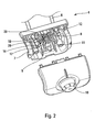
- the heating subassembly 4 comprises a body of 6 (in this case, an electrical resistance of heater 6), a housing 7 inside which are arranged the different elements of control and regulation of the power supply of the electric heating element 6. Among these elements of control and regulation, there is a thermostat 8 and a safety device 9. In addition, the heating subassembly 4 also includes a button manual control 10 allowing a user to act on the thermostat 8 and thus regulate the power supply of the electric heating resistance 6.
- the thermostat 8 includes two contactors 11, 12 which allow to connect the thermostat 8 to the electrical circuit of the power supply of the electrical resistance 6. It includes also a thermal regulation switch 13 which is movable between an open position and a position closed, and a second switch 14 which is mounted in series with thermal regulation switch 13.
- the regulation switch 13 is formed on the one hand by a tongue 15 and by a spring 16 whose flexibility depends on the position the manual control button 10.
- the second switch 14 is formed by two blades 17,18: a first blade 17 which is in electrical contact with one of the two contactors 11,12, and a second blade 18 which is electrical contact with the regulation switch 13.
- the two blades 17, 18 are flexible so to be able to move between a contact position in which they are in contact with each other, and a position in which they are not in contact.
- the flexible blades 17, 18 are deformable elastically and they are arranged so as to be naturally in their position without contact.
- the second switch 14 is not a regulating switch thermal, it is a switch that is formed only by the two conductive blades 17,18.
- both 17,18 blades are provided, at their free end, with a point 19.20 in silver.
- the stacking of insulators and conductive elements in the thermostat 8 is the following: a first insulating ring 21, a first blade 17 of the second switch 14, the first contactor 11 allowing the electrical connection of the thermostat 8 (in electrical contact with the first 17), a second insulating ring 22, the second blade 18 of the second switch 14, the spring 16 of the thermal regulation switch 13 (in contact electric with the second blade 18), a third ring insulator 23, the tab 15 of the regulation switch 13, the second contactor 12 allowing the electrical connection of thermostat 8 (in electrical contact with the tongue 15), a fourth insulating ring 25, and one bimetallic 40.
- the thermostat 8 when the two blades 17, 18 are in contact with one another with the other, the thermostat 8 is equivalent to a conventional thermostat: when spring 16 is in contact with tab 15, the control switch thermal 13 is closed and the electric current can circulate through the thermostat 8, and when the spring 16 no longer in contact with the tab 15, the switch of thermal regulation 13 is open and the current no longer circulates through thermostat 8. the mobility of the spring 16 being due to the deformation of the bimetallic 40 depending on the surrounding temperature, bimetallic strip 40 to which the spring 16 is connected by through the board 41.
- the safety member 9 is movable between a position opening and a closed position and cooperates with the second switch 14 of the thermostat 8 so that, when the security organ 9 is in its position of closing, the second switch 14 is closed, and when the safety member 9 is in its open position, the second switch 14 is open.
- the security organ 9 comprises a drive finger 28 adapted to enter into contact with a training surface 29 carried by the second switch 14 so as to cause the second switch 14 in its closed position when the organ security 9 is in its closed position.
- the training surface 29 is carried by one of the two flexible blades 17,18 of the second switch 14.
- the security organ 9 is a mobile monobloc part. It is pivotally mounted in the housing 7 around an axis of rotation.
- the main body 2 of the barbecue 1 has a finger actuator 30 which is adapted to contact and to move an actuating tab 31 carried by the organ of safety 9 so as to cause the latter in its position when the heating subassembly 4 is correctly positioned on the main body 2.
- the safety member 9 is in its position opening (and because of this, the second switch 14 is open, which prevents any power supply from electrical resistance 6)
- the actuating finger 30 has led the leg actuator 31 and the entire safety member 9 in its closed position (and because of this, the second switch 14 is closed, the power supply of the electrical resistance 6 can then be regulated by the thermostat 8).
- the heating subassembly 4 in use, if the heating subassembly 4 is located off the main body, even though the button manual control 10 is actuated, the heater 6 does not can not be powered. If the heating subassembly 4 is correctly positioned, feeding the organ of 6 heater can be regulated by pressing the button manual control 10. If the heating subassembly 4 is removed from the main body 2 while the heating member 6 is powered, the actuating finger 30 no longer acts on the actuating tab 31 and the elasticity of the blades 17, 18 of the second switch 14 causes their setting in position without contact and rotation of the safety organ towards its opening position.
- the thermal reflector 5 comprises an element of support of the resistor 6 which makes it possible to position horizontally this one. If the thermal reflector 5 is not correctly placed on main body 2 (or if not present), the heating subassembly 4 pivots inside the main body 2 and thus the housing 7 pivots upwards and away from the finger actuator 30 of the main body 2. As a result, the actuating finger 30 can not cooperate with the leg actuator 31 and the safety member 9 is not driven in its closed position.
Landscapes
- Engineering & Computer Science (AREA)
- Physics & Mathematics (AREA)
- General Physics & Mathematics (AREA)
- Automation & Control Theory (AREA)
- Food Science & Technology (AREA)
- Control Of Resistance Heating (AREA)
Abstract
Description
Claims (8)
- Thermostat (8) comprenant des contacteurs (11,12) adaptés à relier le thermostat (8) à un circuit électrique, un interrupteur de régulation thermique (13) mobile entre une position ouverte et une position fermée, et un deuxième interrupteur (14) qui est monté en série avec l'interrupteur de régulation thermique (13) et qui comprend une première lame (17) en contact électrique avec l'un (11) des contacteurs (11,12), et une deuxième lame (18) en contact électrique avec l'interrupteur de régulation thermique (13), au moins une des deux lames (17,18) étant flexible entre une position en contact avec l'autre lame, et une position sans contact, caractérisé en ce que le deuxième interrupteur (14) n'est formé que par les deux lames (17,18).
- Thermostat (8) selon la revendication 1, caractérisé en ce que la lame flexible est déformable élastiquement et agencée de façon à être naturellement sans contact avec l'autre lame.
- Sous-ensemble chauffant (4) comportant un organe de sécurité (9) mobile entre une position d'ouverture et une position de fermeture, et un thermostat (8), caractérisé en ce que le thermostat (8) est conforme à la revendication 1 ou 2, l'organe de sécurité (9) coopérant avec le deuxième interrupteur (14) du thermostat (8) de sorte que, quand l'organe de sécurité (9) est dans sa position de fermeture, le second interrupteur (14) est fermé, et quand l'organe de sécurité (9) est dans sa position d'ouverture, le second interrupteur (14) est ouvert.
- Sous-ensemble chauffant (4) selon la revendication 3, caractérisé en ce que l'organe de sécurité (9) comporte un doigt d'entraínement (28) adapté à entrer en contact avec une surface d'entraínement (29) portée par le second interrupteur (14) de façon à entraíner le second interrupteur (14) dans sa position fermée quand l'organe de sécurité (9) est dans sa position de fermeture.
- Sous-ensemble chauffant (4) selon la revendication 4, caractérisé en ce que la surface d'entraínement (29) est portée par la lame flexible du thermostat (8) .
- Sous-ensemble chauffant (4) selon l'une des revendications 3 à 5, caractérisé en ce que l'organe de sécurité (9) est une pièce monobloc montée de façon pivotante dans le sous-ensemble chauffant (4).
- Appareil électroménager (1) comprenant un corps principal (2) qui possède un doigt d'actionnement (30), et un sous-ensemble chauffant (4) amovible adapté à être positionné sur le corps principal (2), caractérisé en ce que le sous-ensemble chauffant (4) est conforme à l'une des revendications 3 à 6, le doigt d'actionnement (30) étant adapté à coopérer avec une patte d'actionnement (31) portée par l'organe de sécurité (9), de sorte que, quand le sous-ensemble chauffant (4) est correctement positionné sur le corps principal (2), l'organe de sécurité (9) est dans sa position de fermeture sous l'action le doigt d'actionnement (30), et quand le sous-ensemble chauffant (4) est séparé du corps principal (2), l'organe de sécurité (9) est dans sa position d'ouverture.
- Appareil électroménager (1) selon la revendication 7, caractérisé en ce qu'il comprend un réflecteur thermique (5) amovible qui est adapté à être positionné dans le corps principal (2) et qui comprend un élément de support qui est adapté à coopérer avec le sous-ensemble chauffant (4), de sorte que, quand le réflecteur (5) est hors du corps principal (2), le doigt d'actionnement (30) ne peut pas entraíner l'organe de sécurité (9) dans sa position de fermeture.
Applications Claiming Priority (2)
| Application Number | Priority Date | Filing Date | Title |
|---|---|---|---|
| FR0402193A FR2867345B1 (fr) | 2004-03-03 | 2004-03-03 | Sous-ensemble chauffant amovible adapte a etre positionne sur le corps principal d'un appareil de cuisson |
| FR0402193 | 2004-03-03 |
Publications (1)
| Publication Number | Publication Date |
|---|---|
| EP1571518A1 true EP1571518A1 (fr) | 2005-09-07 |
Family
ID=34746485
Family Applications (1)
| Application Number | Title | Priority Date | Filing Date |
|---|---|---|---|
| EP05290427A Withdrawn EP1571518A1 (fr) | 2004-03-03 | 2005-02-24 | Sous-ensemble chauffant amovible adapté à être positionné sur le corps principal d'un appareil de cuisson |
Country Status (2)
| Country | Link |
|---|---|
| EP (1) | EP1571518A1 (fr) |
| FR (1) | FR2867345B1 (fr) |
Citations (4)
| Publication number | Priority date | Publication date | Assignee | Title |
|---|---|---|---|---|
| GB526906A (en) * | 1938-04-14 | 1940-09-27 | Proctor & Schwartz Inc | Improvements in or relating to the control of electrical cooking apparatus |
| FR2249424A1 (en) * | 1973-10-24 | 1975-05-23 | Debare Jacques | Thermostatic control device for electric heater - temp. range of one switch is within temp. range of second switch |
| US5504295A (en) * | 1993-03-30 | 1996-04-02 | Moulinex S.A. | Electric cooking apparatus |
| EP0802547A2 (fr) * | 1994-05-06 | 1997-10-22 | Seb S.A. | Dispositif de sécurité pour un élément électrique mobile et barbeque électrique équipé d'un tel dispositif |
-
2004
- 2004-03-03 FR FR0402193A patent/FR2867345B1/fr not_active Expired - Fee Related
-
2005
- 2005-02-24 EP EP05290427A patent/EP1571518A1/fr not_active Withdrawn
Patent Citations (5)
| Publication number | Priority date | Publication date | Assignee | Title |
|---|---|---|---|---|
| GB526906A (en) * | 1938-04-14 | 1940-09-27 | Proctor & Schwartz Inc | Improvements in or relating to the control of electrical cooking apparatus |
| FR2249424A1 (en) * | 1973-10-24 | 1975-05-23 | Debare Jacques | Thermostatic control device for electric heater - temp. range of one switch is within temp. range of second switch |
| US5504295A (en) * | 1993-03-30 | 1996-04-02 | Moulinex S.A. | Electric cooking apparatus |
| EP0802547A2 (fr) * | 1994-05-06 | 1997-10-22 | Seb S.A. | Dispositif de sécurité pour un élément électrique mobile et barbeque électrique équipé d'un tel dispositif |
| US5739493A (en) * | 1994-05-06 | 1998-04-14 | Seb S.A. | Safety device for a mobile electric unit and electric barbecue fitted with this device |
Also Published As
| Publication number | Publication date |
|---|---|
| FR2867345B1 (fr) | 2007-04-13 |
| FR2867345A1 (fr) | 2005-09-09 |
Similar Documents
| Publication | Publication Date | Title |
|---|---|---|
| US6153859A (en) | Liquid heating vessels | |
| US6840802B2 (en) | Combined control/connector for cordless electrical appliances | |
| US6080967A (en) | Combined user actuation and thermostat switch assembly | |
| EP0167429A1 (fr) | Interrupteur multidirectionnel à commande par une bille | |
| EP0617909A1 (fr) | Appareil électrique de cuisson | |
| FR2540976A1 (fr) | Dispositif d'entrainement de registre de regulation pour appareil de chauffage ou analogue | |
| US20150144007A1 (en) | Grill Device | |
| FR2484819A1 (fr) | Appareil electrique de chauffage de liquides | |
| EP3040002B1 (fr) | Dispositif de grill | |
| EP1628559B1 (fr) | Appareil electromenager comportant deux sous-ensembles chauffants articules entre eux | |
| EP0248699B1 (fr) | Dispositif de cuisson électrique à haut rendement, plus spécialement destiné à des restaurateurs ou à des collectivités | |
| FR2683895A3 (fr) | Convecteur electrique. | |
| FR2867345A1 (fr) | Sous-ensemble chauffant amovible adapte a etre positionne sur le corps principal d'un appareil de cuisson | |
| EP0623303B1 (fr) | Appareil électrique de cuisson | |
| FR2811006A1 (fr) | Dispositif de blocage de porte, notamment destine a un appareil electromenager | |
| EP0467784B1 (fr) | Fer à repasser électrique à vapeur comprenant une platine regroupant les organes de réglage | |
| EP0657133B1 (fr) | Capteur CTN sur support souple pour gril-viande | |
| EP0743666B1 (fr) | Thermostat de régulation comportant dans la sonde un dispositif de sécurité | |
| EP1703827B1 (fr) | Appareil electromenager du type gaufrier | |
| FR2530110A1 (fr) | Corps chauffant electrique, notamment pour appareils menagers | |
| FR2897421A1 (fr) | Dispositif chauffant regule pour chauffe-eau | |
| FR2593661A1 (fr) | Dispositif interrupteur pour controler l'alimentation d'un appareil de chauffage electrique a une seule resistance. | |
| EP0587046B1 (fr) | Dispositif de commande d'au moins deux voyants lumineux d'indication d'état | |
| EP1767130B1 (fr) | Dispositif de régulation de l'alimentation électrique d'un résistance pour barbecue | |
| GB2336986A (en) | Dual power output liquid heating element arrangement |
Legal Events
| Date | Code | Title | Description |
|---|---|---|---|
| PUAI | Public reference made under article 153(3) epc to a published international application that has entered the european phase |
Free format text: ORIGINAL CODE: 0009012 |
|
| AK | Designated contracting states |
Kind code of ref document: A1 Designated state(s): AT BE BG CH CY CZ DE DK EE ES FI FR GB GR HU IE IS IT LI LT LU MC NL PL PT RO SE SI SK TR |
|
| AX | Request for extension of the european patent |
Extension state: AL BA HR LV MK YU |
|
| 17P | Request for examination filed |
Effective date: 20060128 |
|
| AKX | Designation fees paid |
Designated state(s): AT BE BG CH CY CZ DE DK EE ES FI FR GB GR HU IE IS IT LI LT LU MC NL PL PT RO SE SI SK TR |
|
| 17Q | First examination report despatched |
Effective date: 20120411 |
|
| STAA | Information on the status of an ep patent application or granted ep patent |
Free format text: STATUS: THE APPLICATION IS DEEMED TO BE WITHDRAWN |
|
| 18D | Application deemed to be withdrawn |
Effective date: 20120901 |