EP1571517A1 - Procédé de contrôle de l'amortissement de vibrations d'un hélicoptère et dispositif mettant en oeuvre le procédé - Google Patents
Procédé de contrôle de l'amortissement de vibrations d'un hélicoptère et dispositif mettant en oeuvre le procédé Download PDFInfo
- Publication number
- EP1571517A1 EP1571517A1 EP05004301A EP05004301A EP1571517A1 EP 1571517 A1 EP1571517 A1 EP 1571517A1 EP 05004301 A EP05004301 A EP 05004301A EP 05004301 A EP05004301 A EP 05004301A EP 1571517 A1 EP1571517 A1 EP 1571517A1
- Authority
- EP
- European Patent Office
- Prior art keywords
- damper
- blades
- response
- blade
- rotor
- Prior art date
- Legal status (The legal status is an assumption and is not a legal conclusion. Google has not performed a legal analysis and makes no representation as to the accuracy of the status listed.)
- Granted
Links
- 238000000034 method Methods 0.000 title claims abstract description 25
- 238000013016 damping Methods 0.000 title claims abstract description 16
- 230000004044 response Effects 0.000 claims abstract description 40
- 230000033001 locomotion Effects 0.000 claims description 19
- 238000004458 analytical method Methods 0.000 claims description 11
- 230000005484 gravity Effects 0.000 claims description 10
- 230000008569 process Effects 0.000 claims description 9
- 238000001914 filtration Methods 0.000 claims description 5
- 230000001133 acceleration Effects 0.000 claims description 2
- 230000001131 transforming effect Effects 0.000 claims 1
- 238000006073 displacement reaction Methods 0.000 abstract description 5
- 238000005259 measurement Methods 0.000 abstract 1
- 239000006096 absorbing agent Substances 0.000 description 10
- 230000035939 shock Effects 0.000 description 10
- 230000010355 oscillation Effects 0.000 description 8
- 230000008901 benefit Effects 0.000 description 4
- 230000008878 coupling Effects 0.000 description 3
- 238000010168 coupling process Methods 0.000 description 3
- 238000005859 coupling reaction Methods 0.000 description 3
- 239000012530 fluid Substances 0.000 description 3
- 230000002028 premature Effects 0.000 description 3
- 230000010349 pulsation Effects 0.000 description 3
- 241000940835 Pales Species 0.000 description 2
- 206010033546 Pallor Diseases 0.000 description 2
- 238000004364 calculation method Methods 0.000 description 2
- 230000000694 effects Effects 0.000 description 2
- 238000005457 optimization Methods 0.000 description 2
- 238000005096 rolling process Methods 0.000 description 2
- 230000008859 change Effects 0.000 description 1
- 238000000354 decomposition reaction Methods 0.000 description 1
- 230000001419 dependent effect Effects 0.000 description 1
- 230000005284 excitation Effects 0.000 description 1
- 230000010006 flight Effects 0.000 description 1
- 238000010438 heat treatment Methods 0.000 description 1
- 239000012535 impurity Substances 0.000 description 1
- 230000001939 inductive effect Effects 0.000 description 1
- 238000004519 manufacturing process Methods 0.000 description 1
- 230000003071 parasitic effect Effects 0.000 description 1
- 230000032696 parturition Effects 0.000 description 1
- 238000000926 separation method Methods 0.000 description 1
- 230000006641 stabilisation Effects 0.000 description 1
- 238000011105 stabilization Methods 0.000 description 1
Images


Classifications
-
- B—PERFORMING OPERATIONS; TRANSPORTING
- B64—AIRCRAFT; AVIATION; COSMONAUTICS
- B64C—AEROPLANES; HELICOPTERS
- B64C27/00—Rotorcraft; Rotors peculiar thereto
- B64C27/51—Damping of blade movements
-
- F—MECHANICAL ENGINEERING; LIGHTING; HEATING; WEAPONS; BLASTING
- F16—ENGINEERING ELEMENTS AND UNITS; GENERAL MEASURES FOR PRODUCING AND MAINTAINING EFFECTIVE FUNCTIONING OF MACHINES OR INSTALLATIONS; THERMAL INSULATION IN GENERAL
- F16F—SPRINGS; SHOCK-ABSORBERS; MEANS FOR DAMPING VIBRATION
- F16F9/00—Springs, vibration-dampers, shock-absorbers, or similarly-constructed movement-dampers using a fluid or the equivalent as damping medium
- F16F9/32—Details
- F16F9/53—Means for adjusting damping characteristics by varying fluid viscosity, e.g. electromagnetically
- F16F9/535—Magnetorheological [MR] fluid dampers
-
- G—PHYSICS
- G05—CONTROLLING; REGULATING
- G05D—SYSTEMS FOR CONTROLLING OR REGULATING NON-ELECTRIC VARIABLES
- G05D19/00—Control of mechanical oscillations, e.g. of amplitude, of frequency, of phase
- G05D19/02—Control of mechanical oscillations, e.g. of amplitude, of frequency, of phase characterised by the use of electric means
-
- B—PERFORMING OPERATIONS; TRANSPORTING
- B64—AIRCRAFT; AVIATION; COSMONAUTICS
- B64C—AEROPLANES; HELICOPTERS
- B64C27/00—Rotorcraft; Rotors peculiar thereto
- B64C27/001—Vibration damping devices
- B64C2027/004—Vibration damping devices using actuators, e.g. active systems
-
- Y—GENERAL TAGGING OF NEW TECHNOLOGICAL DEVELOPMENTS; GENERAL TAGGING OF CROSS-SECTIONAL TECHNOLOGIES SPANNING OVER SEVERAL SECTIONS OF THE IPC; TECHNICAL SUBJECTS COVERED BY FORMER USPC CROSS-REFERENCE ART COLLECTIONS [XRACs] AND DIGESTS
- Y10—TECHNICAL SUBJECTS COVERED BY FORMER USPC
- Y10S—TECHNICAL SUBJECTS COVERED BY FORMER USPC CROSS-REFERENCE ART COLLECTIONS [XRACs] AND DIGESTS
- Y10S416/00—Fluid reaction surfaces, i.e. impellers
- Y10S416/50—Vibration damping features
Definitions
- the present invention relates to the technical field of helicopters and more particularly in the field of optimization conditions of use of said helicopters.
- Helicopters have rotors driving blades.
- the rotation of the blades generates on these movements in trainee, known manufacturers.
- the movements in drag cause vibrations, in the form of oscillations, altering the helicopter stability and flying comfort. It is therefore important guarantee the absence of any instability of the helicopter, particular of ground resonance and air resonance, which is explained the principle in the following paragraphs.
- the drag movement also induces in the fuselage longitudinal forces and lateral generators of pitching and rolling movements, as well as parasitic moments in the kinematic chain.
- the helicopter can undergo a coupling phenomenon particular mechanics, called ground resonance in the field aeronautics.
- the fuselage has its own mode of pulsation, and the blades present a specific mode of pulsation of drag.
- the blade movements induce forces on the rotor giving birth to movements of the structure, which have their turn an effect on the movements of the blades. If the frequencies of the fuselage and rotor modes are sufficiently close and if these modes are insufficiently amortized, the drag movements blades and movements of the structure will be amplified mutually and may become dangerous.
- the helicopter In flight, the helicopter can undergo a phenomenon of resonance of the same type as previously described but coming from a coupling between the drag pulse pulsation mode and the pendulum oscillation mode of the fuselage.
- This phenomenon known under the name of air resonance, is usually aggravated by severe flight configurations, such as bends for example, because the strong amplitude of the forced dynamic response of the dampers, imposed by the rotor driving the blades, weakens then their damping characteristics of the response natural, whose frequency is lower than that of the response forced.
- the hub ensuring the connection between the blades and the shaft drive in rotation of the rotor, will have to undergo very important during flight time, resulting in fatigue important and a risk of breakage of mechanical parts. This is eligible for relatively brief flight phases.
- the shock absorbers trainee should therefore dampen vibrations only when they generate instability, for example in configurations of delicate flights of the type turns or others. We can thus reduce heating and therefore the risk of premature wear.
- shock absorbers often have problems with reliability on the one hand, and are very expensive on the other.
- the purpose of the present invention is to remedy the disadvantages of the known shock absorbers, and to control the vibrations generated by the movement of the blades all operational configurations of the helicopter.
- the present invention thus makes it possible to control the phenomena of instability, in particular of ground resonance and air resonance, avoiding premature wear of mechanical parts and dampers.
- the method consists of repeat steps (a) through (d) continuously as long as the blades are in rotation.
- the process consists of using a magneto-rheological damper and control electric supply currents of said damper.
- Step (d) consists, for example, in determining the elongation, the speed or acceleration resulting from these responses, natural and forced, dragged.
- the process consists for example in increasing the depreciation if the product P (t) is positive.
- the method consists in calculating the position of the center of gravity of the blades, determine a distance between the center of gravity of the blades and the axis of the rotor, and to transform this gap, into a signal of control acting on the damper, bringing the center closer together of gravity of the blades of the rotor axis.
- This device has the advantage of being controlled and by therefore easily adjustable to different applications.
- the shock absorbers can be controlled so as to cushion the low frequency vibrations (less than the rotation frequency of the rotor) only when necessary. So there is no dissipation of energy unnecessarily.
- the device comprises a microprocessor controlling the frequency of analysis and control.
- the trailing damper is preferably a shock absorber magneto-rheological.
- Magnetorheological dampers can also be controlled by a current 1 to 2 amps, low voltage (12-24 volts). Its characteristics change with temperature, but this evolution can be compensated by a field adjustment magnetic. The response time of such dampers is by otherwise weak. The passage time to go from 10% to 90% of the force generated by the damper for a given excitation is of 8 milliseconds.
- Another advantage is related to the great simplicity of piloting and control.
- the present invention also relates to a helicopter rotor comprising a device for damping movement by dragging blades, as shown above.
- the drag movements of the blades generate oscillations of two types.
- the first type of oscillations present the same frequency, so-called forced, that of the rotor of the helicopter.
- the second type of oscillation corresponds to oscillations of drag with a natural frequency and amplitude more weak than those of the first type. Both types of oscillations are called, respectively, forced response and natural response blades. These responses are shown schematically in Figure 1 with the curves C1 and C2.
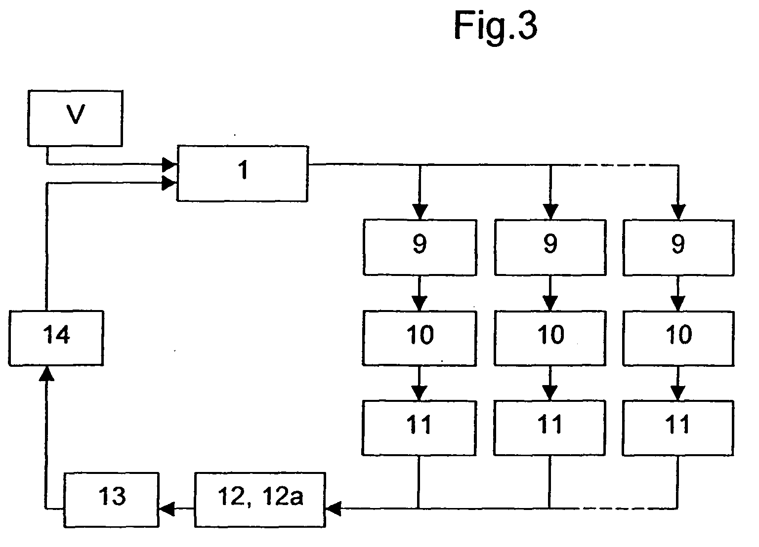
- the control device comprises a trailing damper 1 associated with each blade.
- the damper is preferably a magneto-rheological damper 1, schematized partially in Figure 2.
- the damper 1 has a frame 2, delimiting a first chamber 3 and a second chamber 4.
- the magnetorheological fluid is moved from one chamber to the other and vice versa via a piston 5 moving in the frame 2.
- the piston 5 is actuated by a rod 6 and has dimensions to make a passage 7 for the fluid between the two chambers 3 and 4.
- An electric coil 8 is mounted for example on the periphery of the piston 5 to generate a magnetic field. The operation of such a damper Magnetorheological is already known.
- the control device also comprises a sensor 9 of elongation connected to the trailing damper 1, to measure the displacement of the rod 6 with respect to the armature 2.
- a amplifier 10 of the signal delivered by the sensor 9 can also To be scheduled.
- the device also comprises processing means signal to separate the natural response of drag from the forced response of each blade, associated with means of analysis and control acting on the damper in adjusting its damping characteristics.
- the separation of natural and forced responses is performed by a means of filtering 11 1 to suppress the high frequencies of the response measured.
- the bi-frequency vibrations to which are subjected the blades can thus be separated into a frequency signal forced and a natural frequency signal of weaker drag to using means of signal processing 12.
- the piloting device also comprises means for 12a calculation giving the displacement of the center of gravity of the blades relative to the rotor.
- Electronic processing means 13 are also provided for controlling a voltage generator 14 connected to the trailing damper 1, depending on the results obtained by the calculation means 12a and the processing means 12. These results reflect the V vibrations transmitted to the trailing damper 1.
- the calculating means comprise advantageously a microprocessor. This last driver by example the frequency of analysis and control. Piloting a trailing damper 1, in this case magneto-rheological so does it reliably, fast and accurately.
- the signal from the filtration means 11 1 feeds a unit of decomposition of the signal 15, separating the function corresponding to the forced speed response D '(t) of the function corresponding to the natural response in speed of (t).
- D (t) and (t) are answers in speed as a function of time.
- the device comprises a system of control 17, integrating an electrical current generator connected to the shock absorber 1.
- the control system determines from characteristics of the calculated signal P (t), if the trailing damper 1 must be activated or not.
- the piloting device schematized as an example to FIGS. 3 and 4 thus make it possible to present the method according to the invention according to two modes of implementation.
- the control method of the trailing damper 1 consists in measuring its elongation, amplifying the measured signal and filtering the noise accompanying said signal. Then isolate the natural response of the blade of the forced response. this allows to identify and analyze the vibrations to which the helicopter.
- This gap is then transformed into a signal of control acting on the damper 1, to bring this spread to a low or zero value.
- the process consists for example in increasing the damping if P (t) is positive.
- the trailing magnet 1 magneto-rheological can thus, according to an example of use, only be activated to increase depreciation only in the case of a product P (t) positive.
- the control system 17 operates for example on the principle of all or nothing, ie by inducing a magnetic field maximum or zero in the magneto-rheological damper 1.
Landscapes
- Engineering & Computer Science (AREA)
- Physics & Mathematics (AREA)
- General Engineering & Computer Science (AREA)
- Mechanical Engineering (AREA)
- Electromagnetism (AREA)
- Aviation & Aerospace Engineering (AREA)
- General Physics & Mathematics (AREA)
- Automation & Control Theory (AREA)
- Fluid-Damping Devices (AREA)
- Vibration Prevention Devices (AREA)
Abstract
Description
- (a) mesurer l'élongation de l'amortisseur,
- (b) amplifier le signal mesuré et filtrer le bruit,
- (c) isoler la réponse naturelle de la pale correspondant au mouvement de traínée de la pale, de la réponse forcée imposée par un rotor entraínant les pales,
- (d) et analyser en temps réel les réponses, naturelle et forcée, et ajuster l'amortissement en fonction de cette analyse.
- un amortisseur de traínée associé à chaque pale,
- un capteur d'élongation relié à l'amortisseur,
- un amplificateur pour amplifier les signaux délivrés par le capteur,
- des moyens de traitement du signal pour séparer la réponse naturelle de traínée de la réponse forcée de chaque pale,
- et des moyens d'analyse et de commande agissant sur l'amortisseur en ajustant ses caractéristiques d'amortissement.
- la figure 1 représente des vibrations bi-fréquentielles de pales d'hélicoptère,
- la figure 2 est une représentation schématique partielle d'un amortisseur magnéto-rhéologique utilisé dans le procédé conforme à l'invention,
- la figure 3 schématise un exemple de mise en oeuvre du procédé conforme à l'invention,
- la figure 4 schématise un autre exemple de mise en oeuvre du procédé conforme à l'invention.
Claims (12)
- Procédé de pilotage d'un amortisseur de traínée d'une pale d'hélicoptère et ce, dans toutes les configurations de fonctionnement de l'hélicoptère, consistant à :(a) mesurer l'élongation de l'amortisseur,(b) amplifier le signal mesuré et filtrer le bruit,(c) isoler la réponse naturelle de la pale correspondant au mouvement de traínée de la pale, de la réponse forcée imposée par un rotor entraínant les pales,(d) et analyser en temps réel la réponse naturelle et ajuster l'amortissement en fonction de cette analyse.
- Procédé selon la revendication 1,
caractérisé en ce qu'il consiste à reprendre en continu les étapes (a) à (d), tant que les pales sont en rotation. - Procédé selon la revendication 1 ou 2,
caractérisé en ce qu'il consiste à utiliser un amortisseur magnéto-rhéologique et à commander des courants électriques d'alimentation dudit amortisseur. - Procédé selon l'une quelconque des revendications 1 à 3,
caractérisé en ce que l'étape (d) consiste à déterminer l'élongation, la vitesse ou l'accélération résultant de cette réponse naturelle de traínée. - Procédé selon l'une quelconque des revendications 1 à 3,
caractérisé en ce qu'il consiste à déterminer les fonctions représentatives en fonction du temps de la réponse naturelle de traínée en vitesse d'(t) et de la réponse forcée en vitesse D'(t), à calculer le produit P(t)=D'(t).d'(t), et à déterminer si le produit P(t) est positif ou négatif pour mettre en oeuvre l'étape (d). - Procédé selon la revendication 5,
caractérisé en ce qu'il consiste à augmenter l'amortissement si le produit P(t) est positif. - Procédé selon la revendication 4,
caractérisé en ce qu'il consiste à calculer la position du centre de gravité des pales, à déterminer un écartement entre le centre de gravité des pales et l'axe du rotor, et à transformer cet écartement, en un signal de commande agissant sur l'amortisseur, rapprochant ainsi le centre de gravité des pales de l'axe du rotor. - Dispositif de pilotage de l'amortissement du mouvement en traínée des pales d'un hélicoptère, le dispositif pour mettre en oeuvre le procédé conforme à l'une quelconque des revendications précédentes, comportant :un amortisseur de traínée associé à chaque pale,un capteur d'élongation relié à l'amortisseur,un amplificateur pour amplifier les signaux délivrés par le capteur,des moyens de traitement du signal pour séparer la réponse naturelle de traínée de la réponse forcée de chaque pale,et des moyens d'analyse et de commande agissant sur l'amortisseur en ajustant ses caractéristiques d'amortissement.
- Dispositif selon la revendication 8,
caractérisé en ce qu'il comporte un microprocesseur pilotant la fréquence d'analyse et de commande. - Dispositif selon la revendication 8 ou 9,
caractérisé en ce que l'amortisseur de traínée est un amortisseur magnéto-rhéologique. - Dispositif selon l'une quelconque des revendications 8 à 10,
caractérisé en ce que les moyens d'analyse comprennent des moyens de calcul de la position du centre de gravité des pales à partir des signaux issus de capteurs d'élongation de l'ensemble des pales. - Rotor d'hélicoptère comportant un dispositif d'amortissement du mouvement en traínée des pales, conforme à l'une quelconque des revendications 8 à 11.
Applications Claiming Priority (2)
| Application Number | Priority Date | Filing Date | Title |
|---|---|---|---|
| FR0402169A FR2867152B1 (fr) | 2004-03-03 | 2004-03-03 | Procede de controle de l'amortissement de vibrations d'un helicoptere et dispositif mettant en oeuvre le procede |
| FR0402169 | 2004-03-03 |
Publications (2)
| Publication Number | Publication Date |
|---|---|
| EP1571517A1 true EP1571517A1 (fr) | 2005-09-07 |
| EP1571517B1 EP1571517B1 (fr) | 2007-04-11 |
Family
ID=34746483
Family Applications (1)
| Application Number | Title | Priority Date | Filing Date |
|---|---|---|---|
| EP05004301A Ceased EP1571517B1 (fr) | 2004-03-03 | 2005-02-28 | Procédé de contrôle de l'amortissement de vibrations d'un hélicoptère et dispositif mettant en oeuvre le procédé |
Country Status (3)
| Country | Link |
|---|---|
| US (1) | US7360994B2 (fr) |
| EP (1) | EP1571517B1 (fr) |
| FR (1) | FR2867152B1 (fr) |
Cited By (4)
| Publication number | Priority date | Publication date | Assignee | Title |
|---|---|---|---|---|
| FR2954431A1 (fr) * | 2009-12-23 | 2011-06-24 | Airbus | Dispositif antivibratoire pour un systeme, en particulier de type electrique et/ou electronique, d'un aeronef. |
| FR2954432A1 (fr) * | 2009-12-23 | 2011-06-24 | Airbus | Dispositif antivibratoire pour un systeme generateur de vibrations d'un aeronef. |
| CN101737450B (zh) * | 2010-01-06 | 2012-11-21 | 嘉兴学院 | 智能磁流变减振系统 |
| CN112904718A (zh) * | 2021-01-14 | 2021-06-04 | 吉林大学 | 一种基于Hammerstein模型的磁流变阻尼器控制系统及方法 |
Families Citing this family (6)
| Publication number | Priority date | Publication date | Assignee | Title |
|---|---|---|---|---|
| FR2961333B1 (fr) | 2010-06-14 | 2012-06-08 | Eurocopter France | Procede de surveillance de l'efficacite d'un amortisseur et dispositif pour mettre en oeuvre ledit procede |
| CN102501970B (zh) * | 2011-11-15 | 2014-12-24 | 中国航空工业集团公司北京航空材料研究院 | 一种板式阻尼器及其制备方法 |
| FR3002204B1 (fr) | 2013-02-15 | 2015-02-20 | Hutchinson | Amortisseur instrumente et systeme de suivi de performance comprenant un tel amortisseur. |
| US9303709B2 (en) | 2014-08-11 | 2016-04-05 | Ggodrich Corporation | Shock damper |
| US12134461B2 (en) * | 2018-12-18 | 2024-11-05 | The Boeing Company | Apparatus for controlling multi-rotor vehicle vibrations and related methods |
| US12060148B2 (en) | 2022-08-16 | 2024-08-13 | Honeywell International Inc. | Ground resonance detection and warning system and method |
Citations (4)
| Publication number | Priority date | Publication date | Assignee | Title |
|---|---|---|---|---|
| US3638885A (en) * | 1970-03-09 | 1972-02-01 | Boeing Co | Lag frequency selective damper |
| EP1130280A1 (fr) * | 2000-02-29 | 2001-09-05 | Gkn Westland Helicopters Limited | Appareil pour l'amortissement des vibrations |
| FR2826933A1 (fr) * | 2001-07-04 | 2003-01-10 | Eurocopter France | Amortisseur de trainee a inertie fluide pour rotor de giravion |
| FR2835506A1 (fr) * | 2002-02-06 | 2003-08-08 | Eurocopter France | Amortisseur de trainee a double piston pour rotor de giravion |
Family Cites Families (1)
| Publication number | Priority date | Publication date | Assignee | Title |
|---|---|---|---|---|
| US5219430A (en) * | 1990-03-13 | 1993-06-15 | Aerospatiale Societe Nationale Industrielle | Hydraulic damper and elastic-return strut comprising such a damper |
-
2004
- 2004-03-03 FR FR0402169A patent/FR2867152B1/fr not_active Expired - Fee Related
-
2005
- 2005-02-28 EP EP05004301A patent/EP1571517B1/fr not_active Ceased
- 2005-03-03 US US11/069,987 patent/US7360994B2/en not_active Expired - Fee Related
Patent Citations (4)
| Publication number | Priority date | Publication date | Assignee | Title |
|---|---|---|---|---|
| US3638885A (en) * | 1970-03-09 | 1972-02-01 | Boeing Co | Lag frequency selective damper |
| EP1130280A1 (fr) * | 2000-02-29 | 2001-09-05 | Gkn Westland Helicopters Limited | Appareil pour l'amortissement des vibrations |
| FR2826933A1 (fr) * | 2001-07-04 | 2003-01-10 | Eurocopter France | Amortisseur de trainee a inertie fluide pour rotor de giravion |
| FR2835506A1 (fr) * | 2002-02-06 | 2003-08-08 | Eurocopter France | Amortisseur de trainee a double piston pour rotor de giravion |
Cited By (4)
| Publication number | Priority date | Publication date | Assignee | Title |
|---|---|---|---|---|
| FR2954431A1 (fr) * | 2009-12-23 | 2011-06-24 | Airbus | Dispositif antivibratoire pour un systeme, en particulier de type electrique et/ou electronique, d'un aeronef. |
| FR2954432A1 (fr) * | 2009-12-23 | 2011-06-24 | Airbus | Dispositif antivibratoire pour un systeme generateur de vibrations d'un aeronef. |
| CN101737450B (zh) * | 2010-01-06 | 2012-11-21 | 嘉兴学院 | 智能磁流变减振系统 |
| CN112904718A (zh) * | 2021-01-14 | 2021-06-04 | 吉林大学 | 一种基于Hammerstein模型的磁流变阻尼器控制系统及方法 |
Also Published As
| Publication number | Publication date |
|---|---|
| FR2867152B1 (fr) | 2006-06-09 |
| EP1571517B1 (fr) | 2007-04-11 |
| US20060056973A1 (en) | 2006-03-16 |
| FR2867152A1 (fr) | 2005-09-09 |
| US7360994B2 (en) | 2008-04-22 |
Similar Documents
| Publication | Publication Date | Title |
|---|---|---|
| FR2874205A1 (fr) | Procede et dispositif de suspension active d'un aeronef a voilure tournante | |
| EP0101384B1 (fr) | Procédé et installation de réduction du tremblement de la voilure d'un aéronef au moyen de gouvernes actives | |
| CA2817158C (fr) | Procede de commande des volets d'ailes et de l'empennage horizontal d'un helicoptere hybride | |
| EP1571517B1 (fr) | Procédé de contrôle de l'amortissement de vibrations d'un hélicoptère et dispositif mettant en oeuvre le procédé | |
| EP3252339B1 (fr) | Resonateur, et aeronef muni de ce resonateur | |
| CA2799933C (fr) | Procede et dispositif pour realiser un controle de sante d'un turbomoteur d'un aeronef pourvu d'au moins un turbomoteur | |
| FR2990685A1 (fr) | Procede de commande des volets d'ailes et de l'empennage horizontal d'un helicoptere hybride | |
| CA2731960C (fr) | Aeronef comprenant au moins un moteur a rotors contrarotatifs | |
| CA2774159C (fr) | Passage d'un etat de non sychronisation a un etat de synchronisation entre un moteur et un rotor | |
| EP3339182B1 (fr) | Dispositif de regulation de la vitesse de rotation d'un arbre d'un generateur de gaz de turbomoteur de giravion, giravion equipe d'un tel dispositif et methode de regulation associee | |
| EP1547920B1 (fr) | Procédé et dispositif pour réduire par un empennage orientable les vibrations engendrées sur le fuselage d'un hélicoptère | |
| EP3091413A1 (fr) | Loi de commande avancée pour empennage braquable | |
| FR3074897A1 (fr) | Utilisation d'un moteur d'assistance d'un systeme de direction assistee afin de generer des cycles de test selon un cycle d'exploitation vibratoire | |
| FR3005300A1 (fr) | Systeme et procede de commande d'un moyen de stabilisation en tangage d'un aeronef | |
| FR2747099A1 (fr) | Procede et dispositif pour reduire l'effet des vibrations engendrees par la chaine cinematique d'un helicoptere | |
| EP3395682B1 (fr) | Dispositif de regulation d'une consigne d'une vitesse de rotation d'un rotor de giravion, giravion equipe d'un tel dispositif et methode de regulation associee | |
| EP0220985B1 (fr) | Procédé de contrôle d'une suspension de véhicule par mesure du facteur d'amortissement d'un signal oscillatoire de la suspension et dispositif pour la mise en oeuvre du procédé | |
| EP1491791A2 (fr) | Batteur dynamique actif | |
| FR3011328A1 (fr) | Excitateur pour un banc de test pour colonnes de direction | |
| FR2961333A1 (fr) | Procede de surveillance de l'efficacite d'un amortisseur et dispositif pour mettre en oeuvre ledit procede | |
| EP3702271A1 (fr) | Atterrisseur motorise et aeronef | |
| EP2721308B1 (fr) | Banc d'alimentation fluidique, par exemple pour un aéronef en phase de maintenance | |
| EP3070435A1 (fr) | Procédé et dispositif d'aide au pilotage d'un aéronef lors d'un vol parabolique | |
| WO2005119033A2 (fr) | Procede de controle d'une consigne de couple a appliquer aux roues d'une transmission automatisee pour vehicule automobile et dispositif correspondant. | |
| EP0220116B1 (fr) | Procédé et dispositif de contrôle d'une suspension de véhicule par mesure du coefficient de frottement de l'amortisseur |
Legal Events
| Date | Code | Title | Description |
|---|---|---|---|
| PUAI | Public reference made under article 153(3) epc to a published international application that has entered the european phase |
Free format text: ORIGINAL CODE: 0009012 |
|
| AK | Designated contracting states |
Kind code of ref document: A1 Designated state(s): AT BE BG CH CY CZ DE DK EE ES FI FR GB GR HU IE IS IT LI LT LU MC NL PL PT RO SE SI SK TR |
|
| AX | Request for extension of the european patent |
Extension state: AL BA HR LV MK YU |
|
| 17P | Request for examination filed |
Effective date: 20060112 |
|
| RIC1 | Information provided on ipc code assigned before grant |
Ipc: F16F 9/53 20060101ALI20060302BHEP Ipc: B64C 27/51 20060101AFI20060302BHEP Ipc: F16F 15/00 20060101ALI20060302BHEP Ipc: G05D 19/02 20060101ALI20060302BHEP |
|
| GRAP | Despatch of communication of intention to grant a patent |
Free format text: ORIGINAL CODE: EPIDOSNIGR1 |
|
| AKX | Designation fees paid |
Designated state(s): GB IT |
|
| GRAS | Grant fee paid |
Free format text: ORIGINAL CODE: EPIDOSNIGR3 |
|
| REG | Reference to a national code |
Ref country code: DE Ref legal event code: 8566 |
|
| GRAA | (expected) grant |
Free format text: ORIGINAL CODE: 0009210 |
|
| AK | Designated contracting states |
Kind code of ref document: B1 Designated state(s): GB IT |
|
| REG | Reference to a national code |
Ref country code: GB Ref legal event code: FG4D Free format text: NOT ENGLISH |
|
| GBT | Gb: translation of ep patent filed (gb section 77(6)(a)/1977) |
Effective date: 20070712 |
|
| PLBE | No opposition filed within time limit |
Free format text: ORIGINAL CODE: 0009261 |
|
| STAA | Information on the status of an ep patent application or granted ep patent |
Free format text: STATUS: NO OPPOSITION FILED WITHIN TIME LIMIT |
|
| 26N | No opposition filed |
Effective date: 20080114 |
|
| PGFP | Annual fee paid to national office [announced via postgrant information from national office to epo] |
Ref country code: IT Payment date: 20200225 Year of fee payment: 16 Ref country code: GB Payment date: 20200219 Year of fee payment: 16 |
|
| GBPC | Gb: european patent ceased through non-payment of renewal fee |
Effective date: 20210228 |
|
| PG25 | Lapsed in a contracting state [announced via postgrant information from national office to epo] |
Ref country code: GB Free format text: LAPSE BECAUSE OF NON-PAYMENT OF DUE FEES Effective date: 20210228 |
|
| PG25 | Lapsed in a contracting state [announced via postgrant information from national office to epo] |
Ref country code: IT Free format text: LAPSE BECAUSE OF NON-PAYMENT OF DUE FEES Effective date: 20210228 |