EP1571470A1 - Single mode photonic crystal optical fiber - Google Patents
Single mode photonic crystal optical fiber Download PDFInfo
- Publication number
- EP1571470A1 EP1571470A1 EP03780715A EP03780715A EP1571470A1 EP 1571470 A1 EP1571470 A1 EP 1571470A1 EP 03780715 A EP03780715 A EP 03780715A EP 03780715 A EP03780715 A EP 03780715A EP 1571470 A1 EP1571470 A1 EP 1571470A1
- Authority
- EP
- European Patent Office
- Prior art keywords
- core
- cladding
- air holes
- photonic crystal
- single mode
- Prior art date
- Legal status (The legal status is an assumption and is not a legal conclusion. Google has not performed a legal analysis and makes no representation as to the accuracy of the status listed.)
- Ceased
Links
Images

Classifications
-
- G—PHYSICS
- G02—OPTICS
- G02B—OPTICAL ELEMENTS, SYSTEMS OR APPARATUS
- G02B6/00—Light guides; Structural details of arrangements comprising light guides and other optical elements, e.g. couplings
- G02B6/02—Optical fibres with cladding with or without a coating
- G02B6/02295—Microstructured optical fibre
- G02B6/02314—Plurality of longitudinal structures extending along optical fibre axis, e.g. holes
- G02B6/02342—Plurality of longitudinal structures extending along optical fibre axis, e.g. holes characterised by cladding features, i.e. light confining region
- G02B6/02347—Longitudinal structures arranged to form a regular periodic lattice, e.g. triangular, square, honeycomb unit cell repeated throughout cladding
-
- B—PERFORMING OPERATIONS; TRANSPORTING
- B82—NANOTECHNOLOGY
- B82Y—SPECIFIC USES OR APPLICATIONS OF NANOSTRUCTURES; MEASUREMENT OR ANALYSIS OF NANOSTRUCTURES; MANUFACTURE OR TREATMENT OF NANOSTRUCTURES
- B82Y20/00—Nanooptics, e.g. quantum optics or photonic crystals
-
- G—PHYSICS
- G02—OPTICS
- G02B—OPTICAL ELEMENTS, SYSTEMS OR APPARATUS
- G02B6/00—Light guides; Structural details of arrangements comprising light guides and other optical elements, e.g. couplings
- G02B6/02—Optical fibres with cladding with or without a coating
- G02B6/02295—Microstructured optical fibre
- G02B6/02314—Plurality of longitudinal structures extending along optical fibre axis, e.g. holes
- G02B6/02342—Plurality of longitudinal structures extending along optical fibre axis, e.g. holes characterised by cladding features, i.e. light confining region
- G02B6/02357—Property of longitudinal structures or background material varies radially and/or azimuthally in the cladding, e.g. size, spacing, periodicity, shape, refractive index, graded index, quasiperiodic, quasicrystals
Definitions
- the present invention relates to a single mode photonic crystal fiber, and more particularly to a single mode photonic crystal fiber with a small bending loss.
- a single mode optical fiber has a single mode or degenerate multiple modes as its propagation mode. Accordingly, it has no waveform distortion due to modal dispersion during propagation, and has good mode matching with a variety of optical components. Thus, it is widely used as a variety of optical components and optical transmission lines.
- a single mode optical fiber with a photonic crystal structure (single mode photonic crystal fiber)
- its characteristic design is possible by changing the arrangement of air holes in the cladding.
- a structure including air holes disposed in a hexagonal close packed fashion is the easiest-to-fabricate structure of optical fibers. Specifically, disposing circular cylinders with the same diameter without spacings naturally forms a hexagonal close packed structure in the cross section.
- an optical fiber with a structure in which air holes with a given diameter are disposed spatially in the cladding, by arranging cylindrical glass preforms corresponding to the cladding of the optical fiber, the glass preforms having holes with a desired diameter at the their centers in the direction of the generating lines.
- it is possible to vary a local effective refractive index of the optical fiber by differentiating the diameter of some air holes from the diameter of the other air holes.
- the optical fiber with a photonic crystal structure since its characteristics depend on the refractive index difference between the air and glass, it is also possible to vary the wavelength dependence of the characteristics by changing the arrangement of the air holes.
- V eff 2 ⁇ ⁇ ( n 2 core - n 2 eff ) 1/2
- ⁇ is the average spacing between the centers of the air holes
- ⁇ is the wavelength of the propagation light
- n core is the refractive index of the core
- n eff is the effective refractive index of the cladding.
- the conventional single mode photonic crystal fiber cannot increase the V value sufficiently, so that it is difficult to suppress the bending loss.
- it has a narrow range of the V value allowed for the reduced loss, thereby offering a problem of narrowing the optical characteristic range such as the dispersion characteristic.
- the present invention is implemented to solve the foregoing problems. Therefore it is an object of the present invention to provide a single mode photonic crystal fiber having great design flexibility of the optical characteristics and a low bending loss.
- At least one of the geometric placement of the air holes in the cladding and the optical constant distribution of the cladding or of the core is set in a manner as to make less than three-fold rotational symmetry with respect to a central axis of the core, and the degeneracy of polarization modes of the propagation light is removed.
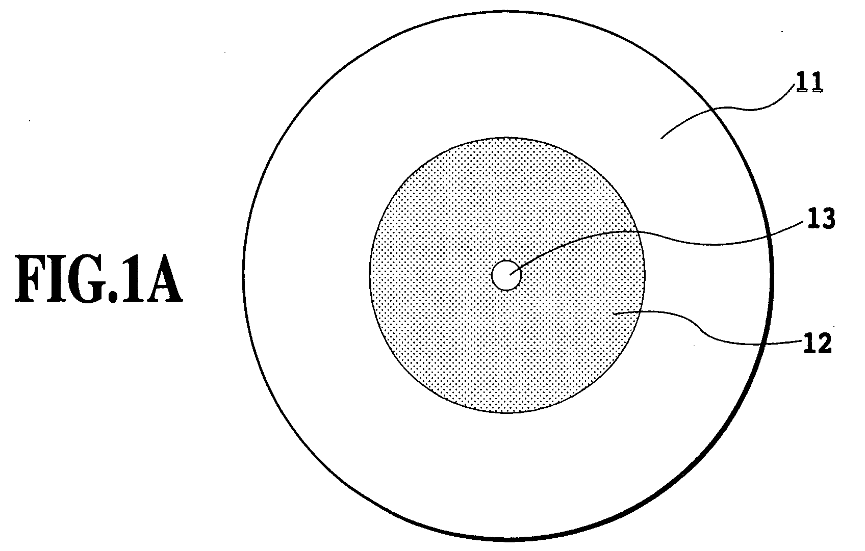
- FIGs. 1A and 1B are views illustrating a single mode photonic crystal fiber in accordance with the present invention: FIG. 1A is a cross-sectional view of the optical fiber; and FIG. 1B is an enlarged view near the core of FIG. 1A.
- the optical fiber which is made of glass or plastics, has a core 11 with a geometric radius ⁇ at the center of a cladding 12 whose outer surface is covered with a fiber material 13.
- the cladding 12 includes many air holes 14 with a diameter d, which are disposed periodically at center-to-center spacings of ⁇ , and extend in the propagation direction of light.
- the core 11 includes no air holes, but is surrounded by the air holes 14 of the cladding 12.
- the single mode optical fiber in accordance with the present invention is designed in such a manner that the center-to-center spacing ⁇ between the air holes is made 1. 5 or more times greater than the wavelength ⁇ of the propagation light, and the V value, which is obtained from the effective refractive index n eff of the cladding 12 and the refractive index n core of the core material by applying the following expression (1), is made greater than 2.4 and less than 3.3.
- V 2 ⁇ ⁇ ( n 2 core - n 2 eff ) 1/2
- the effective refractive index n eff of the cladding at the wavelength of the propagation light is defined as a refractive index when an electromagnetic wave is launched into an infinite plane with the same structure as the cladding, and is obtained by electromagnetic field analysis such as an FDTD method or finite element method.
- the refractive index n core of the core is determined by the core material.
- Such a configuration of the single mode photonic crystal fiber is based on the following idea.
- the optical fiber with the photonic crystal structure it is possible to design its optical characteristics by the arrangement of the air holes.
- the electromagnetic field analysis must be carried out to evaluate its characteristics.
- the inventor of the present invention carried out accurate calculations about the photonic crystal fiber, and found that when the average spacing ⁇ between the centers of the air holes was greater than the wavelength ⁇ of the light used, the photonic crystal fiber could operate in the single mode if the V value was less than 3.3.
- Table 1 summarizes the V values calculated at the wavelength 1.55 ⁇ m, in which numerals in the row designate the values of ⁇ / ⁇ , and numerals in the column designate the values of d/ ⁇ .
- the V values are calculated from the results of obtaining the effective refractive index n eff at the wavelength 1.55 ⁇ m by the electromagnetic field analysis using the FDTD method.
- the italic numerals indicate single mode regions, in which the high-order modes are not confined within the core (that is, they leak out from the core).
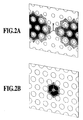
- FIGs. 2A and 2B are cross-sectional views of the optical fiber for illustrating intensity distribution of the high-order mode electromagnetic field in the photonic crystal fiber: FIG. 2A illustrates an example of the intensity distribution of the electromagnetic field of a single mode optical fiber; and FIG. 2B illustrates that of a non-single mode optical fiber.
- the optical fiber has the core at its center with the air holes of the cladding surrounding the core. Darkened regions correspond to regions in which the light is concentrated.
- the analysis uses the V value as an indicator. This is because although the V eff value can be obtained more easily than the V value, the V eff value does not allow to consider the influence of the size of the air holes.
- the arrangement and number of the air holes of the cladding they are not limited to those mentioned above. For example, air holes with different diameters can be placed in the cladding. Furthermore, the geometric radius of the core can be set flexibly and properly.
- the single mode photonic crystal fiber with such a structure can be fabricated by binding a cylindrical glass rod for forming the core and multiple glass pipes for forming the cladding including the air holes. More specifically, a preform, which is formed by binding the cylindrical glass rod and the glass pipes, is heated and drawn so that the clearance between the cylindrical glass rod and the glass pipes, and the clearance between the glass pipes are eliminated during the drawing. As a result, the single mode photonic crystal fiber with the cross section structure as shown in FIG. 1A can be obtained.
- the outer diameter of the photonic crystal fiber is a few tens to a few hundred micrometers, and the diameter of the air holes is about the same order of magnitude as the wavelength.
- the preform which has a similar cross section and the outer diameter of a few to a few tens of centimeters, is formed, followed by drawing to form a fiber as in the fabrication process of an ordinary optical fiber, it is enough to fabricate the preform with a desired cross section, and microprocessing is not required.
- the cross section has a hexagonal close packed structure which offers an advantage of facilitating the production.
- the photonic crystal structure can be implemented by using glass pipes as the circular cylinders which form the cladding, and using a glass rod in place of one or several center glass pipes can form the core, thereby being able to fabricate the pref orm of the optical fiber.
- a method of drilling holes in a lump of glass makes it possible to fabricate an optical fiber preform including air holes with desired arrangement.
- the fabrication method of the preform is not limited to the above.
- a polarization-maintaining optical fiber by releasing the degeneracy of a polarized wave by making the rotational symmetry with respect to the central axis less than three by changing the position and size of part of the air holes.
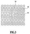
- FIG. 3 is a view illustrating a structure of a polarization-maintaining single mode photonic crystal fiber in accordance with the present invention. It is an enlarged view near the core of the optical fiber when the rotational symmetry with respect to the center of the core is made two by making the diameter of two of the six air holes adjacent to the core different from the diameter of the other air holes.
- the method of destroying the axial symmetry is not limited to the foregoing method. For example, it can be achieved by changing the arrangement of the air holes 23, or by deviating the refractive index distribution of the core 21 or cladding 22 from the axial symmetry.
- the design is made in such a manner that the center-to-center spacing ⁇ between the air holes is 1.5 or more times greater than the wavelength ⁇ of the propagation light, and the V value is greater than 2.4 and less than 3.3, it is possible to provide a single mode photonic crystal fiber having high design flexibility of the optical characteristics and a small bending loss.
Landscapes
- Physics & Mathematics (AREA)
- Optics & Photonics (AREA)
- General Physics & Mathematics (AREA)
- Chemical & Material Sciences (AREA)
- Engineering & Computer Science (AREA)
- Nanotechnology (AREA)
- Life Sciences & Earth Sciences (AREA)
- Biophysics (AREA)
- Crystallography & Structural Chemistry (AREA)
- Optical Fibers, Optical Fiber Cores, And Optical Fiber Bundles (AREA)
Abstract
Description
| 1 | 1.5 | 2 | 3 | 4 | 5 | 6 | |
| 0.9 | 3.084975001 | - | 5.239414873 | - | 6.905900079 | - | 7.493551128 |
| 0.8 | 2.886174789 | 3.808847846 | 4.398182032 | 5.070760951 | 5.436495416 | 5.663553153 | 5.817327725 |
| 0.7 | 2.633456507 | 3.333823439 | 3.74509337 | - | - | - | - |
| 0.6 | 2.36799343 | 2.926547295 | 3.239503162 | 3.571374006 | 3.745593367 | 3.85255735 | 3.925443222 |
| 0.5 | - | 2.568039343 | 2.826403078 | 3.090835754 | 3.225793778 | 3.308923979 | 3.364647526 |
| 0.4 | - | - | - | - | 2.806998399 | 2.87538232 | 2.921618315 |
| 0.3 | 1.507426261 | 1.88738991 | 2.108478301 | 2.330392458 | 2.436070975 | 2.498554896 | 2.539538169 |
| 0.1 | 0.661292571 | - | 1.122272096 | 1.402346686 | 1.562521901 | 1.658943835 | 1.72090935 |
Claims (2)
- A single mode photonic crystal fiber comprising a core with a geometric radius ρ , and a cladding surrounding the core, the cladding including a plurality of cylindrical air holes which extend in a longitudinal direction of the fiber, have a diameter d, and are arranged periodically at center-to-center spacings of Λ, wherein
said core and said cladding are made of glass or plastics, and
a design is made such that the center-to-center spacing Λ between said air holes is made 1.5 or more times greater than a wavelength λ of propagation light, and a normalized frequency V given by the following expression is made greater than 2.4 and less than 3.3: - The single mode photonic crystal fiber as claimed in claim 1, wherein at least one of geometric placement of said air holes in said cladding and optical constant distribution of said cladding or of said core is set in a manner as to make less than three-fold rotational symmetry with respect to a central axis of said core, and the degeneracy of polarization modes of propagation light is removed.
Applications Claiming Priority (3)
| Application Number | Priority Date | Filing Date | Title |
|---|---|---|---|
| JP2002359871A JP3909014B2 (en) | 2002-12-11 | 2002-12-11 | Single mode photonic crystal optical fiber |
| JP2002359871 | 2002-12-11 | ||
| PCT/JP2003/015830 WO2004053545A1 (en) | 2002-12-11 | 2003-12-11 | Single mode photonic crystal optical fiber |
Publications (2)
| Publication Number | Publication Date |
|---|---|
| EP1571470A1 true EP1571470A1 (en) | 2005-09-07 |
| EP1571470A4 EP1571470A4 (en) | 2007-12-26 |
Family
ID=32500963
Family Applications (1)
| Application Number | Title | Priority Date | Filing Date |
|---|---|---|---|
| EP03780715A Ceased EP1571470A4 (en) | 2002-12-11 | 2003-12-11 | OPTICAL FIBER WITH PHOTONIC CRYSTAL MONOMODE |
Country Status (5)
| Country | Link |
|---|---|
| US (1) | US20060024009A1 (en) |
| EP (1) | EP1571470A4 (en) |
| JP (1) | JP3909014B2 (en) |
| AU (1) | AU2003289314A1 (en) |
| WO (1) | WO2004053545A1 (en) |
Cited By (3)
| Publication number | Priority date | Publication date | Assignee | Title |
|---|---|---|---|---|
| GB2457947A (en) * | 2008-02-29 | 2009-09-02 | Sumitomo Electric Industries | All solid photonic band gap fibre |
| US8041170B2 (en) | 2008-02-29 | 2011-10-18 | Sumitomo Electric Industries, Ltd. | Photonic bandgap fiber |
| US8520995B2 (en) | 2009-01-23 | 2013-08-27 | Draka Comteq, B.V. | Single-mode optical fiber |
Families Citing this family (8)
| Publication number | Priority date | Publication date | Assignee | Title |
|---|---|---|---|---|
| JP2006017775A (en) * | 2004-06-30 | 2006-01-19 | Mitsubishi Cable Ind Ltd | Photonic crystal fiber |
| US7301879B1 (en) | 2006-09-12 | 2007-11-27 | Hewlett-Packard Development Company, L.P. | Optical print head |
| JP5478443B2 (en) * | 2010-09-17 | 2014-04-23 | 日本電信電話株式会社 | Number mode fiber |
| CN102436025A (en) * | 2011-12-23 | 2012-05-02 | 中国人民解放军理工大学 | Multi-wavelength Dispersion Compensation Fiber Based on Hybrid Light-guiding Photonic Crystal Fiber |
| CN102854562B (en) * | 2012-10-09 | 2014-03-05 | 天津理工大学 | A high birefringence photonic crystal fiber |
| CN103472527B (en) * | 2013-09-27 | 2015-08-05 | 天津理工大学 | A kind of High-birefringence low-confinement-lossphotonic photonic crystal fiber |
| CN108318966B (en) * | 2018-04-13 | 2019-08-20 | 南京航空航天大学 | A kind of photonic crystal fiber with high birefringence and high brillouin gain |
| CN114035262B (en) * | 2021-11-15 | 2022-07-08 | 北京科技大学 | Rhombic double-core photonic crystal fiber polarization beam splitter with liquid crystal filled in air holes |
Family Cites Families (5)
| Publication number | Priority date | Publication date | Assignee | Title |
|---|---|---|---|---|
| WO2000049436A1 (en) * | 1999-02-19 | 2000-08-24 | Blazephotonics Limited | Improvements in or relating to photonic crystal fibres |
| US6856742B2 (en) | 2000-11-10 | 2005-02-15 | Crystal Fibre A/S | Optical fibres with special bending and dispersion properties |
| JP2002214466A (en) * | 2001-01-23 | 2002-07-31 | Sumitomo Electric Ind Ltd | Optical fiber |
| US6768851B2 (en) * | 2002-03-13 | 2004-07-27 | City University Of Hong Kong | Optical fiber for ultra-high capacity transmission |
| US6917741B2 (en) * | 2002-11-18 | 2005-07-12 | Corning Incorporated | Methods for manufacturing microstructured optical fibers with arbitrary core size |
-
2002
- 2002-12-11 JP JP2002359871A patent/JP3909014B2/en not_active Expired - Lifetime
-
2003
- 2003-11-12 US US10/537,845 patent/US20060024009A1/en not_active Abandoned
- 2003-12-11 AU AU2003289314A patent/AU2003289314A1/en not_active Abandoned
- 2003-12-11 EP EP03780715A patent/EP1571470A4/en not_active Ceased
- 2003-12-11 WO PCT/JP2003/015830 patent/WO2004053545A1/en not_active Ceased
Cited By (5)
| Publication number | Priority date | Publication date | Assignee | Title |
|---|---|---|---|---|
| GB2457947A (en) * | 2008-02-29 | 2009-09-02 | Sumitomo Electric Industries | All solid photonic band gap fibre |
| US8041170B2 (en) | 2008-02-29 | 2011-10-18 | Sumitomo Electric Industries, Ltd. | Photonic bandgap fiber |
| GB2457947B (en) * | 2008-02-29 | 2012-10-17 | Sumitomo Electric Industries | All solid photonic bandgap fibre |
| US8503846B2 (en) | 2008-02-29 | 2013-08-06 | Sumitomo Electric Industries, Ltd. | All solid photonic bandgap fiber |
| US8520995B2 (en) | 2009-01-23 | 2013-08-27 | Draka Comteq, B.V. | Single-mode optical fiber |
Also Published As
| Publication number | Publication date |
|---|---|
| WO2004053545A1 (en) | 2004-06-24 |
| AU2003289314A8 (en) | 2004-06-30 |
| AU2003289314A1 (en) | 2004-06-30 |
| EP1571470A4 (en) | 2007-12-26 |
| JP2006162634A (en) | 2006-06-22 |
| US20060024009A1 (en) | 2006-02-02 |
| JP3909014B2 (en) | 2007-04-25 |
Similar Documents
| Publication | Publication Date | Title |
|---|---|---|
| EP3163339B1 (en) | Multi-core polarization maintaining fiber | |
| US9535217B1 (en) | Multimode fiber combiners | |
| US9703035B2 (en) | Optical connector, method for manufacturing the same, and mold container for manufacturing the same | |
| US9348090B2 (en) | Optical coupling element and manufacturing method | |
| EP3559715B1 (en) | Microstructured fiber optic oscillator and waveguide for fiber scanner | |
| EP0246737A2 (en) | Directional coupler | |
| US20060024009A1 (en) | Single mode photonic crystal optical fiber | |
| EP2071369A1 (en) | Holey fiber | |
| KR100547799B1 (en) | Matrix for photonic crystal fiber and photonic crystal fiber using same | |
| Olyaee et al. | A new design of photonic crystal fiber with ultra-flattened dispersion to simultaneously minimize the dispersion and confinement loss | |
| CN109696724A (en) | A kind of gradual change type photonic crystal polarization maintaining optical fibre | |
| JP6342613B2 (en) | Multi-core optical fiber manufacturing method | |
| CN109254347A (en) | A kind of gradual change type photonic crystal polarization maintaining optical fibre | |
| JPWO2022172910A5 (en) | ||
| US20030136154A1 (en) | Method for manufacturing optical fiber using ultrasonic drill | |
| US6775450B2 (en) | Micro-structured optical fibers | |
| EP1584958A1 (en) | Photonic crystal fiber capable of single-mode transmission and preform thereof | |
| CN209311732U (en) | A kind of gradual change type photonic crystal polarization maintaining optical fibre | |
| WO2013129007A1 (en) | Optical coupling element and method for manufacturing same | |
| Razzak et al. | Optimum design of a dispersion managed photonic crystal fiber for nonlinear optics applications in telecom systems | |
| CN1322344C (en) | Double refraction photo crystal optical fiber | |
| CN107247303A (en) | A kind of new equal aperture pure circle hole high double-refraction photon crystal fiber | |
| JP4194974B2 (en) | Photonic crystal fiber terminal processing method | |
| CN117518340A (en) | Hollow optical fiber and laser beam coupler | |
| KR100751732B1 (en) | A photonic crystal optical fiber having holes of different sizes for each cladding region |
Legal Events
| Date | Code | Title | Description |
|---|---|---|---|
| PUAI | Public reference made under article 153(3) epc to a published international application that has entered the european phase |
Free format text: ORIGINAL CODE: 0009012 |
|
| 17P | Request for examination filed |
Effective date: 20050609 |
|
| AK | Designated contracting states |
Kind code of ref document: A1 Designated state(s): AT BE BG CH CY CZ DE DK EE ES FI FR GB GR HU IE IT LI LU MC NL PT RO SE SI SK TR |
|
| AX | Request for extension of the european patent |
Extension state: AL LT LV MK |
|
| DAX | Request for extension of the european patent (deleted) | ||
| RBV | Designated contracting states (corrected) |
Designated state(s): DE FR GB |
|
| RIN1 | Information on inventor provided before grant (corrected) |
Inventor name: FUJITA, MORIYUKINERIMA OFF:OF MITSUBISHI CABLE Inventor name: TANAKA, MASATOSHIAMAGASAKI WORKS OF MITSUBISHI CA Inventor name: SUZUKI, AKIHITON Inventor name: SUZUKI, KAZUNORINTT INTELLECTUAL PROPERTY CENTER Inventor name: KAWANISHI, SATOKINTT INTELLECTUAL PROPERTY CENTER Inventor name: KUBOTA, HIROKAZUNTT INTELLECTUAL PROPERTY CENTER |
|
| A4 | Supplementary search report drawn up and despatched |
Effective date: 20071122 |
|
| RIC1 | Information provided on ipc code assigned before grant |
Ipc: G02B 6/02 20060101AFI20071117BHEP |
|
| 17Q | First examination report despatched |
Effective date: 20081126 |
|
| REG | Reference to a national code |
Ref country code: DE Ref legal event code: R003 |
|
| STAA | Information on the status of an ep patent application or granted ep patent |
Free format text: STATUS: THE APPLICATION HAS BEEN REFUSED |
|
| 18R | Application refused |
Effective date: 20111206 |