EP1571461B1 - A method for improving the precision of localization estimates - Google Patents
A method for improving the precision of localization estimates Download PDFInfo
- Publication number
- EP1571461B1 EP1571461B1 EP05101113.8A EP05101113A EP1571461B1 EP 1571461 B1 EP1571461 B1 EP 1571461B1 EP 05101113 A EP05101113 A EP 05101113A EP 1571461 B1 EP1571461 B1 EP 1571461B1
- Authority
- EP
- European Patent Office
- Prior art keywords
- localization
- estimates
- objects
- initial
- post
- Prior art date
- Legal status (The legal status is an assumption and is not a legal conclusion. Google has not performed a legal analysis and makes no representation as to the accuracy of the status listed.)
- Not-in-force
Links
- 230000004807 localization Effects 0.000 title claims description 231
- 238000000034 method Methods 0.000 title claims description 90
- 230000033001 locomotion Effects 0.000 claims description 23
- 238000005259 measurement Methods 0.000 description 71
- 238000012805 post-processing Methods 0.000 description 47
- 238000003491 array Methods 0.000 description 16
- 238000012545 processing Methods 0.000 description 16
- 230000008569 process Effects 0.000 description 13
- 230000006870 function Effects 0.000 description 10
- 238000004891 communication Methods 0.000 description 7
- 238000010586 diagram Methods 0.000 description 7
- 230000004044 response Effects 0.000 description 6
- 238000012935 Averaging Methods 0.000 description 5
- 230000001419 dependent effect Effects 0.000 description 5
- 230000008030 elimination Effects 0.000 description 5
- 238000003379 elimination reaction Methods 0.000 description 5
- 230000003287 optical effect Effects 0.000 description 5
- 230000007423 decrease Effects 0.000 description 4
- 230000002093 peripheral effect Effects 0.000 description 4
- 238000007781 pre-processing Methods 0.000 description 4
- 230000008901 benefit Effects 0.000 description 3
- 238000007796 conventional method Methods 0.000 description 3
- 238000001914 filtration Methods 0.000 description 3
- 230000005055 memory storage Effects 0.000 description 3
- 230000006855 networking Effects 0.000 description 3
- 230000009467 reduction Effects 0.000 description 3
- 230000005236 sound signal Effects 0.000 description 3
- 238000007619 statistical method Methods 0.000 description 3
- 230000003044 adaptive effect Effects 0.000 description 2
- 238000004364 calculation method Methods 0.000 description 2
- 238000005516 engineering process Methods 0.000 description 2
- 230000035484 reaction time Effects 0.000 description 2
- 239000007787 solid Substances 0.000 description 2
- CDFKCKUONRRKJD-UHFFFAOYSA-N 1-(3-chlorophenoxy)-3-[2-[[3-(3-chlorophenoxy)-2-hydroxypropyl]amino]ethylamino]propan-2-ol;methanesulfonic acid Chemical compound CS(O)(=O)=O.CS(O)(=O)=O.C=1C=CC(Cl)=CC=1OCC(O)CNCCNCC(O)COC1=CC=CC(Cl)=C1 CDFKCKUONRRKJD-UHFFFAOYSA-N 0.000 description 1
- 238000003324 Six Sigma (6σ) Methods 0.000 description 1
- 238000004458 analytical method Methods 0.000 description 1
- 238000013459 approach Methods 0.000 description 1
- 230000015572 biosynthetic process Effects 0.000 description 1
- 238000004422 calculation algorithm Methods 0.000 description 1
- 230000006835 compression Effects 0.000 description 1
- 238000007906 compression Methods 0.000 description 1
- 230000003247 decreasing effect Effects 0.000 description 1
- 238000009826 distribution Methods 0.000 description 1
- 238000005315 distribution function Methods 0.000 description 1
- 230000007246 mechanism Effects 0.000 description 1
- 238000012986 modification Methods 0.000 description 1
- 230000004048 modification Effects 0.000 description 1
- 230000001151 other effect Effects 0.000 description 1
- 238000004806 packaging method and process Methods 0.000 description 1
- 239000002245 particle Substances 0.000 description 1
- 230000001629 suppression Effects 0.000 description 1
- 238000012546 transfer Methods 0.000 description 1
- 230000007723 transport mechanism Effects 0.000 description 1
Images


Classifications
-
- G—PHYSICS
- G01—MEASURING; TESTING
- G01S—RADIO DIRECTION-FINDING; RADIO NAVIGATION; DETERMINING DISTANCE OR VELOCITY BY USE OF RADIO WAVES; LOCATING OR PRESENCE-DETECTING BY USE OF THE REFLECTION OR RERADIATION OF RADIO WAVES; ANALOGOUS ARRANGEMENTS USING OTHER WAVES
- G01S7/00—Details of systems according to groups G01S13/00, G01S15/00, G01S17/00
-
- H—ELECTRICITY
- H04—ELECTRIC COMMUNICATION TECHNIQUE
- H04W—WIRELESS COMMUNICATION NETWORKS
- H04W4/00—Services specially adapted for wireless communication networks; Facilities therefor
- H04W4/02—Services making use of location information
-
- H—ELECTRICITY
- H04—ELECTRIC COMMUNICATION TECHNIQUE
- H04W—WIRELESS COMMUNICATION NETWORKS
- H04W4/00—Services specially adapted for wireless communication networks; Facilities therefor
- H04W4/02—Services making use of location information
- H04W4/029—Location-based management or tracking services
-
- H—ELECTRICITY
- H04—ELECTRIC COMMUNICATION TECHNIQUE
- H04W—WIRELESS COMMUNICATION NETWORKS
- H04W8/00—Network data management
- H04W8/02—Processing of mobility data, e.g. registration information at HLR [Home Location Register] or VLR [Visitor Location Register]; Transfer of mobility data, e.g. between HLR, VLR or external networks
- H04W8/08—Mobility data transfer
Definitions
- the invention is related to object localization and tracking within a prescribed search area, and in particular, to a system and process for improving the precision of localization estimates generated by use of a receiving array, such as, for example, microphone arrays, directional antenna arrays, radar receiver arrays, etc., by providing duster-based statistical post-processing of initial localization measurements or estimates.
- a receiving array such as, for example, microphone arrays, directional antenna arrays, radar receiver arrays, etc.
- Localization and tracking of objects within prescribed regions is an important element of many systems.
- a number of conventional audio conferencing applications use microphone arrays with conventional sound source localization (SSL) processing (i.e., time-delay estimates, beamsteering, etc.) to enable the speech or sound of particular individuals to be effectively isolated and processed as desired.
- SSL sound source localization
- Similar techniques have used arrays of directional antennas for locating radio sources for a number of applications, such as, for example, for determining which node or nodes are to be used by particular subscribers within in a wireless computer network.
- Still other similar techniques have been used for tracking objects using radar or laser receiver arrays. In general, such techniques are well known to those skilled in the art.
- conventional microphone arrays typically include an arrangement of microphones in some predetermined layout. These microphones are generally used to capture sound waves from various directions and originating from different points in space.
- One of a number of conventional techniques is then used to perform SSL.
- these SSL techniques fall into two categories, including those based on time delay estimates (TDE), and those based on beamsteering. Finding the direction to a sound source plays an important role in spatial filtering, i.e. pointing a beam to the sound source and suppressing any noises coming from other directions.
- the direction to the sound source is used for speaker tracking and post-processing of recorded audio signals.
- speaker tracking is often used for dynamically directing a video camera toward the person speaking.
- most sound source localization systems process the signals from a microphone array by first preprocessing each signal from each microphone of the array. This preprocessing typically includes packaging the signal in frames, performing noise suppression, and classifying individual frames for determining whether particular frames will be processed or rejected for the purposes of determining the location of the sound source.
- the actual sound source localization typically involves the use of conventional SSL techniques including, for example, TDE or beamsteering techniques, to provide either initial direction estimates or a probability distribution function (PDF) for indicating where a sound source is located.
- This location can be defined in terms of one-dimensional localization (i.e., the angle along which the sound source is located in a plane), two-dimensional localization (i.e., two angles, direction and elevation, for defining a vector representing the direction of the sound source in a three dimensional space), and full three-dimensional localization (i.e., direction, elevation and distance, for locating a point in a three-dimensional space at which the sound source is located).
- SSL technique the goal is typically to provide robustness to reverberation, the ability to distinguish multiple sound sources, and high location precision in potentially noisy environments.
- a post-processing phase is often implemented.
- this post-processing combines the results of several localization measurements to increase the precision, to follow the sound source movements, or to track multiple sound sources.
- Various conventional techniques used for SSL post-processing include simple averaging, statistical processing, Kalman filtering, particle filtering, etc. Such techniques are typically application dependent, but are generally directed at removing localizations from reverberated waves and strong reflections, and to improve sound source localization precision.
- any further processing of the audio signal is enhanced.
- Signal source or object localization with respect to other signal types is often accomplished using pre-and post-processing techniques similar to those described above for the case of sound waves captured via a microphone array.
- such localization techniques often include beamsteering techniques adapted for different signal and receiver array types (e.g., directional antenna arrays, radar or laser receiver arrays, etc.).
- beamsteering techniques adapted for different signal and receiver array types (e.g., directional antenna arrays, radar or laser receiver arrays, etc.).
- localization of other signal types is typically based on analysis of the propagation of signals (e.g., sound waves, radio waves, radar wave reflections, etc.).
- one primary goal is to provide fast and precise localization estimates or measurements, even in the presence of noise and other effects, such as diffraction, interference, reflection, etc., which tend to decrease localization precision and reliability.
- post-processing of localization estimates is generally designed to increase the precision of localization estimates. Therefore, what is needed is a system and process for providing fast and reliable post-processing of localization data for improving the precision of localization estimates. Further, such a system and method should be operable with and adaptable for existing localization techniques.
- a system and method as described herein operates to enhance existing signal localization techniques for tracking or locating one or more objects or signal sources by improving reliability and precision of initial localization estimates derived from conventional localization techniques.
- object will be used to refer either to actual objects being tracked or located via localization methods, or to signal sources (such as sound from a person talking).
- Conventional localization techniques that are improved through use of the post-processing techniques include, for example, conventional sound source localization (SSL) systems based on microphone array inputs, conventional radio source location systems based on directional antenna array inputs, conventional target location and tracking systems based on radar or laser receiver arrays, etc. Note that such localization techniques are well known to those skilled in the art, and will not be described in detail herein.
- the post-processing system and method described herein applies statistical real-time clustering process to initial localization estimates, and then uses this real-time clustering to generate new localization estimates having improved precision and reliability relative to the initial localization estimates.
- the post-processing techniques described herein are adaptable for use with conventional systems that provide signal source localization estimates.
- the system and method described herein has also been observed to provide improved precision and reliability where initial object localization estimates are gathered in environments which may include noise, reflections, reverberations, or other interference.
- the process described herein begins by collecting, generating, or otherwise acquiring initial object localization estimates or measurements using any of a number of conventional localization techniques.
- conventional localization data is typically provided in one, two, or three dimensions (e.g., direction; direction and angle; or direction, angle and distance) as a function of time.
- the post-processing techniques described herein may be generalized to localization data of any dimensionality, for purposes of explanation the following discussion will assume that the localization data is three-dimensional, i.e., direction, elevation and distance within a prescribed region, along with known or computed standard deviations for direction, elevation and distance, ⁇ ⁇ , ⁇ ⁇ , and ⁇ ⁇ , respectively.
- the post-processing system described herein takes an input of conventional localization estimates, with each localization estimate comprising: 1) positional data; 2) estimated positional reliability; and 3) a data time stamp. This data is then used to derive new localization estimates having improved reliability relative to the input localization estimates.
- This set of information (i.e., position, reliability, and time) for each initial localization estimate will be referred to throughout this description as “initial localization estimates,” or simply as “initial measurements.”
- the post-processing system and method described herein begins by first discarding all localization measurements older than a predetermined time.
- This predetermined time, or measurement "lifetime” is the time during which any particular localization estimate will be considered valid, and therefore, during which the localization estimate will be used for post-processing computations.
- This 'lifetime is simply a measure of the time since a particular localization estimate was generated (i.e., the time between the time stamp of the particular localization estimate and the current time).
- an adaptive lifetime is computed based on computed object motions, with the lifetime being chosen as a tradeoff between response time and position validity as a function of time.
- the computed motions are simply computed using position estimates as a function of time.
- the post-processing then continues with a multi-stage process, including: 1) "clustering" the initial localization estimates (those within the predetermined life-time) in spatially spread overlapping sections; 2) identifying "potential objects” within the clusters; 3) estimating the position and standard deviation of the potential objects based on the clustering; and 4) eliminating likely duplicate objects.
- the post-processing further continues by computing a confidence level for the position estimate for each object (after elimination of duplicate objects). Consequently, the final result of the post-processing system and method described herein is a list of objects, each presented with location, standard deviation, and in one embodiment, the confidence level of the object location.
- Figure 1 illustrates an example of a suitable computing system environment 100 with which the invention may be implemented.
- the computing system environment 100 is only one example of a suitable computing environment and is not intended to suggest any limitation as to the scope of use or functionality of the invention. Neither should the computing environment 100 be interpreted as having any dependency or requirement relating to any one or combination of components illustrated in the exemplary operating environment 100.
- the invention is operational with numerous other general purpose or special purpose computing system environments or configurations.
- Examples of well known computing systems, environments, and/or configurations that may be suitable for use with the invention include, but are not limited to, personal computers, server computers, hand-held, laptop or mobile computer or communications devices such as cell phones and PDA's, multiprocessor systems, microprocessor-based systems, set top boxes, programmable consumer electronics, network PCs, minicomputers, mainframe computers, distributed computing environments that include any of the above systems or devices, and the like.
- the invention may be described in the general context of computer-executable instructions, such as program modules, being executed by a computer in combination with hardware modules, including components of a microphone array 198, or other receiver array (not shown), such as, for example, a directional radio antenna array, a radar receiver array, etc.
- program modules include routines, programs, objects, components, data structures, etc., that perform particular tasks or implement particular abstract data types.
- the invention may also be practiced in distributed computing environments where tasks are performed by remote processing devices that are linked through a communications network.
- program modules may be located in both local and remote computer storage media including memory storage devices.
- an exemplary system for implementing the invention includes a general-purpose computing device in the form of a computer 110.
- Components of computer 110 may include, but are not limited to, a processing unit 120, a system memory 130, and a system bus 121 that couples various system components including the system memory to the processing unit 120.
- the system bus 121 may be any of several types of bus structures including a memory bus or memory controller, a peripheral bus, and a local bus using any of a variety of bus architectures.
- bus architectures include Industry Standard Architecture (ISA) bus, Micro Channel Architecture (MCA) bus, Enhanced ISA (EISA) bus, Video Electronics Standards Association (VESA) local bus, and Peripheral Component Interconnect (PCI) bus also known as Mezzanine bus.
- Computer 110 typically includes a variety of computer readable media.
- Computer readable media can be any available media that can be accessed by computer 110 and includes both volatile and nonvolatile media, removable and non-removable media.
- Computer readable media may comprise computer storage media and communication media.
- Computer storage media includes volatile and nonvolatile removable and non-removable media implemented in any method or technology for storage of information such as computer readable instructions, data structures, program modules, or other data.
- Computer storage media includes, but is not limited to, RAM, ROM, PROM, EPROM, EEPROM, flash memory, or other memory technology; CD-ROM, digital versatile disks (DVD), or other optical disk storage; magnetic cassettes, magnetic tape, magnetic disk storage, or other magnetic storage devices; or any other medium which can be used to store the desired information and which can be accessed by computer 110.
- Communication media typically embodies computer readable instructions, data structures, program modules or other data in a modulated data signal such as a carrier wave or other transport mechanism and includes any information delivery media.
- modulated data signal means a signal that has one or more of its characteristics set or changed in such a manner as to encode information in the signal.
- communication media includes wired media such as a wired network or direct-wired connection, and wireless media such as acoustic, RF, infrared, and other wireless media. Combinations of any of the above should also be included within the scope of computer readable media.
- the system memory 130 includes computer storage media in the form of volatile and/or nonvolatile memory such as read only memory (ROM) 131 and random access memory (RAM) 132.
- ROM read only memory
- RAM random access memory
- BIOS basic input/output system
- RAM 132 typically contains data and/or program modules that are immediately accessible to and/or presently being operated on by processing unit 120.
- Figure 1 illustrates operating system 134, application programs 135, other program modules 136, and program data 137.
- the computer 110 may also include other removable/non-removable, volatile/nonvolatile computer storage media.
- Figure 1 illustrates a hard disk drive 141 that reads from or writes to non-removable, nonvolatile magnetic media, a magnetic disk drive 151 that reads from or writes to a removable, nonvolatile magnetic disk 152, and an optical disk drive 155 that reads from or writes to a removable, nonvolatile optical disk 156 such as a CD ROM or other optical media.
- removable/non-removable, volatile/nonvolatile computer storage media that can be used in the exemplary operating environment include, but are not limited to, magnetic tape cassettes, flash memory cards, digital versatile disks, digital video tape, solid state RAM, solid state ROM, and the like.
- the hard disk drive 141 is typically connected to the system bus 121 through a non-removable memory interface such as interface 140, and magnetic disk drive 151 and optical disk drive 155 are typically connected to the system bus 121 by a removable memory interface, such as interface 150.
- hard disk drive 141 is illustrated as storing operating system 144, application programs 145, other program modules 146, and program data 147. Note that these components can either be the same as or different from operating system 134, application programs 135, other program modules 136, and program data 137. Operating system 144, application programs 145, other program modules 146, and program data 147 are given different numbers here to illustrate that, at a minimum, they are different copies.
- a user may enter commands and information into the computer 110 through input devices such as a keyboard 162 and pointing device 161, commonly referred to as a mouse, trackball, or touch pad.
- Other input devices may include a joystick, game pad, satellite dish, scanner, radio receiver, and a television or broadcast video receiver, or the like. Still further input devices (not shown) may include receiving arrays or signal input devices, such as, for example, a directional radio antenna array, a radar receiver array, etc. These and other input devices are often connected to the processing unit 120 through a wired or wireless user input interface 160 that is coupled to the system bus 121, but may be connected by other conventional interface and bus structures, such as, for example, a parallel port, a game port, a universal serial bus (USB), an IEEE 1394 interface, a BluetoothTM wireless interface, an IEEE 802.11 wireless interface, etc.
- USB universal serial bus
- the computer 119 may also include a speech or audio input device, such as a microphone or a microphone array 198, as well as a loudspeaker 197 or other sound output device connected via an audio interface 199, again including conventional wired or wireless interfaces, such as, for example, parallel, serial, USB, IEEE 1394, BluetoothTM, etc.
- a speech or audio input device such as a microphone or a microphone array 198
- a loudspeaker 197 or other sound output device connected via an audio interface 199, again including conventional wired or wireless interfaces, such as, for example, parallel, serial, USB, IEEE 1394, BluetoothTM, etc.
- a monitor 191 or other type of display device is also connected to the system bus 121 via an interface, such as a video interface 190.
- computers may also include other peripheral output devices such as a printer 196, which may be connected through an output peripheral interface 195.
- the computer 110 may operate in a networked environment using logical connections to one or more remote computers, such as a remote computer 180.
- the remote computer 180 may be a personal computer, a server, a router, a network PC, a peer device, or other common network node, and typically includes many or all of the elements described above relative to the computer 110, although only a memory storage device 181 has been illustrated in Figure 1 .
- the logical connections depicted in Figure 1 include a local area network (LAN) 171 and a wide area network (WAN) 173, but may also include other networks.
- LAN local area network
- WAN wide area network
- Such networking environments are commonplace in offices, enterprise-wide computer networks, intranets, and the internet.
- the computer 110 When used in a LAN networking environment, the computer 110 is connected to the LAN 171 through a network interface or adapter 170. When used in a WAN networking environment, the computer 110 typically includes a modem 172 or other means for establishing communications over the WAN 173, such as the Internet.
- the modem 172 which may be internal or external, may be connected to the system bus 121 via the user input interface 160, or other appropriate mechanism.
- program modules depicted relative to the computer 110, or portions thereof may be stored in the remote memory storage device.
- Figure 1 illustrates remote application programs 185 as residing on memory device 181. It will be appreciated that the network connections shown are exemplary and other means of establishing a communications link between the computers may be used.
- a system and method as described herein operates to enhance existing signal localization techniques for tracking or locating one or more objects or signal sources by improving reliability and precision of initial localization estimates derived from conventional localization techniques.
- object will be used to refer either to actual objects being tracked or located via localization methods, or to signal sources (such as sound from a person talking, radio sources, radar reflections, etc.).
- Localization techniques that are improved through use of the post-processing techniques include, for example, conventional sound source localization (SSL) systems based on microphone array inputs, conventional radio source location systems based on directional antenna array inputs, conventional target location and tracking systems based on radar or laser receiver arrays, etc. Note that such localization techniques are well known to those skilled in the art, and will not be described in detail herein.
- the post-processing system and method described herein applies statistical real-time clustering process to initial localization estimates, and then uses this real-time clustering to generate new localization estimates having improved precision and reliability relative to the initial localization estimates.
- the post-processing techniques described herein are adaptable for use with conventional systems that provide signal source localization estimates.
- the system and method described herein has also been observed to provide improved precision and reliability where initial object localization estimates are gathered in environments which may include noise, reflections, reverberations, or other interference.
- the system and method described herein for post-processing of localization estimates begins by collecting, generating, or otherwise acquiring initial object localization estimates or measurements using any of a number of conventional localization techniques.
- conventional localization data is typically provided in one, two, or three dimensions (e.g., direction; direction and angle; or direction, angle and distance) as a function of time.
- the post-processing techniques described herein may be generalized to localization data of any dimensionality, for purposes of explanation the following discussion will assume that the localization data is three-dimensional, i.e., direction, elevation and distance within a prescribed region, along with known or computed standard deviations for direction, elevation and distance, ⁇ ⁇ , ⁇ ⁇ and ⁇ ⁇ , respectively.
- the post-processing system described herein takes an input of conventional localization estimates, with each localization estimate comprising: 1) positional data; 2) estimated positional reliability; and 3) a data time stamp. This data is then used to derive new localization estimates having improved reliability relative to the input localization estimates.
- This set of information (i.e., position, reliability, and time) for each initial localization estimate will be referred to throughout this description as “initial localization estimates,” or simply as “initial measurements.”
- the post-processing system and method described herein begins by first discarding all localization measurements older than a predetermined time.
- This predetermined time, or measurement "lifetime” is the time during which any particular localization estimate will be considered valid, and therefore, during which the localization estimate will be used for post-processing computations.
- This "lifetime” is simply a measure of the time since a particular localization estimate was generated (i.e., the time between the time stamp of the particular localization estimate and the current time).
- an adaptive lifetime is computed based on computed object motions, with the lifetime being chosen as a tradeoff between response time and position validity as a function of time.
- the computed motions are simply computed using position estimates as a function of time.
- the post-processing then continues with a multi-stage process, including: 1) "clustering" the initial localization estimates (those within the predetermined life-time) in spatially spread overlapping sections; 2) identifying "potential objects” within the clusters; 3) estimating the position and standard deviation of the potential objects based on the clustering; and 4) eliminating likely duplicate objects.
- the post-processing further continues by computing a confidence level for the position estimate for each object (after elimination of duplicate objects). Consequently, the final result of the post-processing system and method described herein is a list of objects, each presented with location, standard deviation, and in one embodiment, the confidence level of the object location.
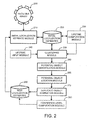
- FIG. 2 illustrates the processes summarized above.
- the system diagram of FIG. 2 illustrates the interrelationships between program modules for implementing a system and method for post-processing of initial localization estimates for improving the precision and reliability of those localization estimates.
- This system and method will generally be referred to below as a "post-processor.”
- any boxes and interconnections between boxes that are represented by broken or dashed lines in FIG. 2 represent alternate embodiments of the post-processor described herein, and that any or all of these alternate embodiments, as described below, may be used in combination with other alternate embodiments that are described throughout this document.
- the post-processor operates to improve initial localization estimates 220 derived from a conventional receiver array 200 and a conventional initial localization estimate module 210.
- the receiver array 200 is any conventional receiving array, such as, for example, a microphone array, a directional antenna array, a radar array, a laser receiver array, etc.
- the receiver array 200 may also be a single receiver which acts in a manner similar to an array of receivers.
- a single rotating receiver such as a rotating radar receiver, will acquire signals from various directions about the axis of rotation.
- the radar receiver acts in a manner similar to a radar array by receiving signals from various directions as it rotates.
- localization estimates from such receivers are compatible with the post-processor described herein, it should be noted that single receiver systems (as opposed to actual arrays) tend to have longer response times for providing localization estimates.
- the initial localization estimate module 210 is a conventional localization or tracking system for providing localization estimates from signals or inputs received from the receiver array 200.
- the initial localization estimate module 210 is a conventional sound source localization (SSL) system.
- SSL sound source localization
- the post-processor is operable with any of a number of conventional localization systems, and is not limited to merely improving the precision and reliability of localization estimates provided by a conventional microphone array/SSL system.
- the post-processor uses a clustering module 250 for real-time clustering of the initial localization estimates 220 in spatially spread overlapping sections. Note that this real-time clustering process with spatially spread overlapping sections is described in detail below in Section 3.2.1. As noted above, in one embodiment, only those estimates whose lifetimes have not yet expired are processed via the real-time clustering process. Localization estimates whose lifetimes have expired are simply discarded with respect to the post-processing described herein.
- a lifetime computation module 230 automatically computes optimized localization estimate lifetimes based on computed object motions. For example, because the initial localization estimates 220 include a time stamp indicating the time each localization estimate was generated, it is a simple matter to compute approximate object motions as a function of time. Given these object motions, the lifetime computation module 230 then determines an appropriate lifetime for localization estimates for each object. As noted above, these lifetimes are dependent upon the motion of particular objects. However, the lifetimes are also dependent upon the type of receiver array 200 and localization system being used.
- the lifetime computation module 230 then automatically adjusts the localization estimate lifetimes up or down by some small amount to account for computed object motions, with the goal being to provide a lifetime that ensures that the localization estimates are not so old as to be relatively unreliable. Further, in the case of multiple objects, each object may then have a different localization estimate lifetime, dependant upon the motion of each particular object.
- a lifetime input module 240 is used to provide a constant lifetime to be used for all initial localization estimates 220. Again, the length of the lifetime should be dependent upon the type of receiver array 200, the type of localization system being used, and expected object motions.
- a potential object identification module 260 identifies clusters of localization estimates representing potential objects within each spatially spread overlapping section through a statistical analysis of the localization estimate clusters.
- potential objects are identified in these overlapping sections by using a threshold for identifying those sections which contain one or more objects. As described in detail below in Section 3.2.2, if a computed average weight of any section with a non zero number of measurements exceeds a predetermined threshold, than it is assumed that there is a potential object in that section, and it is selected for further processing.
- a potential object localization module 265 then computes a position for each potential object from the localization estimates comprising each cluster. At this point, the position of potential objects represents a refinement of the initial localization estimates 220. However, as a result of using overlapping sections, particular localization estimates or measurements may exist in two or more neighboring sections. Note that the computation of potential object positions is described in further detail below in Section 3.2.3.
- the next step uses a duplicate object elimination module 270 to eliminate duplications of identified objects resulting from the use of overlapping sections.
- a duplicate object elimination module 270 to eliminate duplications of identified objects resulting from the use of overlapping sections.
- the object identification module has analyzed the clusters of localization estimates, there is a list of hypothetical or potential objects, each represented by position, standard deviation and weight. However, because of the use of overlapping sections, there are often duplications in this list, hence the use of the term "potential objects.”
- duplications are deemed to exist if the distance between any two hypothetical objects is less than a threshold distance. Where duplicates are deemed to exist, the duplicate object elimination module simply removes the potential object having a lower weight from the list. In the unlikely case of equal weights, one of the potential objects is simply randomly eliminated. Any remaining potential objects are then simply provided as the new localization estimates 280.
- a confidence level computation module 290 then computes a confidence level or measure for each of the new localization estimates 280. Computation of this confidence level is described below in further detail in Section 3.2.5.
- the new localization estimates are provided back to the initial localization estimate module 210 for use in generating new initial localization estimates 220.
- the use of existing localization estimates for initializing localization computations is well known to those skilled in the art, and will not be described in detail herein.
- the post-processor described herein is applicable to many different localization techniques.
- the post processing system and method described herein operates to improve sound source localization (SSL) results in audio systems using microphone arrays.
- the post processing system and method described herein also operates to improve localization of radio signals, such as, for example, to select particular directional antennas in an antenna array for use with computer endpoints in a wireless computer network.
- radio signals such as, for example, to select particular directional antennas in an antenna array for use with computer endpoints in a wireless computer network.
- Other examples include radar and laser tracking systems. All such systems will be referred to collectively below as a "source localizer.”
- each localization measurement includes: 1) an object location, represented by direction, elevation and distance; 2) a weight which provides an indication of how much the source localizer trusts this measurement; and 3) a time stamp which indicates the time of each localization measurement.
- the actual algorithm used by the localizer for generating the initial localization estimates doesn't really mater, as long as it provides the information noted above (i.e., object location, weight, and time).
- the initial localization estimates are collected by a post-processor input queue.
- the post-processor then removes all measurements from the input queue that are older than a given lifetime T.
- this lifetime is either automatically computed based on object motions, or predefined for particular localization systems. In general, using a larger lifetime means that more results are available for processing, thereby facilitating a more reliable distinction between real objects and reflections, and providing for better precision.
- longer lifetimes result in larger response times when the object or signal source moves or changes position.
- Post-processing of the initial localization estimates involves a number of stages, including: clustering, finding potential objects (i.e., sound sources, radio sources, etc.), estimating positions of the potential objects, reduction or elimination of duplicate objects, and calculation of the confidence levels. These post-processing stages are described in the following Sections.
- the work volume i.e., the space or volume being monitored or served by the receiving array
- the work volume is pre-defined or can be readily determined using conventional techniques.
- the following parameters are known with respect to the work volume:
- the work volume is automatically divided into a number, M , of overlapping regions or sections. Note that using regions of equal size is not necessary, but it serves to reduce computational complexity. Note that the section size depends on the precision of the initial estimator and shouldn't typically be larger than about four to six times the standard deviation, e.g., 6 ⁇ .
- the number of overlapping regions or sections and amount of overlap is user definable. Any number or size of regions may be used. However, using more regions with smaller sizes tends to increase the precision of localization estimates, at the cost of increased computational overhead.
- the region size is the resolution of the post-processor to detect separate objects, assuming one object per cluster. The minimal size, however, depends on the precision of the initial estimator, where it is desired to have almost all measurements from one object to go to the same cluster. Therefore, for standard distributions this means that a region size of approximately 6 times the standard deviation (e.g., 6 ⁇ ) will capture about 99% of the measurements for the object. However, for particular purposes, the cluster or region size can be larger than 6 ⁇ .
- the 6's in the denominator of Equation (1) represent the use of region sizes of six times the standard deviation of the initial estimator. As noted above, other region sizes may be used to provide for the desired accuracy. However, it should be noted that a 6-sigma interval (e.g., ⁇ 3-sigma around the average) holds approximately 99% of the measurements.
- each initial localization estimate is then simply assigned to whatever regions of the work volume cover each initial localization estimate. Because each initialization estimate has an associated lifetime, multiple localization estimates are typically available for each object. Consequently, assigning localization estimates to particular regions results in the formation of localization estimate clusters within each region. Note that due to the use of overlapping regions, particular measurement may be assigned to two or more neighboring sections, depending upon the amount of overlap. As noted above, the use of larger regions of overlap results in better resolution for separate objects but increases the necessary computations.
- determination of whether particular regions include one or more potential objects is accomplished using a weight-based threshold.
- identifying those sections with potential objects was accomplished by first computing an average weight, W th , of all sections with a non-zero number of measurements (i.e., at least one localization estimate was assigned to that particular region), which represents the weight-based threshold.
- W th represents the threshold weight used to gauge each region of the work volume. Note that the threshold weight is computed using the original weights provided as part of the initial localization estimates.
- K depends on the number of the sections and the number of false measurements (i.e., measurements in sections resulting from reflections and noise rather than real objects).
- sections with false measurements typically contain about one to two measurements, as a result of reflections and noise.
- K is application dependent, and for particular implementations of the post-processor, it may be desirable to avoid processing of sections with less than three measurements (or some other minimal number), depending on how many measurements are provided by the initial estimator as a function of time.
- position estimates can be computed for potential objects in all of the regions of the work volume, it is unlikely that there are actually any objects, or any localization estimates having high reliability, in regions that were not flagged in the previous step as having a weight exceeding the threshold, W th . Consequently, in one embodiment, position estimates are only computed for potential objects within those regions having a weight which exceeds the threshold, W th .
- the position estimation provided during this stage of the post-processing involves a two-stage statistical processing approach.
- the first stage computes a weighted averaging of all measurements in the section.
- a second pass of weighted averaging is performed for measurements within a particular distance of the computed object position, p i .
- a weighted averaging of measurements in the range of p i ⁇ 2 ⁇ i was used to obtain a final position estimate p ⁇ i for each section.
- the number of measurements in the range of p i ⁇ 2 ⁇ i is denoted as ⁇ i .
- the criterion for determining whether any two objects are duplicates is based on a computed distance between any two or more hypothetical or potential objects. For example, if the distance between any two hypothetical objects k and l, where ( k#l ), in all directions is less than the amount of section overlap in each direction, then these two objects are considered as actually representing the same object or signal source.
- the post-processing continues by computing confidence levels for each object position estimate generated during the post-processing stages described above.
- confidence levels are provided as a number in a range of 0 to 1, with 0 representing no confidence, and 1 representing full confidence.
- the factors affecting the computed confidence levels are the number of measurements ⁇ i , , the standard deviation ⁇ i and the latest time stamp among these ⁇ i , measurements.
- N crit when the number of measurements is less than a given number, N crit , the confidence level decreases, thereby indicating less trustworthy position measurements.
- position measurements having larger standard deviations are also typically less trustworthy.
- position estimates having larger standard deviations are also typically less trustworthy.
- the confidence level was decreased for objects as the age of the most recent measurement approached the measurement lifetime (see Sections 2.1 and 2.2 for a discussion of measurement lifetimes).
- c iN n ⁇ i / N crit
- c iN is the confidence level based on the number of measurements
- c i ⁇ , c i ⁇ and c i ⁇ are the confidence levels based on the standard deviation
- c iT is the confidence level based on the last measurement time stamp T iLast where t is the current time and T is the measurements lifetime.
- the computed confidence levels for each measurement are then included along with the final result from the post-processor (described in Sections 3.2.1 through 3.2.4) to produce a list of objects, each presented with location, confidence level and standard deviation. As noted above, this list represents a refinement of the initial localization estimates and provides for more precise and reliable localization measurements or estimates relative to the initial localization estimates.
- FIG. 3 illustrates an exemplary operational flow diagram which illustrates operation of the post-processor
- post-processor operation begins by accepting an input of localization estimates 220 generated 300 using a conventional localization technique for producing positional measurements from a receiving array 200.
- these conventional localization techniques are well known to those skilled in the art, and include techniques, such as, for example, conventional SSL techniques for using a microphone array to localize sound sources within a work volume.
- the work volume is then divided into a number of overlapping regions or segments 310.
- the number of overlapping regions and amount of overlap used is either predefined, user definable, or automatically computed.
- each initial localization estimate 220 is then simply assigned 320 to corresponding regions of the work volume based on the position of each of those initial localization estimates.
- multiple localization estimates are typically available for each object.
- particular localization estimates may actually be assigned to two or more regions due to the use of region overlap.
- Assigning 320 these initial localization estimates to the various regions serves to form localization estimate clusters within one or more of the regions.
- a statistical analysis of the clusters in each region is then used to determine which of the regions contain potential objects 330.
- the point of this step is simply to avoid performing unnecessary computations for those regions that do not contain potential objects.
- this step is not essential, it does serve to provide a reduction in computational overhead for the post-processor.
- the positions of each potential object are then estimated 340, again using a statistical analysis of the clusters representing each potential object within each region. These estimates positions are then used to determine whether any of the potential objects are duplicates. For example, because the regions overlap, and because particular measurements may therefore simultaneously exist in two or more regions, it is possible that particular objects can be identified as a potential object in more than one region. This issue is addressed by simply comparing the actual positions and weights computed for each potential object to eliminate 350 lower weight objects where a computed distance between potential objects indicates that two objects are actually the same object.
- confidence levels are computed 360 for the position of each of the new localization estimates 280.
- these confidence levels provide a measure of the reliability of the new localization estimates 280 based on a number of factors, including the number of measurements ⁇ i used in computing the new localization estimates 280, the computed standard deviation, ⁇ i , of each measurement, and the relative age of the data used to compute the new localization estimates 280.
- the new localization estimates 280 are provided as an input to the initial localization system which is used to generate 300 the initial localization estimates.
- the use of current or prior position information is often used as an initialization factor when computing localization estimates based on new observations provided from a receiver array 200, such as a microphone array or other device.
Applications Claiming Priority (2)
| Application Number | Priority Date | Filing Date | Title |
|---|---|---|---|
| US791252 | 2004-03-01 | ||
| US10/791,252 US6970796B2 (en) | 2004-03-01 | 2004-03-01 | System and method for improving the precision of localization estimates |
Publications (2)
| Publication Number | Publication Date |
|---|---|
| EP1571461A1 EP1571461A1 (en) | 2005-09-07 |
| EP1571461B1 true EP1571461B1 (en) | 2013-04-10 |
Family
ID=34750585
Family Applications (1)
| Application Number | Title | Priority Date | Filing Date |
|---|---|---|---|
| EP05101113.8A Not-in-force EP1571461B1 (en) | 2004-03-01 | 2005-02-15 | A method for improving the precision of localization estimates |
Country Status (5)
| Country | Link |
|---|---|
| US (2) | US6970796B2 (zh) |
| EP (1) | EP1571461B1 (zh) |
| JP (1) | JP3962063B2 (zh) |
| KR (1) | KR100899472B1 (zh) |
| CN (1) | CN1664609B (zh) |
Families Citing this family (49)
| Publication number | Priority date | Publication date | Assignee | Title |
|---|---|---|---|---|
| US6970796B2 (en) * | 2004-03-01 | 2005-11-29 | Microsoft Corporation | System and method for improving the precision of localization estimates |
| ATE400474T1 (de) * | 2005-02-23 | 2008-07-15 | Harman Becker Automotive Sys | Spracherkennungssytem in einem kraftfahrzeug |
| US8457614B2 (en) | 2005-04-07 | 2013-06-04 | Clearone Communications, Inc. | Wireless multi-unit conference phone |
| US20070291104A1 (en) * | 2006-06-07 | 2007-12-20 | Wavetronex, Inc. | Systems and methods of capturing high-resolution images of objects |
| US7924655B2 (en) | 2007-01-16 | 2011-04-12 | Microsoft Corp. | Energy-based sound source localization and gain normalization |
| US8233353B2 (en) * | 2007-01-26 | 2012-07-31 | Microsoft Corporation | Multi-sensor sound source localization |
| US8744069B2 (en) * | 2007-12-10 | 2014-06-03 | Microsoft Corporation | Removing near-end frequencies from far-end sound |
| US8433061B2 (en) * | 2007-12-10 | 2013-04-30 | Microsoft Corporation | Reducing echo |
| US8219387B2 (en) * | 2007-12-10 | 2012-07-10 | Microsoft Corporation | Identifying far-end sound |
| US9741129B2 (en) * | 2008-04-14 | 2017-08-22 | Gvbb Holdings S.A.R.L. | Technique for automatically tracking an object by a camera based on identification of an object |
| US8855360B2 (en) * | 2008-07-23 | 2014-10-07 | Qualcomm Technologies, Inc. | System and method for face tracking |
| CN101339243B (zh) * | 2008-08-15 | 2011-06-08 | 覃征 | 一种地面集群目标跟踪系统 |
| US8223068B2 (en) * | 2009-03-09 | 2012-07-17 | Trimble Navigation Limited | Method and system for logging position data |
| US9332371B2 (en) * | 2009-06-03 | 2016-05-03 | Koninklijke Philips N.V. | Estimation of loudspeaker positions |
| CN101742403A (zh) * | 2009-12-11 | 2010-06-16 | 中兴通讯股份有限公司 | 一种获得目标标识的方法及装置 |
| CN101819758B (zh) * | 2009-12-22 | 2013-01-16 | 中兴通讯股份有限公司 | 一种声音控制屏幕显示的系统及实现方法 |
| JP5487987B2 (ja) * | 2010-01-15 | 2014-05-14 | 富士通株式会社 | 判定装置、プログラム、判定方法及び判定システム |
| US8219394B2 (en) * | 2010-01-20 | 2012-07-10 | Microsoft Corporation | Adaptive ambient sound suppression and speech tracking |
| US9933519B2 (en) * | 2010-02-22 | 2018-04-03 | Elbit Systems Ltd. | Three dimensional radar system |
| JP5691517B2 (ja) | 2010-12-29 | 2015-04-01 | 富士通株式会社 | 位置推定プログラム、位置推定装置、及び位置推定方法 |
| US8660847B2 (en) | 2011-09-02 | 2014-02-25 | Microsoft Corporation | Integrated local and cloud based speech recognition |
| US9881616B2 (en) * | 2012-06-06 | 2018-01-30 | Qualcomm Incorporated | Method and systems having improved speech recognition |
| IL220758A (en) * | 2012-07-04 | 2016-06-30 | Benjamin Levy | Feel a powerful laser |
| US9336302B1 (en) | 2012-07-20 | 2016-05-10 | Zuci Realty Llc | Insight and algorithmic clustering for automated synthesis |
| KR101303729B1 (ko) * | 2013-03-12 | 2013-09-04 | 임동권 | 음파를 이용한 위치 정보 제공 시스템 |
| US20150066175A1 (en) * | 2013-08-29 | 2015-03-05 | Avid Technology, Inc. | Audio processing in multiple latency domains |
| KR102084249B1 (ko) * | 2014-10-15 | 2020-03-04 | 에스케이 텔레콤주식회사 | 단말기의 실제위치 확인 방법확인방법 및 그를 위한 장치 |
| CN105744473A (zh) | 2014-12-08 | 2016-07-06 | 阿里巴巴集团控股有限公司 | 基于地理围栏的定位方法及装置 |
| US9903938B2 (en) | 2015-02-03 | 2018-02-27 | Nokia Technologies Oy | Radio and audio localization |
| US10413627B2 (en) * | 2015-02-25 | 2019-09-17 | Vium, Inc. | Communicating scale |
| WO2016176116A1 (en) * | 2015-04-30 | 2016-11-03 | Board Of Regents, The University Of Texas System | Utilizing a mobile device as a motion-based controller |
| CN105068048B (zh) * | 2015-08-14 | 2016-10-19 | 南京信息工程大学 | 基于空间稀疏性的分布式麦克风阵列声源定位方法 |
| RU2620284C1 (ru) * | 2015-12-29 | 2017-05-24 | Федеральное государственное бюджетное образовательное учреждение высшего образования "Московский государственный университет имени М.В. Ломоносова" (МГУ) | Способ определения ориентации космических или летательных аппаратов и устройство его реализующее |
| RU2620854C1 (ru) * | 2015-12-29 | 2017-05-30 | Федеральное государственное бюджетное образовательное учреждение высшего образования "Московский государственный университет имени М.В. Ломоносова" (МГУ) | Способ определения ориентации космических или летательных аппаратов и устройство его реализующее |
| RU2620853C1 (ru) * | 2016-02-19 | 2017-05-30 | Федеральное государственное бюджетное образовательное учреждение высшего образования "Московский государственный университет имени М.В. Ломоносова" (МГУ) | СПОСОБ И УСТРОЙСТВО (варианты) ДЛЯ ОПРЕДЕЛЕНИЯ ОРИЕНТАЦИИ КОСМИЧЕСКИХ ИЛИ ЛЕТАТЕЛЬНЫХ АППАРАТОВ |
| RU2620288C1 (ru) * | 2016-02-19 | 2017-05-24 | Федеральное государственное бюджетное образовательное учреждение высшего образования "Московский государственный университет имени М.В. Ломоносова" (МГУ) | Способ и устройство для определения ориентации космических или летательных аппаратов |
| CN105807273B (zh) * | 2016-04-20 | 2018-03-06 | 北京百度网讯科技有限公司 | 声源跟踪方法和装置 |
| JP6789690B2 (ja) * | 2016-06-23 | 2020-11-25 | キヤノン株式会社 | 信号処理装置、信号処理方法、及びプログラム |
| KR101817011B1 (ko) * | 2016-08-25 | 2018-01-09 | 국방과학연구소 | 군집화 특성 기반의 능동소나 클러터 제거 방법 및 장치 |
| US11205103B2 (en) | 2016-12-09 | 2021-12-21 | The Research Foundation for the State University | Semisupervised autoencoder for sentiment analysis |
| CN107146614B (zh) * | 2017-04-10 | 2020-11-06 | 北京猎户星空科技有限公司 | 一种语音信号处理方法、装置及电子设备 |
| CN107422305B (zh) | 2017-06-06 | 2020-03-13 | 歌尔股份有限公司 | 一种麦克风阵列声源定位方法和装置 |
| US10951859B2 (en) | 2018-05-30 | 2021-03-16 | Microsoft Technology Licensing, Llc | Videoconferencing device and method |
| CN110556103B (zh) * | 2018-05-31 | 2023-05-30 | 阿里巴巴集团控股有限公司 | 音频信号处理方法、装置、系统、设备和存储介质 |
| CN109116301B (zh) * | 2018-08-14 | 2023-02-28 | 中国电子科技集团公司第三十八研究所 | 一种基于置信度估计的到达时间差测量方法 |
| CN109743525A (zh) * | 2018-12-03 | 2019-05-10 | 视联动力信息技术股份有限公司 | 一种数据采集方法及装置 |
| CN110544384B (zh) * | 2019-09-28 | 2021-02-02 | 武汉飞创智慧科技有限公司 | 一种交通车辆鸣笛声源定位系统 |
| WO2022060507A1 (en) * | 2020-09-17 | 2022-03-24 | Magic Leap, Inc. | Concurrent camera calibration and bundle adjustment |
| US20240064406A1 (en) * | 2022-08-19 | 2024-02-22 | Shure Acquisition Holdings, Inc. | System and method for camera motion stabilization using audio localization |
Family Cites Families (8)
| Publication number | Priority date | Publication date | Assignee | Title |
|---|---|---|---|---|
| US5555512A (en) * | 1993-08-19 | 1996-09-10 | Matsushita Electric Industrial Co., Ltd. | Picture processing apparatus for processing infrared pictures obtained with an infrared ray sensor and applied apparatus utilizing the picture processing apparatus |
| JP3572594B2 (ja) * | 1995-07-05 | 2004-10-06 | 晴夫 浜田 | 信号源探査方法及び装置 |
| US6249252B1 (en) * | 1996-09-09 | 2001-06-19 | Tracbeam Llc | Wireless location using multiple location estimators |
| JP3588576B2 (ja) | 2000-04-28 | 2004-11-10 | 日本電信電話株式会社 | 収音装置および収音方法 |
| US6766035B1 (en) * | 2000-05-03 | 2004-07-20 | Koninklijke Philips Electronics N.V. | Method and apparatus for adaptive position determination video conferencing and other applications |
| JP2003270034A (ja) | 2002-03-15 | 2003-09-25 | Nippon Telegr & Teleph Corp <Ntt> | 音情報解析方法、装置、プログラム、および記録媒体 |
| US6970796B2 (en) * | 2004-03-01 | 2005-11-29 | Microsoft Corporation | System and method for improving the precision of localization estimates |
| US7415117B2 (en) * | 2004-03-02 | 2008-08-19 | Microsoft Corporation | System and method for beamforming using a microphone array |
-
2004
- 2004-03-01 US US10/791,252 patent/US6970796B2/en not_active Expired - Fee Related
-
2005
- 2005-02-15 EP EP05101113.8A patent/EP1571461B1/en not_active Not-in-force
- 2005-03-01 JP JP2005056137A patent/JP3962063B2/ja not_active Expired - Fee Related
- 2005-03-01 CN CN200510052968XA patent/CN1664609B/zh not_active Expired - Fee Related
- 2005-03-02 KR KR1020050017376A patent/KR100899472B1/ko not_active IP Right Cessation
- 2005-08-22 US US11/210,160 patent/US7487056B2/en not_active Expired - Fee Related
Also Published As
| Publication number | Publication date |
|---|---|
| KR100899472B1 (ko) | 2009-05-27 |
| CN1664609A (zh) | 2005-09-07 |
| CN1664609B (zh) | 2012-04-18 |
| US7487056B2 (en) | 2009-02-03 |
| JP2005249789A (ja) | 2005-09-15 |
| US6970796B2 (en) | 2005-11-29 |
| JP3962063B2 (ja) | 2007-08-22 |
| KR20060043339A (ko) | 2006-05-15 |
| EP1571461A1 (en) | 2005-09-07 |
| US20050283328A1 (en) | 2005-12-22 |
| US20050192768A1 (en) | 2005-09-01 |
Similar Documents
| Publication | Publication Date | Title |
|---|---|---|
| EP1571461B1 (en) | A method for improving the precision of localization estimates | |
| US7626889B2 (en) | Sensor array post-filter for tracking spatial distributions of signals and noise | |
| US7394907B2 (en) | System and process for sound source localization using microphone array beamsteering | |
| Ma et al. | Tracking an unknown time-varying number of speakers using TDOA measurements: A random finite set approach | |
| US9207305B2 (en) | Methods and devices for channel identification | |
| US8792908B2 (en) | Method and apparatus for determining position of a wireless device | |
| JP6467736B2 (ja) | 音源位置推定装置、音源位置推定方法および音源位置推定プログラム | |
| US20230045798A1 (en) | Method for predicting structure of indoor space using radio propagation channel analysis through deep learning | |
| EP2893367A1 (en) | Methods and devices for channel identification | |
| Ishi et al. | Speech activity detection and face orientation estimation using multiple microphone arrays and human position information | |
| Trucco | Detection of objects buried in the seafloor by a pattern-recognition approach | |
| Brandstein et al. | Microphone‐array localization error estimation with application to sensor placement | |
| CN107219522B (zh) | 一种椭圆-双曲线联合的穿墙雷达目标定位方法 | |
| US20070038448A1 (en) | Objection detection by robot using sound localization and sound based object classification bayesian network | |
| Omologo et al. | Speaker localization in CHIL lectures: Evaluation criteria and results | |
| US9338571B2 (en) | Method for determining a direction of at least one sound source from an array of microphones | |
| Saucan et al. | Marked poisson point process PHD filter for DOA tracking | |
| CN110275138A (zh) | 一种利用优势声源成分移除的多声源定位方法 | |
| US20240012093A1 (en) | Improved location of an acoustic source | |
| Tang et al. | Multipath maximum likelihood probabilistic multihypothesis tracker for low observable targets | |
| US20240012083A1 (en) | Method and apparatus for measuring directions of arrival of multiple sound sources | |
| Jia et al. | Two-dimensional detection based LRSS point recognition for multi-source DOA estimation | |
| Gu et al. | A sound-source localization system using three-microphone array and crosspower spectrum phase | |
| Luque et al. | Clustering initialization based on spatial information for speaker diarization of meetings. | |
| Nguyen et al. | Multiple sound sources localization with perception sensor network |
Legal Events
| Date | Code | Title | Description |
|---|---|---|---|
| PUAI | Public reference made under article 153(3) epc to a published international application that has entered the european phase |
Free format text: ORIGINAL CODE: 0009012 |
|
| AK | Designated contracting states |
Kind code of ref document: A1 Designated state(s): AT BE BG CH CY CZ DE DK EE ES FI FR GB GR HU IE IS IT LI LT LU MC NL PL PT RO SE SI SK TR |
|
| AX | Request for extension of the european patent |
Extension state: AL BA HR LV MK YU |
|
| 17P | Request for examination filed |
Effective date: 20060126 |
|
| AKX | Designation fees paid |
Designated state(s): AT BE BG CH CY CZ DE DK EE ES FI FR GB GR HU IE IS IT LI LT LU MC NL PL PT RO SE SI SK TR |
|
| 17Q | First examination report despatched |
Effective date: 20070206 |
|
| GRAP | Despatch of communication of intention to grant a patent |
Free format text: ORIGINAL CODE: EPIDOSNIGR1 |
|
| RIC1 | Information provided on ipc code assigned before grant |
Ipc: G01S 5/00 20060101AFI20121011BHEP Ipc: G01S 13/00 20060101ALI20121011BHEP |
|
| RIC1 | Information provided on ipc code assigned before grant |
Ipc: G01S 5/00 20060101ALI20121022BHEP Ipc: G01S 7/00 20060101AFI20121022BHEP |
|
| GRAS | Grant fee paid |
Free format text: ORIGINAL CODE: EPIDOSNIGR3 |
|
| GRAA | (expected) grant |
Free format text: ORIGINAL CODE: 0009210 |
|
| AK | Designated contracting states |
Kind code of ref document: B1 Designated state(s): AT BE BG CH CY CZ DE DK EE ES FI FR GB GR HU IE IS IT LI LT LU MC NL PL PT RO SE SI SK TR |
|
| REG | Reference to a national code |
Ref country code: GB Ref legal event code: FG4D |
|
| REG | Reference to a national code |
Ref country code: CH Ref legal event code: EP Ref country code: AT Ref legal event code: REF Ref document number: 606288 Country of ref document: AT Kind code of ref document: T Effective date: 20130415 |
|
| REG | Reference to a national code |
Ref country code: IE Ref legal event code: FG4D |
|
| REG | Reference to a national code |
Ref country code: DE Ref legal event code: R096 Ref document number: 602005038967 Country of ref document: DE Effective date: 20130606 |
|
| REG | Reference to a national code |
Ref country code: NL Ref legal event code: T3 |
|
| PG25 | Lapsed in a contracting state [announced via postgrant information from national office to epo] |
Ref country code: SI Free format text: LAPSE BECAUSE OF FAILURE TO SUBMIT A TRANSLATION OF THE DESCRIPTION OR TO PAY THE FEE WITHIN THE PRESCRIBED TIME-LIMIT Effective date: 20130410 |
|
| REG | Reference to a national code |
Ref country code: AT Ref legal event code: MK05 Ref document number: 606288 Country of ref document: AT Kind code of ref document: T Effective date: 20130410 |
|
| REG | Reference to a national code |
Ref country code: LT Ref legal event code: MG4D |
|
| PG25 | Lapsed in a contracting state [announced via postgrant information from national office to epo] |
Ref country code: FI Free format text: LAPSE BECAUSE OF FAILURE TO SUBMIT A TRANSLATION OF THE DESCRIPTION OR TO PAY THE FEE WITHIN THE PRESCRIBED TIME-LIMIT Effective date: 20130410 Ref country code: AT Free format text: LAPSE BECAUSE OF FAILURE TO SUBMIT A TRANSLATION OF THE DESCRIPTION OR TO PAY THE FEE WITHIN THE PRESCRIBED TIME-LIMIT Effective date: 20130410 Ref country code: ES Free format text: LAPSE BECAUSE OF FAILURE TO SUBMIT A TRANSLATION OF THE DESCRIPTION OR TO PAY THE FEE WITHIN THE PRESCRIBED TIME-LIMIT Effective date: 20130721 Ref country code: LT Free format text: LAPSE BECAUSE OF FAILURE TO SUBMIT A TRANSLATION OF THE DESCRIPTION OR TO PAY THE FEE WITHIN THE PRESCRIBED TIME-LIMIT Effective date: 20130410 Ref country code: SE Free format text: LAPSE BECAUSE OF FAILURE TO SUBMIT A TRANSLATION OF THE DESCRIPTION OR TO PAY THE FEE WITHIN THE PRESCRIBED TIME-LIMIT Effective date: 20130410 Ref country code: BE Free format text: LAPSE BECAUSE OF FAILURE TO SUBMIT A TRANSLATION OF THE DESCRIPTION OR TO PAY THE FEE WITHIN THE PRESCRIBED TIME-LIMIT Effective date: 20130410 Ref country code: GR Free format text: LAPSE BECAUSE OF FAILURE TO SUBMIT A TRANSLATION OF THE DESCRIPTION OR TO PAY THE FEE WITHIN THE PRESCRIBED TIME-LIMIT Effective date: 20130711 Ref country code: PT Free format text: LAPSE BECAUSE OF FAILURE TO SUBMIT A TRANSLATION OF THE DESCRIPTION OR TO PAY THE FEE WITHIN THE PRESCRIBED TIME-LIMIT Effective date: 20130812 Ref country code: IS Free format text: LAPSE BECAUSE OF FAILURE TO SUBMIT A TRANSLATION OF THE DESCRIPTION OR TO PAY THE FEE WITHIN THE PRESCRIBED TIME-LIMIT Effective date: 20130810 |
|
| PG25 | Lapsed in a contracting state [announced via postgrant information from national office to epo] |
Ref country code: PL Free format text: LAPSE BECAUSE OF FAILURE TO SUBMIT A TRANSLATION OF THE DESCRIPTION OR TO PAY THE FEE WITHIN THE PRESCRIBED TIME-LIMIT Effective date: 20130410 Ref country code: CY Free format text: LAPSE BECAUSE OF FAILURE TO SUBMIT A TRANSLATION OF THE DESCRIPTION OR TO PAY THE FEE WITHIN THE PRESCRIBED TIME-LIMIT Effective date: 20130410 Ref country code: BG Free format text: LAPSE BECAUSE OF FAILURE TO SUBMIT A TRANSLATION OF THE DESCRIPTION OR TO PAY THE FEE WITHIN THE PRESCRIBED TIME-LIMIT Effective date: 20130710 |
|
| PG25 | Lapsed in a contracting state [announced via postgrant information from national office to epo] |
Ref country code: DK Free format text: LAPSE BECAUSE OF FAILURE TO SUBMIT A TRANSLATION OF THE DESCRIPTION OR TO PAY THE FEE WITHIN THE PRESCRIBED TIME-LIMIT Effective date: 20130410 Ref country code: CZ Free format text: LAPSE BECAUSE OF FAILURE TO SUBMIT A TRANSLATION OF THE DESCRIPTION OR TO PAY THE FEE WITHIN THE PRESCRIBED TIME-LIMIT Effective date: 20130410 Ref country code: EE Free format text: LAPSE BECAUSE OF FAILURE TO SUBMIT A TRANSLATION OF THE DESCRIPTION OR TO PAY THE FEE WITHIN THE PRESCRIBED TIME-LIMIT Effective date: 20130410 Ref country code: SK Free format text: LAPSE BECAUSE OF FAILURE TO SUBMIT A TRANSLATION OF THE DESCRIPTION OR TO PAY THE FEE WITHIN THE PRESCRIBED TIME-LIMIT Effective date: 20130410 |
|
| PLBE | No opposition filed within time limit |
Free format text: ORIGINAL CODE: 0009261 |
|
| STAA | Information on the status of an ep patent application or granted ep patent |
Free format text: STATUS: NO OPPOSITION FILED WITHIN TIME LIMIT |
|
| PG25 | Lapsed in a contracting state [announced via postgrant information from national office to epo] |
Ref country code: RO Free format text: LAPSE BECAUSE OF FAILURE TO SUBMIT A TRANSLATION OF THE DESCRIPTION OR TO PAY THE FEE WITHIN THE PRESCRIBED TIME-LIMIT Effective date: 20130410 Ref country code: IT Free format text: LAPSE BECAUSE OF FAILURE TO SUBMIT A TRANSLATION OF THE DESCRIPTION OR TO PAY THE FEE WITHIN THE PRESCRIBED TIME-LIMIT Effective date: 20130410 |
|
| 26N | No opposition filed |
Effective date: 20140113 |
|
| REG | Reference to a national code |
Ref country code: DE Ref legal event code: R097 Ref document number: 602005038967 Country of ref document: DE Effective date: 20140113 |
|
| PG25 | Lapsed in a contracting state [announced via postgrant information from national office to epo] |
Ref country code: MC Free format text: LAPSE BECAUSE OF FAILURE TO SUBMIT A TRANSLATION OF THE DESCRIPTION OR TO PAY THE FEE WITHIN THE PRESCRIBED TIME-LIMIT Effective date: 20130410 Ref country code: LU Free format text: LAPSE BECAUSE OF FAILURE TO SUBMIT A TRANSLATION OF THE DESCRIPTION OR TO PAY THE FEE WITHIN THE PRESCRIBED TIME-LIMIT Effective date: 20140215 |
|
| REG | Reference to a national code |
Ref country code: CH Ref legal event code: PL |
|
| PG25 | Lapsed in a contracting state [announced via postgrant information from national office to epo] |
Ref country code: LI Free format text: LAPSE BECAUSE OF NON-PAYMENT OF DUE FEES Effective date: 20140228 Ref country code: CH Free format text: LAPSE BECAUSE OF NON-PAYMENT OF DUE FEES Effective date: 20140228 |
|
| REG | Reference to a national code |
Ref country code: IE Ref legal event code: MM4A |
|
| REG | Reference to a national code |
Ref country code: DE Ref legal event code: R082 Ref document number: 602005038967 Country of ref document: DE Representative=s name: GRUENECKER, KINKELDEY, STOCKMAIR & SCHWANHAEUS, DE |
|
| PG25 | Lapsed in a contracting state [announced via postgrant information from national office to epo] |
Ref country code: IE Free format text: LAPSE BECAUSE OF NON-PAYMENT OF DUE FEES Effective date: 20140215 |
|
| REG | Reference to a national code |
Ref country code: GB Ref legal event code: 732E Free format text: REGISTERED BETWEEN 20150115 AND 20150121 |
|
| REG | Reference to a national code |
Ref country code: DE Ref legal event code: R082 Ref document number: 602005038967 Country of ref document: DE Representative=s name: GRUENECKER PATENT- UND RECHTSANWAELTE PARTG MB, DE Effective date: 20150126 Ref country code: DE Ref legal event code: R081 Ref document number: 602005038967 Country of ref document: DE Owner name: MICROSOFT TECHNOLOGY LICENSING, LLC, REDMOND, US Free format text: FORMER OWNER: MICROSOFT CORP., REDMOND, WASH., US Effective date: 20130410 Ref country code: DE Ref legal event code: R081 Ref document number: 602005038967 Country of ref document: DE Owner name: MICROSOFT TECHNOLOGY LICENSING, LLC, REDMOND, US Free format text: FORMER OWNER: MICROSOFT CORP., REDMOND, WASH., US Effective date: 20150126 |
|
| REG | Reference to a national code |
Ref country code: NL Ref legal event code: SD Effective date: 20150706 |
|
| REG | Reference to a national code |
Ref country code: FR Ref legal event code: TP Owner name: MICROSOFT TECHNOLOGY LICENSING, LLC, US Effective date: 20150724 |
|
| REG | Reference to a national code |
Ref country code: FR Ref legal event code: PLFP Year of fee payment: 12 |
|
| PG25 | Lapsed in a contracting state [announced via postgrant information from national office to epo] |
Ref country code: HU Free format text: LAPSE BECAUSE OF FAILURE TO SUBMIT A TRANSLATION OF THE DESCRIPTION OR TO PAY THE FEE WITHIN THE PRESCRIBED TIME-LIMIT; INVALID AB INITIO Effective date: 20050215 Ref country code: TR Free format text: LAPSE BECAUSE OF FAILURE TO SUBMIT A TRANSLATION OF THE DESCRIPTION OR TO PAY THE FEE WITHIN THE PRESCRIBED TIME-LIMIT Effective date: 20130410 |
|
| REG | Reference to a national code |
Ref country code: FR Ref legal event code: PLFP Year of fee payment: 13 |
|
| PGFP | Annual fee paid to national office [announced via postgrant information from national office to epo] |
Ref country code: FR Payment date: 20170112 Year of fee payment: 13 Ref country code: DE Payment date: 20170207 Year of fee payment: 13 |
|
| PGFP | Annual fee paid to national office [announced via postgrant information from national office to epo] |
Ref country code: GB Payment date: 20170215 Year of fee payment: 13 Ref country code: NL Payment date: 20170210 Year of fee payment: 13 |
|
| REG | Reference to a national code |
Ref country code: DE Ref legal event code: R119 Ref document number: 602005038967 Country of ref document: DE |
|
| REG | Reference to a national code |
Ref country code: NL Ref legal event code: MM Effective date: 20180301 |
|
| GBPC | Gb: european patent ceased through non-payment of renewal fee |
Effective date: 20180215 |
|
| REG | Reference to a national code |
Ref country code: FR Ref legal event code: ST Effective date: 20181031 |
|
| PG25 | Lapsed in a contracting state [announced via postgrant information from national office to epo] |
Ref country code: NL Free format text: LAPSE BECAUSE OF NON-PAYMENT OF DUE FEES Effective date: 20180301 |
|
| PG25 | Lapsed in a contracting state [announced via postgrant information from national office to epo] |
Ref country code: DE Free format text: LAPSE BECAUSE OF NON-PAYMENT OF DUE FEES Effective date: 20180901 |
|
| PG25 | Lapsed in a contracting state [announced via postgrant information from national office to epo] |
Ref country code: GB Free format text: LAPSE BECAUSE OF NON-PAYMENT OF DUE FEES Effective date: 20180215 Ref country code: FR Free format text: LAPSE BECAUSE OF NON-PAYMENT OF DUE FEES Effective date: 20180228 |