EP1571442B1 - Analyser system - Google Patents
Analyser system Download PDFInfo
- Publication number
- EP1571442B1 EP1571442B1 EP03775991.7A EP03775991A EP1571442B1 EP 1571442 B1 EP1571442 B1 EP 1571442B1 EP 03775991 A EP03775991 A EP 03775991A EP 1571442 B1 EP1571442 B1 EP 1571442B1
- Authority
- EP
- European Patent Office
- Prior art keywords
- disturbing
- electrode
- biosensor
- analytical
- noise countermeasure
- Prior art date
- Legal status (The legal status is an assumption and is not a legal conclusion. Google has not performed a legal analysis and makes no representation as to the accuracy of the status listed.)
- Expired - Lifetime
Links
- 239000000758 substrate Substances 0.000 claims description 28
- 238000004458 analytical method Methods 0.000 claims description 19
- 238000007599 discharging Methods 0.000 claims description 2
- 230000037431 insertion Effects 0.000 claims 2
- 238000003780 insertion Methods 0.000 claims 2
- 230000005611 electricity Effects 0.000 description 31
- 230000003068 static effect Effects 0.000 description 31
- 239000008280 blood Substances 0.000 description 28
- 210000004369 blood Anatomy 0.000 description 28
- WQZGKKKJIJFFOK-GASJEMHNSA-N Glucose Natural products OC[C@H]1OC(O)[C@H](O)[C@@H](O)[C@@H]1O WQZGKKKJIJFFOK-GASJEMHNSA-N 0.000 description 27
- 239000008103 glucose Substances 0.000 description 27
- 239000003153 chemical reaction reagent Substances 0.000 description 12
- 238000005259 measurement Methods 0.000 description 10
- 238000010586 diagram Methods 0.000 description 8
- 238000006243 chemical reaction Methods 0.000 description 7
- 238000000034 method Methods 0.000 description 6
- 238000012360 testing method Methods 0.000 description 6
- 238000004519 manufacturing process Methods 0.000 description 4
- 108090000854 Oxidoreductases Proteins 0.000 description 3
- 102000004316 Oxidoreductases Human genes 0.000 description 3
- 238000013461 design Methods 0.000 description 3
- 230000005284 excitation Effects 0.000 description 3
- 239000012530 fluid Substances 0.000 description 3
- 125000006850 spacer group Chemical group 0.000 description 3
- 230000009471 action Effects 0.000 description 2
- HVYWMOMLDIMFJA-DPAQBDIFSA-N cholesterol Chemical compound C1C=C2C[C@@H](O)CC[C@]2(C)[C@@H]2[C@@H]1[C@@H]1CC[C@H]([C@H](C)CCCC(C)C)[C@@]1(C)CC2 HVYWMOMLDIMFJA-DPAQBDIFSA-N 0.000 description 2
- 239000004020 conductor Substances 0.000 description 2
- 238000006911 enzymatic reaction Methods 0.000 description 2
- 239000007791 liquid phase Substances 0.000 description 2
- 108090000790 Enzymes Proteins 0.000 description 1
- 102000004190 Enzymes Human genes 0.000 description 1
- 108010050375 Glucose 1-Dehydrogenase Proteins 0.000 description 1
- 108010015776 Glucose oxidase Proteins 0.000 description 1
- 239000004366 Glucose oxidase Substances 0.000 description 1
- 238000003556 assay Methods 0.000 description 1
- 238000005513 bias potential Methods 0.000 description 1
- 239000011248 coating agent Substances 0.000 description 1
- 238000000576 coating method Methods 0.000 description 1
- 230000010485 coping Effects 0.000 description 1
- 238000013500 data storage Methods 0.000 description 1
- 230000001419 dependent effect Effects 0.000 description 1
- 238000009792 diffusion process Methods 0.000 description 1
- 230000000694 effects Effects 0.000 description 1
- 238000002848 electrochemical method Methods 0.000 description 1
- 238000003487 electrochemical reaction Methods 0.000 description 1
- 229940088598 enzyme Drugs 0.000 description 1
- 230000004907 flux Effects 0.000 description 1
- 229940116332 glucose oxidase Drugs 0.000 description 1
- 235000019420 glucose oxidase Nutrition 0.000 description 1
- 230000006872 improvement Effects 0.000 description 1
- 239000011810 insulating material Substances 0.000 description 1
- 150000002500 ions Chemical class 0.000 description 1
- 239000007788 liquid Substances 0.000 description 1
- 239000000463 material Substances 0.000 description 1
- 239000000155 melt Substances 0.000 description 1
- 230000004048 modification Effects 0.000 description 1
- 238000012986 modification Methods 0.000 description 1
- -1 potassium ferricyanide Chemical compound 0.000 description 1
- 230000008569 process Effects 0.000 description 1
- 238000006479 redox reaction Methods 0.000 description 1
- 238000007650 screen-printing Methods 0.000 description 1
- 230000035945 sensitivity Effects 0.000 description 1
- 239000007787 solid Substances 0.000 description 1
- 238000010408 sweeping Methods 0.000 description 1
- 210000002700 urine Anatomy 0.000 description 1
- 238000004832 voltammetry Methods 0.000 description 1
Images





Classifications
-
- G—PHYSICS
- G01—MEASURING; TESTING
- G01N—INVESTIGATING OR ANALYSING MATERIALS BY DETERMINING THEIR CHEMICAL OR PHYSICAL PROPERTIES
- G01N27/00—Investigating or analysing materials by the use of electric, electrochemical, or magnetic means
- G01N27/26—Investigating or analysing materials by the use of electric, electrochemical, or magnetic means by investigating electrochemical variables; by using electrolysis or electrophoresis
- G01N27/28—Electrolytic cell components
- G01N27/30—Electrodes, e.g. test electrodes; Half-cells
- G01N27/327—Biochemical electrodes, e.g. electrical or mechanical details for in vitro measurements
- G01N27/3271—Amperometric enzyme electrodes for analytes in body fluids, e.g. glucose in blood
- G01N27/3272—Test elements therefor, i.e. disposable laminated substrates with electrodes, reagent and channels
Definitions
- the present invention relates to an analysis instrument used for analyzing a particular component in a sample, and in particular to an analytical tool used for measuring e.g. a glucose level.
- redox reaction is utilized.
- portable handheld blood glucose level measuring apparatuses are widely used so that the blood glucose level can be measured easily at home or away from home.
- the blood glucose level is measured by mounting a disposable biosensor for providing an enzymatic reaction field to the apparatus and supplying blood to the biosensor.
- the measurement of a blood glucose level may be performed by utilizing an electrochemical technique.
- the blood glucose level is measured by mounting a biosensor 90 to a blood glucose level measuring apparatus 91 in such a manner as shown in Fig. 14 (See JP-B-H8-10208 , for example).
- the biosensor 90 includes an insulating substrate 92 formed with a first and a second electrodes 93 and 94 for applying voltage to the enzymatic reaction field.
- the blood glucose level measuring apparatus 91 comprises a connector 97 including a first and a second terminals 95 and 96 coming into contact with the first and the second electrodes 93 and 94, and a measurement circuit 98 for determining the blood glucose level based on the information from the connector 97.
- the blood glucose level measuring apparatus is affected by various disturbing noise.
- the disturbing noise may influence the measurement result or destroy the electronic part to make the measurement impossible.
- a portable small measurement apparatus is liable to be influenced by static electricity from a human body.
- the biosensor 90 is usually mounted to the blood glucose level measuring apparatus 91 manually, the static electricity, if built up in the human body, is discharged to the first and the second electrodes 93 and 94 of the biosensor 90 or the first and the second terminals 95 and 96 of the blood glucose level measuring apparatus 91. If no countermeasure is taken against the static electricity, the static electricity is inputted, as disturbing noise, into the measurement circuit 98 through the first electrode 93 and the first terminal 95, for example.
- the arrangement of the first and the second terminals 95 and 96 in the blood glucose level measuring apparatus 91 has been contrived or the withstand voltage of each electronic part constituting the measurement circuit 98 has been increased.
- a conductive sheet is disposed adjacent to the connector or the nearby portion (See JP-Y-H8-2609 , for example).
- the size of the biosensor 90 including the size of the first and the second electrodes 93 and 94, cannot help being reduced. In such cases, the resistance of the first and the second electrodes 93 and 94 increases. Therefore, in the circuit structure shown in Fig. 14 , for example, Joule heat is generated adjacent to the contact point between the first electrode 93 and the first terminal 95 of the blood glucose level measuring apparatus 91 when static electricity tries to move through the contact point. When the generated Joule heat is high, the first electrode 93 may melt.
- the biosensor 90 mounted to the apparatus cannot measure the blood glucose level. Further, the melt of the first electrode 93 of the biosensor 90 adheres to the first terminal 95 of the blood glucose level measuring apparatus 91 and changes the resistance of the first terminal 95, so that an error is generated in the subsequent measurement of responsive current. Such a problem is more significant as the thickness of the first electrode 93 is made smaller.
- U.S. Patent No. 6,287,451 discloses a disposable electrode strip for testing a fluid sample.
- the electrode strip includes a laminated strip with a first and second end, a reference electrode embedded in the laminated strip proximate to the first end, at least two working electrodes embedded in the laminated strip proximate to the first end and the reference electrode, an open path for receiving a fluid sample beginning from the first end and being sufficiently long to expose the reference electrode and the working electrodes to the fluid sample, and conductive contacts located at the second end of the laminated strip.
- the laminated strip has a base layer with a conductive coating, a reagent holding layer, a channel forming layer and a cover.
- One of the working electrodes contains a reagent substantially similar to the reagent of the reference electrode and a second working electrode contains a reagent having an enzyme.
- US 5980708 discloses a high sensitivity multiple waveform voltammetric method and instrument for use in electrochemical and other applications.
- the method consists of applying one or several variable potential excitation signals between electrodes of an electrochemical cell to produce an electrochemical reaction in the solution.
- the excitation signals include a DC bias potential increasing cyclically by a potential step to form a potential staircase signal sweeping across a potential domain, and a number of pulse trains either of opposite polarity or shifted in potential per potential step.
- An electric current derived from a diffusion flux of ions through the solution is measured as a result of the applied excitation signal.
- the instrument is adapted to perform the method, and is provided with a low noise signal generator circuit, a circuit for reducing a double layer capacitive effect in the cell, a potentiostat having a virtual mass counter electrode, a feedback circuit for compensating an ohmic drop in the cell, and an integrator circuit for integrating the current signal produced by the cell.
- WO 03/091717 discloses a system for measuring a glucose level in a blood sample and includes a test strip and a meter.
- the test strip includes a sample chamber, a working electrode, a counter electrode, fill-detect electrodes, and an auto-on conductor.
- a reagent layer is disposed in the sample chamber.
- the auto-on conductor causes the meter to wake up and perform a test strip sequence when the test strip is inserted in the meter.
- the meter uses the working and counter electrodes to initially detect the blood sample in the sample chamber and uses the fill-detect electrodes to check that the blood sample has mixed with the reagent layer.
- the meter applies an assay voltage between the working and counter electrodes and measures the resulting current.
- the meter calculates the glucose level based on the measured current and calibration data saved in memory from a removable data storage device associated with the test strip.
- An object of the present invention is to provide an analyzer system having an analytical tool capable of cost-effectively reducing the influence of disturbing noise such as static electricity even when the thickness of the tool is reduced and without increasing the size of the analytical apparatus for analyzing a sample by using the analytical tool.
- Figs. 1 and 2 show a disposable biosensor X1 arranged to be set into a connector 10 of an analytical apparatus 1 in use.
- the biosensor X1 has a plate-like configuration that includes a substrate 2 and a cover 4 stacked on the upper surface 20 of the substrate via a spacer 3.
- a flow path 5 and a pinch portion 6 are formed in the assembly of the above elements 2-4.
- the spacer 3 determines the dimensions of the flow path 5, and is formed, as shown in Fig. 5 , with a slit 30 having an open front end.
- the slit 30 defines the width and the length of the path 5.
- the open front end 31 of the slit 30 provides a sample inlet 50 for introducing a sample into the path 5.
- the cover 4 includes an air vent 40 and a window 41.
- the air vent 40 provided for discharging air in the flow path 5 to the outside, communicates with the interior of the flow path 5.
- the window 41 is utilized for checking whether or not the sample has been introduced into the flow path 5 and also for checking the movement of the sample in the flow path 5.
- the window is disposed between the sample inlet 50 and the air vent 40.
- the window 41 may be provided by producing a cutout in the cover 4 and then fitting a transparent member 41B into the cutout 41A.
- the substrate 2 is made of an insulating material into a configuration elongated in one direction (longitudinal direction), and is formed with a through-hole 2A at a portion which is not covered by the cover 4.
- the through-hole 2A provides the analytical apparatus 1 (See Figs. 1 and 2 ) with information on the biosensor X1, such as lot information.
- the lot information can be obtained from checking certain facts, for example, whether the through-hole exists or not, or what size the hole has, or at what position the hole is located.
- the upper surface 20 of the substrate 2 is formed with a working electrode 21, a counter electrode 22, a reagent portion 23 and an insulating film 24.
- the working electrode 21 cooperates with the counter electrode 22 to apply a voltage to the reaction area or field.
- the working electrode 21, as a whole, extends in the longitudinal direction of the substrate 2.
- the working electrode 21 has an end 21A adjacent to a shorter edge 25A of the substrate 2.
- the working electrode 21 has another end 21B, which is adjacent to an arcuate edge 25B of the substrate 2 and extends in the widthwise direction of the substrate 2.
- the counter electrode 22 serving as countermeasures against disturbing noise, includes a main line portion 22A and an island portion 22B projecting from the main line portion 22A, the main line portion being in the form of a hairpin extending along the periphery of the substrate 2.
- the counter electrode 22 generally encloses the working electrode 21, with the end 21B of the working electrode 21 positioned between a corner region 22a of the main line portion 22A and the island portion 22B.
- the main line portion 22A has an end 22Aa located adjacent to the shorter edge 25A of the substrate 2.
- the end 22Aa comes into contact with a second terminal 12, described below, of the analytical apparatus 1, the end being positioned closer to the shorter edge 25A of the substrate 2 than the end 21A of the working electrode 21 (See Fig. 2 ).
- the island portion 22B is positioned directly below the air vent 40, and its plan-view area is larger than that of the air vent 40.
- the reagent portion 23 is so formed as to bridge between the end 21B of the working electrode 21 and the corner region 22a of the main line portion 22A.
- the reagent portion 23 is in a solid state containing an oxidoreductase and an electron mediator, for example, but can dissolve when a sample is supplied thereto.
- the kinds of the oxidoreductase and the electron mediator to be used depend on e.g. the kind of the component to be measured. For instance, to measure a glucose level, glucose dehydrogenase or glucose oxidase may be used for the oxidoreductase, and potassium ferricyanide is used for the electron mediator.
- the insulating film 24 covers most part of the working electrode 21 and the counter electrode 22.
- the ends 21A and 22Aa, the portions 21B and 22a at which the reagent portion 23 is to be formed, and the portions 21C, 22C adjacent the pinch portion 6 are not covered by the insulating film 24 for exposure.
- the insulating film 24 is formed with a through-hole 24A corresponding in position to the island portion 22B of the counter electrode 22, so that a part of the island portion 22B is exposed, without being covered by the insulating film 24.
- the sample is caused to flow by capillary action, and a reaction field is provided.
- the flow path 5 extends in the longitudinal direction of the substrate to cross the end 21B of the working electrode 21 and the corner region 22a of the main line portion 22A.
- the reagent portion 23 is provided in the flow path 5.
- the pinch portion 6 is utilized by the user for holding the biosensor X1 in mounting the biosensor X1 to the analytical apparatus 1 or detaching the biosensor X1 from the analytical apparatus 1.
- the pinch portion 6 is a recess having an arcuate side surface defined by cutouts 28, 38 and 48 of the same configuration formed in the substrate 2, the spacer 3 and the cover 4.
- the analytical apparatus 1 performs the analysis of a sample by an electrochemical method.
- the analytical apparatus includes a connector 10 to which the biosensor X1 is mounted, and an analysis circuit 13 for performing computation necessary for the analysis of a particular component in a sample based on the information from the connector 10.
- the connector 10 includes a first and a second terminals 11 and 12.
- the first terminal 11 is to come into contact with the end 21A of the working electrode 21, whereas the second terminal 12 comes into contact with the end 22Aa of the counter electrode 22.
- the first terminal 11 and the analysis circuit 13 are electrically connected to each other through a signal line 14.
- On the signal line 14 is provided a current/voltage conversion amplifier 15.
- the current/voltage conversion amplifier 15 converts information, or current, obtained from the biosensor X1 into a voltage to be inputted into the analysis circuit 13.
- the second terminal 12 is connected to ground.
- the biosensor X1 is mounted to the analytical apparatus 1, as shown in Fig. 1 for example, and then a sample (typically blood or urine) is introduced through the sample inlet 50.
- a sample typically blood or urine
- the mounting of the biosensor X1 is performed in a manner such that the biosensor X1 is pinched at the pinch portions 6 by fingers, and then the biosensor X1 is inserted into the connector 10 of the analytical apparatus 1, with the shorter edge 25A ( Fig. 3 ) leading ahead.
- the ends 21A, 22Aa of the working electrode 21 and the counter electrode 22 come into contact with the first and the second terminals 11 and 12 of the analytical apparatus 1.
- the end 22Aa of the counter electrode 22 of the biosensor X1 is closer to the shorter edge 25A of the substrate 2 than the end 21A of the working electrode 21. Therefore, in mounting the biosensor X1 to the analytical apparatus 1, the end 22Aa of the counter electrode 22 comes into contact with the second terminal 12 as shown in Fig. 7 , and then the end 21A of the working electrode 21 comes into contact with the first electrode 11 as shown in Fig. 2 .
- the sample supplied to the biosensor X1 flows within the flow path 5 toward the air vent 40 by capillary action and thereby fills the flow path 5.
- the sample liquid dissolves the reagent portion 23 to produce a liquid phase reaction system in the flow path 5.
- voltage is applied to the liquid phase reaction system by e.g. a DC power source (not shown) of the analytical apparatus 1 via the first and the second terminals 11, 12 of the analytical apparatus 1, the working electrode 21 and the counter electrode 22.
- the responsive current obtained is converted into a voltage by the current/voltage conversion amplifier 15 and then into a digital signal by a non-illustrated AD converter and inputted into the analysis circuit 13.
- the analysis circuit 13 Based on the digital signal corresponding to the responsive current, the analysis circuit 13 performs computation necessary for the analysis of the sample, such as the determination of the glucose level in blood.
- the biosensor X1 is disposable. Thus, after the computation at the analysis circuit 13 is completed, the biosensor X1 need be pulled out from the analytical apparatus 1. The pulling out of the biosensor X1 can be performed with the biosensor X1 pinched with fingers at the pinch portions 6.
- the pinch portion 6 of the biosensor X1 is utilized in mounting the biosensor X1 to the analytical apparatus 1 or in pulling the biosensor X1 out of the analytical apparatus 1.
- the portion to be held by the user for mounting and detaching the biosensor X1 is predetermined. Accordingly, the biosensor X1 can be readily mounted and detached. Moreover, unintentional adhesion of the sample to the fingers is prevented in pulling out the biosensor X1, which is preferable for attaining good hygiene.
- the pinch portion 6 is a recess, the slippage of fingers in mounting or detaching the biosensor X1 can be reduced. This feature also contributes to the improvement in usability of the biosensor X1.
- the biosensor X1 in mounting the biosensor X1 to the analytical apparatus 1, static electricity that has built up in a human body may be discharged to the working electrode 21 or the counter electrode 22 of the biosensor X1. Particularly, static electricity tends to be discharged to the working electrode 21 and the counter electrode 22 through the air vent 40.
- the counter electrode 22 copes with the problem of such static electricity. Specifically, the island portion 22B of the counter electrode 22 is provided directly below the air vent 40 so that the static electricity coming through the air vent 40 is more likely to be conducted into the counter electrode 22 than into the working electrode 21. Since the counter electrode 22 is connected to ground through the second terminal 12 of the analytical apparatus 1, the static electricity inputted into the counter electrode 22 is dissipated, through the second terminal 12, to ground.
- the end 22Aa of the counter electrode 22 comes into contact at an earlier stage than the end 21A of the working electrode 21.
- the removal of static electricity occurs when the end 22Aa of the counter electrode 22 comes into contact with the second terminal 12, while the end 21A of the working electrode 21 has not come into contact with the first terminal 11 yet.
- the static electricity has already been removed from the counter electrode 22. Therefore, the static electricity charged in the counter electrode 22 is prevented from being discharged to the working electrode 21 and being inputted into the analytical circuit 13.
- the pinch portion 6 is provided in the biosensor X1, and the counter electrode 22 is exposed from the insulating film 24 at a portion adjacent to the pinch portion 6. Therefore, even when static electricity is built up in the human body, the static electricity is likely to be inputted into the counter electrode 22 by mounting the biosensor X1 to the analytical apparatus 1 while holding the pinch portion 6. As a result, the static electricity in the human body is discharged through the counter electrode 22 without being inputted into the working electrode 21 and the analysis circuit 13.
- the modification of the electrode can be performed simply by changing the configuration of the opening in a mask. Therefore, the countermeasure against the disturbing noise such as static electricity can be provided without changing the design of the existing manufacturing line, but with a slight increase of the material. This is advantageous in terms of the manufacturing cost. It should be noted that the biosensor X1 removes not only the static electricity coming from a human body but also other disturbing noise.
- biosensors to be used in an analyzer system will be described with reference to Fig. 8 through Fig. 13 .
- the elements which are identical or similar to those of the biosensor X1 or the analytical apparatus 1 of the first embodiment are designated by the same reference signs as those used above and description thereof will be omitted.
- Fig. 8 is a transparent plan view showing a biosensor to be used in an analyzer system according to the second embodiment of the present invention.
- the biosensor X2 differs from the above-described biosensor X1 of the first embodiment (See particularly Fig. 6 ) in structure of the counter electrode 7A.
- the counter electrode 7A serves as a disturbing-noise countermeasure electrode, and includes a main line portion 70A and a pair of branches 71A. As viewed in plan, the paired branches 71A are arranged at the periphery of the air vent 40 and spaced from each other in the longitudinal direction of the substrate 2. As a result, as viewed in plan, the counter electrode 7A, together with the working electrode 21, surrounds the air vent 40.
- the counter electrode 7A can effectively remove static electricity.
- the paired branches 71A the static electricity coming through the air vent 40 can be discharged at the counter electrode 7A.
- one of the paired branches 71A may be dispensed with.
- Fig. 9 is a transparent plan view showing a biosensor forming part of the third embodiment of the present invention.
- the biosensor X3 is similar to the biosensor X2 (See Fig. 8 ) forming part of the second embodiment of the present invention.
- the counter electrode 7B of the biosensor X3 includes a main line portion 70B and a loop portion 71B.
- the loop portion 71B extends out from the main line portion 70B so as to surround the air vent 40.
- Figs. 10 and 11 show a biosensor forming part of the fourth embodiment of the present invention.
- Fig. 10 is a transparent plan view of the biosensor.
- Fig. 11 shows the biosensor in a plan view and the analytical apparatus in a circuit block diagram.
- the biosensor X4 includes a working electrode 21, a counter electrode 7C and an additional electrode 8C.
- the counter electrode 7C has an F-shaped configuration including a pair of branches 70C arranged at the periphery of the air vent 40.
- the additional electrode 8C extends along the periphery of the substrate 2 and is U-shaped to surround the working electrode 21 and the counter electrode 7C.
- the analytical apparatus 1C includes a third terminal 16C for coming into contact with the additional electrode 8C.
- the third terminal 16C is connected to ground separately from the second terminal 12.
- the second terminal 12 and the third terminal 16C are connected to ground separately from each other in Fig. 11 , these terminals 12 and 16C may be collectively connected to ground.
- the additional electrode 8C also serves as a disturbing-noise countermeasure electrode.
- the counter electrode 7C solely copes with the disturbing noise such as static electricity coming through the air vent 40
- the additional electrode 8C solely copes with the disturbing noise such as static electricity coming through a side surface of the biosensor X4.
- the counter electrode 7C and the additional electrode 8C are connected to ground when the biosensor X4 is mounted to the analytical apparatus 1C. Therefore, disturbing noise is dissipated to ground through the counter electrode 7C and the additional electrode 8C. In this manner, the input of disturbing noise into the working electrode 21, and hence, into the analysis circuit 13 can be properly prevented.
- Fig. 12 is a view for illustrating a biosensor forming part of the fifth embodiment of the present invention, with the biosensor and the analytical apparatus shown in plan view and in circuit block diagram, respectively.
- the biosensor X5 shown in Fig. 12 includes two additional electrodes 80D and 81D in addition to the working electrode 21 and the counter electrode 7D.
- the structures of the working electrode 21 and the counter electrode 7D are similar to those of the foregoing biosensor X4 (See Figs. 10 and 11 ).
- the two additional electrodes 80D and 81D have a configuration obtained by dividing the above-described additional electrode 8C (See Figs. 10 and 11 ) at the sample inlet 50.
- each of the additional electrodes 80D and 81D is L-shaped, extending along the periphery of the substrate.
- the analytical apparatus 1D includes a third and a fourth terminals 16D and 17D for coming into contact with the two additional electrodes 80D and 81D.
- the terminals 16D and 17D are collectively connected to ground.
- the two additional electrodes 80D and 81D also serve as disturbing-noise countermeasure electrodes.
- the counter electrode 7D copes with the disturbing noise such as static electricity corning through the air vent 40, whereas the two additional electrodes 80D and 81D cope with the disturbing noise such as static electricity coming from the periphery of the biosensor X4.
- Fig. 13 is a view for illustrating a biosensor forming part of the sixth embodiment of the present invention, with the biosensor and the analytical apparatus shown in plan view and in circuit block diagram, respectively.
- the biosensor X6 shown in Fig. 13 includes two additional electrodes 80E and 81E in addition to the working electrodes 70E and 71E which are similar in structure to those of the prior art biosensor 90 shown in Fig. 14 .
- the additional electrode 80E has a configuration similar to that of the additional electrode 8C (See Figs. 10 and 11 ) of the above-described biosensor X4.
- the additional electrode 80E is U-shaped, extending along the periphery of the substrate 2.
- the additional electrode 81E extends from the air vent 40 to a shorter edge 25A of the substrate 2 in the longitudinal direction of the substrate 2.
- the analytical apparatus 1E includes a third and a fourth terminals 16E and 17E for coming into contact with the two additional electrodes 80E and 81E.
- the third and the fourth terminals 16E and 17E are collectively connected to ground.
- the additional electrode 80E be divided at the sample inlet 50, as is in the biosensor X5 shown in Fig. 12 .
- the present invention is not limited to the first through the sixth embodiments described above and may be modified in various ways.
- the number and configuration of disturbing-noise countermeasure electrodes are not limited to the above-described examples and may be modified in various ways.
- the biosensor for measuring a single item is exemplarily described in the foregoing embodiments, the present invention is also applicable to an electrochemical sensor designed for measuring a plurality of items such as a glucose level and a cholesterol level in blood.
- disturbing noise such as static electricity is removed by dissipation to ground.
- an electronic part or an electric circuit of power consumption may be provided in the analytical apparatus so that disturbing noise can be removed by these components.
Landscapes
- Life Sciences & Earth Sciences (AREA)
- Health & Medical Sciences (AREA)
- Chemical & Material Sciences (AREA)
- Physics & Mathematics (AREA)
- Molecular Biology (AREA)
- Hematology (AREA)
- Chemical Kinetics & Catalysis (AREA)
- Electrochemistry (AREA)
- Biophysics (AREA)
- Analytical Chemistry (AREA)
- Biochemistry (AREA)
- General Health & Medical Sciences (AREA)
- General Physics & Mathematics (AREA)
- Immunology (AREA)
- Pathology (AREA)
- Investigating Or Analysing Biological Materials (AREA)
Description
- The present invention relates to an analysis instrument used for analyzing a particular component in a sample, and in particular to an analytical tool used for measuring e.g. a glucose level.
- In a typical method for measuring a blood glucose level, redox reaction is utilized. Meanwhile, portable handheld blood glucose level measuring apparatuses are widely used so that the blood glucose level can be measured easily at home or away from home. In such a portable blood glucose level measuring apparatus, the blood glucose level is measured by mounting a disposable biosensor for providing an enzymatic reaction field to the apparatus and supplying blood to the biosensor.
- The measurement of a blood glucose level may be performed by utilizing an electrochemical technique. In such a case, the blood glucose level is measured by mounting a
biosensor 90 to a blood glucoselevel measuring apparatus 91 in such a manner as shown inFig. 14 (SeeJP-B-H8-10208 biosensor 90 includes aninsulating substrate 92 formed with a first and asecond electrodes level measuring apparatus 91 comprises aconnector 97 including a first and asecond terminals second electrodes measurement circuit 98 for determining the blood glucose level based on the information from theconnector 97. - The blood glucose level measuring apparatus is affected by various disturbing noise. The disturbing noise may influence the measurement result or destroy the electronic part to make the measurement impossible. Particularly, a portable small measurement apparatus is liable to be influenced by static electricity from a human body. Specifically, since the
biosensor 90 is usually mounted to the blood glucoselevel measuring apparatus 91 manually, the static electricity, if built up in the human body, is discharged to the first and thesecond electrodes biosensor 90 or the first and thesecond terminals level measuring apparatus 91. If no countermeasure is taken against the static electricity, the static electricity is inputted, as disturbing noise, into themeasurement circuit 98 through thefirst electrode 93 and thefirst terminal 95, for example. Therefore, as the conventional measures to reduce the influence of static electricity, the arrangement of the first and thesecond terminals level measuring apparatus 91 has been contrived or the withstand voltage of each electronic part constituting themeasurement circuit 98 has been increased. In another method to cope with static electricity, a conductive sheet is disposed adjacent to the connector or the nearby portion (SeeJP-Y-H8-2609 - However, the above-described conventional countermeasures against disturbing noise are realized by modifying the design of the blood glucose
level measuring apparatus 91. Therefore, such countermeasures complicate the structure of the blood glucoselevel measuring apparatus 91 and increase the size of the apparatus, and hence, increase the manufacturing cost. - Recently, there is a tendency to reduce the thickness of the first and the
second electrodes biosensor 90. Further, to adapt thebiosensor 90 to the portable blood glucoselevel measuring apparatus 91, the size of thebiosensor 90, including the size of the first and thesecond electrodes second electrodes Fig. 14 , for example, Joule heat is generated adjacent to the contact point between thefirst electrode 93 and thefirst terminal 95 of the blood glucoselevel measuring apparatus 91 when static electricity tries to move through the contact point. When the generated Joule heat is high, thefirst electrode 93 may melt. In such a case, thebiosensor 90 mounted to the apparatus cannot measure the blood glucose level. Further, the melt of thefirst electrode 93 of thebiosensor 90 adheres to thefirst terminal 95 of the blood glucoselevel measuring apparatus 91 and changes the resistance of thefirst terminal 95, so that an error is generated in the subsequent measurement of responsive current. Such a problem is more significant as the thickness of thefirst electrode 93 is made smaller. -
U.S. Patent No. 6,287,451 discloses a disposable electrode strip for testing a fluid sample. The electrode strip includes a laminated strip with a first and second end, a reference electrode embedded in the laminated strip proximate to the first end, at least two working electrodes embedded in the laminated strip proximate to the first end and the reference electrode, an open path for receiving a fluid sample beginning from the first end and being sufficiently long to expose the reference electrode and the working electrodes to the fluid sample, and conductive contacts located at the second end of the laminated strip. The laminated strip has a base layer with a conductive coating, a reagent holding layer, a channel forming layer and a cover. One of the working electrodes contains a reagent substantially similar to the reagent of the reference electrode and a second working electrode contains a reagent having an enzyme. -
US 5980708 discloses a high sensitivity multiple waveform voltammetric method and instrument for use in electrochemical and other applications. The method consists of applying one or several variable potential excitation signals between electrodes of an electrochemical cell to produce an electrochemical reaction in the solution. The excitation signals include a DC bias potential increasing cyclically by a potential step to form a potential staircase signal sweeping across a potential domain, and a number of pulse trains either of opposite polarity or shifted in potential per potential step. An electric current derived from a diffusion flux of ions through the solution is measured as a result of the applied excitation signal. The instrument is adapted to perform the method, and is provided with a low noise signal generator circuit, a circuit for reducing a double layer capacitive effect in the cell, a potentiostat having a virtual mass counter electrode, a feedback circuit for compensating an ohmic drop in the cell, and an integrator circuit for integrating the current signal produced by the cell. -
WO 03/091717 - An object of the present invention is to provide an analyzer system having an analytical tool capable of cost-effectively reducing the influence of disturbing noise such as static electricity even when the thickness of the tool is reduced and without increasing the size of the analytical apparatus for analyzing a sample by using the analytical tool.
- Aspects of the invention are disclosed in the appended independent claims. Optional, but advantageous features are disclosed in the appended dependent claims.
-
-
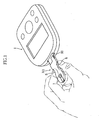
Fig. 1 an overall perspective view of an analyser system according to a first embodiment of the present invention showing the state in which a biosensor is mounted to an analytical apparatus. -
Fig. 2 illustrates the state ofFig. 1 , showing the biosensor in plan and the analytical apparatus in block diagram. -
Fig. 3 is an overall perspective view of the biosensor shown inFigs. 1 and2 . -
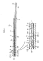
Fig. 4 is a sectional view taken along lines IV-IV inFig. 3 , with the principal portion shown as enlarged. -
Fig. 5 is a plan view showing the disassembled state of the biosensor shown inFig. 3 . -
Fig. 6 is a plan view for illustrating the working electrode and the counter electrode of the biosensor. -
Fig. 7 is a schematic view showing the process of mounting the biosensor to the analytical apparatus, with the biosensor shown in plan and the analytical apparatus shown in block diagram. -
Fig. 8 is a transparent plan view showing a further biosensor to be used in an analyzer system according to a second embodiment of the present invention. -
Fig. 9 is a transparent plan view showing a further biosensor to be used in an analyzer system according to a third embodiment of the present invention. -
Fig. 10 is a transparent plan-view showing a further biosensor to be used in an analyzer system according to a fourth embodiment of the present invention. -
Fig. 11 is a schematic view showing the state in which the biosensor shown inFig. 10 is mounted to the analytical apparatus, with the analytical apparatus shown in circuit block diagram and the biosensor shown in plan view. -
Fig. 12 is a schematic view showing a further biosensor to be used in an analyzer system according to a fifth embodiment of the present invention, with the biosensor shown in plan view and the analytical apparatus shown in circuit block diagram. -
Fig. 13 is a schematic view showing a further biosensor to be used in an analyzer system according to a sixth embodiment of the present invention, with the biosensor shown in plan view and the analytical apparatus shown in circuit block diagram. -
Fig. 14 is a schematic view for illustrating a conventional portable blood glucose level measuring apparatus and a biosensor. - A first through a sixth embodiments of the present invention will be described below with reference to the accompanying drawings.
- First, with reference to
Fig. 1 through Fig. 7 , the first embodiment of the present invention will be described. -
Figs. 1 and2 show a disposable biosensor X1 arranged to be set into aconnector 10 of ananalytical apparatus 1 in use. As shown inFigs. 3 and4 , the biosensor X1 has a plate-like configuration that includes asubstrate 2 and acover 4 stacked on theupper surface 20 of the substrate via aspacer 3. Aflow path 5 and apinch portion 6 are formed in the assembly of the above elements 2-4. - The
spacer 3 determines the dimensions of theflow path 5, and is formed, as shown inFig. 5 , with aslit 30 having an open front end. Theslit 30 defines the width and the length of thepath 5. The openfront end 31 of theslit 30 provides asample inlet 50 for introducing a sample into thepath 5. - As shown in
Fig. 3 through Fig. 5 , thecover 4 includes anair vent 40 and awindow 41. As seen fromFig. 4 , theair vent 40, provided for discharging air in theflow path 5 to the outside, communicates with the interior of theflow path 5. Thewindow 41 is utilized for checking whether or not the sample has been introduced into theflow path 5 and also for checking the movement of the sample in theflow path 5. In a plan view of the biosensor X1, the window is disposed between thesample inlet 50 and theair vent 40. Thewindow 41 may be provided by producing a cutout in thecover 4 and then fitting atransparent member 41B into thecutout 41A. - As shown in
Figs. 5 and6 , thesubstrate 2 is made of an insulating material into a configuration elongated in one direction (longitudinal direction), and is formed with a through-hole 2A at a portion which is not covered by thecover 4. The through-hole 2A provides the analytical apparatus 1 (SeeFigs. 1 and2 ) with information on the biosensor X1, such as lot information. In theanalytical apparatus 1, the lot information can be obtained from checking certain facts, for example, whether the through-hole exists or not, or what size the hole has, or at what position the hole is located. Theupper surface 20 of thesubstrate 2 is formed with a workingelectrode 21, acounter electrode 22, areagent portion 23 and an insulatingfilm 24. - The working
electrode 21 cooperates with thecounter electrode 22 to apply a voltage to the reaction area or field. The workingelectrode 21, as a whole, extends in the longitudinal direction of thesubstrate 2. The workingelectrode 21 has anend 21A adjacent to ashorter edge 25A of thesubstrate 2. When the biosensor X1 is mounted to theanalytical apparatus 1, theend 21A comes into contact with afirst terminal 11 of theanalytical apparatus 1, which will be described later (SeeFig. 2 ). The workingelectrode 21 has anotherend 21B, which is adjacent to anarcuate edge 25B of thesubstrate 2 and extends in the widthwise direction of thesubstrate 2. - The
counter electrode 22, serving as countermeasures against disturbing noise, includes amain line portion 22A and anisland portion 22B projecting from themain line portion 22A, the main line portion being in the form of a hairpin extending along the periphery of thesubstrate 2. Thecounter electrode 22 generally encloses the workingelectrode 21, with theend 21B of the workingelectrode 21 positioned between acorner region 22a of themain line portion 22A and theisland portion 22B. Themain line portion 22A has an end 22Aa located adjacent to theshorter edge 25A of thesubstrate 2. When the biosensor X1 is mounted to theanalytical apparatus 1, the end 22Aa comes into contact with asecond terminal 12, described below, of theanalytical apparatus 1, the end being positioned closer to theshorter edge 25A of thesubstrate 2 than theend 21A of the working electrode 21 (SeeFig. 2 ). In the plan view of the biosensor X1, theisland portion 22B is positioned directly below theair vent 40, and its plan-view area is larger than that of theair vent 40. - The
reagent portion 23 is so formed as to bridge between theend 21B of the workingelectrode 21 and thecorner region 22a of themain line portion 22A. Thereagent portion 23 is in a solid state containing an oxidoreductase and an electron mediator, for example, but can dissolve when a sample is supplied thereto. The kinds of the oxidoreductase and the electron mediator to be used depend on e.g. the kind of the component to be measured. For instance, to measure a glucose level, glucose dehydrogenase or glucose oxidase may be used for the oxidoreductase, and potassium ferricyanide is used for the electron mediator. - As better shown in
Fig. 5 , the insulatingfilm 24 covers most part of the workingelectrode 21 and thecounter electrode 22. In the workingelectrode 21 and thecounter electrode 22, theends 21A and 22Aa, theportions reagent portion 23 is to be formed, and theportions pinch portion 6 are not covered by the insulatingfilm 24 for exposure. The insulatingfilm 24 is formed with a through-hole 24A corresponding in position to theisland portion 22B of thecounter electrode 22, so that a part of theisland portion 22B is exposed, without being covered by the insulatingfilm 24. - In the
flowpath 5, the sample is caused to flow by capillary action, and a reaction field is provided. As better shown inFigs. 4 and5 , theflow path 5 extends in the longitudinal direction of the substrate to cross theend 21B of the workingelectrode 21 and thecorner region 22a of themain line portion 22A. Thereagent portion 23 is provided in theflow path 5. - As better shown in
Fig. 1 , thepinch portion 6 is utilized by the user for holding the biosensor X1 in mounting the biosensor X1 to theanalytical apparatus 1 or detaching the biosensor X1 from theanalytical apparatus 1. As shown inFigs. 3 and5 , thepinch portion 6 is a recess having an arcuate side surface defined bycutouts substrate 2, thespacer 3 and thecover 4. - The
analytical apparatus 1, with which the biosensor X1 is used, performs the analysis of a sample by an electrochemical method. As shown inFigs. 1 and2 , the analytical apparatus includes aconnector 10 to which the biosensor X1 is mounted, and ananalysis circuit 13 for performing computation necessary for the analysis of a particular component in a sample based on the information from theconnector 10. As shown inFig. 2 , theconnector 10 includes a first and asecond terminals first terminal 11 is to come into contact with theend 21A of the workingelectrode 21, whereas thesecond terminal 12 comes into contact with the end 22Aa of thecounter electrode 22. Thefirst terminal 11 and theanalysis circuit 13 are electrically connected to each other through asignal line 14. On thesignal line 14 is provided a current/voltage conversion amplifier 15. The current/voltage conversion amplifier 15 converts information, or current, obtained from the biosensor X1 into a voltage to be inputted into theanalysis circuit 13. Thesecond terminal 12 is connected to ground. - To analyze a sample with use of the biosensor X1, the biosensor X1 is mounted to the
analytical apparatus 1, as shown inFig. 1 for example, and then a sample (typically blood or urine) is introduced through thesample inlet 50. The mounting of the biosensor X1 is performed in a manner such that the biosensor X1 is pinched at thepinch portions 6 by fingers, and then the biosensor X1 is inserted into theconnector 10 of theanalytical apparatus 1, with theshorter edge 25A (Fig. 3 ) leading ahead. - As better shown in
Fig. 2 , when the biosensor X1 is mounted to theanalytical apparatus 1, the ends 21A, 22Aa of the workingelectrode 21 and thecounter electrode 22 come into contact with the first and thesecond terminals analytical apparatus 1. The end 22Aa of thecounter electrode 22 of the biosensor X1 is closer to theshorter edge 25A of thesubstrate 2 than theend 21A of the workingelectrode 21. Therefore, in mounting the biosensor X1 to theanalytical apparatus 1, the end 22Aa of thecounter electrode 22 comes into contact with thesecond terminal 12 as shown inFig. 7 , and then theend 21A of the workingelectrode 21 comes into contact with thefirst electrode 11 as shown inFig. 2 . - As will be understood from
Fig. 4 , the sample supplied to the biosensor X1 flows within theflow path 5 toward theair vent 40 by capillary action and thereby fills theflow path 5. The sample liquid dissolves thereagent portion 23 to produce a liquid phase reaction system in theflow path 5. As will be understood fromFig. 2 , voltage is applied to the liquid phase reaction system by e.g. a DC power source (not shown) of theanalytical apparatus 1 via the first and thesecond terminals analytical apparatus 1, the workingelectrode 21 and thecounter electrode 22. The responsive current obtained is converted into a voltage by the current/voltage conversion amplifier 15 and then into a digital signal by a non-illustrated AD converter and inputted into theanalysis circuit 13. Based on the digital signal corresponding to the responsive current, theanalysis circuit 13 performs computation necessary for the analysis of the sample, such as the determination of the glucose level in blood. - As mentioned above, the biosensor X1 is disposable. Thus, after the computation at the
analysis circuit 13 is completed, the biosensor X1 need be pulled out from theanalytical apparatus 1. The pulling out of the biosensor X1 can be performed with the biosensor X1 pinched with fingers at thepinch portions 6. - In the biosensor X1, the
pinch portion 6 of the biosensor X1 is utilized in mounting the biosensor X1 to theanalytical apparatus 1 or in pulling the biosensor X1 out of theanalytical apparatus 1. This means that, in the biosensor X1, the portion to be held by the user for mounting and detaching the biosensor X1 is predetermined. Accordingly, the biosensor X1 can be readily mounted and detached. Moreover, unintentional adhesion of the sample to the fingers is prevented in pulling out the biosensor X1, which is preferable for attaining good hygiene. Further, thepinch portion 6 is a recess, the slippage of fingers in mounting or detaching the biosensor X1 can be reduced. This feature also contributes to the improvement in usability of the biosensor X1. - As noted above, in mounting the biosensor X1 to the
analytical apparatus 1, static electricity that has built up in a human body may be discharged to the workingelectrode 21 or thecounter electrode 22 of the biosensor X1. Particularly, static electricity tends to be discharged to the workingelectrode 21 and thecounter electrode 22 through theair vent 40. In the biosensor X1, thecounter electrode 22 copes with the problem of such static electricity. Specifically, theisland portion 22B of thecounter electrode 22 is provided directly below theair vent 40 so that the static electricity coming through theair vent 40 is more likely to be conducted into thecounter electrode 22 than into the workingelectrode 21. Since thecounter electrode 22 is connected to ground through thesecond terminal 12 of theanalytical apparatus 1, the static electricity inputted into thecounter electrode 22 is dissipated, through thesecond terminal 12, to ground. As shown inFig. 7 , in mounting the biosensor X1 to theanalytical apparatus 1, the end 22Aa of thecounter electrode 22 comes into contact at an earlier stage than theend 21A of the workingelectrode 21. Thus, the removal of static electricity occurs when the end 22Aa of thecounter electrode 22 comes into contact with thesecond terminal 12, while theend 21A of the workingelectrode 21 has not come into contact with thefirst terminal 11 yet. Then, when theend 21A of the workingelectrode 21 comes into contact with thefirst terminal 11, the static electricity has already been removed from thecounter electrode 22. Therefore, the static electricity charged in thecounter electrode 22 is prevented from being discharged to the workingelectrode 21 and being inputted into theanalytical circuit 13. - Moreover, the
pinch portion 6 is provided in the biosensor X1, and thecounter electrode 22 is exposed from the insulatingfilm 24 at a portion adjacent to thepinch portion 6. Therefore, even when static electricity is built up in the human body, the static electricity is likely to be inputted into thecounter electrode 22 by mounting the biosensor X1 to theanalytical apparatus 1 while holding thepinch portion 6. As a result, the static electricity in the human body is discharged through thecounter electrode 22 without being inputted into the workingelectrode 21 and theanalysis circuit 13. - With use of the biosensor X1, as described above, static electricity is prevented from flowing into the
analysis circuit 13 through the workingelectrode 21 and thefirst terminal 11 of theanalytical apparatus 1. Therefore, it is possible to prevent measurement failure or measurement error due to the static electricity into theanalysis circuit 13. Further, the generation of Joule heat at the workingelectrode 21 due to static electricity can be prevented, whereby the workingelectrode 21 does not melt at a portion contacting thefirst terminal 11 of theanalytical apparatus 1. These advantages are obtained simply by contriving the form of thecounter electrode 22 of the biosensor X1, i.e., without changing the design of theanalytical apparatus 1. Thus, it is advantageous that in coping with the disturbing noise, the structure of theanalytical apparatus 1 does not become complicated, and the size of theanalytical apparatus 1 does not become larger. In an instance where the workingelectrode 21 and thecounter electrode 22 are formed by screen printing, the modification of the electrode can be performed simply by changing the configuration of the opening in a mask. Therefore, the countermeasure against the disturbing noise such as static electricity can be provided without changing the design of the existing manufacturing line, but with a slight increase of the material. This is advantageous in terms of the manufacturing cost. It should be noted that the biosensor X1 removes not only the static electricity coming from a human body but also other disturbing noise. - Next, biosensors to be used in an analyzer system according to second through sixth embodiments of the present invention will be described with reference to
Fig. 8 through Fig. 13 . In these figures, the elements which are identical or similar to those of the biosensor X1 or theanalytical apparatus 1 of the first embodiment (SeeFigs. 1-7 ) are designated by the same reference signs as those used above and description thereof will be omitted. -
Fig. 8 is a transparent plan view showing a biosensor to be used in an analyzer system according to the second embodiment of the present invention. - As shown in
Fig. 8 , the biosensor X2 differs from the above-described biosensor X1 of the first embodiment (See particularlyFig. 6 ) in structure of thecounter electrode 7A. - The
counter electrode 7A serves as a disturbing-noise countermeasure electrode, and includes amain line portion 70A and a pair ofbranches 71A. As viewed in plan, the pairedbranches 71A are arranged at the periphery of theair vent 40 and spaced from each other in the longitudinal direction of thesubstrate 2. As a result, as viewed in plan, thecounter electrode 7A, together with the workingelectrode 21, surrounds theair vent 40. - With such a structure, the
counter electrode 7A can effectively remove static electricity. Particularly, by the provision of the pairedbranches 71A, the static electricity coming through theair vent 40 can be discharged at thecounter electrode 7A. - In the biosensor X2, one of the paired
branches 71A may be dispensed with. -
Fig. 9 is a transparent plan view showing a biosensor forming part of the third embodiment of the present invention. - As shown in
Fig. 9 , the biosensor X3 is similar to the biosensor X2 (SeeFig. 8 ) forming part of the second embodiment of the present invention. Thecounter electrode 7B of the biosensor X3 includes amain line portion 70B and aloop portion 71B. Theloop portion 71B extends out from themain line portion 70B so as to surround theair vent 40. -
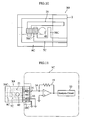
Figs. 10 and 11 show a biosensor forming part of the fourth embodiment of the present invention.Fig. 10 is a transparent plan view of the biosensor.Fig. 11 shows the biosensor in a plan view and the analytical apparatus in a circuit block diagram. - As shown in
Figs. 10 and 11 , the biosensor X4 includes a workingelectrode 21, acounter electrode 7C and anadditional electrode 8C. Thecounter electrode 7C has an F-shaped configuration including a pair ofbranches 70C arranged at the periphery of theair vent 40. Theadditional electrode 8C extends along the periphery of thesubstrate 2 and is U-shaped to surround the workingelectrode 21 and thecounter electrode 7C. - As shown in
Fig. 11 , in addition to the first and thesecond terminals analytical apparatus 1C includes athird terminal 16C for coming into contact with theadditional electrode 8C. Thethird terminal 16C is connected to ground separately from thesecond terminal 12. - Although the
second terminal 12 and thethird terminal 16C are connected to ground separately from each other inFig. 11 , theseterminals - With the above structure, in addition to the
counter electrode 7C, theadditional electrode 8C also serves as a disturbing-noise countermeasure electrode. Specifically, thecounter electrode 7C solely copes with the disturbing noise such as static electricity coming through theair vent 40, whereas theadditional electrode 8C solely copes with the disturbing noise such as static electricity coming through a side surface of the biosensor X4. Thecounter electrode 7C and theadditional electrode 8C are connected to ground when the biosensor X4 is mounted to theanalytical apparatus 1C. Therefore, disturbing noise is dissipated to ground through thecounter electrode 7C and theadditional electrode 8C. In this manner, the input of disturbing noise into the workingelectrode 21, and hence, into theanalysis circuit 13 can be properly prevented. -
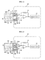
Fig. 12 is a view for illustrating a biosensor forming part of the fifth embodiment of the present invention, with the biosensor and the analytical apparatus shown in plan view and in circuit block diagram, respectively. - The biosensor X5 shown in
Fig. 12 includes twoadditional electrodes electrode 21 and thecounter electrode 7D. The structures of the workingelectrode 21 and thecounter electrode 7D are similar to those of the foregoing biosensor X4 (SeeFigs. 10 and 11 ). The twoadditional electrodes additional electrode 8C (SeeFigs. 10 and 11 ) at thesample inlet 50. Specifically, each of theadditional electrodes analytical apparatus 1D includes a third and afourth terminals additional electrodes terminals - With the above structure, in addition to the
counter electrode 7D, the twoadditional electrodes counter electrode 7D copes with the disturbing noise such as static electricity corning through theair vent 40, whereas the twoadditional electrodes -
Fig. 13 is a view for illustrating a biosensor forming part of the sixth embodiment of the present invention, with the biosensor and the analytical apparatus shown in plan view and in circuit block diagram, respectively. - The biosensor X6 shown in
Fig. 13 includes twoadditional electrodes electrodes prior art biosensor 90 shown inFig. 14 . Theadditional electrode 80E has a configuration similar to that of theadditional electrode 8C (SeeFigs. 10 and 11 ) of the above-described biosensor X4. Specifically, theadditional electrode 80E is U-shaped, extending along the periphery of thesubstrate 2. Theadditional electrode 81E extends from theair vent 40 to ashorter edge 25A of thesubstrate 2 in the longitudinal direction of thesubstrate 2. - The
analytical apparatus 1E includes a third and afourth terminals additional electrodes fourth terminals - In the biosensor X6 shown in
Fig. 13 again, theadditional electrode 80E be divided at thesample inlet 50, as is in the biosensor X5 shown inFig. 12 . - The present invention is not limited to the first through the sixth embodiments described above and may be modified in various ways. Particularly, the number and configuration of disturbing-noise countermeasure electrodes are not limited to the above-described examples and may be modified in various ways.
- Although the biosensor for measuring a single item is exemplarily described in the foregoing embodiments, the present invention is also applicable to an electrochemical sensor designed for measuring a plurality of items such as a glucose level and a cholesterol level in blood.
- In the foregoing embodiments, disturbing noise such as static electricity is removed by dissipation to ground. However, an electronic part or an electric circuit of power consumption may be provided in the analytical apparatus so that disturbing noise can be removed by these components.
Claims (10)
- An analyzer system comprising an analytical tool (X1) and an analytical apparatus (1) which includes a plurality of terminals (11, 12) and an analysis circuit (13), the analytical tool (X1) comprising:a substrate (2);a plurality of electrodes (21, 22), including a working electrode (21) and at least one disturbing-noise countermeasure electrode (22), formed on the substrate (2) for contacting with corresponding terminals (11, 12) when an insertion edge (25A) of the substrate (2) is mounted to the analytical apparatus (1),a flow path (5) for moving a sample, anda cover (4) bonded to the substrate (2) and through which an air vent (40) is formed for discharging air from the flow path (5);wherein the at least one disturbing-noise countermeasure electrode (22) is arranged so that disturbing noise is more likely to come thereto than to the working electrode (21);wherein the disturbing-noise countermeasure electrode (22) includes an input portion (22B) to which disturbing noise coming through the air vent (40) is inputted;wherein the input portion (22B) comprises at least one part (22B, 70C, 71A, 71B) projecting from the disturbing-noise countermeasure electrode (22) and, in plan view, positioned directly below the air vent (40) or located at a periphery of the air vent (4) or surrounding the air vent (40);wherein the plurality of terminals (11, 12) of the analytical apparatus (1) include a ground connection terminal (12) that is connected to ground and an analysis circuit connection terminal (11) that is connected to the analysis circuit, andwherein when the analytical tool (X1) is mounted to the analytical apparatus (1), the disturbing-noise countermeasure electrode (22) comes into contact with the ground connection terminal (12) before the working electrode (21) comes into contact with the analysis circuit connection terminal (11).
- The analyzer system according to claim 1, wherein the disturbing-noise countermeasure electrode (22) is arranged for applying voltage to a target portion in cooperation with the working electrode (21).
- The analyzer system according to claim 2, wherein the disturbing-noise countermeasure electrode (22) is not electrically connected to the analysis circuit (23) when the analytical tool (X1) is mounted to the analytical apparatus (11).
- The analyzer system according to claim 1, wherein the analytical tool (X1) comprises an insulating film (24), and
wherein the insulating film (24) includes an opening (24A) for exposing the input portion (22B) and wherein the input portion comprises a part (22B) projecting from the disturbing-noisecountermeasureelectrode (22) which, in plan view, is positioned directly below the air vent (40). - The analyzer system according to claim 1, wherein the disturbing-noise countermeasure electrode (22) surrounds at least one (21) of the plurality of electrodes.
- The analyzer system according to claim 1, wherein the disturbing-noise countermeasure electrode (22) is formed along a periphery of the substrate (2).
- The analyzer system according to claim 1,
wherein the disturbing-noise countermeasure electrode (22) includes a portion (22Aa) located on the substrate (2) at a position closer to the insertion edge (25A) of the substrate (2) than the other electrodes of the plurality of electrodes (21, 22). - The analyzer system according to claim 1, wherein the at least one part (22B, 70C, 71A, 71B) projecting from the disturbing-noise countermeasure electrode (22) is positioned, in plan view, directly below the air vent (40) and further comprising a pinch portion (6) which is utilized in mounting the analytical tool (X1) to the analytical apparatus (1) or detaching the analytical tool (X1) from the analytical apparatus (1).
- The analyzer system according to claim 8, wherein the disturbing-noise countermeasure electrode (22) is covered by an insulating film (24) except for an exposed portion (22c) adjacent to the pinch portion (6) and the at least one part (22B, 70C, 71A, 71B) positioned directly below the air vent (40).
- The analyzer system according to claim 9, wherein the pinch portion (6) comprises a recess (28) which is inwardly sunk in a plan view of the analytical tool (X1).
Applications Claiming Priority (3)
| Application Number | Priority Date | Filing Date | Title |
|---|---|---|---|
| JP2002350198 | 2002-12-02 | ||
| JP2002350198 | 2002-12-02 | ||
| PCT/JP2003/015358 WO2004051249A1 (en) | 2002-12-02 | 2003-12-01 | Analysis instrument |
Publications (3)
| Publication Number | Publication Date |
|---|---|
| EP1571442A1 EP1571442A1 (en) | 2005-09-07 |
| EP1571442A4 EP1571442A4 (en) | 2011-03-23 |
| EP1571442B1 true EP1571442B1 (en) | 2014-09-17 |
Family
ID=32463073
Family Applications (1)
| Application Number | Title | Priority Date | Filing Date |
|---|---|---|---|
| EP03775991.7A Expired - Lifetime EP1571442B1 (en) | 2002-12-02 | 2003-12-01 | Analyser system |
Country Status (6)
| Country | Link |
|---|---|
| US (1) | US8460523B2 (en) |
| EP (1) | EP1571442B1 (en) |
| JP (1) | JP4352152B2 (en) |
| CN (1) | CN100442047C (en) |
| AU (1) | AU2003284512A1 (en) |
| WO (1) | WO2004051249A1 (en) |
Families Citing this family (15)
| Publication number | Priority date | Publication date | Assignee | Title |
|---|---|---|---|---|
| WO2007026683A1 (en) * | 2005-09-02 | 2007-03-08 | Arkray, Inc. | Method for detecting sample supply condition, and analyzer |
| WO2007133457A2 (en) * | 2006-05-08 | 2007-11-22 | Bayer Healthcare Llc | Electrochemical test sensor with reduced sample volume |
| KR20080080841A (en) * | 2007-03-02 | 2008-09-05 | 주식회사 아이센스 | Electrochemical biosensor |
| US8021528B2 (en) * | 2007-03-07 | 2011-09-20 | Yong-Sang Jang | Biosensor |
| US7794658B2 (en) * | 2007-07-25 | 2010-09-14 | Lifescan, Inc. | Open circuit delay devices, systems, and methods for analyte measurement |
| CA2693497A1 (en) | 2007-07-31 | 2009-02-05 | Bayer Healthcare Llc | Test sensors and method of using side-mounted meter contacts |
| US7943022B2 (en) | 2007-09-04 | 2011-05-17 | Lifescan, Inc. | Analyte test strip with improved reagent deposition |
| JP5234749B2 (en) * | 2007-12-27 | 2013-07-10 | 株式会社堀場製作所 | Test solution analysis chip |
| WO2009119117A1 (en) * | 2008-03-27 | 2009-10-01 | パナソニック株式会社 | Measurement device, measurement system, and concentration measurement method |
| US8187658B2 (en) | 2008-06-24 | 2012-05-29 | Lifescan, Inc. | Method of manufacturing analyte test strip for accepting diverse sample volumes |
| US8178313B2 (en) | 2008-06-24 | 2012-05-15 | Lifescan, Inc. | Method for determining an analyte in a bodily fluid |
| US7922985B2 (en) | 2008-06-24 | 2011-04-12 | Lifescan, Inc. | Analyte test strip for accepting diverse sample volumes |
| US20110186428A1 (en) * | 2010-01-29 | 2011-08-04 | Roche Diagnostics Operations, Inc. | Electrode arrangements for biosensors |
| GB2487416B (en) * | 2011-01-21 | 2013-03-27 | Vagonyx Ltd Of Portcullis Trustnet Bvi Ltd | Chemical sensor |
| JP5813171B2 (en) * | 2013-05-02 | 2015-11-17 | アークレイ株式会社 | Analytical tool, manufacturing method thereof, and measuring device using the same |
Citations (1)
| Publication number | Priority date | Publication date | Assignee | Title |
|---|---|---|---|---|
| WO2003048756A1 (en) * | 2001-12-05 | 2003-06-12 | Matsushita Electric Industrial Co., Ltd. | Biosensor |
Family Cites Families (32)
| Publication number | Priority date | Publication date | Assignee | Title |
|---|---|---|---|---|
| JPS6058541A (en) * | 1983-09-12 | 1985-04-04 | Agency Of Ind Science & Technol | Hardening-reaction-voltage detection device for structure of resin composite mamerial |
| JPH02310457A (en) * | 1989-05-26 | 1990-12-26 | Matsushita Electric Ind Co Ltd | Biosensor |
| JPH0810208B2 (en) * | 1990-07-20 | 1996-01-31 | 松下電器産業株式会社 | Biosensor and biosensor measuring device |
| US5320732A (en) | 1990-07-20 | 1994-06-14 | Matsushita Electric Industrial Co., Ltd. | Biosensor and measuring apparatus using the same |
| US5264103A (en) * | 1991-10-18 | 1993-11-23 | Matsushita Electric Industrial Co., Ltd. | Biosensor and a method for measuring a concentration of a substrate in a sample |
| JP3135959B2 (en) * | 1991-12-12 | 2001-02-19 | アークレイ株式会社 | Biosensor and separation and quantification method using the same |
| ES2153335T3 (en) * | 1993-06-08 | 2006-09-01 | Roche Diagnostics Operations, Inc. | BIOSENSOR METER THAT DETECTS THE PROPER ADJUSTMENT OF THE ELECTRODES AND DISTINGUISHES SAMPLING STRIPS AND CHECKING STRIPS. |
| JP3245301B2 (en) | 1994-06-23 | 2002-01-15 | 新明和工業株式会社 | Garbage truck |
| JPH0810208A (en) | 1994-06-30 | 1996-01-16 | Toshiba Corp | Dishwasher |
| JP3365184B2 (en) | 1996-01-10 | 2003-01-08 | 松下電器産業株式会社 | Biosensor |
| DE19605583A1 (en) * | 1996-02-15 | 1997-08-21 | Bayer Ag | Electrochemical sensors with improved selectivity and increased sensitivity |
| US5980708A (en) * | 1997-02-12 | 1999-11-09 | Champagne; Gilles Y. | High sensitivity multiple waveform voltammetric instrument |
| PT1024358E (en) * | 1997-07-22 | 2009-04-16 | Panasonic Corp | DENSOMETER |
| JP3896435B2 (en) * | 1997-12-17 | 2007-03-22 | アークレイ株式会社 | Sensor and sensor assembly |
| US6287451B1 (en) * | 1999-06-02 | 2001-09-11 | Handani Winarta | Disposable sensor and method of making |
| US6258229B1 (en) | 1999-06-02 | 2001-07-10 | Handani Winarta | Disposable sub-microliter volume sensor and method of making |
| CA2305922C (en) * | 1999-08-02 | 2005-09-20 | Bayer Corporation | Improved electrochemical sensor design |
| JP4226756B2 (en) | 1999-11-15 | 2009-02-18 | パナソニック株式会社 | Biosensor, quantitative method and quantitative apparatus using the same |
| KR100445489B1 (en) * | 1999-11-15 | 2004-08-21 | 마츠시타 덴끼 산교 가부시키가이샤 | Biosensor, method of forming thin-film electrode, and method and apparatus for quantitative determination |
| EP1279033B1 (en) * | 2000-03-22 | 2004-10-06 | All Medicus Co., Ltd | Electrochemical biosensor test strip with recognition electrode and readout meter using this test strip |
| US6858433B1 (en) * | 2000-04-03 | 2005-02-22 | Roche Diagnostics Operations, Inc. | Biosensor electromagnetic noise cancellation |
| US6572745B2 (en) * | 2001-03-23 | 2003-06-03 | Virotek, L.L.C. | Electrochemical sensor and method thereof |
| US6960287B2 (en) * | 2001-06-11 | 2005-11-01 | Bayer Corporation | Underfill detection system for a test sensor |
| CN1373361A (en) * | 2002-04-11 | 2002-10-09 | 复旦大学 | Expandable electrode for measuring blood sugar and its preparing process |
| US6942770B2 (en) * | 2002-04-19 | 2005-09-13 | Nova Biomedical Corporation | Disposable sub-microliter volume biosensor with enhanced sample inlet |
| US6743635B2 (en) * | 2002-04-25 | 2004-06-01 | Home Diagnostics, Inc. | System and methods for blood glucose sensing |
| US6946299B2 (en) | 2002-04-25 | 2005-09-20 | Home Diagnostics, Inc. | Systems and methods for blood glucose sensing |
| JP2004184255A (en) * | 2002-12-04 | 2004-07-02 | Arkray Inc | Analysis equipment |
| US7144485B2 (en) * | 2003-01-13 | 2006-12-05 | Hmd Biomedical Inc. | Strips for analyzing samples |
| EP1593961B1 (en) * | 2003-02-14 | 2013-01-09 | Arkray Inc. | Analyzing tool with knob part |
| JP4357449B2 (en) | 2005-04-26 | 2009-11-04 | 株式会社ルネサステクノロジ | Control method of recording / playback apparatus |
| JP5164724B2 (en) | 2008-08-05 | 2013-03-21 | 日本インシュレーション株式会社 | Calcium silicate with reduced crystalline silica content and method for producing the same |
-
2003
- 2003-12-01 WO PCT/JP2003/015358 patent/WO2004051249A1/en not_active Ceased
- 2003-12-01 US US10/537,708 patent/US8460523B2/en active Active
- 2003-12-01 EP EP03775991.7A patent/EP1571442B1/en not_active Expired - Lifetime
- 2003-12-01 AU AU2003284512A patent/AU2003284512A1/en not_active Abandoned
- 2003-12-01 JP JP2004556875A patent/JP4352152B2/en not_active Expired - Lifetime
- 2003-12-01 CN CNB2003801048756A patent/CN100442047C/en not_active Expired - Lifetime
Patent Citations (2)
| Publication number | Priority date | Publication date | Assignee | Title |
|---|---|---|---|---|
| WO2003048756A1 (en) * | 2001-12-05 | 2003-06-12 | Matsushita Electric Industrial Co., Ltd. | Biosensor |
| EP1452856A1 (en) * | 2001-12-05 | 2004-09-01 | Matsushita Electric Industrial Co., Ltd. | Biosensor |
Also Published As
| Publication number | Publication date |
|---|---|
| WO2004051249A1 (en) | 2004-06-17 |
| US8460523B2 (en) | 2013-06-11 |
| CN1720447A (en) | 2006-01-11 |
| EP1571442A4 (en) | 2011-03-23 |
| CN100442047C (en) | 2008-12-10 |
| EP1571442A1 (en) | 2005-09-07 |
| JPWO2004051249A1 (en) | 2006-04-06 |
| US20060042943A1 (en) | 2006-03-02 |
| AU2003284512A1 (en) | 2004-06-23 |
| JP4352152B2 (en) | 2009-10-28 |
Similar Documents
| Publication | Publication Date | Title |
|---|---|---|
| KR100340174B1 (en) | Electrochemical Biosensor Test Strip, Fabrication Method Thereof and Electrochemical Biosensor | |
| EP1279033B1 (en) | Electrochemical biosensor test strip with recognition electrode and readout meter using this test strip | |
| EP1467201B1 (en) | Analyzer having temperature sensor | |
| CN102918388B (en) | Electrochemical analyte measurement method and system | |
| CN102984999B (en) | For measuring the system and method for sample analyte | |
| JP4814110B2 (en) | Electrochemical biosensor | |
| US8460523B2 (en) | Analysis instrument | |
| EP2589960A1 (en) | Method and Apparatus for Assay of Electrochemical Properties | |
| KR20150013343A (en) | Electrochemical test strip | |
| JPWO2005100968A1 (en) | Analysis equipment | |
| CN104661593B (en) | System and method for measuring the concentration of glucose insensitive to hematocrit | |
| JP2002156358A (en) | Biosensor, notification device, and measurement device | |
| US20060042942A1 (en) | Analyzing device | |
| JPWO2007026683A1 (en) | Sample supply state detection method and analysis tool | |
| EP2900138B1 (en) | System and method for determining hematocrit insensitive glucose concentration | |
| KR100385832B1 (en) | Electrochemical Biosensor Test Strip with Recognition Electrode and Readout Meter using This Test Strip | |
| EP2871471B1 (en) | Measuring apparatus and measuring method | |
| CN100392389C (en) | Electrochemical sensing test piece | |
| US20200033287A1 (en) | Method of operation of a meter | |
| US20080169799A1 (en) | Method for biosensor analysis | |
| KR200435115Y1 (en) | Biosensor for fast sample injection | |
| JP2004004057A (en) | Biosensor, adapter used therefor, and measuring device | |
| AU2013204842B2 (en) | Electrochemical test strip | |
| TWI274876B (en) | Multistage examination method for a biosensor test piece |
Legal Events
| Date | Code | Title | Description |
|---|---|---|---|
| PUAI | Public reference made under article 153(3) epc to a published international application that has entered the european phase |
Free format text: ORIGINAL CODE: 0009012 |
|
| 17P | Request for examination filed |
Effective date: 20050617 |
|
| AK | Designated contracting states |
Kind code of ref document: A1 Designated state(s): AT BE BG CH CY CZ DE DK EE ES FI FR GB GR HU IE IT LI LU MC NL PT RO SE SI SK TR |
|
| AX | Request for extension of the european patent |
Extension state: AL LT LV MK |
|
| DAX | Request for extension of the european patent (deleted) | ||
| A4 | Supplementary search report drawn up and despatched |
Effective date: 20110221 |
|
| 17Q | First examination report despatched |
Effective date: 20110524 |
|
| GRAP | Despatch of communication of intention to grant a patent |
Free format text: ORIGINAL CODE: EPIDOSNIGR1 |
|
| INTG | Intention to grant announced |
Effective date: 20140417 |
|
| GRAS | Grant fee paid |
Free format text: ORIGINAL CODE: EPIDOSNIGR3 |
|
| GRAA | (expected) grant |
Free format text: ORIGINAL CODE: 0009210 |
|
| AK | Designated contracting states |
Kind code of ref document: B1 Designated state(s): AT BE BG CH CY CZ DE DK EE ES FI FR GB GR HU IE IT LI LU MC NL PT RO SE SI SK TR |
|
| REG | Reference to a national code |
Ref country code: GB Ref legal event code: FG4D |
|
| REG | Reference to a national code |
Ref country code: CH Ref legal event code: EP |
|
| REG | Reference to a national code |
Ref country code: IE Ref legal event code: FG4D |
|
| REG | Reference to a national code |
Ref country code: AT Ref legal event code: REF Ref document number: 687921 Country of ref document: AT Kind code of ref document: T Effective date: 20141015 |
|
| REG | Reference to a national code |
Ref country code: DE Ref legal event code: R096 Ref document number: 60346764 Country of ref document: DE Effective date: 20141030 |
|
| PG25 | Lapsed in a contracting state [announced via postgrant information from national office to epo] |
Ref country code: SE Free format text: LAPSE BECAUSE OF FAILURE TO SUBMIT A TRANSLATION OF THE DESCRIPTION OR TO PAY THE FEE WITHIN THE PRESCRIBED TIME-LIMIT Effective date: 20140917 Ref country code: FI Free format text: LAPSE BECAUSE OF FAILURE TO SUBMIT A TRANSLATION OF THE DESCRIPTION OR TO PAY THE FEE WITHIN THE PRESCRIBED TIME-LIMIT Effective date: 20140917 Ref country code: GR Free format text: LAPSE BECAUSE OF FAILURE TO SUBMIT A TRANSLATION OF THE DESCRIPTION OR TO PAY THE FEE WITHIN THE PRESCRIBED TIME-LIMIT Effective date: 20141218 |
|
| REG | Reference to a national code |
Ref country code: NL Ref legal event code: VDEP Effective date: 20140917 |
|
| PG25 | Lapsed in a contracting state [announced via postgrant information from national office to epo] |
Ref country code: CY Free format text: LAPSE BECAUSE OF FAILURE TO SUBMIT A TRANSLATION OF THE DESCRIPTION OR TO PAY THE FEE WITHIN THE PRESCRIBED TIME-LIMIT Effective date: 20140917 |
|
| REG | Reference to a national code |
Ref country code: AT Ref legal event code: MK05 Ref document number: 687921 Country of ref document: AT Kind code of ref document: T Effective date: 20140917 |
|
| PG25 | Lapsed in a contracting state [announced via postgrant information from national office to epo] |
Ref country code: NL Free format text: LAPSE BECAUSE OF FAILURE TO SUBMIT A TRANSLATION OF THE DESCRIPTION OR TO PAY THE FEE WITHIN THE PRESCRIBED TIME-LIMIT Effective date: 20140917 |
|
| PG25 | Lapsed in a contracting state [announced via postgrant information from national office to epo] |
Ref country code: PT Free format text: LAPSE BECAUSE OF FAILURE TO SUBMIT A TRANSLATION OF THE DESCRIPTION OR TO PAY THE FEE WITHIN THE PRESCRIBED TIME-LIMIT Effective date: 20150119 Ref country code: EE Free format text: LAPSE BECAUSE OF FAILURE TO SUBMIT A TRANSLATION OF THE DESCRIPTION OR TO PAY THE FEE WITHIN THE PRESCRIBED TIME-LIMIT Effective date: 20140917 Ref country code: CZ Free format text: LAPSE BECAUSE OF FAILURE TO SUBMIT A TRANSLATION OF THE DESCRIPTION OR TO PAY THE FEE WITHIN THE PRESCRIBED TIME-LIMIT Effective date: 20140917 Ref country code: ES Free format text: LAPSE BECAUSE OF FAILURE TO SUBMIT A TRANSLATION OF THE DESCRIPTION OR TO PAY THE FEE WITHIN THE PRESCRIBED TIME-LIMIT Effective date: 20140917 Ref country code: RO Free format text: LAPSE BECAUSE OF FAILURE TO SUBMIT A TRANSLATION OF THE DESCRIPTION OR TO PAY THE FEE WITHIN THE PRESCRIBED TIME-LIMIT Effective date: 20140917 Ref country code: SK Free format text: LAPSE BECAUSE OF FAILURE TO SUBMIT A TRANSLATION OF THE DESCRIPTION OR TO PAY THE FEE WITHIN THE PRESCRIBED TIME-LIMIT Effective date: 20140917 |
|
| PG25 | Lapsed in a contracting state [announced via postgrant information from national office to epo] |
Ref country code: AT Free format text: LAPSE BECAUSE OF FAILURE TO SUBMIT A TRANSLATION OF THE DESCRIPTION OR TO PAY THE FEE WITHIN THE PRESCRIBED TIME-LIMIT Effective date: 20140917 |
|
| REG | Reference to a national code |
Ref country code: DE Ref legal event code: R097 Ref document number: 60346764 Country of ref document: DE |
|
| PG25 | Lapsed in a contracting state [announced via postgrant information from national office to epo] |
Ref country code: BE Free format text: LAPSE BECAUSE OF NON-PAYMENT OF DUE FEES Effective date: 20141231 |
|
| PLBE | No opposition filed within time limit |
Free format text: ORIGINAL CODE: 0009261 |
|
| STAA | Information on the status of an ep patent application or granted ep patent |
Free format text: STATUS: NO OPPOSITION FILED WITHIN TIME LIMIT |
|
| PG25 | Lapsed in a contracting state [announced via postgrant information from national office to epo] |
Ref country code: LU Free format text: LAPSE BECAUSE OF FAILURE TO SUBMIT A TRANSLATION OF THE DESCRIPTION OR TO PAY THE FEE WITHIN THE PRESCRIBED TIME-LIMIT Effective date: 20141201 Ref country code: DK Free format text: LAPSE BECAUSE OF FAILURE TO SUBMIT A TRANSLATION OF THE DESCRIPTION OR TO PAY THE FEE WITHIN THE PRESCRIBED TIME-LIMIT Effective date: 20140917 |
|
| REG | Reference to a national code |
Ref country code: CH Ref legal event code: PL |
|
| RAP2 | Party data changed (patent owner data changed or rights of a patent transferred) |
Owner name: ARKRAY, INC. |
|
| 26N | No opposition filed |
Effective date: 20150618 |
|
| REG | Reference to a national code |
Ref country code: IE Ref legal event code: MM4A |
|
| PG25 | Lapsed in a contracting state [announced via postgrant information from national office to epo] |
Ref country code: IE Free format text: LAPSE BECAUSE OF NON-PAYMENT OF DUE FEES Effective date: 20141201 Ref country code: CH Free format text: LAPSE BECAUSE OF NON-PAYMENT OF DUE FEES Effective date: 20141231 Ref country code: LI Free format text: LAPSE BECAUSE OF NON-PAYMENT OF DUE FEES Effective date: 20141231 |
|
| PG25 | Lapsed in a contracting state [announced via postgrant information from national office to epo] |
Ref country code: SI Free format text: LAPSE BECAUSE OF FAILURE TO SUBMIT A TRANSLATION OF THE DESCRIPTION OR TO PAY THE FEE WITHIN THE PRESCRIBED TIME-LIMIT Effective date: 20140917 |
|
| REG | Reference to a national code |
Ref country code: FR Ref legal event code: PLFP Year of fee payment: 13 |
|
| PG25 | Lapsed in a contracting state [announced via postgrant information from national office to epo] |
Ref country code: MC Free format text: LAPSE BECAUSE OF FAILURE TO SUBMIT A TRANSLATION OF THE DESCRIPTION OR TO PAY THE FEE WITHIN THE PRESCRIBED TIME-LIMIT Effective date: 20140917 Ref country code: BG Free format text: LAPSE BECAUSE OF FAILURE TO SUBMIT A TRANSLATION OF THE DESCRIPTION OR TO PAY THE FEE WITHIN THE PRESCRIBED TIME-LIMIT Effective date: 20140917 |
|
| PG25 | Lapsed in a contracting state [announced via postgrant information from national office to epo] |
Ref country code: TR Free format text: LAPSE BECAUSE OF FAILURE TO SUBMIT A TRANSLATION OF THE DESCRIPTION OR TO PAY THE FEE WITHIN THE PRESCRIBED TIME-LIMIT Effective date: 20140917 Ref country code: HU Free format text: LAPSE BECAUSE OF FAILURE TO SUBMIT A TRANSLATION OF THE DESCRIPTION OR TO PAY THE FEE WITHIN THE PRESCRIBED TIME-LIMIT; INVALID AB INITIO Effective date: 20031201 |
|
| REG | Reference to a national code |
Ref country code: FR Ref legal event code: PLFP Year of fee payment: 14 |
|
| REG | Reference to a national code |
Ref country code: FR Ref legal event code: PLFP Year of fee payment: 15 |
|
| PGFP | Annual fee paid to national office [announced via postgrant information from national office to epo] |
Ref country code: GB Payment date: 20221222 Year of fee payment: 20 Ref country code: FR Payment date: 20221222 Year of fee payment: 20 Ref country code: DE Payment date: 20220620 Year of fee payment: 20 |
|
| PGFP | Annual fee paid to national office [announced via postgrant information from national office to epo] |
Ref country code: IT Payment date: 20221228 Year of fee payment: 20 |
|
| REG | Reference to a national code |
Ref country code: DE Ref legal event code: R071 Ref document number: 60346764 Country of ref document: DE |
|
| REG | Reference to a national code |
Ref country code: GB Ref legal event code: PE20 Expiry date: 20231130 |
|
| PG25 | Lapsed in a contracting state [announced via postgrant information from national office to epo] |
Ref country code: GB Free format text: LAPSE BECAUSE OF EXPIRATION OF PROTECTION Effective date: 20231130 |
|
| PG25 | Lapsed in a contracting state [announced via postgrant information from national office to epo] |
Ref country code: GB Free format text: LAPSE BECAUSE OF EXPIRATION OF PROTECTION Effective date: 20231130 |