EP1571425B1 - Magnetostrictive displacement sensor - Google Patents
Magnetostrictive displacement sensor Download PDFInfo
- Publication number
- EP1571425B1 EP1571425B1 EP04026535A EP04026535A EP1571425B1 EP 1571425 B1 EP1571425 B1 EP 1571425B1 EP 04026535 A EP04026535 A EP 04026535A EP 04026535 A EP04026535 A EP 04026535A EP 1571425 B1 EP1571425 B1 EP 1571425B1
- Authority
- EP
- European Patent Office
- Prior art keywords
- sensor according
- output
- elongation
- housing
- elongation sensor
- Prior art date
- Legal status (The legal status is an assumption and is not a legal conclusion. Google has not performed a legal analysis and makes no representation as to the accuracy of the status listed.)
- Revoked
Links
- 238000006073 displacement reaction Methods 0.000 title 1
- 230000001419 dependent effect Effects 0.000 claims abstract description 14
- 238000012544 monitoring process Methods 0.000 claims abstract description 5
- 238000005259 measurement Methods 0.000 claims description 13
- 230000003287 optical effect Effects 0.000 claims description 13
- 238000007789 sealing Methods 0.000 claims description 12
- 230000008859 change Effects 0.000 claims description 9
- 239000002184 metal Substances 0.000 claims description 7
- 239000004020 conductor Substances 0.000 claims description 4
- 238000012545 processing Methods 0.000 claims description 4
- 239000012811 non-conductive material Substances 0.000 claims description 2
- 230000008054 signal transmission Effects 0.000 claims description 2
- 239000012780 transparent material Substances 0.000 claims description 2
- 238000010397 one-hybrid screening Methods 0.000 claims 1
- IHQKEDIOMGYHEB-UHFFFAOYSA-M sodium dimethylarsinate Chemical class [Na+].C[As](C)([O-])=O IHQKEDIOMGYHEB-UHFFFAOYSA-M 0.000 claims 1
- 238000003745 diagnosis Methods 0.000 abstract description 6
- 238000004519 manufacturing process Methods 0.000 description 9
- 230000003750 conditioning effect Effects 0.000 description 8
- 238000001514 detection method Methods 0.000 description 7
- 230000035939 shock Effects 0.000 description 7
- 238000013461 design Methods 0.000 description 5
- 230000006870 function Effects 0.000 description 4
- 238000012935 Averaging Methods 0.000 description 3
- 230000002950 deficient Effects 0.000 description 3
- 239000007788 liquid Substances 0.000 description 3
- 238000000034 method Methods 0.000 description 3
- 230000035945 sensitivity Effects 0.000 description 3
- 230000000712 assembly Effects 0.000 description 2
- 238000000429 assembly Methods 0.000 description 2
- 238000010276 construction Methods 0.000 description 2
- 230000007613 environmental effect Effects 0.000 description 2
- 238000003780 insertion Methods 0.000 description 2
- 230000037431 insertion Effects 0.000 description 2
- 238000009434 installation Methods 0.000 description 2
- 238000012423 maintenance Methods 0.000 description 2
- 239000000463 material Substances 0.000 description 2
- 230000001681 protective effect Effects 0.000 description 2
- 235000014676 Phragmites communis Nutrition 0.000 description 1
- 230000009471 action Effects 0.000 description 1
- 238000004891 communication Methods 0.000 description 1
- 238000001816 cooling Methods 0.000 description 1
- 230000001934 delay Effects 0.000 description 1
- 238000005553 drilling Methods 0.000 description 1
- 230000000694 effects Effects 0.000 description 1
- 230000005284 excitation Effects 0.000 description 1
- 239000002360 explosive Substances 0.000 description 1
- 239000003292 glue Substances 0.000 description 1
- 230000036039 immunity Effects 0.000 description 1
- 239000011810 insulating material Substances 0.000 description 1
- 238000009413 insulation Methods 0.000 description 1
- 230000007774 longterm Effects 0.000 description 1
- 230000007246 mechanism Effects 0.000 description 1
- 238000000465 moulding Methods 0.000 description 1
- 239000003921 oil Substances 0.000 description 1
- 238000012856 packing Methods 0.000 description 1
- 230000035515 penetration Effects 0.000 description 1
- 238000002360 preparation method Methods 0.000 description 1
- 230000008569 process Effects 0.000 description 1
- 230000000717 retained effect Effects 0.000 description 1
- 230000001360 synchronised effect Effects 0.000 description 1
- 238000012549 training Methods 0.000 description 1
- 238000012546 transfer Methods 0.000 description 1
- 230000001960 triggered effect Effects 0.000 description 1
- 238000013024 troubleshooting Methods 0.000 description 1
- 238000003466 welding Methods 0.000 description 1
Images


Classifications
-
- G—PHYSICS
- G01—MEASURING; TESTING
- G01D—MEASURING NOT SPECIALLY ADAPTED FOR A SPECIFIC VARIABLE; ARRANGEMENTS FOR MEASURING TWO OR MORE VARIABLES NOT COVERED IN A SINGLE OTHER SUBCLASS; TARIFF METERING APPARATUS; MEASURING OR TESTING NOT OTHERWISE PROVIDED FOR
- G01D5/00—Mechanical means for transferring the output of a sensing member; Means for converting the output of a sensing member to another variable where the form or nature of the sensing member does not constrain the means for converting; Transducers not specially adapted for a specific variable
- G01D5/48—Mechanical means for transferring the output of a sensing member; Means for converting the output of a sensing member to another variable where the form or nature of the sensing member does not constrain the means for converting; Transducers not specially adapted for a specific variable using wave or particle radiation means
- G01D5/485—Mechanical means for transferring the output of a sensing member; Means for converting the output of a sensing member to another variable where the form or nature of the sensing member does not constrain the means for converting; Transducers not specially adapted for a specific variable using wave or particle radiation means using magnetostrictive devices
Definitions
- the invention relates to a magnetostrictive path sensor for outputting a distance-dependent signal with a magnetic-field-sensitive sensor element, according to the preamble of claim 1.
- Such track sensors are widely known in the art, including, for example, the DE 102 01 880 A1 is referenced
- the US Pat. No. 6,434,516 B1 describes a method and a device with a differential frequency generator, which converts a measurement signal into a differential signal and feeds it to a controller.
- the US 6,351,117 B1 describes a method and an apparatus for generating an output signal of a transmitter for a magnetostrictive path sensor.
- the US 5,206,586 describes a magnetostrictive transmitter for position detection.
- such a magnetostrictive path sensor has a wire or tubular waveguide made of magnetostrictive material extending in the measuring direction.
- a contactless brought close to the waveguide position magnets is triggered by superposition of magnetic fields, a mechanically elastic wave which propagates in both directions along the waveguide and at its end can be detected. Due to the defined transit time, the exact distance of the position magnet from the end of the waveguide can be determined and thus the position of a movable assembly to which the position magnet is attached.
- the waveguide is received in a support body, eg a tube, in order to achieve a mechanically stable support and to enable an arrangement on a corresponding component.
- the electronic components are arranged at one end of the waveguide, such as a detector coil, a Villary ribbon, a signal conditioning and optionally a diagnostic output. These elements are housed in a housing and thus protected against the environment.
- sensors with a BUS interface sometimes require optical diagnostic outputs.
- optical diagnostic outputs relate exclusively to the BUS communication.
- the present invention seeks to provide a route sensor specified type, which allows a fast and accurate identification of a defective part.
- the route sensor can be placed in a programming mode and that the diagnostic output comprises at least one detection element for the function sensor element detects the magnet.
- a detection element for the function route sensor is also provided in the programming mode.
- a voltage monitoring detection element having at least two non-zero voltage values is provided.
- the diagnostic output comprises an infrared interface.
- the diagnostic output comprises an optical output element, in particular in the wavelength range of visible light.
- the diagnostic output has at least two detection elements according to claims 1 to 3.
- optical diagnosis considerably simplifies the troubleshooting of the corresponding system or component, whereby diagnosed errors or incorrect operation can be uniquely assigned and identified. It is therefore, for example, only the exchange of exactly determined sensor required. A superfluous replacement of sensors that are erroneously considered defective is no longer necessary.
- the voltage monitoring it is possible for example by the voltage monitoring to determine whether or not voltage is applied and whether the voltage is within the allowable range or not. It can also be determined whether, for example, after the programming of the sensor, the programming has been completed, which is required for the desired function of the sensor, or if the sensor is still in the programming mode, so that it must first be completed before the sensor can fulfill the actual task. It can also be determined by the invention whether the magnet located on the component to be monitored is positioned too far away or even positioned outside the measuring range. The corresponding data can be read, for example, via the infrared interface with a Palm or similar electronic component, whereby not only the fact of the error but also the value of the error can be detected.
- sensors are known with one-piece boards, such training lead to sensors with large volumes and with increased shock and vibration sensitivity. If the sensor electronics are distributed over several boards, on the one hand the danger increases that wiring errors occur during production, on the other hand the connecting lines can act as antennas and couple interference signals into the sensor, which leads to an increased sensitivity in the area of EMC. It can also lead to shock cable breaks. In the prior art, it is known to connect individual electronic assemblies and the sensor element via cables with connectors with each other.
- the invention provides a solution in which a compact electronic structure is achieved, wherein by the completely wireless construction minimal circuit volume and maximum shock and vibration resistance is achieved while reducing the susceptibility to interference and high reliability is achieved in production. To achieve these advantages, it is also provided that at least the signal transmission is cable-free.
- At least one of the electrical connections is designed as a plug connection.
- the signal generator is connected in a cable-free manner to a first circuit board with which a second circuit board with signal conditioning elements and a third circuit board with output signal generator elements are plug-connected.
- the three boards are connected by connectors, each connecting all three boards together.
- the three boards are aligned parallel to each other, wherein the first board between the second and third circuit board is arranged and the electronic elements respectively on the side of the second or third board are arranged, which faces the first board.
- a band filter is arranged on the first circuit board.
- the first circuit board is connected directly to the waveguide of the signal generator.
- the third circuit board is plugged into a fourth circuit board carrying the interconnection wiring elements.
- the fourth circuit board on the side facing away from the signal generator side of the existing from the first to third board component is arranged at right angles to these boards, so that the marginal edges of the first to third board of the signal generator facing surface of the fourth board are adjacent ,
- the individual boards which carry the corresponding electronic components, are brought together in a compact form and plugged together, so that a compact volume of the entire assembly is formed.
- the invention further provides a route sensor, wherein the signal conditioning detects an output of the signal generator, which is designed as a Villary transformer and forms a distance-dependent value.
- the signal conditioning detects an output of the signal generator, which is designed as a Villary transformer and forms a distance-dependent value.
- the output of the Villary transformer via amplifier stages becomes a comparator for further digital processing fed. It is also known to amplify the raw signal very high, which is considered advantageous due to the poor signal-to-noise ratio. Any filters should then filter out the interference signals.
- the invention proposes that between signal conditioning and sensor element, e.g. a waveguide, a passive band filter is connected.
- a corresponding electrical filter which minimizes the influence of the environmental influences (shock and vibration). Shock and vibration generate low-frequency superpositions that affect the measurement signal. These frequencies can be filtered out by the bandpass filter so that the measured value influences caused by the environmental influences can be eliminated.
- the bandpass filter is a high pass.
- the band filter is arranged with the Villary transformer on a common carrier, in particular a common board.
- the bandpass filter is a shock and / or vibration filter.
- the invention further relates to a track sensor, wherein the Signal processing detects an output of the signal generator and forms a distance-dependent value and provides as an output signal.
- sensors are often exposed to electromagnetic interference, often caused by drives, frequency converters or welding equipment. In part, these disturbances also exceed the prescribed limits, which requires further protection mechanisms.
- the invention therefore proposes that the sensor element is surrounded by a first shield, in particular a housing made of electrically conductive material, preferably sheet metal, that of an insulating sheath and a second shield, in particular a housing of electrically conductive material , preferably sheet metal, is surrounded, wherein the displaceable magnet is arranged outside the second shield.
- the signal generator and the signal conditioning are arranged on a common carrier within the first shield.
- the common carrier is a printed circuit board or a hybrid circuit.
- the board in particular also the first to fourth board, are inserted in a preferably the first shield forming housing, which is preferably surrounded by the second shield.
- the housing preferably forming the first shield has guide grooves for insertion, guiding and holding of the boards.
- auxiliary housing made of electrically non-conductive material, which is surrounded by the first shield.
- the protection for the degree of protection IP67 is often insufficient if, for example, sensors are used on machines where drilling or cooling liquids are used. Furthermore, age-related processes cause the Degree of protection often worsens after a short period of use.
- this flat gaskets or the like are arranged between the housing parts, wherein, for example, oils in flat gaskets with low contact pressure on capillary action can easily penetrate into the interior of the sensor.
- the housing is designed as an open hollow profile and closed at the end by cover parts and that between the cover parts and the respective housing mouth a profile seal is arranged, on the one hand a first area between the end edge of the housing and the lid and on the other hand, a second area between the mouth-side housing wall region and a protruding into the housing mouth projection of the lid seals.
- the seal has a flat sealing area in the first sealing area, at the radially inner edge of a sealing lip is excluded as a second sealing area, which is directed radially outward.
- the cover is fastened by means of screws to the housing, wherein the seal preferably the second sealing region, the Through holes for the screws radially inside surrounds.
- the invention further relates to a route sensor, wherein in the housing an optical signal transmitter is arranged, which is associated with an optically transparent housing portion which is formed by a fitted into a recess of the housing or the housing cover fitting of optically transmissive material.
- optically permeable molding is sealed by means of a seal against the recess.
- the fitting has a circumferential groove into which the seal, preferably an O-ring, is inserted, wherein the seal is preferably supported under elastic bias on the jar surrounding the fitting of the recess.
- the fitting inserted into the recess is caulked to the recess.
- the shaped piece is fitted flush into the recess, so that it does not protrude beyond the housing wall or cover wall to the outside, and that the molded piece protrudes on the inside of the housing or cover over the wall and is tapered in the projecting area, so that it is fixed in a secure position.
- the invention further relates to a route sensor according to, wherein at least one plug-in output to a housing part, in particular on a cover of the housing, is provided, the output is designed as a plug or socket and the shield is connected to the shielded housing or lid.
- a route sensor according to, wherein at least one plug-in output to a housing part, in particular on a cover of the housing, is provided, the output is designed as a plug or socket and the shield is connected to the shielded housing or lid.
- the outer shield and / or the terminal fuse of the output is integrally connected to the housing part.
- the output has a socket with internal or external thread or is formed by this, wherein the nozzle is integrally formed on the metallic housing part or the metallic lid.
- the metallic lid has a plurality of integrally formed sockets.
- connector and housing cover or the like housing part eliminates the male connector or the like with the housing, which allows a higher packing density in multiple plug connections. Further deleted one sealing edge per plug-in connection, which increases the reliability of the degree of protection during operation.
- the invention further provides a route sensor, wherein the route sensor has at least one signal output, which is led out of the housing.
- a programmer be connected or connectable to the signal output, by means of which the sensor is programmable, in particular for analog output signals.
- the signal lines of the signal output are short-circuit and foreign voltage resistant.
- the signal output has a sensor, by means of which the output line is monitored, so that when feeding of input signals or data, the sensor is switched to a programming mode and is switched in the absence of input signals in the measurement mode for output signals, optionally combined with a time delay element.
- the change of operating mode is effected by external voltage, short circuit or modulated serial data.
- a time window is installed for the mode change.
- the signal output includes a sensor which monitors the output line. If input signals (data) are fed to the output line, the sensor switches to the programming mode.
- the sensor switches into the measuring mode for output signals after switching on, if no input signals are detected, possibly after a short period of time, which is predetermined by a time window.
- the signal lines for the measured value monitoring are monitored by the sensor. If the sensor detects that a programming device is connected to the signal lines, it switches to the programming mode. This mode change can be done by external voltage, short circuit or modulated serial data. For reasons of operational safety, it makes sense to allow this mode change only within a certain time window after switching on. This is not mandatory.
- the senor detects the connected programmer, for example, a PC or a hand-held programmer.
- diagnostic data can be called up via a single-wire bus with analog output or via a four-wire or two-wire bus with binary output, outputs can be parameterized and adjusted.
- the degree of protection of the sensor is not violated during a final adjustment in the field, ie on site. Removal of the sensor is not required. Adjustment, parameter setting and sensor diagnostics can be carried out at any point on the line between the sensor and the controller, for example in the control cabinet, so that even difficult-to-access sensors can be readjusted.
- Minor adjustments such as setting the zero point are set in production at the adjustment points by adjusting mechanical or digital potentiometers, changing components such as resistors, switches or bridges.
- the optical interface makes it possible to transfer at least one of the functions from the specified group.
- the output of diagnostic information is possible, such as version number, serial number, date of manufacture, measuring rate, transit time constant, memory error, position sensor is missing, voltage of the auxiliary power, voltage of the sensor element.
- a measured value output via the interface is transferable.
- the signal type of the output (read and change), start / stop pulse width modulation, analog signals 0 to 10 V, -10 to +10 V, 0 to 20 mA, 4 to 20 mA are possible.
- the output signal can also be adapted (changed) via the interface, as well as a zero point adjustment and end value adjustment.
- a pulse width adjustment, the reflection type of the start signal and an external or free-running measurement can be transmitted.
- an averaging over 1 to n measurements (read and change) is also possible via the interface.
- the invention allows a simplified spare parts inventory, with an adjustment on site with the simplest means is possible and in Fault a detailed diagnosis can be queried. The degree of protection is retained for all types of adjustment. Removal and opening of the sensor is not required.
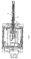
- FIG. 1 and 2 In general, a magnetostrictive path sensor for outputting a distance-dependent signal is shown.
- a protective tube 1 a waveguide 2, wherein the protective tube is still surrounded by a support body 3.
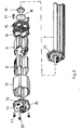
- the electronic components are essentially united in one element, which in FIGS. 3 and 4 is shown.
- This element includes the electronic components as well as a Villary ribbon and a detector coil.
- the component shown is a combination of a first circuit board 4 connected to the signal generator arranged at 1, on which a band filter is optionally applied, a second circuit board 5 with signal conditioning elements 6, a third circuit board 7 with output signal generating elements 8 and a fourth circuit board 9 with a InterconnectionsBesciens.
- the first board 4 is connected directly to the waveguide system. All boards are plug-connected with each other, the boards 4,5,7 are arranged at a distance one above the other rectified and interconnected by connectors 10.
- the board 9 is arranged at right angles to the board package (4, 5, 7), so that overall a very compact board package is formed.
- FIGS. 3 and 4 shown element is surrounded by a Isolierstoffmantel and this in turn is surrounded by a first shield 11 in the form of a housing.
- a form-like sleeve 12 is pushed from insulating material, on which in turn a second shield 13 is pushed in the form of a metallic housing part.
- the unit thus formed is closed at the ends by lids 14,15, which are arranged sealed with the interposition of a seal 16.
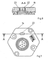
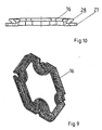
- a corresponding cover and seal arrangement is in FIGS. 7 to 10 shown.
- the connection of the lid 14 and 15 with the housing part 13 by means of screws 17, optionally still a sealing ring 18 and a fastener 19 are provided, and screws 20 which are passed through the housing 13 and screwed beyond the housing with a cover 21 are.
- the housing part 11 may have guide and insertion grooves, in which the edges of the boards 5 and 7 engage appropriately.
- the seals 16 are formed as multi-stage gaskets, which engage on the one hand with a region 27 between the end faces of the housing and lid and on the other hand engage with a second region 28 in the housing and are supported on the inside of the housing. Such as in FIG. 8 shown, engages the corresponding cover 14 partially in the seal, wherein the seal 16 through holes for the Has screws and the sealing area 28 surrounds these holes radially inward.
- an optically transmissive housing portion 22 is formed, behind which an optical signal transmitter is arranged.
- the permeable housing region 22 is a fitting of optically transparent material, which is fitted into a recess of the cover 14 and which is sealed off from the recess of the cover 14 by means of a seal 23.
- the mold piece circumferentially on an annular groove into which the seal 23, preferably an O-ring is inserted, wherein the seal 23 is preferably supported under elastic bias on the mold surrounding the reveal of the recess 14 of the lid.
- the fitting is cammed on the inside of the recess.
- a differently designed lid is provided, which also bears the reference numeral 14.
- This cover has two pluggable outputs, one of which is designed as a plug and the other as a socket.
- the outer shield 24,25 is integrally formed with the housing part (14), so that no additional sealing or connection of shielding elements is required. Due to the space savings thus achieved, it is possible to provide on the lid 14 readily two such elements.
- FIGS. 11 and 12 is generally shown the sensor, wherein the sensor has an optical Signal output, which is identified by the arrow 26.
- the sensor is connected via a connecting line to a (PLC) controller 29.
- PLC PLC
- a T-connector 30 is turned on, to which a hand-held programmer 31 is plugged.
- an interface 32 and a PC 34 are connected. In this way, the parameterization and data acquisition is possible in a simple manner.
- an optical output 26 is also provided, wherein, for example via a hand-held programmer 33, a diagnosis or an adjustment can be made wirelessly.
Abstract
Description
Die Erfindung betrifft einen magnetostriktiven Streckensensor zur Abgabe eines streckenabhängigen Signals mit einem magnetfeldempfindlichen Sensorelement, gemäß Oberbegriff des Anspruches 1.The invention relates to a magnetostrictive path sensor for outputting a distance-dependent signal with a magnetic-field-sensitive sensor element, according to the preamble of
Derartige Streckensensoren sind im Stand der Technik vielfach bekannt, wozu beispielsweise auf die
Die
Die
Die
Die
Ähnliche Messumformer beschreiben die
Ein solcher magnetostriktiver Streckensensor weist in der Regel einen draht- oder rohrförmigen in Messrichtung verlaufenden Wellenleiter aus magnetostriktivem Material auf. Durch einen kontaktlos nah an den Wellenleiter herangebrachten Positionsmagneten wird mittels Überlagerung von Magnetfeldern eine mechanisch- elastische Welle ausgelöst, die sich in beiden Richtungen entlang des Wellenleiters ausbreitet und an dessen Ende detektiert werden kann. Aufgrund der definierten Laufzeit kann die exakte Entfernung des Positionsmagneten von dem Ende des Wellenleiters bestimmt werden und damit die Position einer beweglichen Baugruppe, an welcher der Positionsmagnet befestigt ist. Bekanntermaßen wird der Wellenleiter in einem Stützkörper, z.B. einem Rohr aufgenommen, um eine mechanisch stabile Halterung zu erreichen und eine Anordnung an einem entsprechenden Bauteil zu ermöglichen. Die elektronischen Bauteile sind an einem Ende des Wellenleiters angeordnet, so beispielsweise eine Detektorspule, ein Villary-Bändchen, eine Signalaufbereitung und gegebenenfalls eine Diagnoseausgabe. Diese Elemente sind in einem Gehäuse untergebracht und damit gegen die Umgebung geschützt.As a rule, such a magnetostrictive path sensor has a wire or tubular waveguide made of magnetostrictive material extending in the measuring direction. By a contactless brought close to the waveguide position magnets is triggered by superposition of magnetic fields, a mechanically elastic wave which propagates in both directions along the waveguide and at its end can be detected. Due to the defined transit time, the exact distance of the position magnet from the end of the waveguide can be determined and thus the position of a movable assembly to which the position magnet is attached. As is known, the waveguide is received in a support body, eg a tube, in order to achieve a mechanically stable support and to enable an arrangement on a corresponding component. The electronic components are arranged at one end of the waveguide, such as a detector coil, a Villary ribbon, a signal conditioning and optionally a diagnostic output. These elements are housed in a housing and thus protected against the environment.
An einer entsprechenden zu überwachenden Maschine sind häufig mehrere solcher Streckensensoren angeordnet. Bei Maschinenstillstand ist es wichtig, das gegebenenfalls defekte Teil in der Anlage oder Maschine möglichst schnell zu identifizieren, um so die Kosten, die durch Produktionsausfall verursacht werden, gering zu halten. Sowohl bei der Inbetriebnahme als auch bei Wartungsarbeiten ergeben sich häufig Verzögerungen, weil die einzelnen Makrokomponenten einer Anlage keine oder zu allgemeine oder auch mehrdeutige Diagnosemeldungen abgeben.At a corresponding machine to be monitored several such track sensors are often arranged. In the event of machine downtime, it is important to identify any defective part in the system or machine as quickly as possible in order to minimize the costs of production downtime. There are often delays both during commissioning and during maintenance work because the individual macrocomponents of a system do not give any or too general or even ambiguous diagnostic messages.
Im Stand der Technik sind bei Sensoren mit BUS-Interface zum Teil optische Diagnoseausgaben vorgeschrieben. Diese beziehen sich aber ausschließlich auf die BUS- Kommunikation.In the prior art, sensors with a BUS interface sometimes require optical diagnostic outputs. However, these relate exclusively to the BUS communication.
Ausgehend von diesem Stand der Technik liegt der Erfindung die Aufgabe zugrunde, einen Streckensensor angegebener Art zu schaffen, der eine schnelle und genaue Identifikation eines defekten Teiles ermöglicht.Based on this prior art, the present invention seeks to provide a route sensor specified type, which allows a fast and accurate identification of a defective part.
Zur Lösung dieser Aufgabe wird vorgeschlagen, dass der Streckensensor in einen Programmiermodus setzbar ist und dass die Diagnoseausgabe mindestens ein Erfassungselement für die Funktion Sensorelement erkennt den Magneten umfasst.To solve this problem, it is proposed that the route sensor can be placed in a programming mode and that the diagnostic output comprises at least one detection element for the function sensor element detects the magnet.
Vorzugsweise ist zudem ein Erfassungselement für die Funktion Streckensensor befindet sich im Programmiermodus vorgesehen.Preferably, a detection element for the function route sensor is also provided in the programming mode.
Des Weiteren ist ein Erfassungselement für die Spannungsüberwachung mit mindestens zwei Spannungswerten ungleich Null vorgesehen.Furthermore, a voltage monitoring detection element having at least two non-zero voltage values is provided.
Bevorzugt ist dabei vorgesehen, dass die Diagnoseausgabe eine Infrarot- Schnittstelle umfasst.It is preferably provided that the diagnostic output comprises an infrared interface.
Des Weiteren kann bevorzugt sein, dass die Diagnoseausgabe ein optisches Ausgabeelement, insbesondere im Wellenlängenbereich des sichtbaren Lichts, umfasst.Furthermore, it may be preferred that the diagnostic output comprises an optical output element, in particular in the wavelength range of visible light.
Zudem ist bevorzugt, dass die Diagnoseausgabe mindestens zwei Erfassungselemente gemäß Anspruch 1 bis 3 aufweist.In addition, it is preferred that the diagnostic output has at least two detection elements according to
Durch die auf diese Weise differenzierte optische Diagnose wird die Fehlersuche an der entsprechenden Anlage oder dem Bauteil erheblich vereinfacht, wobei diagnostizierte Fehler oder Fehlbedienungen eindeutig zugeordnet und identifiziert werden können. Es ist daher beispielsweise nur der Austausch des exakt ermittelten Sensors erforderlich. Ein überflüssiger Austausch von Sensoren, die fälschlicher Weise als defekt angesehen werden, ist nicht mehr erforderlich.The thus differentiated optical diagnosis considerably simplifies the troubleshooting of the corresponding system or component, whereby diagnosed errors or incorrect operation can be uniquely assigned and identified. It is therefore, for example, only the exchange of exactly determined sensor required. A superfluous replacement of sensors that are erroneously considered defective is no longer necessary.
Gemäß der Erfindung ist es beispielsweise durch die Spannungsüberwachung möglich, festzustellen, ob Spannung anliegt oder nicht und ob sich die Spannung im zulässigen Bereich befindet oder nicht. Auch kann festgestellt werden, ob beispielsweise nach der Programmierung des Sensors die Programmierung abgeschlossen wurde, was für die gewünschte Funktion des Sensors erforderlich ist, oder aber ob sich der Sensor noch im Programmiermodus befindet, so dass dieser zunächst abgeschlossen werden muss, bevor der Sensor seine eigentliche Aufgabe erfüllen kann. Auch kann durch die Erfindung festgestellt werden, ob der an dem zu überwachenden Bauteil befindliche Magnet zu weit weg positioniert ist oder gar außerhalb des Messbereiches positioniert ist. Die entsprechenden Daten können beispielsweise über die Infrarot-Schnittstelle mit einem Palm oder einem ähnlichen elektronischen Bauteil ausgelesen werden, wobei nicht nur die Tatsache des Fehlers, sondern auch der Wert des Fehlers erfasst werden kann.According to the invention, it is possible for example by the voltage monitoring to determine whether or not voltage is applied and whether the voltage is within the allowable range or not. It can also be determined whether, for example, after the programming of the sensor, the programming has been completed, which is required for the desired function of the sensor, or if the sensor is still in the programming mode, so that it must first be completed before the sensor can fulfill the actual task. It can also be determined by the invention whether the magnet located on the component to be monitored is positioned too far away or even positioned outside the measuring range. The corresponding data can be read, for example, via the infrared interface with a Palm or similar electronic component, whereby not only the fact of the error but also the value of the error can be detected.
Um bei einem Streckensensor nach dem Oberbegriff des Anspruches 1, bei dem die Signalaufbereitung eine Ausgabe des Signalerzeugers erfasst und einen streckenabhängigen Wert daraus ableitet oder bildet, der Streckensensor einen Ausgangssignalerzeuger aufweist, der den streckenabhängigen Wert in ein digitales oder analoges Ausgangssignal umsetzt und eine Interconnections- Beschaltung aufweist, die zwischen dem Ausgangssignalerzeuger und einen Ausgang zur Ausgabe des streckenabhängigen Signale geschaltet ist, die Schock- und Vibrationsempfindlichkeit herabzusetzen und eine Einkopplung von Störsignalen zu vermeiden, wird vorgeschlagen, dass mindestens eine der elektrischen Verbindungen zwischen
- Signalerzeuger und Signalaufbereitung,
- Ausgangssignalerzeuger und InterconnectionsBeschaltung
- Signal generator and signal conditioning,
- Output signal generator and interconnection circuit
Im Stand der Technik sind Sensoren mit einteiligen Platinen bekannt, wobei solche Ausbildungen zu Sensoren mit großen Bauvolumina und mit erhöhter Schock- und Vibrationsempfindlichkeit führen. Sofern die Sensorelektronik auf mehrere Platinen verteilt ist, so steigt einerseits die Gefahr an, dass es während der Fertigung zu Verdrahtungsfehlern kommt, andererseits können die Verbindungsleitungen wie Antennen wirken und Störsignale in den Sensor einkoppeln, was zu einer erhöhten Empfindlichkeit im Bereich der EMV führt. Auch kann es zu schockbedingten Kabelbrüchen kommen. Im Stand der Technik ist es bekannt, einzelne elektronische Baugruppen und das Sensorelement über Kabel mit Steckverbindern miteinander zu verbinden.In the prior art sensors are known with one-piece boards, such training lead to sensors with large volumes and with increased shock and vibration sensitivity. If the sensor electronics are distributed over several boards, on the one hand the danger increases that wiring errors occur during production, on the other hand the connecting lines can act as antennas and couple interference signals into the sensor, which leads to an increased sensitivity in the area of EMC. It can also lead to shock cable breaks. In the prior art, it is known to connect individual electronic assemblies and the sensor element via cables with connectors with each other.
Die Erfindung stellt eine Lösung zu Verfügung, bei der ein kompakter Elektronikaufbau erreicht ist, wobei durch den vollständig kabellosen Aufbau ein minimales Schaltungsvolumen und eine maximale Schock- und Vibrationsfestigkeit erreicht wird, wobei gleichzeitig die Störempfindlichkeit herabgesetzt wird und in der Fertigung eine hohe Zuverlässigkeit erreicht wird. Zur Erreichung dieser Vorteile ist auch vorgesehen, dass zumindest die Signalübertragung kabelfrei ausgebildet ist.The invention provides a solution in which a compact electronic structure is achieved, wherein by the completely wireless construction minimal circuit volume and maximum shock and vibration resistance is achieved while reducing the susceptibility to interference and high reliability is achieved in production. To achieve these advantages, it is also provided that at least the signal transmission is cable-free.
Zudem ist vorgesehen, dass mindestens eine der elektrischen Verbindungen als Steckverbindung ausgebildet ist.In addition, it is provided that at least one of the electrical connections is designed as a plug connection.
Des Weiteren ist besonders bevorzugt vorgesehen, dass der Signalerzeuger mit einer ersten Platine kabelfrei verbunden ist, mit der eine zweite Platine mit Signalaufbereitungselementen und eine dritte Platine mit Ausgangssignalerzeugerelementen steckverbunden ist.Furthermore, it is particularly preferred that the signal generator is connected in a cable-free manner to a first circuit board with which a second circuit board with signal conditioning elements and a third circuit board with output signal generator elements are plug-connected.
Dabei ist bevorzugt vorgesehen, dass die drei Platinen durch Steckverbinder verbunden sind, die jeweils alle drei Platinen miteinander verbinden.It is preferably provided that the three boards are connected by connectors, each connecting all three boards together.
Um die kompakte Bauweise noch zu fördern und die Störanfälligkeit zu mindern ist vorgesehen, dass die drei Platinen parallel zueinander übereinander ausgerichtet sind, wobei die erste Platine zwischen der zweiten und dritten Platine angeordnet ist und die elektronischen Elemente jeweils auf der Seite der zweiten oder dritten Platine angeordnet sind, die der ersten Platine zugewandt ist.In order to promote the compact design yet and to reduce the susceptibility, it is provided that the three boards are aligned parallel to each other, wherein the first board between the second and third circuit board is arranged and the electronic elements respectively on the side of the second or third board are arranged, which faces the first board.
Zudem kann vorgesehen sein, dass auf der ersten Platine ein Bandfilter angeordnet ist.In addition, it can be provided that a band filter is arranged on the first circuit board.
Auch kann vorgesehen sein, dass die erste Platine unmittelbar mit dem Wellenleiter des Signalerzeugers verbunden ist.It can also be provided that the first circuit board is connected directly to the waveguide of the signal generator.
Des Weiteren ist vorgesehen, dass die dritte Platine mit einer vierten Platine steckverbunden ist, die die Interconnections- Beschaltungselemente trägt.Furthermore, it is provided that the third circuit board is plugged into a fourth circuit board carrying the interconnection wiring elements.
Auch ist bevorzugt, dass die vierte Platine auf der dem Signalerzeuger abgewandten Seite des aus der ersten bis dritten Platine bestehenden Bauteils rechtwinklig zu diesen Platinen gerichtet angeordnet ist, so dass die Randkanten der ersten bis dritten Platine der dem Signalerzeuger zugewandten Fläche der vierten Platine benachbart sind.It is also preferred that the fourth circuit board on the side facing away from the signal generator side of the existing from the first to third board component is arranged at right angles to these boards, so that the marginal edges of the first to third board of the signal generator facing surface of the fourth board are adjacent ,
Gemäß der Erfindung werden die einzelnen Platinen, die die entsprechenden elektronischen Bauteile tragen, in kompakter Form zusammengeführt und miteinander steckverbunden, so dass ein kompaktes Volumen der gesamten Baueinheit gebildet ist.According to the invention, the individual boards, which carry the corresponding electronic components, are brought together in a compact form and plugged together, so that a compact volume of the entire assembly is formed.
Gegenstand der Erfindung ist ferner ein Streckensensor, wobei die Signalaufbereitung eine Ausgabe des Signalerzeugers erfasst, der als Villary-Transformator ausgebildet ist und einen streckenabhängigen Wert bildet. Bei derartig ausgebildeten Streckensensoren können sich mechanisch ausgelöste Schwingungen mit dem Messsignal des Sensors überlagern und zu Fehlmessungen führen. Im Stand der Technik wird das Ausgangssignal des Villary- Transformators über Verstärkerstufen einem Komparator zur weiteren digitalen Verarbeitung zugeführt. Auch ist es bekannt, das Rohsignal sehr hoch zu verstärken, was aufgrund des schlechten Signal- Störabstandes als vorteilhaft angesehen wird. Eventuelle Filter sollen dann die Störsignale herausfiltern.The invention further provides a route sensor, wherein the signal conditioning detects an output of the signal generator, which is designed as a Villary transformer and forms a distance-dependent value. With track sensors designed in this way, mechanically induced vibrations can be superimposed on the measuring signal of the sensor and lead to incorrect measurements. In the prior art, the output of the Villary transformer via amplifier stages becomes a comparator for further digital processing fed. It is also known to amplify the raw signal very high, which is considered advantageous due to the poor signal-to-noise ratio. Any filters should then filter out the interference signals.
Um diese Nachteile zu vermeiden, schlägt die Erfindung vor, dass zwischen Signalaufbereitung und Sensorelement, z.B. einem Wellenleiter, ein passives Bandfilter geschaltet ist.To avoid these disadvantages, the invention proposes that between signal conditioning and sensor element, e.g. a waveguide, a passive band filter is connected.
Erfindungsgemäß wird ein entsprechendes elektrisches Filter vorgesehen, welches den Einfluss der Umwelteinflüsse (Schock und Vibration) minimiert. Schock und Vibration erzeugen niederfrequente Überlagerungen, die das Messsignal beeinflussen. Durch das Bandfilter können diese Frequenzen herausgefiltert werden, so dass die durch die Umwelteinflüsse hervorgerufenen Messwertbeeinflussungen eliminiert werden können.According to the invention, a corresponding electrical filter is provided which minimizes the influence of the environmental influences (shock and vibration). Shock and vibration generate low-frequency superpositions that affect the measurement signal. These frequencies can be filtered out by the bandpass filter so that the measured value influences caused by the environmental influences can be eliminated.
Bevorzugt kann dabei vorgesehen sein, dass das Bandfilter ein Hochpass ist.It can preferably be provided that the bandpass filter is a high pass.
Auch kann vorgesehen sein, dass das Bandfilter mit dem Villary-Transformator auf einem gemeinsamen Träger, insbesondere einer gemeinsamen Platine, angeordnet ist.It can also be provided that the band filter is arranged with the Villary transformer on a common carrier, in particular a common board.
Zudem wird als vorteilhaft angesehen, dass das Bandfilter ein Schock- und/oder Vibrationsfilter ist.In addition, it is considered advantageous that the bandpass filter is a shock and / or vibration filter.
Die Erfindung betrifft ferner einen Streckensensor, wobei die Signalaufbereitung eine Ausgabe des Signalerzeugers erfasst und einen streckenabhängigen Wert bildet und als Ausgangssignal zur Verfügung stellt.The invention further relates to a track sensor, wherein the Signal processing detects an output of the signal generator and forms a distance-dependent value and provides as an output signal.
Im industriellen Umfeld werden Sensoren häufig elektromagnetischen Störungen ausgesetzt, die häufig durch Antriebe, Frequenzumrichter oder Schweißanlagen hervorgerufen werden. Teilweise überschreiten diese Störungen auch die vorgegebenen Grenzwerte, was weitere Schutzmechanismen erfordert.In industrial environments, sensors are often exposed to electromagnetic interference, often caused by drives, frequency converters or welding equipment. In part, these disturbances also exceed the prescribed limits, which requires further protection mechanisms.
Im Stand der Technik ist es dazu bekannt, einzelne Baugruppen von einer ersten Abschirmung zu umhüllen, wobei die Verbindung aber nicht über abgeschirmte Leitungen erfolgt.In the prior art, it is known to wrap individual assemblies of a first shield, but the connection does not take place on shielded lines.
Um die Störfestigkeit zu verbessern schlägt die Erfindung daher vor, dass das Sensorelement von einer ersten Abschirmung, insbesondere einem Gehäuse aus elektrisch leitfähigem Material, vorzugsweise Metallblech, umgeben ist, die von einem Isolierstoffmantel und von einer zweiten Abschirmung, insbesondere einem Gehäuse aus elektrisch leitfähigem Material, vorzugsweise Metallblech, umgeben ist, wobei der verschiebbare Magnet außerhalb der zweiten Abschirmung angeordnet ist.In order to improve the immunity to interference, the invention therefore proposes that the sensor element is surrounded by a first shield, in particular a housing made of electrically conductive material, preferably sheet metal, that of an insulating sheath and a second shield, in particular a housing of electrically conductive material , preferably sheet metal, is surrounded, wherein the displaceable magnet is arranged outside the second shield.
Bevorzugt ist dabei vorgesehen, dass der Signalerzeuger und die Signalaufbereitung auf einem gemeinsamen Träger innerhalb der ersten Abschirmung angeordnet sind.It is preferably provided that the signal generator and the signal conditioning are arranged on a common carrier within the first shield.
Zudem kann bevorzugt vorgesehen sein, dass der gemeinsame Träger eine Platine oder eine Hybridschaltung ist.In addition, it can preferably be provided that the common carrier is a printed circuit board or a hybrid circuit.
Weiterhin wird als vorteilhaft angesehen, dass die Platine, insbesondere auch die erste bis vierte Platine, in ein vorzugsweise die erste Abschirmung bildendes Gehäuse eingesetzt sind, das vorzugsweise von der zweiten Abschirmung umgeben ist.Furthermore, it is considered advantageous that the board, in particular also the first to fourth board, are inserted in a preferably the first shield forming housing, which is preferably surrounded by the second shield.
Zudem ist bevorzugt, dass das vorzugsweise die erste Abschirmung bildende Gehäuse Führungsnuten zum Einschieben, Führen und Halten der Platinen aufweist.In addition, it is preferred that the housing preferably forming the first shield has guide grooves for insertion, guiding and holding of the boards.
Auch kann vorgesehen sein, dass mehrere oder alle Platinen in ein formstabiles Hilfsgehäuse aus elektrisch nicht leitendem Material eingesetzt sind, das von der ersten Abschirmung umgeben ist.It can also be provided that several or all boards are inserted into a dimensionally stable auxiliary housing made of electrically non-conductive material, which is surrounded by the first shield.
Hierdurch wird der elektrische Kontakt zwischen Platinen und erstem Abschirmgehäuse vermieden. Zudem wird eine mechanische Führung erreicht und eine sichere Isolierung gegenüber dem ersten Abschirmgehäuse gewährleistet.As a result, the electrical contact between the boards and the first shielding is avoided. In addition, a mechanical guide is achieved and ensures a secure insulation against the first shielding.
Bei den im Stand der Technik bekannten Streckensensoren reicht der Schutz für die Schutzart IP67 oft nicht aus, wenn beispielsweise Sensoren an Maschinen eingesetzt werden, an denen Bohr- oder Kühlflüssigkeiten eingesetzt werden. Des Weiteren führen altersbedingte Prozesse dazu, dass die Schutzart sich oft schon nach kurzer Einsatzdauer verschlechtert. Üblicherweise sind hierbei Flachdichtungen oder dergleichen zwischen den Gehäuseteilen angeordnet, wobei z.B. Öle bei Flachdichtungen mit geringer Anpresskraft über Kapilarwirkung leicht ins Innere des Sensors eindringen können.In the case of the track sensors known in the prior art, the protection for the degree of protection IP67 is often insufficient if, for example, sensors are used on machines where drilling or cooling liquids are used. Furthermore, age-related processes cause the Degree of protection often worsens after a short period of use. Usually this flat gaskets or the like are arranged between the housing parts, wherein, for example, oils in flat gaskets with low contact pressure on capillary action can easily penetrate into the interior of the sensor.
Um die Abdichtung gegenüber der Umgebung zu verbessern, ist vorgesehen, dass das Gehäuse als offenes Hohlprofil ausgebildet und endseitig durch Deckelteile geschlossen ist und dass zwischen den Deckelteilen und der jeweiligen Gehäusemündung eine Profildichtung angeordnet ist, die einerseits einen ersten Bereich zwischen dem Stirnflächenrand des Gehäuses und dem Deckel und andererseits einen zweiten Bereich zwischen dem mündungsseitigen Gehäusewandungsbereich und einem in die Gehäusemündung eingreifenden Vorsprung des Deckels abdichtet.In order to improve the seal against the environment, it is provided that the housing is designed as an open hollow profile and closed at the end by cover parts and that between the cover parts and the respective housing mouth a profile seal is arranged, on the one hand a first area between the end edge of the housing and the lid and on the other hand, a second area between the mouth-side housing wall region and a protruding into the housing mouth projection of the lid seals.
Auch kann vorgesehen sein, dass die Dichtung einen Flachdichtungsbereich im ersten Dichtbereich aufweist, an dessen radial innen liegende Kante eine Dichtlippe als zweiter Dichtbereich ausgeschlossen ist, die radial nach außen gerichtet ist.It can also be provided that the seal has a flat sealing area in the first sealing area, at the radially inner edge of a sealing lip is excluded as a second sealing area, which is directed radially outward.
Zudem ist vorgesehen, dass der Deckel mittels Schrauben an dem Gehäuse befestigt ist, wobei die Dichtung vorzugsweise der zweite Dichtbereich, die Durchgriffslöcher für die Schrauben radial innen umgibt.In addition, it is provided that the cover is fastened by means of screws to the housing, wherein the seal preferably the second sealing region, the Through holes for the screws radially inside surrounds.
Durch die mehrfache Abdichtung insbesondere zwischen Deckel und Gehäuse wird die Schutzart auf Dauer sichergestellt, wobei die entsprechende Ausbildung der Dichtung eine höhere Anpresskraft ermöglicht und durch die Mehrfachdichtung auch eine höhere Schutzart erricht werden kann.Due to the multiple sealing in particular between the cover and housing the degree of protection is ensured in the long term, with the appropriate design of the seal allows a higher contact force and the multiple seal also a higher degree of protection can be erected.
Gegenstand der Erfindung ist ferner ein Streckensensor, wobei im Gehäuse ein optischer Signalgeber angeordnet ist, dem ein optisch durchlässiger Gehäusebereich zugeordnet ist, der durch ein in eine Ausnehmung der Gehäusewandung oder des Gehäusedeckels eingepasstes Formstück aus optisch durchlässigem Material gebildet ist.The invention further relates to a route sensor, wherein in the housing an optical signal transmitter is arranged, which is associated with an optically transparent housing portion which is formed by a fitted into a recess of the housing or the housing cover fitting of optically transmissive material.
Im Stand der Technik ist es üblich, entsprechende Sichtfenster für optische Signalgeber in Gehäuseaussparungen oder Deckelaussparungen einzupressen oder einzukleben. Aufgrund von Fertigungstoleranzen und aufgrund unterschiedlicher Temperaturausdehungs-koeffizienten kommt es zwischen dem optisch durchlässigen und dem optisch nicht durchlässigen Gehäusebereich zu Spaltbildungen, über die Flüssigkeiten eindringen können.In the prior art, it is customary to press or glue corresponding viewing windows for optical signal transmitters in housing recesses or lid recesses. Due to manufacturing tolerances and due to different coefficients of thermal expansion, gaps form between the optically permeable and the optically impermeable housing region, through which liquids can penetrate.
Um die Dichtigkeit zu verbessern, wird vorgeschlagen, dass das optisch durchlässige Formstück mittels einer Dichtung gegenüber der Ausnehmung abgedichtet ist.To improve the tightness, It is proposed that the optically permeable molding is sealed by means of a seal against the recess.
Dabei ist bevorzugt vorgesehen, dass das Formstück eine umlaufende Nut aufweist, in die die Dichtung, vorzugsweise ein O-Ring, eingesetzt ist, wobei sich die Dichtung vorzugsweise unter elastischer Vorspannung an der das Formstück umgebenden Laibung der Ausnehmung abstützt.It is preferably provided that the fitting has a circumferential groove into which the seal, preferably an O-ring, is inserted, wherein the seal is preferably supported under elastic bias on the jar surrounding the fitting of the recess.
Zudem ist vorgesehen, dass das in die Ausnehmung eingesetzte Formstück an der Ausnehmung verstämmt ist.In addition, it is provided that the fitting inserted into the recess is caulked to the recess.
Des Weiteren ist vorgesehen, dass das Formstück in die Ausnehmung bündig eingepasst ist, so dass es nicht über die Gehäusewandung oder Deckelwandung nach außen vorragt, und dass das Formstück innenseitig des Gehäuses oder Deckels über dessen Wandung vorragt und im vorragenden Bereich verstämmt ist, so dass es lagesicher fixiert ist.Furthermore, it is provided that the shaped piece is fitted flush into the recess, so that it does not protrude beyond the housing wall or cover wall to the outside, and that the molded piece protrudes on the inside of the housing or cover over the wall and is tapered in the projecting area, so that it is fixed in a secure position.
Durch die erfindungsgemäße Ausbildung wird ein Ausgleich der fertigungsbedingten Toleranzen und der temperaturbedingten Relativbewegungen erreicht, ohne dass die Dichtwirkung aufgehoben wird. Das Eindringen von Flüssigkeiten oder dergleichen ist damit dauerhaft und sicher vermieden.As a result of the construction according to the invention, a compensation of the production-related tolerances and the temperature-related relative movements is achieved without the sealing effect being canceled. The penetration of liquids or the like is thus avoided permanently and safely.
Gegenstand der Erfindung ist ferner ein Streckensensor nach dem, wobei mindestens ein steckbarer Ausgang an einem Gehäuseteil, insbesondere an einem Deckel des Gehäuses, vorgesehen ist, der Ausgang als Stecker oder Steckbuchse ausgebildet ist und dessen Abschirmung mit dem geschirmten Gehäuse oder Deckel verbunden ist. Im Stand der Technik ist es üblich, Gerätestecker oder dergleichen mittels eines Befestigungsringes beispielsweise an einem Durchbruch des Deckels zu befestigen. Hierdurch benötigt der Gerätestecker viel Einbauraum. Der elektrische Anschluss des Sensors erfolgt direkt über Kabel mittels PG- Verschraubung oder über verschraubte Steckanschlüsse.The invention further relates to a route sensor according to, wherein at least one plug-in output to a housing part, in particular on a cover of the housing, is provided, the output is designed as a plug or socket and the shield is connected to the shielded housing or lid. In the prior art, it is common to attach device plug or the like by means of a fastening ring, for example, on a breakthrough of the lid. As a result, the device connector requires a lot of installation space. The electrical connection of the sensor is made directly via cable by means of a PG screw connection or via bolted plug connections.
Um den Einbauraum für solche Anschlüsse zu minimieren, wird vorgeschlagen, dass die äußere Abschirmung und/oder die Anschlusssicherung des Ausgangs einstückig mit dem Gehäuseteil verbunden ist.In order to minimize the installation space for such connections, it is proposed that the outer shield and / or the terminal fuse of the output is integrally connected to the housing part.
Dabei ist vorgesehen, dass der Ausgang einen Stutzen mit Innen- oder Außengewinde aufweist oder durch diesen gebildet ist, wobei der Stutzen einstückig an das metallische Gehäuseteil oder den metallischen Deckel angeformt ist.It is provided that the output has a socket with internal or external thread or is formed by this, wherein the nozzle is integrally formed on the metallic housing part or the metallic lid.
Auch kann vorgesehen sein, dass der metallische Deckel mehrere angeformte Stutzen aufweist.It can also be provided that the metallic lid has a plurality of integrally formed sockets.
Durch die einstückige Ausbildung von Anschlussstecker und Gehäusedeckel oder dergleichen Gehäuseteil entfällt die Steckerverschraubung oder dergleichen mit dem Gehäuse, was eine höhere Packungsdichte bei Mehrfachsteckanschlüssen erlaubt. Ferner entfällt eine Dichtkante je Steckanschluss, wodurch im Betrieb die Zuverlässigkeit der Schutzart erhöht wird.The one-piece design of connector and housing cover or the like housing part eliminates the male connector or the like with the housing, which allows a higher packing density in multiple plug connections. Further deleted one sealing edge per plug-in connection, which increases the reliability of the degree of protection during operation.
Gegenstand der Erfindung ist ferner ein Streckensensor, wobei der Streckensensor mindestens einen Signalausgang aufweist, der aus dem Gehäuse herausgeführt ist.The invention further provides a route sensor, wherein the route sensor has at least one signal output, which is led out of the housing.
Bei den üblichen Streckensensoren wächst die Variantenvielzahl ständig. Um insbesondere bei kleinen Stückzahlen keinen extremen Lagerbestand aufbauen zu müssen, ist es erforderlich, die Sensoren so flexibel wie möglich zu gestalten. Vielfach werden aber Sensoren wegen dieser Vielfalt bei der Inbetriebnahme durch Falschanschluss zerstört. Auch kann es beim Endanwender beispielsweise bei einer Wartung des Sensors problematisch sein, wenn die Schutzart verletzt wird oder der Sensor zur Neuanpassung umjustiert werden muss und unzugänglich ist.In the usual route sensors, the number of variants is constantly growing. In order not to have to build up extreme stock levels, especially in small quantities, it is necessary to make the sensors as flexible as possible. But often sensors are destroyed because of this diversity during commissioning by incorrect connection. Also, it may be problematic for the end user, for example, in a maintenance of the sensor, if the degree of protection is violated or the sensor must be readjusted for readjustment and is inaccessible.
Um eine zuverlässige Parametriermöglichkeit zu schaffen, die im Feld, also vor Ort, durchführbar ist und die Schutzart nicht verletzt, wird vorgeschlagen, dass an den Signalausgang ein Programmierer angeschlossen oder anschließbar ist, mittels dessen der Sensor programmierbar ist, insbesondere bei analogen Ausgangssignalen.In order to create a reliable parameterization option that can be carried out in the field, ie on site, and does not violate the degree of protection, it is proposed that a programmer be connected or connectable to the signal output, by means of which the sensor is programmable, in particular for analog output signals.
Bevorzugt ist dabei vorgesehen, dass die Signalleitungen des Signalausgangs kurzschluss- und fremdspannungsfest sind.It is preferably provided that the signal lines of the signal output are short-circuit and foreign voltage resistant.
Zudem kann vorgesehen sein, dass der Signalausgang einen Sensor aufweist, mittels dessen die Ausgangsleitung überwacht ist, so dass bei Einspeisung von Eingangssignalen oder -daten der Sensor in einen Programmiermodus geschaltet ist und bei fehlenden Eingangssignalen in den Messmodus für Ausgangssignale geschaltet ist, gegebenenfalls kombiniert mit einem Zeitverzögerungselement.In addition, it can be provided that the signal output has a sensor, by means of which the output line is monitored, so that when feeding of input signals or data, the sensor is switched to a programming mode and is switched in the absence of input signals in the measurement mode for output signals, optionally combined with a time delay element.
Bevorzugt ist zudem, dass der Betriebsartenwechsel durch Fremdspannung, Kurzschluss oder aufmodulierte serielle Daten erfolgt.It is also preferred that the change of operating mode is effected by external voltage, short circuit or modulated serial data.
Auch kann vorgesehen sein, dass für den Betriebsartenwechsel ein Zeitfenster installiert ist.It can also be provided that a time window is installed for the mode change.
Gemäß der Erfindung beinhaltet der Signalausgang einen Sensor, der die Ausgangsleitung überwacht. Sofern Eingangssignale (Daten) in die Ausgangsleitung eingespeist werden, schaltet der Sensor in den Programmiermodus.According to the invention, the signal output includes a sensor which monitors the output line. If input signals (data) are fed to the output line, the sensor switches to the programming mode.
Analog schaltet der Sensor nach Einschalten in den Messmodus für Ausgangssignale, sofern keine Eingangssignale erfasst werden, gegebenenfalls nach einer kurzen Zeitspanne, die durch ein Zeitfenster vorgegeben ist.Analogously, the sensor switches into the measuring mode for output signals after switching on, if no input signals are detected, possibly after a short period of time, which is predetermined by a time window.
Die Signalleitungen für die Messwertüberwachung werden vom Sensor überwacht. Erkennt der Sensor, dass an den Signalleitungen eine Programmiereinrichtung angeschlossen ist, so wechselt er in den Programmiermodus. Dieser Betriebsartwechsel kann durch Fremdspannung, Kurzschluss oder aufmodulierte serielle Daten erfolgen. Aus Gründen der Betriebssicherheit ist es dabei sinnvoll, diesen Betriebsartwechsel nur innerhalb eines bestimmten Zeitfensters nach dem Einschalten zuzulassen. Dies ist aber nicht zwingend.The signal lines for the measured value monitoring are monitored by the sensor. If the sensor detects that a programming device is connected to the signal lines, it switches to the programming mode. This mode change can be done by external voltage, short circuit or modulated serial data. For reasons of operational safety, it makes sense to allow this mode change only within a certain time window after switching on. This is not mandatory.
An der Art oder dem Dateninhalt, der zum Betriebsartwechsel führt, erkennt der Sensor das angeschlossene Programmiergerät beispielsweise einen PC oder einen handgehaltenen Programmierer. Damit können über einen Ein-Draht-BUS bei analogem Ausgang oder über Vier- bzw. Zwei-Draht-BUS bei binärem Ausgang Diagnosedaten abgerufen, Ausgänge parametriert und justiert werden.The type or data content that results in the mode change, the sensor detects the connected programmer, for example, a PC or a hand-held programmer. Thus, diagnostic data can be called up via a single-wire bus with analog output or via a four-wire or two-wire bus with binary output, outputs can be parameterized and adjusted.
Dies sind im Wesentlichen
- Diagnosedatenabfragen (Softwareversion, Seriennummer, Gradient, Messzykluszeit, Herstelldatum, Art des Ausgangssignals, Speicherfehlermeldung, fehlender Positionsgeber, Spannung der Hilfsenergie, Spannung des Sensorelementes).
- Werkseinstellung wieder herstellen
- Erregerstrom an die Sensorlänge anpassen
- Abgleich des Sensorelementes (automatischer oder programmierter Festwert)
- Triggerung der Messung (extern, freilaufend, synchronisiert)
- Parametrieren des Ausgangssignals (Start/Stopp-Pulsweitenmodulation, Reflexionsart des Startsignals, Umfang der Mittelwertbildung, Wahl der Messrichtung, Wahl der Auflösung des Messwerts, Wahl des Signalhubs bei analogem Ausgang)
- Justage von Weg- und Geschwindigkeitsausgang (Anfangs- und Endwert).
- Diagnostic data queries (software version, serial number, gradient, measurement cycle time, date of manufacture, type of output signal, memory error message, missing position sensor, voltage of the auxiliary energy, voltage of the sensor element).
- Restore factory settings
- Adjust the excitation current to the sensor length
- Adjustment of the sensor element (automatic or programmed fixed value)
- Triggering the measurement (external, free-running, synchronized)
- Parameterizing the output signal (start / stop pulse width modulation, reflection type of the start signal, extent of averaging, choice of measuring direction, selection of the resolution of the measured value, selection of the signal deviation with analog output)
- Adjustment of distance and speed output (start and end value).
Im Stand der Technik ist es üblich, digitale Sensoren mit BUS-Interface (Profibus, CAN, oder dergleichen) über den BUS zu parametrieren. Bei analogen Sensoren sind die meisten Parameter (z.B. 0-20 mA oder 4 bis 20 mA) über die Hardware festgelegt und können am geöffneten Sensor durch Schalter, Jumper, Brücken oder durch Bauteiletausch modifiziert werden. Die Justage des Nullpunkts bzw. des Endwerts wird mittels Taster oder Potentiometer durchgeführt, die durch eine Gehäuseöffnung zugänglich sind oder Potentiometer, die mittels Magneten durch die Gehäusewand hindurch betätigt werden.In the prior art, it is common to parameterize digital sensors with BUS interface (Profibus, CAN, or the like) via the bus. For analog sensors, most of the parameters (e.g., 0-20 mA or 4 to 20 mA) are hardware-specific and can be modified at the open sensor by switches, jumper, jumpers, or component replacement. The adjustment of the zero point or the final value is performed by means of push-button or potentiometer, which are accessible through a housing opening or potentiometer, which are actuated by means of magnets through the housing wall.
Bei der Start/Stopp- Schnittstelle gibt es die Möglichkeit, die Seriennummer, die Messlänge, den Laufzeitgradienten, die Herstellerkennung und Fertigungsdatum mittels eines modifizierten Startimpulses über die Signalleitung auszulesen. Es ist auch schon bekannt, entsprechende Taster durch Reedschalter zu ersetzen, die durch die Gehäusewandung hindurch mittels Magneten als Betätigungselement dienen.With the start / stop interface, it is possible to read out the serial number, the measuring length, the running time gradient, the manufacturer identification and the production date via a modified start pulse via the signal line. It is also already known to replace corresponding push-button with reed switches, which serve through the housing by means of magnet as an actuator.
Bei der erfindungsgemäßen Gestaltung wird bei einer Endjustage im Feld, also vor Ort, die Schutzart des Sensors nicht verletzt. Ein Ausbau des Sensors ist nicht erforderlich. Abgleich, Parametrierung und Sensordiagnose können an jeder beliebigen Stelle der Leitung zwischen Sensor und Steuerung durchgeführt werden, beispielsweise im Schaltschrank, so dass auch schwer zugängliche Sensoren nachjustierbar sind.In the design according to the invention, the degree of protection of the sensor is not violated during a final adjustment in the field, ie on site. Removal of the sensor is not required. Adjustment, parameter setting and sensor diagnostics can be carried out at any point on the line between the sensor and the controller, for example in the control cabinet, so that even difficult-to-access sensors can be readjusted.
Im Stand der Technik ist es bekannt, für unterschiedliche Ausführungen eine unterschiedliche Hardwareplattform zu verwenden (Start/Stopp-Pulsweitenmodulation).In the prior art, it is known to use a different hardware platform for different designs (start / stop pulse width modulation).
Kleinere Anpassungen wie die Einstellung des Nullpunktes werden in der Fertigung an Abgleichplätzen eingestellt, indem mechanische oder digitale Potentiometer verstellt, Bauteile wie Widerstände, Schalter oder Brücken verändert werden.Minor adjustments such as setting the zero point are set in production at the adjustment points by adjusting mechanical or digital potentiometers, changing components such as resistors, switches or bridges.
Um die Ersatzteilhaltung zu vereinfachen, eine Justage vor Ort mit einfachen Mitteln zu ermöglichen und im Störfall eine detaillierte Diagnose zu ermöglichen, schlägt die Erfindung vor, dass der Streckensensor eine optische Schnittstelle aufweist, die an mindestens eines folgender Elemente angeschlossen ist:
- Diagnoseausgabespeicher,
- Messwertausgabespeicher oder Messwertausgabeelement,
- Signalarterfassungselement, z.B. Leseelement oder Signaländerungselement, Start/Stopp- Element, Pulsweitenmodulator, Analogsignalerfassungselement,
- Element zur Pulsbreiteneinstellung, zur Erkennung der Reflexionsart des Startsignals, zur Feststellung einer externen oder freilaufenden Messung,
- Diagnostic output memory,
- Measured value output memory or measured value output element,
- Signal detection element, eg read element or signal change element, start / stop element, pulse width modulator, analog signal detection element,
- Element for pulse width adjustment, for detecting the reflection type of the start signal, for determining an external or free-running measurement,
Durch die optische Schnittstelle ist mindestens eine der Funktionen aus der angegebenen Gruppe übertragbar. Beispielsweise ist die Ausgabe von Diagnoseinformationen möglich, wie beispielsweise Versionsnummer, Seriennummer, Herstelldatum, Messrate, Laufzeitkonstante, Speicherfehler, Positionsgeber fehlt, Spannung der Hilfsenergie, Spannung des Sensorelementes. Auch ist eine Messwertausgabe über die Schnittstelle übertragbar. Des Weiteren ist die Signalart des Ausganges (lesen und ändern), Start/Stopp- Pulsweitenmodulation, Analogsignale 0 bis 10 V, -10... +10 V, 0 bis 20 mA, 4 bis 20 mA möglich. Auch kann über die Schnittstelle das Ausgangssignal angepasst (geändert) werden, sowie eine Nullpunkteinstellung und Endwerteinstellung erfolgen. Zudem kann eine Pulsbreiteneinstellung, die Reflexionsart des Startsignals sowie eine externe oder freilaufende Messung übertragen werden. Schließlich ist auch über die Schnittstelle eine Mittelwertbildung über 1 bis n- Messungen (lesen und ändern) möglich. Die Erfindung erlaubt eine vereinfachte Ersatzteilhaltung, wobei eine Justage vor Ort mit einfachsten Mitteln ermöglicht ist und im Störfall eine detaillierte Diagnose abgefragt werden kann. Bei allen Justagearten bleibt die Schutzart erhalten. Ein Ausbau und Öffnen des Sensors ist nicht erforderlich.The optical interface makes it possible to transfer at least one of the functions from the specified group. For example, the output of diagnostic information is possible, such as version number, serial number, date of manufacture, measuring rate, transit time constant, memory error, position sensor is missing, voltage of the auxiliary power, voltage of the sensor element. Also, a measured value output via the interface is transferable. Furthermore, the signal type of the output (read and change), start / stop pulse width modulation, analog signals 0 to 10 V, -10 to +10 V, 0 to 20 mA, 4 to 20 mA are possible. The output signal can also be adapted (changed) via the interface, as well as a zero point adjustment and end value adjustment. In addition, a pulse width adjustment, the reflection type of the start signal and an external or free-running measurement can be transmitted. Finally, an averaging over 1 to n measurements (read and change) is also possible via the interface. The invention allows a simplified spare parts inventory, with an adjustment on site with the simplest means is possible and in Fault a detailed diagnosis can be queried. The degree of protection is retained for all types of adjustment. Removal and opening of the sensor is not required.
Ein Ausführungsbeispiel eines magnetostriktiven Streckensensors ist in der Zeichnung dargestellt und im Folgenden näher beschrieben.An embodiment of a magnetostrictive path sensor is shown in the drawing and described in more detail below.
Es zeigt:
Figur 1- einen magnetostriktiven Streckensensor in Ansicht, teilweise geschnitten;
- Figur 2
- den Streckensensor in explosionsartiger Darstellung;
Figur 3- eine Einzelheit in Seitenansicht;
Figur 4- die Einzelheit in Schrägansicht;
Figur 5- eine weitere Einzelheit im Schnitt gesehen;
- Figur 6
- die Einzelheit in Ansicht;
Figur 7- eine Einzelheit in Draufsicht;
Figur 8- die Einzelheit im Schnitt
A-A der Figur 7 gesehen; Figur 9- eine weitere Einzelheit in Ansicht;
Figur 10- desgleichen im Schnitt gesehen;
Figur 11- ein Betriebsschema des Streckensensors;
Figur 12- eine Variante des Betriebsschemas.
- FIG. 1
- a magnetostrictive path sensor in view, partially cut;
- FIG. 2
- the route sensor in explosive representation;
- FIG. 3
- a detail in side view;
- FIG. 4
- the detail in an oblique view;
- FIG. 5
- another detail seen on average;
- FIG. 6
- the detail in view;
- FIG. 7
- a detail in plan view;
- FIG. 8
- the detail on average AA the
FIG. 7 seen; - FIG. 9
- another detail in view;
- FIG. 10
- likewise seen in section;
- FIG. 11
- an operating scheme of the route sensor;
- FIG. 12
- a variant of the operating scheme.
In
Das in
Das Gehäuseteil 11 kann Führungs- und Einschubnuten aufweisen, in die die Ränder der Platinen 5 bzw. 7 passend eingreifen.The
Die Dichtungen 16 sind als mehrstufige Profildichtungen ausgebildet, die einerseits mit einem Bereich 27 zwischen die Stirnflächen von Gehäuse und Deckel greifen und andererseits mit einem zweiten Bereich 28 in das Gehäuse eingreifen und sich an der Gehäusewandung innenseitig abstützen. Wie beispielsweise in
Insbesondere aus
Bei der Herstellung gemäß
In
Bei der Darstellung in
Die Erfindung ist nicht auf das Ausführungsbeispiel beschränkt, sondern im Rahmen der Offenbarung vielfach variabel.The invention is not limited to the embodiment, but in the context of the disclosure often variable.
Claims (42)
- Magnetostrictivc elongation sensor for outputting an elongation-dependent signal, comprising: a magnetic-field-sensitive sensor, which is a signal generator, a signal processor with signal processing components (6) and possibly a diagnostic output, which are accommodated in a housing and a shiftable magnet, which acts on the sensor, characterized in that the elongation sensor can be set to a programming mode and that the diagnostic output comprises at least one detector for the function of sensor element recognizing a magnet;
- Elongation sensor according to claim 1, wherein the diagnostic output comprises a further detector element for the function of elongation sensor set to the programming mode.
- Elongation sensor according to claims 1 or 2, wherein the diagnostic output includes a further detector for voltage monitoring with at least two voltage values different from zero.
- Elongation sensor according to claims 1 - 3, wherein the diagnostic output comprises an infrared interface.
- Elongation sensor according to anyone of claims 1 - 4, wherein the diagnostic output comprises an optical output element, particularly in the wavelength range of visible light.
- Elongation sensor according to anyone of claims 1 - 5, wherein the diagnostic output has at least two detectors in accordance with claims 1 - 3.
- Elongation sensor according to claims 1 - 6, wherein the signal processor includes an output signal generator deriving or producing an elongation-dependent value, the elongation sensor comprising an output signal generator with output signal generator component (8), which converts the elongation-dependent value into a digital or analogue output signal, and having an interconnection circuit, which is connected between the output signal generator and an output to transmit the elongation-dependent signal and wherein at least one of the electrical connections between- signal generator and signal processor- output signal generator and interconnection circuit- is a cable-free connection via separate circuits, particularly circuit boards.
- Elongation sensor according to claim 7, wherein at least the signal transmission is cable-free.
- Elongation sensor according to claim 7 or 8, wherein at least one of the electrical connections is formed as a plug and jack connection.
- Elongation sensor according to anyone of claims 7 - 9, wherein the signal generator is connected to a first circuit board (4) by a cable-free connection, with which a second circuit board (5) is connected by plug and jack connection to the signal processing component (6) and a third circuit board (7) is connected by plug and jack connection to the output signal generator components (8).
- Elongation sensor according to claim 10, wherein the three circuit boards (4, 5, 7) are connected by plug and jack connections (10), which in each case connect all three circuit boards (4, 5, 7) together.
- Elongation sensor according to either of claims 10 or 11, wherein at least two of the three circuit boards (4, 5, 7) arc disposed in particular parallel to one another, one above the other and with their broad sides facing each other, the first circuit board (4) being especially disposed between the second (5) and third circuit board (7), and particularly the major part or all of the electronic components in each case being arranged on the side of the second (5) or third circuit board (7) facing the first circuit board (4).
- Elongation sensor according to anyone of claims 10 - 12, wherein the first circuit board (4) is provided with a bandpass filter.
- Elongation sensor according to anyone of claims 10 - 13, wherein the first circuit board (4) is directly connected to the waveguide (2) of the signal generator.
- Elongation sensor according to anyone of claims 10 - 14, wherein the third circuit board (7) is connected in particular with a plug connection to a fourth circuit board (9), which carries the interconnection circuit components.
- Elongation sensor according to anyone of claims 10 - 15, wherein the fourth circuit board (9) on the side, turned away from the signal generator, of the component formed by the first to third circuit board (4, 5, 7) is oriented transversally, in particular at a right angle to these circuit boards, so that the edges, turned away from the signal generator, of the first to third circuit board (4, 5, 7) are adjacent the face, turned towards the signal generator, of the fourth circuit board (9).
- Elongation sensor according to anyone of claims 1 - 16, wherein the signal generator processor comprises an output of the signal generator formed by a Villary transformer producing the elongation-dependent value, a passive bandpass filter being arranged between the signal processor and sensor, a waveguide (2) for example.
- Elongation sensor according to claim 17, wherein the bandpass filter is a highpass filter.
- Elongation sensor according to claim 17 or 18, wherein the bandpass filter with the Villary transformer is mounted on a common carrier, in particular a common circuit board.
- Elongation sensor according to claim 17 - 19, wherein the bandpass filter is a shock- and vibration filter.
- Elongation sensor according to anyone of claims 1 - 20, wherein the signal processor comprises an output of the signal generator and produces an elongation-dependent value and makes this available as output signal, wherein the sensor is surrounded by a first shield (11), in particular a housing of electrically conductive material, preferably metal plate, which is surrounded by an insulating shell and by a second shield (13), in particular a housing of electrically conductive material, preferably metal plate, a shiftable magnet being positioned outside the second shield (13).
- Elongation sensor according to claim 21, wherein the signal generator and the signal processor are disposed on a common carrier within the first shield (11).
- Elongation sensor according to claim 22, wherein the common carrier is at least one circuit board or one hybrid circuit.
- Elongation sensor according to claim 23, wherein the circuit boards, in particular also a first to fourth circuit board (4, 5, 7, 9) are mounted in a housing preferably forming the first shield (11), which is preferably surrounded by the second shield (13).
- Elongation sensor according to claim 24, wherein the housing preferably forming the First shield (II) has guide grooves for receiving, guiding and retaining the circuit boards (4, 5, 7, 9).
- Elongation sensor according to claim 23 - 25, wherein several or all circuit boards (4, 5, 7, 9) are mounted in a dimensionally-stable auxiliary housing of electrically non-conductive material, which is surrounded by the first shield (11).
- Elongation sensor according to anyone of claims 1 - 26, wherein the housing is configured as an open hollow profile and is closed at the ends by covers (14, 15), a profiled gasket being arranged between the covers (14, 15) and the respective housing opening, which on the one hand seals a first region between the front face side of the housing and the cover and on the other hand a second region in the interior of the housing wall on the opening side, especially in active connection with a projection, extending into the housing opening, of the cover.
- Elongation sensor according to claim 27, wherein the gasket has a flat gasket section in the first seal region (27), on whose radial inner-lying elongation, especially edge, a sealing lip as second seal region (28) is connected, is radially oriented outwards at an axial distance from the first seal region (27).
- Elongation sensor according to either of claims 27 or 28, wherein the cover (14, 15) is secured to the housing by means of tightening elements, in particular bolts (17), the seal preferably also of the second seal region (28) radially inwardly surrounding the holes for the tightening elements.
- Elongation sensor according to anyone of claims 1 - 29, wherein an optical signal transmitter is provided in the housing, said housing having a transparent portion (22), which is formed by a moulded piece of transparent material, fitted into a recess of the housing wall or the housing cover, and wherein the transparent moulded piece is sealed against the recess by means of gasket (23).
- Elongation sensor according to claim 30, wherein the moulded piece is provided with a circumferential groove in which the gasket (23) preferably an O-ring is held, the gasket (23) preferably being supported elastically taut against the inner face, surrounding the moulded piece, of the opening.
- Elongation sensor according to either of claims 30 or 31, wherein the moulded piece, inserted into the recess, is caulked against the recess.
- Elongation sensor according to claim 32, wherein the moulded piece is fitted flush in the recess, so that it does not project outwards beyond the housing wall or cover wall and wherein the moulded piece projects on the inside of the housing or cover beyond its wall and is caulked in the projecting region so that it is fixed in a secure position.
- Elongation sensor according to anyone of claims 1 - 33, wherein at least one plug-in output is provided on a housing part, especially on a cover of the housing, the output being formed as jack or plug and whose shield is connected to the shielded housing or cover, and wherein the outer shield (24, 25) and/or the connection lock of the output is integrally connected to the housing part.
- Elongation sensor according to claim 34, wherein the output has a connection piece with internal or external screw thread, the connection piece being integrally formed with the metal housing or metal cover.
- Elongation sensor according to claim 35, wherein the metal cover comprises several moulded connection pieces.
- Elongation sensor according to anyone of claims 1 - 36, wherein the elongation sensor has at least one signal output, which is led out of the housing and wherein a programming device (31) is connected or is connectable to the signal output, by means of which the sensor can be programmed, especially in the case of analogue output signals.
- Elongation sensor according to claim 37, wherein the signal connections of the signal output are protected against short circuits and stray voltages.
- Elongation sensor according to either of claims 37 or 38, wherein the signal output has a sensor, by means of which the output connection is monitored so that when input signals or data are fed in, the sensor is set to a programming mode and, if input signals fail, to a measurement mode for output signals possibly combined with a time delay.
- Elongation sensor according to claim 39, wherein the operating mode is changed in response to stray voltage, short circuit or modulation of serial data.
- Elongation sensor according to claim 40, wherein a time window for changing the operating mode is provided.
- Elongation sensor according to anyone of claims 1 - 41, wherein the elongation sensor comprises an optical interface, which is connected to at least one of the following devices:- diagnostic output memory device,- measured-value output memory device or measured-value output device,- signal-type detector, for example a reading device or signal change device, stop/start device, pulse-width modulator, analogue signal detector,- device for adjusting pulse-width, for recognizing the reflection type of the start signal, for determining an external or free running measurement,- device for obtaining an average value over an infinite number of measurements.
Applications Claiming Priority (2)
| Application Number | Priority Date | Filing Date | Title |
|---|---|---|---|
| DE202004002891U | 2004-02-25 | ||
| DE202004002891U DE202004002891U1 (en) | 2004-02-25 | 2004-02-25 | Magnetostrictive distance sensor |
Related Child Applications (1)
| Application Number | Title | Priority Date | Filing Date |
|---|---|---|---|
| EP09003079 Division | 2009-03-04 |
Publications (4)
| Publication Number | Publication Date |
|---|---|
| EP1571425A2 EP1571425A2 (en) | 2005-09-07 |
| EP1571425A3 EP1571425A3 (en) | 2006-02-01 |
| EP1571425B1 true EP1571425B1 (en) | 2009-03-04 |
| EP1571425B8 EP1571425B8 (en) | 2009-08-05 |
Family
ID=34745538
Family Applications (1)
| Application Number | Title | Priority Date | Filing Date |
|---|---|---|---|
| EP04026535A Revoked EP1571425B8 (en) | 2004-02-25 | 2004-11-09 | Magnetostrictive displacement sensor |
Country Status (4)
| Country | Link |
|---|---|
| US (1) | US8035372B2 (en) |
| EP (1) | EP1571425B8 (en) |
| AT (1) | ATE424548T1 (en) |
| DE (2) | DE202004002891U1 (en) |
Cited By (1)
| Publication number | Priority date | Publication date | Assignee | Title |
|---|---|---|---|---|
| US10030961B2 (en) | 2015-11-27 | 2018-07-24 | General Electric Company | Gap measuring device |
Families Citing this family (29)
| Publication number | Priority date | Publication date | Assignee | Title |
|---|---|---|---|---|
| DE202004002891U1 (en) | 2004-02-25 | 2005-07-07 | Mts Sensor Technologie Gmbh & Co. Kg | Magnetostrictive distance sensor |
| US8538560B2 (en) | 2004-04-29 | 2013-09-17 | Rosemount Inc. | Wireless power and communication unit for process field devices |
| DE102006041827B4 (en) | 2005-10-19 | 2014-12-31 | Asm Automation Sensorik Messtechnik Gmbh | Method for determining a time interval |
| DE102005060674C5 (en) * | 2005-12-19 | 2020-02-27 | Asm Automation Sensorik Messtechnik Gmbh | Position sensor in rod construction and procedure for exchange |
| DE102005060676B4 (en) * | 2005-12-19 | 2021-01-21 | Asm Automation Sensorik Messtechnik Gmbh | Rod-type position sensor and replacement method |
| DE102006005896A1 (en) * | 2006-02-09 | 2007-08-16 | Krauss-Maffei Wegmann Gmbh & Co. Kg | Magnetostrictive position sensor |
| DE102007031787A1 (en) | 2007-07-07 | 2009-01-08 | Stefan Hubrich | Magnetostrictive position sensor for monitoring e.g. piston stroke in hydraulic system, has electromagnet designed such that electromagnet operates on magneto-resistive measurement system in active condition |
| CN102084307B (en) | 2008-06-17 | 2014-10-29 | 罗斯蒙特公司 | RF adapter for field device with low voltage intrinsic safety clamping |
| US8694060B2 (en) * | 2008-06-17 | 2014-04-08 | Rosemount Inc. | Form factor and electromagnetic interference protection for process device wireless adapters |
| US8847571B2 (en) | 2008-06-17 | 2014-09-30 | Rosemount Inc. | RF adapter for field device with variable voltage drop |
| US8929948B2 (en) | 2008-06-17 | 2015-01-06 | Rosemount Inc. | Wireless communication adapter for field devices |
| DE202008014347U1 (en) * | 2008-10-17 | 2009-01-29 | Balluff Gmbh | Displacement measuring device |
| US8626087B2 (en) | 2009-06-16 | 2014-01-07 | Rosemount Inc. | Wire harness for field devices used in a hazardous locations |
| US9674976B2 (en) | 2009-06-16 | 2017-06-06 | Rosemount Inc. | Wireless process communication adapter with improved encapsulation |
| WO2011124238A1 (en) * | 2010-04-09 | 2011-10-13 | Hydac Electronic Gmbh | System for damping the reflection wave at the open end of a magnetostrictive sensor system |
| US10761524B2 (en) | 2010-08-12 | 2020-09-01 | Rosemount Inc. | Wireless adapter with process diagnostics |
| JP5680513B2 (en) * | 2011-09-22 | 2015-03-04 | 住友重機械工業株式会社 | Strain sensor mounting structure and strain measuring device |
| DE102011054231B4 (en) * | 2011-10-06 | 2015-03-26 | Sick Ag | Linear displacement sensor |
| US9310794B2 (en) | 2011-10-27 | 2016-04-12 | Rosemount Inc. | Power supply for industrial process field device |
| US8542127B1 (en) * | 2012-11-12 | 2013-09-24 | Valerian Goroshevskiy | Apparatus for the non-contact metallic constructions assessment |
| US9074860B2 (en) | 2013-03-13 | 2015-07-07 | Ametek | Systems and methods for magnetostrictive sensing |
| CN103591881B (en) * | 2013-10-14 | 2016-04-27 | 然斯康波达机电设备(深圳)有限公司 | Full-measuring-rangemagnetostrictive magnetostrictive displacement sensor |
| CN104089568A (en) * | 2014-07-17 | 2014-10-08 | 湖南宇航科技有限公司 | Magnetostriction displacement sensor for isolation pulse generation circuit |
| DE102016204521A1 (en) * | 2016-03-18 | 2017-04-27 | Gabler Maschinenbau Gmbh | Ausfahrgerät for a submarine |
| US10480960B2 (en) | 2016-12-05 | 2019-11-19 | Littelfuse, Inc. | Hollow core magnetic position sensor |
| CN112710218B (en) * | 2020-12-15 | 2022-09-02 | 北京特倍福电子技术有限公司 | Compact redundant built-in magnetostrictive displacement sensor |
| CN113483649B (en) * | 2021-06-17 | 2023-06-02 | 国家石油天然气管网集团有限公司华南分公司 | Magnetostrictive displacement sensor blind area inspection device and application method |
| IT202100028070A1 (en) | 2021-11-04 | 2023-05-04 | Tpi S R L | “CONTACTLESS LINEAR POSITION TRANSDUCER.” |
| DE102022121751A1 (en) * | 2022-08-29 | 2024-02-29 | Balluff Gmbh | Method and device for detecting shock and vibration conditions in a magnetostrictive transducer |
Family Cites Families (27)
| Publication number | Priority date | Publication date | Assignee | Title |
|---|---|---|---|---|
| AT6056B (en) | 1899-09-04 | 1901-12-10 | Friedrich Koch | |
| US3898555A (en) | 1973-12-19 | 1975-08-05 | Tempo Instr Inc | Linear distance measuring device using a moveable magnet interacting with a sonic waveguide |
| LU71228A1 (en) * | 1974-10-31 | 1976-03-17 | ||
| GB2130025A (en) | 1982-11-08 | 1984-05-23 | Control Data Corp | Memory board stacking module |
| FR2597270B1 (en) * | 1986-04-11 | 1988-11-10 | Drogo Pierre | ELECTRICAL CONNECTOR |
| US4952873A (en) | 1989-09-11 | 1990-08-28 | Mts Systems Corporation | Compact head, signal enhancing magnetostrictive transducer |
| US5206586A (en) * | 1991-03-11 | 1993-04-27 | Mts Systems Corporation | Magnetostrictive position transducer having square-wave-in-quadrature-output |
| US5313160A (en) * | 1992-02-03 | 1994-05-17 | Mts Systems Corporation | Modular magnetostrictive displacement sensor having a waveguide protected by a material with a thermal coefficient of expansion the same as the waveguide |
| DE4316046C1 (en) * | 1993-05-13 | 1994-07-21 | Elektra Gmbh | Opto-electronic inclination measuring system |
| US5723870A (en) * | 1993-05-28 | 1998-03-03 | Simmonds Precision Products Inc. | Fluid gauging apparatus using magnetostrictive sensor and stick gauge |
| US5680041A (en) * | 1996-03-12 | 1997-10-21 | Patriot Sensors And Controls Corporation | Magnetostrictive position measurement apparatus with anti-reflection waveguide terminals |
| US5986449A (en) | 1997-05-01 | 1999-11-16 | Patroit Sensors And Controls Corporation | Self-contained liquid level detection apparatus with substantially constant cross-section outer tube |
| US6232769B1 (en) | 1998-06-16 | 2001-05-15 | Balluff, Inc. | Modular waveguide assembly for a position sensor and method for making the same |
| US5991163A (en) | 1998-11-12 | 1999-11-23 | Nexabit Networks, Inc. | Electronic circuit board assembly and method of closely stacking boards and cooling the same |
| US6351117B1 (en) * | 1999-09-20 | 2002-02-26 | Balluff, Inc. | Method and apparatus for generating transducer output pulses compensated for component variations |
| US6434516B1 (en) * | 1999-11-12 | 2002-08-13 | Balluff, Inc. | Method and apparatus for synthesizing an incremental signal |
| DE20014353U1 (en) * | 2000-08-19 | 2000-12-07 | Festo Ag & Co | linear actuator |
| DE10108925B4 (en) * | 2001-02-23 | 2008-09-11 | Asm Automation Sensorik Messtechnik Gmbh | Magneto-strictive measuring device |
| DE10113716C2 (en) | 2001-03-19 | 2003-05-08 | Balluff Gmbh | Communication interface for a measuring device |
| US6903544B2 (en) * | 2001-10-23 | 2005-06-07 | Balluff Gmbh | Position transducer device |
| DE10153489A1 (en) | 2001-10-23 | 2003-05-08 | Balluff Gmbh | Displacement device and method for its production |
| US6757635B2 (en) * | 2001-12-12 | 2004-06-29 | Balluff, Inc. | Programmed method and apparatus for quadrature output sensors |
| AU2002358803A1 (en) | 2001-12-31 | 2003-07-15 | Asm Automation Sensorik Messtechnik Gmbh | Magnetostrictive sensor element |
| DE10201880B4 (en) * | 2001-12-31 | 2004-05-06 | Asm Automation Sensorik Messtechnik Gmbh | Magnetostrictive sensor element |
| DE10234960B4 (en) * | 2002-07-31 | 2011-12-15 | Asm Automation Sensorik Messtechnik Gmbh | Sensor according to the transit time principle with a detector unit for mechanical-elastic waves |
| US6887300B2 (en) | 2003-01-24 | 2005-05-03 | Cms Technology Holdings, Inc. | Cyclic membrane separation process |
| DE202004002891U1 (en) | 2004-02-25 | 2005-07-07 | Mts Sensor Technologie Gmbh & Co. Kg | Magnetostrictive distance sensor |
-
2004
- 2004-02-25 DE DE202004002891U patent/DE202004002891U1/en not_active Expired - Lifetime
- 2004-11-09 DE DE502004009083T patent/DE502004009083D1/en active Active
- 2004-11-09 EP EP04026535A patent/EP1571425B8/en not_active Revoked
- 2004-11-09 AT AT04026535T patent/ATE424548T1/en active
-
2006
- 2006-07-28 US US11/439,890 patent/US8035372B2/en not_active Expired - Fee Related
Cited By (1)
| Publication number | Priority date | Publication date | Assignee | Title |
|---|---|---|---|---|
| US10030961B2 (en) | 2015-11-27 | 2018-07-24 | General Electric Company | Gap measuring device |
Also Published As
| Publication number | Publication date |
|---|---|
| US8035372B2 (en) | 2011-10-11 |
| DE202004002891U1 (en) | 2005-07-07 |
| DE502004009083D1 (en) | 2009-04-16 |
| EP1571425B8 (en) | 2009-08-05 |
| EP1571425A2 (en) | 2005-09-07 |
| EP1571425A3 (en) | 2006-02-01 |
| ATE424548T1 (en) | 2009-03-15 |
| US20060278023A1 (en) | 2006-12-14 |
Similar Documents
| Publication | Publication Date | Title |
|---|---|---|
| EP1571425B1 (en) | Magnetostrictive displacement sensor | |
| EP0886762B1 (en) | Method and device for checking a sensor | |
| DE69634440T2 (en) | Instrument with optoelectric converter for field use | |
| EP3025318B1 (en) | Measuring instrument having a switchable measuring and operating electronics system for transmitting a measurement signal | |
| EP2343505A2 (en) | Sensor | |
| DE102013107964A1 (en) | measuring arrangement | |
| EP1850096B1 (en) | Remote transmitter for analogue measuring devices | |
| DE3201811A1 (en) | Device for measuring rotational speed, angle and position | |
| EP2616891A1 (en) | Field device for determining and/or monitoring a chemical or physical process variable in automation technology | |
| EP2843447B1 (en) | Light grid | |
| DE102011089944A1 (en) | Transmitter with at least one inductive interface | |
| EP1546659B1 (en) | Measuring system and method for the functional monitoring thereof | |
| DE102006053546B4 (en) | Optical sensor | |
| DE202006018584U1 (en) | Device with a modular transducer circuit | |
| DE102006024742A1 (en) | transmitters | |
| WO2017084828A1 (en) | Method for the in situ calibration of an analog measurement transmission path, and corresponding device | |
| DE102006007074A1 (en) | Proximity sensor | |
| WO2021255600A1 (en) | Engine controller with improved angle of rotation accuracy | |
| EP1573211B1 (en) | Device for the status diagnosis of a hydraulic component in particular a hydraulic cylinder | |
| DE102019107399A1 (en) | Field device with monitoring device and method for operating a field device | |
| DE102019121909B4 (en) | Field device housing with a monitoring device | |
| EP3376167A1 (en) | Path measuring chain | |
| DE3403956A1 (en) | Method and device for the low-dead-time centring of cables and insulated blinds | |
| WO2023030770A1 (en) | Automation field device | |
| DE102004009734A1 (en) | Field apparatus for automatic technology with light cable connections for data transmission also converts optical power into electrical energy for the apparatus |
Legal Events
| Date | Code | Title | Description |
|---|---|---|---|
| PUAI | Public reference made under article 153(3) epc to a published international application that has entered the european phase |
Free format text: ORIGINAL CODE: 0009012 |
|
| AK | Designated contracting states |
Kind code of ref document: A2 Designated state(s): AT BE BG CH CY CZ DE DK EE ES FI FR GB GR HU IE IS IT LI LU MC NL PL PT RO SE SI SK TR |
|
| AX | Request for extension of the european patent |
Extension state: AL HR LT LV MK YU |
|
| PUAL | Search report despatched |
Free format text: ORIGINAL CODE: 0009013 |
|
| AK | Designated contracting states |
Kind code of ref document: A3 Designated state(s): AT BE BG CH CY CZ DE DK EE ES FI FR GB GR HU IE IS IT LI LU MC NL PL PT RO SE SI SK TR |
|
| AX | Request for extension of the european patent |
Extension state: AL HR LT LV MK YU |
|
| 17P | Request for examination filed |
Effective date: 20060621 |
|
| AKX | Designation fees paid |
Designated state(s): AT DE FR GB IT |
|
| 17Q | First examination report despatched |
Effective date: 20060914 |
|
| GRAP | Despatch of communication of intention to grant a patent |
Free format text: ORIGINAL CODE: EPIDOSNIGR1 |
|
| GRAS | Grant fee paid |
Free format text: ORIGINAL CODE: EPIDOSNIGR3 |
|
| GRAA | (expected) grant |
Free format text: ORIGINAL CODE: 0009210 |
|
| AK | Designated contracting states |
Kind code of ref document: B1 Designated state(s): AT DE FR GB IT |
|
| REG | Reference to a national code |
Ref country code: GB Ref legal event code: FG4D Free format text: NOT ENGLISH |
|
| REF | Corresponds to: |
Ref document number: 502004009083 Country of ref document: DE Date of ref document: 20090416 Kind code of ref document: P |
|
| RAP2 | Party data changed (patent owner data changed or rights of a patent transferred) |
Owner name: MTS SENSOR TECHNOLOGIE GMBH & CO. KG |
|
| PLBI | Opposition filed |
Free format text: ORIGINAL CODE: 0009260 |
|
| PLAX | Notice of opposition and request to file observation + time limit sent |
Free format text: ORIGINAL CODE: EPIDOSNOBS2 |
|
| 26 | Opposition filed |
Opponent name: BALLUFF GMBH Effective date: 20091203 Opponent name: ASM AUTOMATION SENSORIK MESSTECHNIK GMBH Effective date: 20091204 |
|
| PGFP | Annual fee paid to national office [announced via postgrant information from national office to epo] |
Ref country code: FR Payment date: 20091216 Year of fee payment: 6 |
|
| PLAF | Information modified related to communication of a notice of opposition and request to file observations + time limit |
Free format text: ORIGINAL CODE: EPIDOSCOBS2 |
|
| PLBB | Reply of patent proprietor to notice(s) of opposition received |
Free format text: ORIGINAL CODE: EPIDOSNOBS3 |
|
| GBPC | Gb: european patent ceased through non-payment of renewal fee |
Effective date: 20091109 |
|
| REG | Reference to a national code |
Ref country code: FR Ref legal event code: ST Effective date: 20100730 |
|
| PG25 | Lapsed in a contracting state [announced via postgrant information from national office to epo] |
Ref country code: FR Free format text: LAPSE BECAUSE OF NON-PAYMENT OF DUE FEES Effective date: 20091130 |
|
| PG25 | Lapsed in a contracting state [announced via postgrant information from national office to epo] |
Ref country code: GB Free format text: LAPSE BECAUSE OF NON-PAYMENT OF DUE FEES Effective date: 20091109 |
|
| RDAF | Communication despatched that patent is revoked |
Free format text: ORIGINAL CODE: EPIDOSNREV1 |
|
| APBM | Appeal reference recorded |
Free format text: ORIGINAL CODE: EPIDOSNREFNO |
|
| APBP | Date of receipt of notice of appeal recorded |
Free format text: ORIGINAL CODE: EPIDOSNNOA2O |
|
| APAH | Appeal reference modified |
Free format text: ORIGINAL CODE: EPIDOSCREFNO |
|
| APBQ | Date of receipt of statement of grounds of appeal recorded |
Free format text: ORIGINAL CODE: EPIDOSNNOA3O |
|
| PGFP | Annual fee paid to national office [announced via postgrant information from national office to epo] |
Ref country code: AT Payment date: 20131021 Year of fee payment: 10 Ref country code: DE Payment date: 20131127 Year of fee payment: 10 |
|
| REG | Reference to a national code |
Ref country code: DE Ref legal event code: R103 Ref document number: 502004009083 Country of ref document: DE Ref country code: DE Ref legal event code: R064 Ref document number: 502004009083 Country of ref document: DE |
|
| APBU | Appeal procedure closed |
Free format text: ORIGINAL CODE: EPIDOSNNOA9O |
|
| RDAG | Patent revoked |
Free format text: ORIGINAL CODE: 0009271 |
|
| STAA | Information on the status of an ep patent application or granted ep patent |
Free format text: STATUS: PATENT REVOKED |
|
| 27W | Patent revoked |
Effective date: 20140325 |
|
| REG | Reference to a national code |
Ref country code: DE Ref legal event code: R107 Ref document number: 502004009083 Country of ref document: DE Effective date: 20140807 |
|
| REG | Reference to a national code |
Ref country code: AT Ref legal event code: MA03 Ref document number: 424548 Country of ref document: AT Kind code of ref document: T Effective date: 20140325 |
|
| PGFP | Annual fee paid to national office [announced via postgrant information from national office to epo] |
Ref country code: IT Payment date: 20161124 Year of fee payment: 13 |