EP1571397A1 - A heater, a heating element and a blower fan - Google Patents
A heater, a heating element and a blower fan Download PDFInfo
- Publication number
- EP1571397A1 EP1571397A1 EP04004971A EP04004971A EP1571397A1 EP 1571397 A1 EP1571397 A1 EP 1571397A1 EP 04004971 A EP04004971 A EP 04004971A EP 04004971 A EP04004971 A EP 04004971A EP 1571397 A1 EP1571397 A1 EP 1571397A1
- Authority
- EP
- European Patent Office
- Prior art keywords
- heating element
- blower fan
- heater
- snap lock
- fan
- Prior art date
- Legal status (The legal status is an assumption and is not a legal conclusion. Google has not performed a legal analysis and makes no representation as to the accuracy of the status listed.)
- Granted
Links
- 238000010438 heat treatment Methods 0.000 title claims abstract description 70
- 239000012858 resilient material Substances 0.000 claims description 2
- 210000002105 tongue Anatomy 0.000 description 16
- 230000002950 deficient Effects 0.000 description 2
- 239000012815 thermoplastic material Substances 0.000 description 2
- 230000001419 dependent effect Effects 0.000 description 1
- 238000001746 injection moulding Methods 0.000 description 1
- 238000004519 manufacturing process Methods 0.000 description 1
Images


Classifications
-
- F—MECHANICAL ENGINEERING; LIGHTING; HEATING; WEAPONS; BLASTING
- F24—HEATING; RANGES; VENTILATING
- F24H—FLUID HEATERS, e.g. WATER OR AIR HEATERS, HAVING HEAT-GENERATING MEANS, e.g. HEAT PUMPS, IN GENERAL
- F24H3/00—Air heaters
- F24H3/02—Air heaters with forced circulation
- F24H3/04—Air heaters with forced circulation the air being in direct contact with the heating medium, e.g. electric heating element
- F24H3/0405—Air heaters with forced circulation the air being in direct contact with the heating medium, e.g. electric heating element using electric energy supply, e.g. the heating medium being a resistive element; Heating by direct contact, i.e. with resistive elements, electrodes and fins being bonded together without additional element in-between
- F24H3/0411—Air heaters with forced circulation the air being in direct contact with the heating medium, e.g. electric heating element using electric energy supply, e.g. the heating medium being a resistive element; Heating by direct contact, i.e. with resistive elements, electrodes and fins being bonded together without additional element in-between for domestic or space-heating systems
Definitions
- the present invention generally relates to heaters, especially for electrical fireplaces. More specifically, the present invention relates to a heater having an electrical heating element and a blower fan. The Invention also relates to a heating element and to a blower fan for use in the above mentioned heater.
- Heaters comprising electrical heating elements and fans for circulating the air, i.e. blower fans, are included in various arrangements such as electrical fan wall heaters and electrical fireplaces.
- blower fans i.e. blower fans
- US-6,564,485 B1 discloses an electrical fireplace that simulates an actual wood-burning fireplace having flames emanating from a bed of logs and glowing embers, and which electrical fireplace includes a heater assembly located in the top of housing of the fireplace.
- the heater assembly comprises a heating element connected to a tangential blower fan.
- the heating elements are more susceptible to failure and have to be replaced more often than the fans.
- Existing heaters for electrical fireplaces comprise heating elements that are connected to tangential blower fans using pop rivets or screws.
- a drawback with such heaters is in the case of, for example, a defective heating element, that the replacement of such a heating element becomes time-consuming and costly, since the heating element and the fan is replaced as a unit.
- Another drawback is that the manufacturing of such heaters is time-consuming and costly.
- an object of the present invention is to provide an improved heater.
- a heater for an electrical fireplace which heater comprises a heating element and a blower fan, wherein the blower fan is releasably attached to the heating element.
- Interacting members are provided on the heating element and on the blower fan, which members are designed to be engaged with one another to hold the heating element in position relative the blower fan, whereby the blower fan is releasably attached to the heating element.
- the invention provides a heater which can be assembled more quickly, and whose heating element can be easily replaced, since the defective heating element may be easily detached from the blower fan and replaced by a new heating element.
- the members may be snap lock members that are designed to be positively engaged with one another.
- the snap lock members may comprise first and second snap lock members, the first snap lock member having at least one pin designed to be positively engaged with the second snap lock member, such that the pin fits in a form fit manner within an opening arranged on the second snap lock member.
- At least one snap lock member may be resilient.
- at least one of said snap lock members can be made from a resilient material.
- the pin may be arranged on a resilient tongue.
- the interacting members may be designed to be frictionally engaged with one another.
- the blower fan is a tangential blower fan.
- heating element having a member designed to engage with a corresponding member on the blower fan, such that the heating element is releasably attachable to the blower fan.
- the member on said heating element may be a snap lock member adapted to be positively engaged with a corresponding member on said blower fan.
- blower fan having a member designed to engage with a corresponding member on a heating element, such that the blower fan is releasably attachable to the heating element.
- the member on said blower fan may be a snap lock member adapted to be positively engaged with a corresponding member on said heating element.
- a heater for an electrical fireplace which heater comprises a heating element 1 and a tangential blower fan 2.
- the heating element 1 has a housing 3, within which housing 3 electrically resistive wires 4 are arranged for heating an air flow passing through the heating element 1.
- the heating element 1 has an upper part 5, a lower part 6, a rear part 7, a front part 8 and two short sides 9a, 9b.
- the rear part 7 and the front part 8 are open, in order to provide air inlet and outlet, respectively.
- the tangential blower fan 2 has a fan housing 10 and within the housing 10 a fan wheel 11, which in turn is connected via its axle to an electrical motor 12, which is arranged outside the fan housing 10.
- the fan housing 10 has a front part 13 which is plane and rectangular, and which front part 13 has an opening working as an air outlet.
- the front part 13 of the fan housing 10 is connectable to the rear part 7 of the heating element 1. In this way, air can flow into the heating element 1 from the fan 2, when the heating element 1 is connected to the fan 2.
- the fan housing 10 there are two short sides 14a, 14b substantially perpendicular to the plane of the front part 13 of the fan housing 10.
- the planes of the short sides 9a, 9b of the heating element 1 are parallel with the respective plane of the short sides 14a,14b of the fan housing 10 when the heating element 1 is connected to the fan 2.
- Each short side 9a, 9b of the heating element 1 has a first snap lock member 9a1-3, 9a2', 9b1-3, 9b1', 9b3' that is designed to be positively engaged with corresponding second snap lock member 14a1-3, 14b1 that is arranged on the respective short side 14a, 14b of the fan housing 10.
- each short side 9a, 9b of the heating element 1 comprises three pins 9a2', 9b1', 9b3', each pin 9a2', 9b1', 9b3' being arranged to protrude from a flexibly arranged tongue 9a1-3, 9b1-3, which is resilient in a direction substantially perpendicular to the respective short side 9a, 9b of the heating element 1.
- the tongues 9a1-3, 9b1-3 are plane parallel with the respective short side 9a, 9b and protrude from the rear part 7 of the heating element 1.
- Each pin 9a2', 9b1', 9b3' is provided with a locking section adapted to interact with a locking surface arranged in a corresponding opening 14a1-3, 14b1 in one of the short sides 14a, 14b of the fan 2, close to the front edge of the short side 14a, 14b of the fan 2.
- first and second tongues 9a1, 9a3, 9b1, 9b3 on each short side 9a, 9b of the heating element 1 are located outside the respective short side 14a, 14b of the fan housing 10 with the pins 9b1', 9b3' protruding inward the housing 10 through the openings 14a1, 14a3, 14b1 in the corresponding short side 14a, 14b of the fan 2.
- a third tongue 9a2, 9b2 is located on the inside of the fan housing 10 having its pin 9a2' protruding outward the housing 10 through a corresponding opening 14a2 in the corresponding short side 14a, 14b of the fan 2.
- Each tongue 9a1-3, 9b1-3 is resilient, which characteristics can be provided by the tongue 9a1-3, 9b1-3 being made from e.g. a thermoplastic material.
- the tongues 9a1-3, 9b1-3 and the pins 9a2', 9b1', 9b3' may be formed in one piece with the respective short side 9a, 9b, e.g. by injection moulding.
- the heating element 1 and the fan 2 are moved towards one another with the rear part 7 of the heating element 1 facing the front part 13 of the fan 2, whereby the tongue 9a1-3, 9b1-3 and the pins 9a2', 9b1', 9b3' on the heating element 1 are pressed resiliently by the front edges of the short sides 14a,14b of the fan housing 10 from their normal positions.
- the first and second pins 9b1', 9b3' are forced in the direction outward from the fan housing 10 and the third pins 9a2' are pressed in the direction towards the inside of the fan housing 10.
- the tongues 9a1-3, 9b1-3 force the pins 9a2', 9b1', 9b3' to spring back towards their normal position and thereby the pins 9a2', 9b1', 9b3' are brought into engagement with the corresponding openings 14a1-3, 14b1 in the short sides 14a, 14b of the fan 2. Accordingly, the snap lock members 9a1-3, 9a2', 9b1-3, 9b1', 9b3', 14a1-3, 14b1 are positively engaged.
- each pin 9a2', 9b1', 9b3' may be provided with a ramp surface 9a2'', 9b1'', 9b3" for facilitating the engagement of the snap lock, by forcing the respective tongue 9a1-3, 9b1-3 to deflect from its respective normal position.
- the short sides 14a, 14b of the fan 2 may be made wholly or partially resilient, so as to be able to flex during engagement of the snap lock.
- each opening may be provided on a resilient tongue.
- the wall of the short sides 14a, 14b of the fan housing 10 may be slitted on two opposite sides of the opening 14a1-3, 14b1, such that a tongue is provided.
- the tongues and pins are provided on the fan housing 10, whereas the openings are provided on the heating element 1.
- one or more tongues and pins are provided on the fan housing 10 and one or more tongues and pins are provided on the heating element 1, the openings being provided in a corresponding manner on the respective component.
Landscapes
- Engineering & Computer Science (AREA)
- Physics & Mathematics (AREA)
- Thermal Sciences (AREA)
- Chemical & Material Sciences (AREA)
- Combustion & Propulsion (AREA)
- Mechanical Engineering (AREA)
- General Engineering & Computer Science (AREA)
- Structures Of Non-Positive Displacement Pumps (AREA)
- Control Or Security For Electrophotography (AREA)
- Surface Heating Bodies (AREA)
Abstract
Description
- The present invention generally relates to heaters, especially for electrical fireplaces. More specifically, the present invention relates to a heater having an electrical heating element and a blower fan. The Invention also relates to a heating element and to a blower fan for use in the above mentioned heater.
- Heaters comprising electrical heating elements and fans for circulating the air, i.e. blower fans, are included in various arrangements such as electrical fan wall heaters and electrical fireplaces. For example, US-6,564,485 B1 discloses an electrical fireplace that simulates an actual wood-burning fireplace having flames emanating from a bed of logs and glowing embers, and which electrical fireplace includes a heater assembly located in the top of housing of the fireplace. The heater assembly comprises a heating element connected to a tangential blower fan.
- During the life cycle of heaters, the heating elements are more susceptible to failure and have to be replaced more often than the fans. Existing heaters for electrical fireplaces comprise heating elements that are connected to tangential blower fans using pop rivets or screws. A drawback with such heaters is in the case of, for example, a defective heating element, that the replacement of such a heating element becomes time-consuming and costly, since the heating element and the fan is replaced as a unit. Another drawback is that the manufacturing of such heaters is time-consuming and costly.
- In view of the aforementioned respects of known heaters, an object of the present invention is to provide an improved heater.
- The object is wholly or partially achieved by a heater, a heating element and a blower fan according to the respective independent claim. Embodiments are set forth in the appended dependent claims, in the following description and in the drawings.
- According to a first aspect of the invention there is provided a heater for an electrical fireplace, which heater comprises a heating element and a blower fan, wherein the blower fan is releasably attached to the heating element. Interacting members are provided on the heating element and on the blower fan, which members are designed to be engaged with one another to hold the heating element in position relative the blower fan, whereby the blower fan is releasably attached to the heating element.
- The invention provides a heater which can be assembled more quickly, and whose heating element can be easily replaced, since the defective heating element may be easily detached from the blower fan and replaced by a new heating element.
- In one embodiment, the members may be snap lock members that are designed to be positively engaged with one another.
- In one embodiment, the snap lock members may comprise first and second snap lock members, the first snap lock member having at least one pin designed to be positively engaged with the second snap lock member, such that the pin fits in a form fit manner within an opening arranged on the second snap lock member.
- In one embodiment, at least one snap lock member may be resilient. For example, at least one of said snap lock members can be made from a resilient material.
- In one embodiment, the pin may be arranged on a resilient tongue.
- In one embodiment, the interacting members may be designed to be frictionally engaged with one another.
- In one embodiment, the blower fan is a tangential blower fan.
- According to a second aspect of the invention there is provided heating element having a member designed to engage with a corresponding member on the blower fan, such that the heating element is releasably attachable to the blower fan. The member on said heating element may be a snap lock member adapted to be positively engaged with a corresponding member on said blower fan.
- According to a third aspect of the invention there is provided blower fan having a member designed to engage with a corresponding member on a heating element, such that the blower fan is releasably attachable to the heating element. The member on said blower fan may be a snap lock member adapted to be positively engaged with a corresponding member on said heating element.
- The invention will now be explained in more detail below with reference to the attached drawings showing an embodiment of the invention.
-
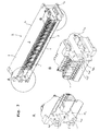
- Fig. 1 is a pictorial view of a heating element 1
and a
tangential blower fan 2 according to the invention. - Fig. 2 is a pictorial view of a heating element 1
and a
tangential blower fan 2 as in Fig. 1 wherein the heating element 1 and thefan 2 are locked relative one another by means of interacting snap lock members 9a1-3, 9a2', 9b1-3, 9b1', 9b3', 14a1-3, 14b1 that are positively engaged with one another. - Fig. 3a-c illustrates the heating element 1, and provides a close-up view of its snap lock members 9a1-3, 9a2', 9b1-3, 9b1', 9b3'.
-
- According to one embodiment of the invention, a heater for an electrical fireplace is provided, which heater comprises a heating element 1 and a
tangential blower fan 2. - The heating element 1 has a
housing 3, within which housing 3 electricallyresistive wires 4 are arranged for heating an air flow passing through the heating element 1. The heating element 1 has anupper part 5, alower part 6, a rear part 7, afront part 8 and two short sides 9a, 9b. The rear part 7 and thefront part 8 are open, in order to provide air inlet and outlet, respectively. - The
tangential blower fan 2 has afan housing 10 and within the housing 10 a fan wheel 11, which in turn is connected via its axle to anelectrical motor 12, which is arranged outside thefan housing 10. Thefan housing 10 has afront part 13 which is plane and rectangular, and whichfront part 13 has an opening working as an air outlet. Thefront part 13 of thefan housing 10 is connectable to the rear part 7 of the heating element 1. In this way, air can flow into the heating element 1 from thefan 2, when the heating element 1 is connected to thefan 2. - Further, on the
fan housing 10 there are twoshort sides 14a, 14b substantially perpendicular to the plane of thefront part 13 of thefan housing 10. The planes of the short sides 9a, 9b of the heating element 1 are parallel with the respective plane of theshort sides 14a,14b of thefan housing 10 when the heating element 1 is connected to thefan 2. - Each short side 9a, 9b of the heating element 1 has a first snap lock member 9a1-3, 9a2', 9b1-3, 9b1', 9b3' that is designed to be positively engaged with corresponding second snap lock member 14a1-3, 14b1 that is arranged on the respective
short side 14a, 14b of thefan housing 10. - In the described embodiment, each short side 9a, 9b of the heating element 1 comprises three pins 9a2', 9b1', 9b3', each pin 9a2', 9b1', 9b3' being arranged to protrude from a flexibly arranged tongue 9a1-3, 9b1-3, which is resilient in a direction substantially perpendicular to the respective short side 9a, 9b of the heating element 1. In one embodiment, the tongues 9a1-3, 9b1-3 are plane parallel with the respective short side 9a, 9b and protrude from the rear part 7 of the heating element 1.
- Each pin 9a2', 9b1', 9b3' is provided with a locking section adapted to interact with a locking surface arranged in a corresponding opening 14a1-3, 14b1 in one of the
short sides 14a, 14b of thefan 2, close to the front edge of theshort side 14a, 14b of thefan 2. - When the heating element 1 is connected to the
fan 2, first and second tongues 9a1, 9a3, 9b1, 9b3 on each short side 9a, 9b of the heating element 1 are located outside the respectiveshort side 14a, 14b of thefan housing 10 with the pins 9b1', 9b3' protruding inward thehousing 10 through the openings 14a1, 14a3, 14b1 in the correspondingshort side 14a, 14b of thefan 2. A third tongue 9a2, 9b2 is located on the inside of thefan housing 10 having its pin 9a2' protruding outward thehousing 10 through a corresponding opening 14a2 in the correspondingshort side 14a, 14b of thefan 2. - Each tongue 9a1-3, 9b1-3 is resilient, which characteristics can be provided by the tongue 9a1-3, 9b1-3 being made from e.g. a thermoplastic material. In the case where the short sides 9a, 9b of the heating element 1 are also made from a thermoplastic material, the tongues 9a1-3, 9b1-3 and the pins 9a2', 9b1', 9b3' may be formed in one piece with the respective short side 9a, 9b, e.g. by injection moulding.
- When the heating element 1 is being connected to the
fan 2, the heating element 1 and thefan 2 are moved towards one another with the rear part 7 of the heating element 1 facing thefront part 13 of thefan 2, whereby the tongue 9a1-3, 9b1-3 and the pins 9a2', 9b1', 9b3' on the heating element 1 are pressed resiliently by the front edges of theshort sides 14a,14b of thefan housing 10 from their normal positions. The first and second pins 9b1', 9b3' are forced in the direction outward from thefan housing 10 and the third pins 9a2' are pressed in the direction towards the inside of thefan housing 10. When the pins 9a2', 9b1', 9b3' match the corresponding openings 14a1-3, 14b1 in theshort sides 14a, 14b of thefan 2, the tongues 9a1-3, 9b1-3 force the pins 9a2', 9b1', 9b3' to spring back towards their normal position and thereby the pins 9a2', 9b1', 9b3' are brought into engagement with the corresponding openings 14a1-3, 14b1 in theshort sides 14a, 14b of thefan 2. Accordingly, the snap lock members 9a1-3, 9a2', 9b1-3, 9b1', 9b3', 14a1-3, 14b1 are positively engaged. - In one embodiment, each pin 9a2', 9b1', 9b3' may be provided with a ramp surface 9a2'', 9b1'', 9b3" for facilitating the engagement of the snap lock, by forcing the respective tongue 9a1-3, 9b1-3 to deflect from its respective normal position.
- In one further embodiment, the
short sides 14a, 14b of thefan 2 may be made wholly or partially resilient, so as to be able to flex during engagement of the snap lock. For example, each opening may be provided on a resilient tongue. Alternatively, the wall of theshort sides 14a, 14b of thefan housing 10 may be slitted on two opposite sides of the opening 14a1-3, 14b1, such that a tongue is provided. - In a second embodiment (not shown), the tongues and pins are provided on the
fan housing 10, whereas the openings are provided on the heating element 1. - In yet another embodiment, one or more tongues and pins are provided on the
fan housing 10 and one or more tongues and pins are provided on the heating element 1, the openings being provided in a corresponding manner on the respective component.
Claims (11)
- A heater for an electrical fireplace, which heater comprises a heating element (1) and a blower fan (2), the blower fan (2) being releasably attached to the heating element (1), characterised in that interacting members (9a1-3, 9a2', 9b1-3, 9b1', 9b3', 14a1-3, 14b1) are provided on the heating element (1) and on the blower fan (2), which members (9a1-3, 9a2', 9b1-3, 9b1', 9b3', 14a1-3, 14b1) are designed to be engaged with one another to hold the heating element (1) in position relative the blower fan (2).
- The heater as claimed in claim 1, wherein the members (9a1-3, 9a2', 9b1-3, 9b1', 9b3', 14a1-3, 14b1) are snap lock members (9a1-3, 9a2', 9b1-3, 9b1', 9b3', 14a1-3, 14b1) that are designed to be positively engaged with one another.
- The heater as claimed in claim 2, wherein the snap lock members (9a1-3, 9a2', 9b1-3, 9b1', 9b3', 14a1-3, 14b1) comprise first and second snap lock members (9a1-3, 9a2', 9b1-3, 9b1', 9b3', 14a1-3, 14b1), the first snap lock member (9a1-3, 9a2', 9b1-3, 9b1', 9b3') having at least one pin (9a2', 9b1', 9b3') designed to be positively engaged with the second snap lock member (14a1-3, 14b1), such that the pin (9a2', 9b1', 9b3') fits in a form fit manner within an opening (14a1-3, 14b1) arranged on the second snap lock member (14a1-3, 14b1).
- The heater as claimed in claim 3, wherein at least one of said snap lock members (9a1-3, 9a2', 9b1-3, 9b1', 9b3', 14a1-3, 14b1) is made from a resilient material.
- The heater as claimed in claim 4, wherein the pin (9a2', 9b1', 9b3') is arranged on a resilient tongue (9a1-3, 9b1-3).
- The heater as claimed in claim 1, wherein the interacting members are designed to be frictionally engaged with one another.
- The heater as claimed in any one of claims 1 to 6, in which the blower fan (2) is a tangential blower fan (2).
- A heating element 1 for use in the heater as claimed in any of claims 1 to 7, characterised in that the heating element (1) comprises a member (9a1-3, 9a2', 9b1-3, 9b1', 9b3') designed to engage with a corresponding member (14a1-3, 14b1) on the blower fan (2), to hold the heating element (1) in position relative the blower fan (2), whereby the heating element (1) is releasably attachable to the blower fan (2).
- The heating element (1) as claimed in claim 8, wherein said member (9a1-3, 9a2', 9b1-3, 9b1', 9b3') on the heating element (1) is a snap lock member (9a1-3, 9a2', 9b1-3, 9b1', 9b3') adapted to be positively engaged with a corresponding member (14a1-3, 14b1) on said blower fan (2).
- A blower fan (2) for use in a heater as claimed in any of claims 1 to 7, characterised in that the blower fan (2) comprises a member (14a1-3, 14b1) designed to engage with a corresponding member (9a1-3, 9a2', 9b1-3, 9b1', 9b3') on the heating element (1) to hold the blower fan (2) in position relative the heating element (1), whereby the blower fan (2) is releasably attachable to the heating element (1).
- The blower fan (2) as claimed in claim 10, wherein said member (14a1-3, 14b1) on the blower fan (2) is a snap lock member (14a1-3, 14b1) adapted to be positively engaged with a corresponding member (9a1-3, 9a2', 9b1-3, 9b1', 9b3') on said heating element (1).
Priority Applications (5)
| Application Number | Priority Date | Filing Date | Title |
|---|---|---|---|
| AT04004971T ATE362081T1 (en) | 2004-03-03 | 2004-03-03 | A HEATER, A HEATING ELEMENT AND A FAN |
| EP04004971A EP1571397B1 (en) | 2004-03-03 | 2004-03-03 | A heater, a heating element and a blower fan |
| DE602004006371T DE602004006371T2 (en) | 2004-03-03 | 2004-03-03 | A heater, a heating element and a fan |
| US10/591,656 US7894712B2 (en) | 2004-03-03 | 2005-03-02 | Heater, a heating element and a blower fan |
| PCT/SE2005/000310 WO2005085713A1 (en) | 2004-03-03 | 2005-03-02 | A heater, a heating element and a blower fan |
Applications Claiming Priority (1)
| Application Number | Priority Date | Filing Date | Title |
|---|---|---|---|
| EP04004971A EP1571397B1 (en) | 2004-03-03 | 2004-03-03 | A heater, a heating element and a blower fan |
Publications (2)
| Publication Number | Publication Date |
|---|---|
| EP1571397A1 true EP1571397A1 (en) | 2005-09-07 |
| EP1571397B1 EP1571397B1 (en) | 2007-05-09 |
Family
ID=34745993
Family Applications (1)
| Application Number | Title | Priority Date | Filing Date |
|---|---|---|---|
| EP04004971A Expired - Lifetime EP1571397B1 (en) | 2004-03-03 | 2004-03-03 | A heater, a heating element and a blower fan |
Country Status (5)
| Country | Link |
|---|---|
| US (1) | US7894712B2 (en) |
| EP (1) | EP1571397B1 (en) |
| AT (1) | ATE362081T1 (en) |
| DE (1) | DE602004006371T2 (en) |
| WO (1) | WO2005085713A1 (en) |
Families Citing this family (4)
| Publication number | Priority date | Publication date | Assignee | Title |
|---|---|---|---|---|
| WO2014135396A1 (en) | 2013-03-08 | 2014-09-12 | Fergas Ab | Fan unit |
| US9447981B2 (en) * | 2013-12-06 | 2016-09-20 | Perfect Union Co., Ltd. | Cooling fan having detachable heater |
| US20210372627A1 (en) * | 2020-05-29 | 2021-12-02 | Twin-Star International, Inc. | Modular fireplace insert |
| USD1112663S1 (en) * | 2024-07-26 | 2026-02-10 | Min-Hsun Lu | Heater for electric fireplace |
Citations (11)
| Publication number | Priority date | Publication date | Assignee | Title |
|---|---|---|---|---|
| US2015251A (en) * | 1934-03-12 | 1935-09-24 | Chicago Flexible Shaft Co | Space heater |
| US2986622A (en) * | 1959-12-24 | 1961-05-30 | Roy W Brazda | Portable heater for trucks and the like |
| DE1212703B (en) * | 1959-06-06 | 1966-03-17 | Braun Ag | Movable room fan |
| US3742189A (en) * | 1971-09-20 | 1973-06-26 | Meyer F Of California | Simulated fireplace assembly |
| US4703153A (en) * | 1985-06-24 | 1987-10-27 | Pelko Electric Inc. | Electric heater employing semiconductor heating elements |
| US4737616A (en) * | 1986-05-12 | 1988-04-12 | Wen Ying Lee | Multi-function portable electric room heater having a removable heating cartridge |
| US4809593A (en) * | 1986-07-09 | 1989-03-07 | Suncourt Holdings Inc. | Portable fan device for forced air heating |
| DE3908512A1 (en) * | 1988-03-15 | 1989-09-28 | Maico Elektroapparate | Fan |
| GB2251935A (en) * | 1990-12-21 | 1992-07-22 | Basic Engineering | Radiant and convected air heating apparatus |
| US5443364A (en) * | 1993-10-18 | 1995-08-22 | Carrier Corporation | Snap-fit inducer housing and cover for gas furnace |
| US5513296A (en) * | 1994-06-08 | 1996-04-30 | Holmes Products Corp. | Air heater with angled PTC heaters producing diverging heated airflow |
Family Cites Families (8)
| Publication number | Priority date | Publication date | Assignee | Title |
|---|---|---|---|---|
| US2655587A (en) * | 1951-05-11 | 1953-10-13 | Steingruber Minnie Baas | Wall-mountable electric heater and housing assembly therefor |
| GB996056A (en) * | 1961-06-20 | 1965-06-23 | Philips Electronic Associated | Blower |
| FR1501517A (en) * | 1966-03-25 | 1967-11-10 | Siemens Elektrogeraete Gmbh | Electric household appliance |
| GB2089626B (en) * | 1980-12-11 | 1984-06-20 | Standard Telephones Cables Ltd | Electric resistance heating element |
| GB8332286D0 (en) | 1983-12-02 | 1984-01-11 | Valor Heating Ltd | Domestic heating appliance |
| US5256857A (en) * | 1990-08-22 | 1993-10-26 | Texas Instruments Incorporated | Finned PTC air heater assembly for heating an automotive passenger compartment |
| GB2309900B (en) * | 1994-11-17 | 1998-03-25 | Mcdougall Gregory J | Electric fan heater |
| GB0505280D0 (en) * | 2005-03-16 | 2005-04-20 | Chung Mei Ind Ltd | Low noise fan heater |
-
2004
- 2004-03-03 EP EP04004971A patent/EP1571397B1/en not_active Expired - Lifetime
- 2004-03-03 AT AT04004971T patent/ATE362081T1/en not_active IP Right Cessation
- 2004-03-03 DE DE602004006371T patent/DE602004006371T2/en not_active Expired - Lifetime
-
2005
- 2005-03-02 US US10/591,656 patent/US7894712B2/en active Active
- 2005-03-02 WO PCT/SE2005/000310 patent/WO2005085713A1/en not_active Ceased
Patent Citations (11)
| Publication number | Priority date | Publication date | Assignee | Title |
|---|---|---|---|---|
| US2015251A (en) * | 1934-03-12 | 1935-09-24 | Chicago Flexible Shaft Co | Space heater |
| DE1212703B (en) * | 1959-06-06 | 1966-03-17 | Braun Ag | Movable room fan |
| US2986622A (en) * | 1959-12-24 | 1961-05-30 | Roy W Brazda | Portable heater for trucks and the like |
| US3742189A (en) * | 1971-09-20 | 1973-06-26 | Meyer F Of California | Simulated fireplace assembly |
| US4703153A (en) * | 1985-06-24 | 1987-10-27 | Pelko Electric Inc. | Electric heater employing semiconductor heating elements |
| US4737616A (en) * | 1986-05-12 | 1988-04-12 | Wen Ying Lee | Multi-function portable electric room heater having a removable heating cartridge |
| US4809593A (en) * | 1986-07-09 | 1989-03-07 | Suncourt Holdings Inc. | Portable fan device for forced air heating |
| DE3908512A1 (en) * | 1988-03-15 | 1989-09-28 | Maico Elektroapparate | Fan |
| GB2251935A (en) * | 1990-12-21 | 1992-07-22 | Basic Engineering | Radiant and convected air heating apparatus |
| US5443364A (en) * | 1993-10-18 | 1995-08-22 | Carrier Corporation | Snap-fit inducer housing and cover for gas furnace |
| US5513296A (en) * | 1994-06-08 | 1996-04-30 | Holmes Products Corp. | Air heater with angled PTC heaters producing diverging heated airflow |
Also Published As
| Publication number | Publication date |
|---|---|
| DE602004006371D1 (en) | 2007-06-21 |
| US20080037963A1 (en) | 2008-02-14 |
| US7894712B2 (en) | 2011-02-22 |
| DE602004006371T2 (en) | 2008-01-10 |
| EP1571397B1 (en) | 2007-05-09 |
| ATE362081T1 (en) | 2007-06-15 |
| WO2005085713A1 (en) | 2005-09-15 |
Similar Documents
| Publication | Publication Date | Title |
|---|---|---|
| US8718454B2 (en) | Module for manufacturing electric volatile substance evaporators | |
| EP1571397B1 (en) | A heater, a heating element and a blower fan | |
| WO2018100654A1 (en) | Air conditioner indoor unit | |
| JP3750298B2 (en) | Recessed ceiling air conditioner | |
| KR200161129Y1 (en) | Display assembly structure of air conditioner | |
| CN108645000B (en) | Cover plate, indoor unit and air conditioner | |
| CN215336700U (en) | Air duct machine and air conditioner | |
| CN219713467U (en) | Warmer | |
| KR20240072718A (en) | Control box assembly and electronic device including thereof | |
| CN210292098U (en) | An air purification module installation structure and air conditioner | |
| CN100371611C (en) | Hot-plug fan module and plug-in part thereof | |
| CN215260126U (en) | Air conditioner | |
| KR102207058B1 (en) | DIY Air Cleaner | |
| CN108036413B (en) | Air conditioner indoor unit and air conditioner | |
| CN223938297U (en) | An easy-to-assemble fan | |
| CN213395617U (en) | Air inlet assembly and ceiling machine | |
| KR102602210B1 (en) | Ventilator cover structur | |
| CN211822773U (en) | Wall-mounted air conditioner indoor unit | |
| KR900005390Y1 (en) | Combining apparatus for grill in airconditioner | |
| KR102564524B1 (en) | fan heater | |
| CN213342925U (en) | Cover and covering system comprising same | |
| JP4158488B2 (en) | Bathroom ventilator | |
| CN219713455U (en) | Heating module | |
| CN209877167U (en) | Dust filter assembly and air conditioner indoor unit with same | |
| CN117366064A (en) | Panel structure and household appliances |
Legal Events
| Date | Code | Title | Description |
|---|---|---|---|
| PUAI | Public reference made under article 153(3) epc to a published international application that has entered the european phase |
Free format text: ORIGINAL CODE: 0009012 |
|
| AK | Designated contracting states |
Kind code of ref document: A1 Designated state(s): AT BE BG CH CY CZ DE DK EE ES FI FR GB GR HU IE IT LI LU MC NL PL PT RO SE SI SK TR |
|
| AX | Request for extension of the european patent |
Extension state: AL LT LV MK |
|
| 17P | Request for examination filed |
Effective date: 20051028 |
|
| AKX | Designation fees paid |
Designated state(s): AT BE BG CH CY CZ DE DK EE ES FI FR GB GR HU IE IT LI LU MC NL PL PT RO SE SI SK TR |
|
| GRAP | Despatch of communication of intention to grant a patent |
Free format text: ORIGINAL CODE: EPIDOSNIGR1 |
|
| GRAS | Grant fee paid |
Free format text: ORIGINAL CODE: EPIDOSNIGR3 |
|
| GRAA | (expected) grant |
Free format text: ORIGINAL CODE: 0009210 |
|
| AK | Designated contracting states |
Kind code of ref document: B1 Designated state(s): AT BE BG CH CY CZ DE DK EE ES FI FR GB GR HU IE IT LI LU MC NL PL PT RO SE SI SK TR |
|
| PG25 | Lapsed in a contracting state [announced via postgrant information from national office to epo] |
Ref country code: FI Free format text: LAPSE BECAUSE OF FAILURE TO SUBMIT A TRANSLATION OF THE DESCRIPTION OR TO PAY THE FEE WITHIN THE PRESCRIBED TIME-LIMIT Effective date: 20070509 Ref country code: LI Free format text: LAPSE BECAUSE OF FAILURE TO SUBMIT A TRANSLATION OF THE DESCRIPTION OR TO PAY THE FEE WITHIN THE PRESCRIBED TIME-LIMIT Effective date: 20070509 Ref country code: CH Free format text: LAPSE BECAUSE OF FAILURE TO SUBMIT A TRANSLATION OF THE DESCRIPTION OR TO PAY THE FEE WITHIN THE PRESCRIBED TIME-LIMIT Effective date: 20070509 |
|
| REG | Reference to a national code |
Ref country code: GB Ref legal event code: FG4D |
|
| REG | Reference to a national code |
Ref country code: CH Ref legal event code: EP |
|
| REG | Reference to a national code |
Ref country code: IE Ref legal event code: FG4D |
|
| REF | Corresponds to: |
Ref document number: 602004006371 Country of ref document: DE Date of ref document: 20070621 Kind code of ref document: P |
|
| PG25 | Lapsed in a contracting state [announced via postgrant information from national office to epo] |
Ref country code: SE Free format text: LAPSE BECAUSE OF FAILURE TO SUBMIT A TRANSLATION OF THE DESCRIPTION OR TO PAY THE FEE WITHIN THE PRESCRIBED TIME-LIMIT Effective date: 20070809 |
|
| PG25 | Lapsed in a contracting state [announced via postgrant information from national office to epo] |
Ref country code: ES Free format text: LAPSE BECAUSE OF FAILURE TO SUBMIT A TRANSLATION OF THE DESCRIPTION OR TO PAY THE FEE WITHIN THE PRESCRIBED TIME-LIMIT Effective date: 20070820 |
|
| NLV1 | Nl: lapsed or annulled due to failure to fulfill the requirements of art. 29p and 29m of the patents act | ||
| ET | Fr: translation filed | ||
| REG | Reference to a national code |
Ref country code: CH Ref legal event code: PL |
|
| PG25 | Lapsed in a contracting state [announced via postgrant information from national office to epo] |
Ref country code: PL Free format text: LAPSE BECAUSE OF FAILURE TO SUBMIT A TRANSLATION OF THE DESCRIPTION OR TO PAY THE FEE WITHIN THE PRESCRIBED TIME-LIMIT Effective date: 20070509 Ref country code: AT Free format text: LAPSE BECAUSE OF FAILURE TO SUBMIT A TRANSLATION OF THE DESCRIPTION OR TO PAY THE FEE WITHIN THE PRESCRIBED TIME-LIMIT Effective date: 20070509 |
|
| PG25 | Lapsed in a contracting state [announced via postgrant information from national office to epo] |
Ref country code: BE Free format text: LAPSE BECAUSE OF FAILURE TO SUBMIT A TRANSLATION OF THE DESCRIPTION OR TO PAY THE FEE WITHIN THE PRESCRIBED TIME-LIMIT Effective date: 20070509 |
|
| PG25 | Lapsed in a contracting state [announced via postgrant information from national office to epo] |
Ref country code: PT Free format text: LAPSE BECAUSE OF FAILURE TO SUBMIT A TRANSLATION OF THE DESCRIPTION OR TO PAY THE FEE WITHIN THE PRESCRIBED TIME-LIMIT Effective date: 20071009 Ref country code: CZ Free format text: LAPSE BECAUSE OF FAILURE TO SUBMIT A TRANSLATION OF THE DESCRIPTION OR TO PAY THE FEE WITHIN THE PRESCRIBED TIME-LIMIT Effective date: 20070509 Ref country code: BG Free format text: LAPSE BECAUSE OF FAILURE TO SUBMIT A TRANSLATION OF THE DESCRIPTION OR TO PAY THE FEE WITHIN THE PRESCRIBED TIME-LIMIT Effective date: 20070809 Ref country code: SI Free format text: LAPSE BECAUSE OF FAILURE TO SUBMIT A TRANSLATION OF THE DESCRIPTION OR TO PAY THE FEE WITHIN THE PRESCRIBED TIME-LIMIT Effective date: 20070509 Ref country code: NL Free format text: LAPSE BECAUSE OF FAILURE TO SUBMIT A TRANSLATION OF THE DESCRIPTION OR TO PAY THE FEE WITHIN THE PRESCRIBED TIME-LIMIT Effective date: 20070509 Ref country code: DK Free format text: LAPSE BECAUSE OF FAILURE TO SUBMIT A TRANSLATION OF THE DESCRIPTION OR TO PAY THE FEE WITHIN THE PRESCRIBED TIME-LIMIT Effective date: 20070509 |
|
| PG25 | Lapsed in a contracting state [announced via postgrant information from national office to epo] |
Ref country code: SK Free format text: LAPSE BECAUSE OF FAILURE TO SUBMIT A TRANSLATION OF THE DESCRIPTION OR TO PAY THE FEE WITHIN THE PRESCRIBED TIME-LIMIT Effective date: 20070509 |
|
| PLBE | No opposition filed within time limit |
Free format text: ORIGINAL CODE: 0009261 |
|
| STAA | Information on the status of an ep patent application or granted ep patent |
Free format text: STATUS: NO OPPOSITION FILED WITHIN TIME LIMIT |
|
| 26N | No opposition filed |
Effective date: 20080212 |
|
| PG25 | Lapsed in a contracting state [announced via postgrant information from national office to epo] |
Ref country code: IT Free format text: LAPSE BECAUSE OF FAILURE TO SUBMIT A TRANSLATION OF THE DESCRIPTION OR TO PAY THE FEE WITHIN THE PRESCRIBED TIME-LIMIT Effective date: 20070509 Ref country code: GR Free format text: LAPSE BECAUSE OF FAILURE TO SUBMIT A TRANSLATION OF THE DESCRIPTION OR TO PAY THE FEE WITHIN THE PRESCRIBED TIME-LIMIT Effective date: 20070810 |
|
| PG25 | Lapsed in a contracting state [announced via postgrant information from national office to epo] |
Ref country code: RO Free format text: LAPSE BECAUSE OF FAILURE TO SUBMIT A TRANSLATION OF THE DESCRIPTION OR TO PAY THE FEE WITHIN THE PRESCRIBED TIME-LIMIT Effective date: 20070509 |
|
| PG25 | Lapsed in a contracting state [announced via postgrant information from national office to epo] |
Ref country code: MC Free format text: LAPSE BECAUSE OF NON-PAYMENT OF DUE FEES Effective date: 20080331 |
|
| PG25 | Lapsed in a contracting state [announced via postgrant information from national office to epo] |
Ref country code: EE Free format text: LAPSE BECAUSE OF FAILURE TO SUBMIT A TRANSLATION OF THE DESCRIPTION OR TO PAY THE FEE WITHIN THE PRESCRIBED TIME-LIMIT Effective date: 20070509 Ref country code: IE Free format text: LAPSE BECAUSE OF NON-PAYMENT OF DUE FEES Effective date: 20080303 |
|
| PG25 | Lapsed in a contracting state [announced via postgrant information from national office to epo] |
Ref country code: CY Free format text: LAPSE BECAUSE OF FAILURE TO SUBMIT A TRANSLATION OF THE DESCRIPTION OR TO PAY THE FEE WITHIN THE PRESCRIBED TIME-LIMIT Effective date: 20070509 |
|
| PG25 | Lapsed in a contracting state [announced via postgrant information from national office to epo] |
Ref country code: LU Free format text: LAPSE BECAUSE OF NON-PAYMENT OF DUE FEES Effective date: 20080303 Ref country code: HU Free format text: LAPSE BECAUSE OF FAILURE TO SUBMIT A TRANSLATION OF THE DESCRIPTION OR TO PAY THE FEE WITHIN THE PRESCRIBED TIME-LIMIT Effective date: 20071110 |
|
| PG25 | Lapsed in a contracting state [announced via postgrant information from national office to epo] |
Ref country code: TR Free format text: LAPSE BECAUSE OF FAILURE TO SUBMIT A TRANSLATION OF THE DESCRIPTION OR TO PAY THE FEE WITHIN THE PRESCRIBED TIME-LIMIT Effective date: 20070509 |
|
| REG | Reference to a national code |
Ref country code: FR Ref legal event code: PLFP Year of fee payment: 12 |
|
| REG | Reference to a national code |
Ref country code: FR Ref legal event code: PLFP Year of fee payment: 13 |
|
| REG | Reference to a national code |
Ref country code: FR Ref legal event code: PLFP Year of fee payment: 14 |
|
| REG | Reference to a national code |
Ref country code: FR Ref legal event code: PLFP Year of fee payment: 15 |
|
| REG | Reference to a national code |
Ref country code: DE Ref legal event code: R082 Ref document number: 602004006371 Country of ref document: DE Representative=s name: MAIWALD GMBH, DE Ref country code: DE Ref legal event code: R082 Ref document number: 602004006371 Country of ref document: DE Representative=s name: MAIWALD PATENTANWALTS- UND RECHTSANWALTSGESELL, DE |
|
| PGFP | Annual fee paid to national office [announced via postgrant information from national office to epo] |
Ref country code: GB Payment date: 20220429 Year of fee payment: 19 Ref country code: FR Payment date: 20220429 Year of fee payment: 19 Ref country code: DE Payment date: 20220520 Year of fee payment: 19 |
|
| REG | Reference to a national code |
Ref country code: DE Ref legal event code: R119 Ref document number: 602004006371 Country of ref document: DE |
|
| GBPC | Gb: european patent ceased through non-payment of renewal fee |
Effective date: 20230303 |
|
| PG25 | Lapsed in a contracting state [announced via postgrant information from national office to epo] |
Ref country code: GB Free format text: LAPSE BECAUSE OF NON-PAYMENT OF DUE FEES Effective date: 20230303 |
|
| PG25 | Lapsed in a contracting state [announced via postgrant information from national office to epo] |
Ref country code: GB Free format text: LAPSE BECAUSE OF NON-PAYMENT OF DUE FEES Effective date: 20230303 Ref country code: FR Free format text: LAPSE BECAUSE OF NON-PAYMENT OF DUE FEES Effective date: 20230331 Ref country code: DE Free format text: LAPSE BECAUSE OF NON-PAYMENT OF DUE FEES Effective date: 20231003 |