EP1571322A2 - Diesel engine - Google Patents
Diesel engine Download PDFInfo
- Publication number
- EP1571322A2 EP1571322A2 EP05004149A EP05004149A EP1571322A2 EP 1571322 A2 EP1571322 A2 EP 1571322A2 EP 05004149 A EP05004149 A EP 05004149A EP 05004149 A EP05004149 A EP 05004149A EP 1571322 A2 EP1571322 A2 EP 1571322A2
- Authority
- EP
- European Patent Office
- Prior art keywords
- intake air
- air quantity
- target
- egr
- valve
- Prior art date
- Legal status (The legal status is an assumption and is not a legal conclusion. Google has not performed a legal analysis and makes no representation as to the accuracy of the status listed.)
- Granted
Links
Images


Classifications
-
- F—MECHANICAL ENGINEERING; LIGHTING; HEATING; WEAPONS; BLASTING
- F02—COMBUSTION ENGINES; HOT-GAS OR COMBUSTION-PRODUCT ENGINE PLANTS
- F02D—CONTROLLING COMBUSTION ENGINES
- F02D41/00—Electrical control of supply of combustible mixture or its constituents
- F02D41/0025—Controlling engines characterised by use of non-liquid fuels, pluralities of fuels, or non-fuel substances added to the combustible mixtures
- F02D41/0047—Controlling exhaust gas recirculation [EGR]
- F02D41/005—Controlling exhaust gas recirculation [EGR] according to engine operating conditions
- F02D41/0052—Feedback control of engine parameters, e.g. for control of air/fuel ratio or intake air amount
-
- F—MECHANICAL ENGINEERING; LIGHTING; HEATING; WEAPONS; BLASTING
- F02—COMBUSTION ENGINES; HOT-GAS OR COMBUSTION-PRODUCT ENGINE PLANTS
- F02D—CONTROLLING COMBUSTION ENGINES
- F02D41/00—Electrical control of supply of combustible mixture or its constituents
- F02D41/0002—Controlling intake air
-
- F—MECHANICAL ENGINEERING; LIGHTING; HEATING; WEAPONS; BLASTING
- F02—COMBUSTION ENGINES; HOT-GAS OR COMBUSTION-PRODUCT ENGINE PLANTS
- F02D—CONTROLLING COMBUSTION ENGINES
- F02D41/00—Electrical control of supply of combustible mixture or its constituents
- F02D41/02—Circuit arrangements for generating control signals
- F02D41/18—Circuit arrangements for generating control signals by measuring intake air flow
-
- F—MECHANICAL ENGINEERING; LIGHTING; HEATING; WEAPONS; BLASTING
- F02—COMBUSTION ENGINES; HOT-GAS OR COMBUSTION-PRODUCT ENGINE PLANTS
- F02D—CONTROLLING COMBUSTION ENGINES
- F02D41/00—Electrical control of supply of combustible mixture or its constituents
- F02D41/30—Controlling fuel injection
- F02D41/3011—Controlling fuel injection according to or using specific or several modes of combustion
- F02D41/3017—Controlling fuel injection according to or using specific or several modes of combustion characterised by the mode(s) being used
- F02D41/3035—Controlling fuel injection according to or using specific or several modes of combustion characterised by the mode(s) being used a mode being the premixed charge compression-ignition mode
-
- F—MECHANICAL ENGINEERING; LIGHTING; HEATING; WEAPONS; BLASTING
- F02—COMBUSTION ENGINES; HOT-GAS OR COMBUSTION-PRODUCT ENGINE PLANTS
- F02M—SUPPLYING COMBUSTION ENGINES IN GENERAL WITH COMBUSTIBLE MIXTURES OR CONSTITUENTS THEREOF
- F02M26/00—Engine-pertinent apparatus for adding exhaust gases to combustion-air, main fuel or fuel-air mixture, e.g. by exhaust gas recirculation [EGR] systems
- F02M26/45—Sensors specially adapted for EGR systems
- F02M26/46—Sensors specially adapted for EGR systems for determining the characteristics of gases, e.g. composition
- F02M26/47—Sensors specially adapted for EGR systems for determining the characteristics of gases, e.g. composition the characteristics being temperatures, pressures or flow rates
-
- F—MECHANICAL ENGINEERING; LIGHTING; HEATING; WEAPONS; BLASTING
- F02—COMBUSTION ENGINES; HOT-GAS OR COMBUSTION-PRODUCT ENGINE PLANTS
- F02B—INTERNAL-COMBUSTION PISTON ENGINES; COMBUSTION ENGINES IN GENERAL
- F02B29/00—Engines characterised by provision for charging or scavenging not provided for in groups F02B25/00, F02B27/00 or F02B33/00 - F02B39/00; Details thereof
- F02B29/04—Cooling of air intake supply
- F02B29/0406—Layout of the intake air cooling or coolant circuit
-
- F—MECHANICAL ENGINEERING; LIGHTING; HEATING; WEAPONS; BLASTING
- F02—COMBUSTION ENGINES; HOT-GAS OR COMBUSTION-PRODUCT ENGINE PLANTS
- F02D—CONTROLLING COMBUSTION ENGINES
- F02D41/00—Electrical control of supply of combustible mixture or its constituents
- F02D41/0002—Controlling intake air
- F02D2041/0017—Controlling intake air by simultaneous control of throttle and exhaust gas recirculation
-
- F—MECHANICAL ENGINEERING; LIGHTING; HEATING; WEAPONS; BLASTING
- F02—COMBUSTION ENGINES; HOT-GAS OR COMBUSTION-PRODUCT ENGINE PLANTS
- F02D—CONTROLLING COMBUSTION ENGINES
- F02D41/00—Electrical control of supply of combustible mixture or its constituents
- F02D41/0002—Controlling intake air
- F02D2041/0022—Controlling intake air for diesel engines by throttle control
-
- F—MECHANICAL ENGINEERING; LIGHTING; HEATING; WEAPONS; BLASTING
- F02—COMBUSTION ENGINES; HOT-GAS OR COMBUSTION-PRODUCT ENGINE PLANTS
- F02D—CONTROLLING COMBUSTION ENGINES
- F02D41/00—Electrical control of supply of combustible mixture or its constituents
- F02D41/0002—Controlling intake air
- F02D41/0007—Controlling intake air for control of turbo-charged or super-charged engines
-
- F—MECHANICAL ENGINEERING; LIGHTING; HEATING; WEAPONS; BLASTING
- F02—COMBUSTION ENGINES; HOT-GAS OR COMBUSTION-PRODUCT ENGINE PLANTS
- F02M—SUPPLYING COMBUSTION ENGINES IN GENERAL WITH COMBUSTIBLE MIXTURES OR CONSTITUENTS THEREOF
- F02M26/00—Engine-pertinent apparatus for adding exhaust gases to combustion-air, main fuel or fuel-air mixture, e.g. by exhaust gas recirculation [EGR] systems
- F02M26/02—EGR systems specially adapted for supercharged engines
- F02M26/04—EGR systems specially adapted for supercharged engines with a single turbocharger
- F02M26/05—High pressure loops, i.e. wherein recirculated exhaust gas is taken out from the exhaust system upstream of the turbine and reintroduced into the intake system downstream of the compressor
-
- F—MECHANICAL ENGINEERING; LIGHTING; HEATING; WEAPONS; BLASTING
- F02—COMBUSTION ENGINES; HOT-GAS OR COMBUSTION-PRODUCT ENGINE PLANTS
- F02M—SUPPLYING COMBUSTION ENGINES IN GENERAL WITH COMBUSTIBLE MIXTURES OR CONSTITUENTS THEREOF
- F02M26/00—Engine-pertinent apparatus for adding exhaust gases to combustion-air, main fuel or fuel-air mixture, e.g. by exhaust gas recirculation [EGR] systems
- F02M26/13—Arrangement or layout of EGR passages, e.g. in relation to specific engine parts or for incorporation of accessories
- F02M26/22—Arrangement or layout of EGR passages, e.g. in relation to specific engine parts or for incorporation of accessories with coolers in the recirculation passage
- F02M26/23—Layout, e.g. schematics
-
- F—MECHANICAL ENGINEERING; LIGHTING; HEATING; WEAPONS; BLASTING
- F02—COMBUSTION ENGINES; HOT-GAS OR COMBUSTION-PRODUCT ENGINE PLANTS
- F02M—SUPPLYING COMBUSTION ENGINES IN GENERAL WITH COMBUSTIBLE MIXTURES OR CONSTITUENTS THEREOF
- F02M26/00—Engine-pertinent apparatus for adding exhaust gases to combustion-air, main fuel or fuel-air mixture, e.g. by exhaust gas recirculation [EGR] systems
- F02M26/45—Sensors specially adapted for EGR systems
- F02M26/46—Sensors specially adapted for EGR systems for determining the characteristics of gases, e.g. composition
-
- F—MECHANICAL ENGINEERING; LIGHTING; HEATING; WEAPONS; BLASTING
- F02—COMBUSTION ENGINES; HOT-GAS OR COMBUSTION-PRODUCT ENGINE PLANTS
- F02M—SUPPLYING COMBUSTION ENGINES IN GENERAL WITH COMBUSTIBLE MIXTURES OR CONSTITUENTS THEREOF
- F02M26/00—Engine-pertinent apparatus for adding exhaust gases to combustion-air, main fuel or fuel-air mixture, e.g. by exhaust gas recirculation [EGR] systems
- F02M26/45—Sensors specially adapted for EGR systems
- F02M26/48—EGR valve position sensors
-
- Y—GENERAL TAGGING OF NEW TECHNOLOGICAL DEVELOPMENTS; GENERAL TAGGING OF CROSS-SECTIONAL TECHNOLOGIES SPANNING OVER SEVERAL SECTIONS OF THE IPC; TECHNICAL SUBJECTS COVERED BY FORMER USPC CROSS-REFERENCE ART COLLECTIONS [XRACs] AND DIGESTS
- Y02—TECHNOLOGIES OR APPLICATIONS FOR MITIGATION OR ADAPTATION AGAINST CLIMATE CHANGE
- Y02T—CLIMATE CHANGE MITIGATION TECHNOLOGIES RELATED TO TRANSPORTATION
- Y02T10/00—Road transport of goods or passengers
- Y02T10/10—Internal combustion engine [ICE] based vehicles
- Y02T10/40—Engine management systems
Definitions
- the present invention relates to a diesel engine in which premix combustion is implemented, and more particularly to a diesel engine with optimized fuel ignition timing in the premix combustion.
- fuel In diesel engines, fuel is typically injected close to a compression top dead center of the piston when the temperature and pressure inside the cylinder are high.
- the injected fuel is mixed with the intake air, forming a mixture, this mixture is ignited producing a flame, and the combustion is maintained by supplying subsequently injected fuel into this flame. In other words, ignition starts during fuel injection.
- premix combustion a combustion system called "premix combustion” in which the fuel injection timing is set earlier than the compression top dead center has recently been suggested (for example, see Japanese Patent Applications Laid-open Nos. 2001-20784 and 2002-327638).
- the premix combustion the combustion is started due to initiation of thermal decomposition or oxidation reaction of the fuel accompanying the increase in temperature inside the cylinder in the course of the compression cycle after the end of fuel injection.
- the compression self-ignition proceeds once a certain interval elapses after the end of fuel injection.
- the mixture is sufficiently leaned and homogenized. Therefore, local combustion temperature decreases and the amount of released NOx(nitrogen oxide) is decreased.
- the emission of smoke is also inhibited because local combustion is in an air shortage state.
- the premix combustion was thus effective for improving the exhaust gas, but the problem associated therewith was that the fuel ignition timing was difficult to control.
- the ignition timing can be controlled by controlling the fuel injection timing, but in the premix combustion there is a premixing interval (interval from the end of fuel injection to ignition). Therefore, the ignition timing cannot be fully and stringently controlled by controlling the fuel injection timing.
- Japanese Patent Application Laid-open 2002-327638 described a diesel engine comprising a variable supercharger with an adjustable boot pressure and an EGR unit, wherein the target intake air quantity necessary to ignite the fuel at the optimum timing is set for each engine operation state, and the boost pressure and EGR ratio are adjusted so that the actual intake air quantity becomes the target intake air quantity.
- the EGR (exhaust gas recirculation) ratio and intake air quantity change if the boost pressure is changed, it is necessary to control the boost pressure in cooperation with the EGR ratio.
- the intake air quantity is not easy to control to a target value because changes in the intake air quantity caused by changes in the boost pressure and changes in the intake air quantity caused by changes in the EGR ratio are intertwined in a complex manner.
- the present invention provides a diesel engine comprising an EGR valve, an intake throttle valve provided upstream of an EGR gas inlet portion in an intake channel, control means for controlling those EGR valve and intake throttle valve, and intake air quantity detection means for detecting the intake air quantity upstream of an EGR gas inlet portion in the intake channel, this diesel engine implementing a premix combustion in which a fuel is injected earlier than the compression top dead center at least in the prescribed operation region and the compressed self ignition is performed after the injection is completed, wherein the control means, at least in the operation region in which the premix combustion is implemented, determines a target intake air quantity necessary for igniting the fuel at the target timing based on an engine operation state and controls the intake throttle valve and/or EGR valve so that the actual intake air quantity detected by the intake air quantity detection means matches the target intake air quantity.
- the target values of at least any one of the quantity of oxygen, oxygen concentration, air/fuel ratio, EGR ratio, and inert gas concentration necessary for the fuel to be ignited at the optimum timing, or a combination of two or more thereof, or other physical parameters corresponding thereto may be determined for each engine operation state, and the target intake air quantity may be determined such that at least any one of the quantity of oxygen, oxygen concentration, air/fuel ratio, EGR ratio, and inert gas concentration, or a combination of two or more thereof, or other physical parameters corresponding thereto match the target values.
- control means may fix the opening degree of the EGR valve and control the opening and closing of only the intake throttle valve when the target intake air quantity is equal to or less than a first set value.
- the control means may control the opening of both the EGR valve and the intake throttle valve when the target intake air quantity is larger than the first set value and equal to or less than a second set value.
- the control means may fix the opening degree of the intake throttle valve and control the opening of only the EGR valve when the target intake air quantity is larger than the second set value.
- control means may fix the opening degree of the EGR valve to a full open state and control the opening of only the intake throttle valve when the target intake air quantity is equal to or less than the first set value.
- the control means may fix the opening degree of the intake throttle valve to a full open state and control the opening of only the EGR valve when the target intake air quantity is larger than the second set value.
- the diesel engine may further comprise a variable supercharger equipped with boost pressure adjustment means, wherein the control means may control the boost pressure adjustment means according to a map that was set in advance, irrespectively of the target intake air quantity.
- control means may make a control amount of the boost pressure adjustment means constant in the operation region where the premix combustion is implemented.
- the boost pressure adjustment means may comprise a boost pressure adjustment valve for changing the flow rate of exhaust gases introduced into an exhaust turbine provided in an exhaust channel, and the control means may fix the boost pressure adjustment valve to a fully closed state in the operation region where the premix combustion is implemented.
- a control method for a diesel engine comprising an EGR valve, an intake throttle valve provided upstream of an EGR gas inlet portion in an intake channel, control means for controlling those EGR valve and intake throttle valve, and intake air quantity detection means for detecting the intake air quantity upstream of an EGR gas inlet portion in the intake channel, this diesel engine implementing a premix combustion in which a fuel is injected earlier than the compression top dead center at least in the prescribed operation region and the compressed self ignition is performed after the injection is completed, the method comprising the steps of determining a target intake air quantity necessary for igniting the fuel at the target timing based on an engine operation state, and controlling the intake throttle valve and/or EGR valve so that the actual intake air quantity detected by the intake air quantity detection means matches the target intake air quantity.
- a diesel engine comprising an EGR valve, an intake throttle valve provided upstream of an EGR gas inlet portion in an intake channel, control means for controlling those EGR valve and intake throttle valve, and oxygen quantity detection means for detecting the oxygen quantity in the gas mixture, this diesel engine implementing a premix combustion in which a fuel is injected earlier than the compression top dead center at least in the prescribed operation region and the compressed self ignition is performed after the injection is completed, wherein the control means, at least in the operation region in which the premix combustion is implemented, determines a target oxygen quantity necessary for igniting the fuel at the target timing based on an engine operation state and controls the intake throttle valve and/or EGR valve so that the actual oxygen quantity detected by the oxygen quantity detection means matches the target oxygen quantity.
- control method for a diesel engine comprising an EGR valve, an intake throttle valve provided upstream of an EGR gas inlet portion in an intake channel, control means for controlling those EGR valve and intake throttle valve, and oxygen quantity detection means for detecting the oxygen quantity in the gas mixture
- this diesel engine implementing a premix combustion in which a fuel is injected earlier than the compression top dead center at least in the prescribed operation region and the compressed self ignition is performed after the injection is completed, the method comprising the steps of determining a target oxygen quantity necessary for igniting the fuel at the target timing based on the engine operation state, and controlling the intake throttle valve and/or EGR valve so that the actual oxygen quantity detected by the oxygen quantity detection means matches the target oxygen quantity.
- Fig. 1 is a schematic view of a diesel engine relating to an embodiment of the present invention.
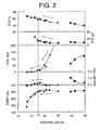
- Fig. 2 illustrates the relationship between the air/fuel ratio (intake air quantity), exhaust gas characteristic, and engine performance.
- Fig. 3 illustrates the relationship between the valve opening degree of an intake throttle valve 13, pressure inside cylinders, and heat generation ratio.
- Fig. 4 is an example of a target intake air quantity map.
- Fig. 5a illustrates the relationship between the intake air quantity and EGR ratio.
- Fig. 5b illustrates the relationship between the intake air quantity and opening degree of the intake throttle valve.
- Fig. 5c illustrates the relationship between the intake air quantity and opening degree of the EGR valve.
- Fig. 1 is a schematic view of a diesel engine of the embodiment.
- the reference numeral 1 stands for an engine body.
- the engine body 1 is connected to an intake channel 2 and an exhaust channel 3.
- the diesel engine of the present embodiment comprises an EGR (exhaust gas recirculation) unit 5 for returning part of exhaust gas into the combustion chamber of the engine body.
- EGR exhaust gas recirculation
- the EGR unit 5 comprises an EGR (exhaust gas recirculation) channel 6 connecting the intake channel 2 and exhaust channel 3, an EGR (exhaust gas recirculation) valve 7 for changing the EGR (exhaust gas recirculation) ratio or EGR (exhaust gas recirculation) quantity (simply referred to hereinbelow as "EGR ratio”) by changing the channel surface area of the EGR(exhaust gas recirculation) channel 6, and an EGR cooler 9 for cooling the EGR gas.
- EGR ratio exhaust gas recirculation
- an air cleaner 10 In the intake channel 2, an air cleaner 10, a MAF (mass air flow) sensor 11 (intake air quantity detection means) for detecting the quantity of air (MAF) that passed through the air cleaner 10, an intercooler 12 for cooling the intake air, and an intake throttle valve 13 for changing the intake air quantity (new air flow rate) upstream of the connection portion (EGR gas introduction portion) of the EGR channel 6 and intake channel 2, are provided.
- the MAF sensor 11 is provided upstream of the EGR gas introduction portion and detects the flow rate of intake air (new gas) containing no EGR gas.
- a variable-capacity turbo 14 (variable supercharger) is provided in the intake channel 2 and exhaust channel 3.
- an exhaust gas turbine 15 is provided downstream of the connection portion of the EGR channel 6 in the exhaust channel 3, and a compressor 16 is provided upstream of the intake throttle valve 13 in the intake channel 2.
- Those exhaust gas turbine 15 and compressor 16 are linked together via a rotary shaft 18.
- a boost pressure adjustment valve 17 boost pressure adjustment means for changing the flow rate of the exhaust gas introduced into the exhaust gas turbine 15 is provided on the inlet side of the exhaust gas turbine 15, and the boost pressure of the intake air that is created by the compressor 16 can be adjusted by changing the valve opening degree of the boost pressure adjustment valve 17.
- An ECU (electronic control unit) 19 (control means) is provided for electronic control of the diesel engine.
- the ECU 19 detects the operation state of the engine from various sensors provided in the diesel engine and controls the fuel injection system of the engine body 1, EGR valve 7, intake throttle valve 13 and boost pressure adjustment valve 17 based on the engine operation state.
- the various sensor includes a boost pressure sensor 20 for detecting the boost pressure in the intake channel 2, a position sensor 21 for detecting the opening degree of the intake throttle valve 13, a position sensor 22 for detecting the valve opening degree of the EGR valve 7, a temperature sensor 23 for detecting the temperature of the intake air (new air) flowing in the MAF sensor 11, a position sensor 25 for detecting the valve opening degree of the boost pressure adjustment valve 17, an engine revolution sensor (not shown in the figure) for detecting the revolution speed of the crank shaft of the engine body 1, and an accelerator opening degree sensor (not shown in the figure) for detecting the accelerator opening degree.
- the detected values of each sensor are inputted into the ECU 19.
- a map having the fuel injection timing, fuel injection quantity, and fuel injection pressure set therein is stored in advance for each engine operation state (engine revolution speed, accelerator opening degree, and the like) in the ECU 19.
- the ECU 19 determines the target values of the fuel injection timing, fuel injection quantity and fuel injection pressure from the map based on the actual engine operation state detected by the sensors and adequately controls the fuel injection system (not shown in the figure) based on the target values.
- the diesel engine of the present embodiment implements the above-described premix combustion at least in the prescribed engine operation region (operation state).
- the ECU 19 implements fuel injection prior to the compression top dead center in the prescribed operation region, and the fuel (gas mixture) is compressed and self-ignites after the fuel injection has been completed.
- NOx nitrogen oxide
- the ECU 19 at least in the operation region where the premix combustion is implemented, determines the target intake air quantity (new gas quantity) necessary for igniting the fuel or mixture (intake air (new gas) + EGR gas + fuel) at the target timing (optimum timing) based on the engine operation state, feedback controls the valve opening degree of the intake throttle valve 13 and/or EGR valve 7 correspondingly to the actual intake air quantity detected by the MAF sensor 11, and matches the actual intake air quantity with the target intake air quantity.
- the ignition timing of the mixture changes depending on the fuel ignition timing, fuel ignition quantity, and oxygen concentration in the mixture.
- oxygen concentration can be replaced with oxygen quantity, air/fuel ratio, EGR ratio or quantity, inert gas concentration, or other physical parameters corresponding thereto, but here the explanation will be conducted by using oxygen concentration as a representative physical parameter.
- the fuel injection timing and fuel injection quantity are uniquely determined by the engine operation state, and the oxygen concentration (target oxygen concentration) necessary for igniting the mixture at the target optimum timing can be determined by a test or simulation for each engine operation state.
- the oxygen concentration in the mixture depends of the intake air quantity (new gas quantity). Therefore, the intake air quantity (target intake air quantity) necessary to obtain the above-described target oxygen concentration is determined by a test or simulation and stored as a map in advance in the ECU 19.
- the ECU 19 determines the target intake air quantity from the map based on the actual engine operation state and then feedback controls the valve opening degree of the intake throttle valve 13 and/or EGR valve 7 so that the actual intake air quantity detected by the MAF sensor 11 matches the target intake air quantity.
- the ignition timing of the fuel (mixture) in the premix combustion can be always optimally controlled. Therefore, a sufficient exhaust gas purification effect can be obtained and negative effects accompanying an inadequate ignition timing, such as efficiency degradation or noise generation, can be avoided.
- the diesel engine in accordance with the present invention does not use the boost pressure adjustment valve 17 for controlling the intake air quantity.
- the ECU 19 stores separately the map in which the optimum valve opening degree of the boost pressure adjustment valve 17 is set for each engine operation state (engine revolution speed, fuel injection quantity, and the like), and the ECU 19 controls the valve opening degree of the boost pressure adjustment valve 17 according to the map, irrespectively of the above-described target intake air quantity. Therefore, the boost pressure is always at a level matching the engine operation state and no degradation of fuel consumption or negative effect on boost pressure increase during acceleration are induced.
- the intake air quantity also changes, but this change can be compensated (absorbed) by the feedback control of the intake throttle valve 13 and/or EGR valve 7. Therefore, the target intake air quantity can be reliable matched with the actual intake air quantity.
- the air/fuel ratio as a representative value indicating the intake air quantity is plotted against the ordinate; it means that the higher is the air/fuel ratio, the larger is the intake air quantity (but the fuel injection quantity is constant).
- the EGR ratio, THC (total hydrocarbon), exhaust quantity, NOx (nitrogen oxide) exhaust quantity, smoke exhaust quantity, and brake mean effective pressure (BMEP) are plotted on the ordinate in the figure, in the order of description starting from the upper section.
- This figure shows the results obtained by varying the air/fuel ratio (intake air quantity) by changing only the valve opening degree of the intake throttle valve 13, while fixing the valve opening degree of the EGR valve 7.
- the line connecting the white points represents the case where the valve opening degree of the EGR valve 7 was fixed at 20%
- the line connecting the triangular points represents the case where the valve opening degree of the EGR valve 7 was fixed at 40%.
- the line connecting rectangular points in the figure indicates, for the reference, the results obtained when the conventional combustion was conducted by injecting the fuel in the compression upper dead center of the piston.
- the engine revolution speed and fuel injection quantity are constant for all the lines. In each line, the direction shown by an arrow indicates the decrease in the valve opening degree of the intake throttle valve 13.
- valve opening degree of the intake throttle valve 13 changes, the amount of generated THC (total hydrocarbon), NOx (nitrogen oxide), and smoke also changes. This is because changes in the valve opening degree of the intake throttle valve 13 cause changes in the oxygen concentration in the mixture (or air/fuel ratio or intake air quantity) and changes in the fuel ignition timing.
- the ignition timing of the mixture at the time of this air/fuel ratio B is the above-described target ignition timing (optimum ignition timing), and the intake air quantity corresponding to this air/fuel ratio B is a target intake air quantity.
- valve opening degree in other words, the intake air quantity
- crank angle is plotted against the abscissa.
- the pressure inside the cylinder is shown in the upper part, the heat generation ratio is shown in the medium part, and the application timing of the conduction current (drive current) corresponding to the fuel injection valve of the engine body 1 is shown in the lower part of the ordinate.
- FIG. 3 shows the results obtained when the valve opening degree of the intake throttle valve 13 changed to pattern 3.
- the decrease in the valve opening degree of the intake throttle valve 13 delays the period at which the pressure inside the cylinder and heat generation ratio start rising. This result means that when the valve opening degree of the intake throttle valve 13 decreases, that is, when the intake air quantity decreases, the ignition timing of the gas mixture becomes delayed. Furthermore, it is clear that as the ignition timing of the gas mixture becomes delayed, the maximum values of the pressure inside the cylinder and heat generation ratio become smaller.
- the intake air quantity necessary for igniting the gas mixture at the target timing differs between the operation modes of the engine. For this reason, the intake air quantity necessary for igniting the gas mixture at the target timing is found in advance for each operation mode of the engine by a test or simulation and stored as a target intake air quantity map in the ECU 19.
- FIG. 4 An example of the target intake air quantity map is shown in Fig. 4.
- the engine revolution speed is plotted against the abscissa
- the fuel injection quantity (corresponds to the engine load) is plotted against the ordinate.
- line C shows a switching point between the premix combustion and usual diffusion combustion.
- the ECU 19 implements the premix combustion in the operation region below the line C.
- the premix combustion is implemented in the operation region with a comparatively low load. This is because, the fuel injection quantity increases in the high-load operation region and, therefore, there is a risk of the premix combustion generating knocking.
- lines D1 to D4 disposed below the line C represent the target intake air quantity map. When they are on the same line, it means that the target intake air quantities are equal to each other. As follows from the figure, as the fuel injection quantity decreases (as the engine load decreases), the target intake air quantity decreases.
- the ECU 19 determines the target intake air quantity from the map based on the actual engine revolution speed detected by the engine revolution sensor and a fuel injection quantity determined from a map based on the engine revolution speed and accelerator opening degree.
- the control of the intake throttle valve 13 and/or EGR valve 7 is so conducted that the actual intake air quantity detected by the MAF sensor 11 matches the target air intake quantity, but in the present embodiment the valve to be controlled is selected based on the value of the target intake air quantity determined from the map.
- the intake air quantity is plotted against the abscissa
- the EGR ratio, valve opening degree of the intake throttle valve 13, and valve opening degree of the EGR valve 7 are plotted against the ordinate in Fig. 5a, Fig. 5b, and Fig. 5c, respectively.
- the intake throttle valve 13 and EGR valve 7 have respective regions with high sensitivity with respect to the intake air quantity (regions with high controllability).
- the intake throttle valve 13 demonstrates high controllability in a region where the intake air quantity is N1 or less
- the EGR valve 7 demonstrates controllability in a region where the intake air quantity is more than N2.
- the controllability of the intake throttle valve 13 and EGR valve 7 in the region with intermediate intake air quantity (N1 to N2) is not that high.
- the diesel engine of the present embodiment is so designed that the intake air quantity can be controlled in a simple and adequate manner by considering the above-described characteristics of the intake throttle valve 13 and EGR valve 7. This is explained below in greater detail.
- the ECU 19 fixes the opening degree of the EGR valve 7 (usually, fixed to a fully open state) and controls the opening and closing of only the intake throttle valve 13.
- the target intake air quantity is larger than the first set value N1 and equal to or less than the second set value (N2 in Fig. 5b and Fig.
- the ECU 19 controls the opening and closing of both the EGR valve 7 and the intake throttle valve 13.
- the ECU 19 fixes the opening degree of the intake throttle valve 13 (usually fixes to a fully open state) and controls the opening and closing of only the EGR valve 7.
- the first set value N1 and second set value N2 vary depending on the characteristics of the EGR unit 5 (for example, performance of the EGR cooler 9), they are determined by preliminary tests.
- the intake throttle valve 13 or EGR valve 7 has a high sensitivity with respect to the intake air quantity (controllability is high)
- the intake air quantity can be controlled finely and in an easy manner.
- a high controllability can be maintained by controlling both valves. Therefore, the intake air quantity can be reliably controlled.
- both the intake throttle valve 13 and the EGR valve 7 are used for controlling the intake air quantity, the range of possible control of the intake air quantity is expanded. Therefore, optimization of the ignition timing can be conducted reliably.
- the present invention is not limited to the above-described embodiment.
- variable-capacity turbo (VGS) 14 was described as a variable supercharger, but the present invention is not limited to such a configuration and other variable superchargers such as a variable-nozzle turbo (VNT), two-stage turbo (system with switching between two turbo), or a variable turbo using a westgate may be used.
- VNT variable-nozzle turbo
- two-stage turbo system with switching between two turbo
- a variable turbo using a westgate may be used.
- the control quantity (valve opening degree) of the boost pressure adjustment means may be constant, regardless of the engine operation state.
- the boost pressure becomes constant. Therefore, the control of intake air quantity with the intake throttle valve 13 and/or EGR valve 7 can be conducted even easier.
- the boost pressure adjustment valve 17 is fixed in an almost fully open state, an effective supercharge response can be ensured in a transition from a low-load region where the premix combustion is implemented to a high-load region where the usual combustion is implemented.
- the present invention does not use the boost pressure adjustment means for controlling the intake air quantity, it is also readily applicable to diesel engines that are not equipped with a variable supercharger.
- the target intake air quantity was determined based on the target oxygen quantity, but the present invention is not limited to such a procedure and the target intake air quantity may be also determined by using any one of the quantity of oxygen, oxygen concentration, air/fuel ratio, EGR ratio, and inert gas concentration, or a combination of two or more thereof, or other physical parameters corresponding thereto.
- the intake throttle valve 13 and/or EGR valve 7 were controlled so that the actual intake air quantity detected by the MAF sensor 11 becomes the target intake air quantity, but the ignition timing of the mixture can be detected by the cylinder pressure sensor and the intake throttle valve 13 and/or EGR valve 7 can be also so controlled that the actual ignition timing matches the predetermined optimum ignition timing.
- Another possibility is to determine the target oxygen quantity necessary for igniting the fuel at the target timing based on the engine operation state, to provide O 2 (oxygen) sensor in the combustion chamber of the engine body 1 or in the intake port, and to control the intake throttle valve 13 and/or EGR valve 7 so that the actual oxygen quantity (quantity of oxygen contained in the mixture) detected with the O 2 sensor matches the target oxygen quantity.
- O 2 oxygen
Abstract
Description
Claims (10)
- A diesel engine comprising an EGR (exhaust gas recirculation) valve, an intake throttle valve provided upstream of an EGR gas inlet portion in an intake channel, control means for controlling the EGR valve and the intake throttle valve, and intake air quantity detection means for detecting an intake air quantity upstream of an EGR gas inlet portion in the intake channel, the diesel engine implementing a premix combustion in which a fuel is injected earlier than a compression top dead center and ignited after the injection is completed at least in a prescribed operation region, characterized in that
the control means, at least in the operation region in which the premix combustion is implemented, determines a target intake air quantity necessary for igniting the fuel at an target timing based on an engine operation state and controls the intake throttle valve and/or the EGR valve so that an actual intake air quantity detected by the intake air quantity detection means matches the target intake air quantity. - The diesel engine according to claim 1, characterized in that
target values of at least any one of quantity of oxygen, oxygen concentration, air/fuel ratio, EGR ratio, and inert gas concentration necessary for the fuel to be ignited at an optimum timing, or a combination of two or more thereof, or other physical parameters corresponding thereto are determined for each engine operation state, and the target intake air quantity is determined such that at least any one of the quantity of oxygen, oxygen concentration, air/fuel ratio, EGR ratio, and inert gas concentration, or a combination of two or more thereof, or other physical parameters corresponding thereto match the target values. - The diesel engine according to claim 1 or 2, characterized in that
the control means
fixes an opening degree of the EGR valve and controls opening and closing of only the intake throttle valve when the target intake air quantity is equal to or less than a first set value;
controls the opening and closing of both the EGR valve and the intake throttle valve when the target intake air quantity is larger than the first set value and equal to or less than a second set value; and
fixes the opening degree of the intake throttle valve and controls the opening and closing of only the EGR valve when the target intake air quantity is larger than the second set value. - The diesel engine according to claim 3, characterized in that
the control means
fixes the opening degree of the EGR valve to a full open state and controls the opening and closing of only the intake throttle valve when the target intake air quantity is equal to or less than the first set value; and
fixes the opening degree of the intake throttle valve to a full open state and controls the opening and closing of only the EGR valve when the target intake air quantity is larger than the second set value. - The diesel engine according to any one of claims 1 to 4, further comprising a variable supercharger equipped with boost pressure adjustment means, characterized in that
the control means controls the boost pressure adjustment means according to a map that was set in advance, irrespectively of the target intake air quantity. - The diesel engine according to claim 5, characterized in that the control means makes a control amount of the boost pressure adjustment means constant in the operation region where the premix combustion is implemented.
- The diesel engine according to claim 6, characterized in that
the boost pressure adjustment means comprises a boost pressure adjustment valve for changing the flow rate of exhaust gases introduced into an exhaust turbine provided in an exhaust channel, and
the control means fixes the boost pressure adjustment valve to a fully closed state in the operation region where the premix combustion is implemented. - A control method for a diesel engine comprising an EGR valve, an intake throttle valve provided upstream of an EGR gas inlet portion in an intake channel, control means for controlling the EGR valve and the intake throttle valve, and intake air quantity detection means for detecting an intake air quantity upstream of an EGR gas inlet portion in the intake channel, the diesel engine implementing a premix combustion in which a fuel is injected earlier than a compression top dead center and ignited after the injection is completed at least in a prescribed operation region, the method comprising the steps of:determining a target intake air quantity necessary for igniting the fuel at a target timing based on an engine operation state; andcontrolling the intake throttle valve and/or the EGR valve so that an actual intake air quantity detected by the intake air quantity detection means matches the target intake air quantity.
- A diesel engine comprising an EGR valve, an intake throttle valve provided upstream of an EGR gas inlet portion in an intake channel, control means for controlling the EGR valve and the intake throttle valve, and oxygen quantity detection means for detecting the oxygen quantity in the gas mixture, the diesel engine implementing a premix combustion in which a fuel is injected earlier than a compression top dead center and ignited after the injection is completed at least in a prescribed operation region, characterized in that
the control means,
at least in the operation region in which the premix combustion is implemented, determines a target oxygen quantity necessary for igniting the fuel at a target timing based on an engine operation state and controls the intake throttle valve and/or the EGR valve so that an actual oxygen quantity detected by the oxygen quantity detection means matches the target oxygen quantity. - A control method for a diesel engine comprising an EGR valve, an intake throttle valve provided upstream of an EGR gas inlet portion in an intake channel, control means for controlling the EGR valve and the intake throttle valve, and oxygen quantity detection means for detecting the oxygen quantity in the gas mixture, the diesel engine implementing a premix combustion in which a fuel is injected earlier than a compression top dead center and ignited after the injection is completed at least in a prescribed operation region, the method comprising the steps of:determining a target oxygen quantity necessary for igniting the fuel at a target timing based on an engine operation state; andcontrolling the intake throttle valve and/or the EGR valve so that an actual oxygen quantity detected by the oxygen quantity detection means matches the target oxygen quantity.
Applications Claiming Priority (2)
| Application Number | Priority Date | Filing Date | Title |
|---|---|---|---|
| JP2004057556 | 2004-03-02 | ||
| JP2004057556A JP2005248748A (en) | 2004-03-02 | 2004-03-02 | Diesel engine |
Publications (3)
| Publication Number | Publication Date |
|---|---|
| EP1571322A2 true EP1571322A2 (en) | 2005-09-07 |
| EP1571322A3 EP1571322A3 (en) | 2007-03-14 |
| EP1571322B1 EP1571322B1 (en) | 2011-10-05 |
Family
ID=34747623
Family Applications (1)
| Application Number | Title | Priority Date | Filing Date |
|---|---|---|---|
| EP05004149A Expired - Fee Related EP1571322B1 (en) | 2004-03-02 | 2005-02-25 | Diesel engine |
Country Status (4)
| Country | Link |
|---|---|
| US (1) | US7188606B2 (en) |
| EP (1) | EP1571322B1 (en) |
| JP (1) | JP2005248748A (en) |
| CN (1) | CN1664339A (en) |
Cited By (4)
| Publication number | Priority date | Publication date | Assignee | Title |
|---|---|---|---|---|
| WO2007063258A1 (en) * | 2005-12-02 | 2007-06-07 | Renault S.A.S. | Adaptive method for controlling a motor |
| US20120186564A1 (en) * | 2011-01-25 | 2012-07-26 | Ford Global Technologies, Llc | Method for determining the oxygen concentration o2 in a gas flow |
| AT501012B1 (en) * | 2006-02-09 | 2014-05-15 | Avl List Gmbh | Method for controlling the air system in a combustion engine |
| FR3033596A1 (en) * | 2015-03-12 | 2016-09-16 | Peugeot Citroen Automobiles Sa | METHOD FOR CONTROLLING AN INTERNAL COMBUSTION ENGINE |
Families Citing this family (25)
| Publication number | Priority date | Publication date | Assignee | Title |
|---|---|---|---|---|
| DE10229620B4 (en) * | 2002-06-29 | 2006-05-11 | Daimlerchrysler Ag | Method for determining the exhaust gas recirculation quantity |
| JP4186899B2 (en) * | 2004-09-30 | 2008-11-26 | 株式会社日立製作所 | Exhaust gas recirculation control device |
| JP4049158B2 (en) * | 2005-03-09 | 2008-02-20 | トヨタ自動車株式会社 | Fuel injection control device for internal combustion engine |
| JP4244979B2 (en) | 2005-09-22 | 2009-03-25 | トヨタ自動車株式会社 | Supercharging pressure control device for internal combustion engine |
| JP2007120330A (en) * | 2005-10-25 | 2007-05-17 | Toyota Industries Corp | Internal combustion engine performing premixed compression ignition combustion |
| US7231906B1 (en) * | 2006-06-27 | 2007-06-19 | Gm Global Technology Operations, Inc. | Simultaneous EGR correction and individual cylinder combustion phase balancing |
| FR2926114B1 (en) * | 2008-01-03 | 2012-12-14 | Valeo Sys Controle Moteur Sas | EGR LOOP OF AN INTERNAL COMBUSTION ENGINE OF A MOTOR VEHICLE |
| FR2926113A1 (en) * | 2008-01-03 | 2009-07-10 | Valeo Sys Controle Moteur Sas | EGR LOOP OF AN INTERNAL COMBUSTION ENGINE OF A MOTOR VEHICLE |
| GB2460053B (en) * | 2008-05-14 | 2012-06-13 | Gm Global Tech Operations Inc | A method for controlling the EGR and the throttle valves in an internal combustion engine |
| JP5236578B2 (en) * | 2009-06-11 | 2013-07-17 | 本田技研工業株式会社 | Control device for internal combustion engine |
| US8251049B2 (en) * | 2010-01-26 | 2012-08-28 | GM Global Technology Operations LLC | Adaptive intake oxygen estimation in a diesel engine |
| WO2012001940A1 (en) * | 2010-06-30 | 2012-01-05 | Mazda Motor Corporation | Starter and starting method of compression self-ignition engine |
| US9181904B2 (en) * | 2010-08-10 | 2015-11-10 | Ford Global Technologies, Llc | Method and system for exhaust gas recirculation control |
| WO2014011326A1 (en) * | 2012-07-13 | 2014-01-16 | International Engine Intellectual Property Company, Llc | System and method of controlling combustion in an engine |
| US9133757B2 (en) | 2012-10-10 | 2015-09-15 | Ford Global Technologies, Llc | Engine control system and method |
| FR3000135B1 (en) * | 2012-12-20 | 2018-08-10 | Valeo Systemes De Controle Moteur | COOLANT FLUID SUPPLY FLUID FOR COOLED COMPONENT AND COMPONENT EQUIPPED WITH SUCH FLANGE |
| US9708974B2 (en) * | 2013-01-21 | 2017-07-18 | Ford Global Technologies, Llc | Low-pressure EGR control during compressor bypass valve operation |
| JP2015014257A (en) * | 2013-07-05 | 2015-01-22 | スズキ株式会社 | Ignition timing control device for internal combustion engine |
| JP6230337B2 (en) * | 2013-08-30 | 2017-11-15 | ダイハツ工業株式会社 | Control device for internal combustion engine |
| KR101829042B1 (en) * | 2013-10-28 | 2018-02-13 | 얀마 가부시키가이샤 | Auxiliary-chamber-type gas engine |
| JP6375912B2 (en) * | 2014-12-05 | 2018-08-22 | トヨタ自動車株式会社 | Control device for internal combustion engine |
| BR102016006973A2 (en) * | 2015-03-31 | 2016-11-01 | Toyota Motor Co Ltd | internal combustion engine control device |
| JP6531516B2 (en) * | 2015-06-24 | 2019-06-19 | いすゞ自動車株式会社 | Internal combustion engine intake and exhaust system |
| JP6528558B2 (en) * | 2015-06-24 | 2019-06-12 | いすゞ自動車株式会社 | Internal combustion engine intake and exhaust system |
| CN112901377B (en) * | 2021-02-10 | 2022-04-01 | 东风汽车集团股份有限公司 | Method for determining activation state of mixing valve of low-pressure EGR system |
Citations (2)
| Publication number | Priority date | Publication date | Assignee | Title |
|---|---|---|---|---|
| JP2001020784A (en) | 1998-02-23 | 2001-01-23 | Cummins Engine Co Inc | Method for controlling pre-mix charge compression ignition engine and combustion timing |
| JP2002327638A (en) | 2001-04-27 | 2002-11-15 | Nissan Motor Co Ltd | Control device of diesel engine |
Family Cites Families (12)
| Publication number | Priority date | Publication date | Assignee | Title |
|---|---|---|---|---|
| KR100237533B1 (en) * | 1996-03-08 | 2000-01-15 | 나까무라 히로까즈 | Device for controlling cylinder fuel injection type internal combustion engine |
| JP3116876B2 (en) * | 1997-05-21 | 2000-12-11 | トヨタ自動車株式会社 | Internal combustion engine |
| JP3094974B2 (en) * | 1997-09-16 | 2000-10-03 | トヨタ自動車株式会社 | Compression ignition type internal combustion engine |
| JP2000130200A (en) * | 1998-10-30 | 2000-05-09 | Mitsubishi Motors Corp | Controller for diesel engine |
| JP3743195B2 (en) | 1999-02-26 | 2006-02-08 | ふそうエンジニアリング株式会社 | Premixed compression ignition internal combustion engine |
| FR2816660B1 (en) * | 2000-11-15 | 2003-05-02 | Sagem | METHOD AND DEVICE FOR CONTROLLING THE OPERATION OF A SELF-IGNITION INTERNAL COMBUSTION ENGINE |
| JP2003138952A (en) * | 2001-11-05 | 2003-05-14 | Mitsubishi Motors Corp | Diesel engine |
| US6732723B2 (en) * | 2002-04-04 | 2004-05-11 | Ford Global Technologies, Llc | Method and system for controlling EGR rate in diesel engines |
| US6857263B2 (en) * | 2002-08-08 | 2005-02-22 | The United States Of America As Represented By The Administrator Of The Environmental Protection Agency | Low emission diesel combustion system with low charge-air oxygen concentration levels and high fuel injection pressures |
| ES2430164T3 (en) * | 2002-09-09 | 2013-11-19 | Toyota Jidosha Kabushiki Kaisha | Control device for an internal combustion engine |
| JP4472932B2 (en) * | 2003-02-07 | 2010-06-02 | いすゞ自動車株式会社 | Engine combustion control device |
| JP4285141B2 (en) * | 2003-07-31 | 2009-06-24 | 日産自動車株式会社 | Fuel injection control device for diesel engine |
-
2004
- 2004-03-02 JP JP2004057556A patent/JP2005248748A/en active Pending
-
2005
- 2005-02-25 EP EP05004149A patent/EP1571322B1/en not_active Expired - Fee Related
- 2005-02-28 US US11/068,953 patent/US7188606B2/en active Active
- 2005-03-02 CN CN2005100518191A patent/CN1664339A/en active Pending
Patent Citations (2)
| Publication number | Priority date | Publication date | Assignee | Title |
|---|---|---|---|---|
| JP2001020784A (en) | 1998-02-23 | 2001-01-23 | Cummins Engine Co Inc | Method for controlling pre-mix charge compression ignition engine and combustion timing |
| JP2002327638A (en) | 2001-04-27 | 2002-11-15 | Nissan Motor Co Ltd | Control device of diesel engine |
Cited By (7)
| Publication number | Priority date | Publication date | Assignee | Title |
|---|---|---|---|---|
| WO2007063258A1 (en) * | 2005-12-02 | 2007-06-07 | Renault S.A.S. | Adaptive method for controlling a motor |
| FR2894291A1 (en) * | 2005-12-02 | 2007-06-08 | Renault Sas | ADAPTIVE METHOD FOR CONTROLLING AN ENGINE |
| AT501012B1 (en) * | 2006-02-09 | 2014-05-15 | Avl List Gmbh | Method for controlling the air system in a combustion engine |
| US20120186564A1 (en) * | 2011-01-25 | 2012-07-26 | Ford Global Technologies, Llc | Method for determining the oxygen concentration o2 in a gas flow |
| US9051892B2 (en) * | 2011-01-25 | 2015-06-09 | Ford Global Technologies, Llc | Method for determining the oxygen concentration O 2 in a gas flow |
| US10323583B2 (en) | 2011-01-25 | 2019-06-18 | Ford Global Technologies, Llc | Method for determining the oxygen concentration O2 in a gas flow |
| FR3033596A1 (en) * | 2015-03-12 | 2016-09-16 | Peugeot Citroen Automobiles Sa | METHOD FOR CONTROLLING AN INTERNAL COMBUSTION ENGINE |
Also Published As
| Publication number | Publication date |
|---|---|
| EP1571322B1 (en) | 2011-10-05 |
| EP1571322A3 (en) | 2007-03-14 |
| US20050193978A1 (en) | 2005-09-08 |
| US7188606B2 (en) | 2007-03-13 |
| JP2005248748A (en) | 2005-09-15 |
| CN1664339A (en) | 2005-09-07 |
Similar Documents
| Publication | Publication Date | Title |
|---|---|---|
| US7188606B2 (en) | Diesel engine | |
| US7739026B2 (en) | Control apparatus for combustion engine of premixed compression self-ignition type | |
| JP3743195B2 (en) | Premixed compression ignition internal combustion engine | |
| EP2708722B1 (en) | Control apparatus and method for an internal combustion engine | |
| US6941929B2 (en) | Combustion control system for internal combustion engine | |
| US7254473B2 (en) | Compression ignition engine control apparatus ensuring desired output of torque | |
| US20080167786A1 (en) | Engine control apparatus | |
| US8315777B2 (en) | Control apparatus and control method for internal combustion engine | |
| KR20060051868A (en) | Engine | |
| JP2010038012A (en) | Device for controlling internal combustion engine | |
| US10961943B1 (en) | Method and system for controlling combustion of natural gas engine | |
| JP2007205181A (en) | Four cycle internal combustion engine | |
| EP1413724A2 (en) | Internal combustion engine control during gear shift | |
| EP2772632B1 (en) | Control device for internal combustion engine | |
| JP2009203918A (en) | Operation control method of gasoline engine | |
| JP4735497B2 (en) | Fuel cetane number discrimination system for compression ignition type internal combustion engine | |
| US7367311B2 (en) | Control system for compression ignition internal combustion engine | |
| JP4265382B2 (en) | Premixed compression ignition internal combustion engine | |
| JP3979287B2 (en) | Premixed compression ignition internal combustion engine | |
| EP2778377B1 (en) | Control device of internal combustion engine | |
| JP3835238B2 (en) | Diesel engine control device | |
| WO2010095258A1 (en) | Internal combustion engine | |
| JP6844237B2 (en) | Internal combustion engine control device | |
| JP2010196525A (en) | Combustion control device of compression-ignition internal combustion engine | |
| JP4775225B2 (en) | Control system for compression ignition internal combustion engine |
Legal Events
| Date | Code | Title | Description |
|---|---|---|---|
| PUAI | Public reference made under article 153(3) epc to a published international application that has entered the european phase |
Free format text: ORIGINAL CODE: 0009012 |
|
| AK | Designated contracting states |
Kind code of ref document: A2 Designated state(s): AT BE BG CH CY CZ DE DK EE ES FI FR GB GR HU IE IS IT LI LT LU MC NL PL PT RO SE SI SK TR |
|
| AX | Request for extension of the european patent |
Extension state: AL BA HR LV MK YU |
|
| PUAL | Search report despatched |
Free format text: ORIGINAL CODE: 0009013 |
|
| AK | Designated contracting states |
Kind code of ref document: A3 Designated state(s): AT BE BG CH CY CZ DE DK EE ES FI FR GB GR HU IE IS IT LI LT LU MC NL PL PT RO SE SI SK TR |
|
| AX | Request for extension of the european patent |
Extension state: AL BA HR LV MK YU |
|
| 17P | Request for examination filed |
Effective date: 20070420 |
|
| AKX | Designation fees paid |
Designated state(s): DE FR GB IT |
|
| 17Q | First examination report despatched |
Effective date: 20080702 |
|
| GRAP | Despatch of communication of intention to grant a patent |
Free format text: ORIGINAL CODE: EPIDOSNIGR1 |
|
| GRAS | Grant fee paid |
Free format text: ORIGINAL CODE: EPIDOSNIGR3 |
|
| GRAA | (expected) grant |
Free format text: ORIGINAL CODE: 0009210 |
|
| AK | Designated contracting states |
Kind code of ref document: B1 Designated state(s): DE FR GB IT |
|
| REG | Reference to a national code |
Ref country code: GB Ref legal event code: FG4D |
|
| REG | Reference to a national code |
Ref country code: DE Ref legal event code: R096 Ref document number: 602005030310 Country of ref document: DE Effective date: 20111201 |
|
| PLBE | No opposition filed within time limit |
Free format text: ORIGINAL CODE: 0009261 |
|
| STAA | Information on the status of an ep patent application or granted ep patent |
Free format text: STATUS: NO OPPOSITION FILED WITHIN TIME LIMIT |
|
| PG25 | Lapsed in a contracting state [announced via postgrant information from national office to epo] |
Ref country code: IT Free format text: LAPSE BECAUSE OF FAILURE TO SUBMIT A TRANSLATION OF THE DESCRIPTION OR TO PAY THE FEE WITHIN THE PRESCRIBED TIME-LIMIT Effective date: 20111005 |
|
| 26N | No opposition filed |
Effective date: 20120706 |
|
| REG | Reference to a national code |
Ref country code: DE Ref legal event code: R097 Ref document number: 602005030310 Country of ref document: DE Effective date: 20120706 |
|
| REG | Reference to a national code |
Ref country code: FR Ref legal event code: PLFP Year of fee payment: 11 |
|
| PGFP | Annual fee paid to national office [announced via postgrant information from national office to epo] |
Ref country code: DE Payment date: 20150218 Year of fee payment: 11 |
|
| REG | Reference to a national code |
Ref country code: DE Ref legal event code: R082 Ref document number: 602005030310 Country of ref document: DE Representative=s name: SCHAUMBURG & PARTNER PATENTANWAELTE GBR, DE Ref country code: DE Ref legal event code: R082 Ref document number: 602005030310 Country of ref document: DE Representative=s name: SCHAUMBURG & PARTNER PATENTANWAELTE MBB, DE Ref country code: DE Ref legal event code: R082 Ref document number: 602005030310 Country of ref document: DE Representative=s name: SCHAUMBURG UND PARTNER PATENTANWAELTE MBB, DE |
|
| PGFP | Annual fee paid to national office [announced via postgrant information from national office to epo] |
Ref country code: FR Payment date: 20150210 Year of fee payment: 11 Ref country code: GB Payment date: 20150225 Year of fee payment: 11 |
|
| REG | Reference to a national code |
Ref country code: DE Ref legal event code: R119 Ref document number: 602005030310 Country of ref document: DE |
|
| GBPC | Gb: european patent ceased through non-payment of renewal fee |
Effective date: 20160225 |
|
| REG | Reference to a national code |
Ref country code: FR Ref legal event code: ST Effective date: 20161028 |
|
| PG25 | Lapsed in a contracting state [announced via postgrant information from national office to epo] |
Ref country code: GB Free format text: LAPSE BECAUSE OF NON-PAYMENT OF DUE FEES Effective date: 20160225 Ref country code: DE Free format text: LAPSE BECAUSE OF NON-PAYMENT OF DUE FEES Effective date: 20160901 Ref country code: FR Free format text: LAPSE BECAUSE OF NON-PAYMENT OF DUE FEES Effective date: 20160229 |