EP1571286A2 - A grate and fabrication method thereof - Google Patents
A grate and fabrication method thereof Download PDFInfo
- Publication number
- EP1571286A2 EP1571286A2 EP05425126A EP05425126A EP1571286A2 EP 1571286 A2 EP1571286 A2 EP 1571286A2 EP 05425126 A EP05425126 A EP 05425126A EP 05425126 A EP05425126 A EP 05425126A EP 1571286 A2 EP1571286 A2 EP 1571286A2
- Authority
- EP
- European Patent Office
- Prior art keywords
- rod
- bar
- bars
- grate
- pin
- Prior art date
- Legal status (The legal status is an assumption and is not a legal conclusion. Google has not performed a legal analysis and makes no representation as to the accuracy of the status listed.)
- Granted
Links
Images



Classifications
-
- E—FIXED CONSTRUCTIONS
- E06—DOORS, WINDOWS, SHUTTERS, OR ROLLER BLINDS IN GENERAL; LADDERS
- E06B—FIXED OR MOVABLE CLOSURES FOR OPENINGS IN BUILDINGS, VEHICLES, FENCES OR LIKE ENCLOSURES IN GENERAL, e.g. DOORS, WINDOWS, BLINDS, GATES
- E06B9/00—Screening or protective devices for wall or similar openings, with or without operating or securing mechanisms; Closures of similar construction
- E06B9/02—Shutters, movable grilles, or other safety closing devices, e.g. against burglary
- E06B9/06—Shutters, movable grilles, or other safety closing devices, e.g. against burglary collapsible or foldable, e.g. of the bellows or lazy-tongs type
- E06B9/0607—Shutters, movable grilles, or other safety closing devices, e.g. against burglary collapsible or foldable, e.g. of the bellows or lazy-tongs type comprising a plurality of similar rigid closing elements movable to a storage position
- E06B9/0615—Shutters, movable grilles, or other safety closing devices, e.g. against burglary collapsible or foldable, e.g. of the bellows or lazy-tongs type comprising a plurality of similar rigid closing elements movable to a storage position characterised by the closing elements
- E06B9/063—Bars or rods perpendicular to the closing direction
-
- E—FIXED CONSTRUCTIONS
- E06—DOORS, WINDOWS, SHUTTERS, OR ROLLER BLINDS IN GENERAL; LADDERS
- E06B—FIXED OR MOVABLE CLOSURES FOR OPENINGS IN BUILDINGS, VEHICLES, FENCES OR LIKE ENCLOSURES IN GENERAL, e.g. DOORS, WINDOWS, BLINDS, GATES
- E06B9/00—Screening or protective devices for wall or similar openings, with or without operating or securing mechanisms; Closures of similar construction
- E06B9/02—Shutters, movable grilles, or other safety closing devices, e.g. against burglary
- E06B9/06—Shutters, movable grilles, or other safety closing devices, e.g. against burglary collapsible or foldable, e.g. of the bellows or lazy-tongs type
- E06B9/0607—Shutters, movable grilles, or other safety closing devices, e.g. against burglary collapsible or foldable, e.g. of the bellows or lazy-tongs type comprising a plurality of similar rigid closing elements movable to a storage position
- E06B9/0646—Shutters, movable grilles, or other safety closing devices, e.g. against burglary collapsible or foldable, e.g. of the bellows or lazy-tongs type comprising a plurality of similar rigid closing elements movable to a storage position characterised by the relative arrangement of the closing elements in the stored position
- E06B9/0653—Shutters, movable grilles, or other safety closing devices, e.g. against burglary collapsible or foldable, e.g. of the bellows or lazy-tongs type comprising a plurality of similar rigid closing elements movable to a storage position characterised by the relative arrangement of the closing elements in the stored position stored side by side in the closing plane
- E06B9/0661—Lazy tongue, pantograph or scissor-like systems in the plane of the opening
Definitions
- This invention relates to a slidingly collapsible grate that can be validly used in the building sector for homes, offices and industrial plants, the grate being equipped with a plurality of bars slidingly mounted with respect to the frame and reciprocally coupled two by two by means of a plurality of levers.
- this invention refers to a collapsible grate equipped with a plurality of bars coupled together by a plurality of levers in such a way as to combine easy s witching between an open and a closed position, easy use and a high degree of resistance to break-in attempts.
- This invention also refers to the method for producing the grate in question.
- the known grates are equipped with a box frame substantially rectangular in shape, a pair of horizontal guides which are positioned at the top and bottom of the opening to be closed and which comprise a plurality of vertical bars or posts coupled to the guides by means of sliding blocks so that the bars can slide freely from and to a closed position in the opening.
- Collapsible grates are usually equipped with elements resistant to transverse stress, which are normally designed to connect the bars together two by two in such a way that the grate can be switched from an open position to a closed position by moving the end bar.
- collapsible grate sector has always, albeit unjustly, been considered not particularly worthy of attention, since these collapsible grates are often considered to be a temporary solution or a makeshift with respect to fixed grates.
- Collapsible grates are therefore normally made from low-cost metal materials, with box or extruded elements or more frequently produced by pressing, and normally with a C-shaped cross-section which is easily deformed due to transverse deflection, especially if the elements are of a considerable length.
- the grate comprises a plurality of bars and a plurality of alternating connecting rods.
- Each connecting rod is connected to each of the two bars by means of a pair of substantially identical levers.
- Each connecting rod is therefore shared by a pair of adjacent articulated quadrilaterals, whose respective frames consist of bars positioned immediately upstream and downstream of the connecting rod, and keeps the bars substantially parallel to each other and therefore vertical.
- the bars are spaced fairly widely apart, so in order to increase the resistance to break-in attempts, a plurality of reinforcement panels is foreseen, joining the bars and the connecting rods together and extending along the length of the bars.
- the bars are vertical and the ends of each one are slidingly connected to the frame.
- the bars are also connected to each other in pairs by at least one pair of levers, cross-hinged together and visible when the grate is open.
- Each of the upper ends of the levers of each cross is connected to the corresponding bar by means of a turning pair, while each of the lower ends is connected to the other corresponding bar by means of a sliding pair, and therefore in a freely sliding way.
- Each cross is therefore designed to close when the grate is opened, and to reinforce the grate in the event of maneuvers made transversally to the grate, for example in break-in attempts.
- the grate is equipped with at least one curtain, which is connected vertically to the bars and conceals the grate externally, and with appropriate guide means for the upper and lower ends of the curtain.
- the curtain is fixed to the bars in a plurality of points and cannot be precisely tensioned; it is therefore loose and, after prolonged use, becomes even less taut and not very attractive.
- each bar is enclosed in a slidingly mounted longitudinal sleeve, and the sleeves arranged in succession along the sliding direction of the bars are connected together in pairs by levers.
- These levers are hinged from opposite sides of each sleeve so as to be inclined and constantly parallel to each other.
- the levers are arranged symmetrically with respect to each sleeve, and each sleeve is raised or lowered with respect to the current operating position, shifting the grate between the extended configuration, in which the bars are spaced apart with the grate acting as a closure and obstacle to break-in attempts, and the minimum obstruction position, in which the bars are close together to allow access to the window opening.
- Each sleeve therefore presents a plurality of housings for the lever coupling pins and these housings are arranged in pairs on opposite sides with respect to the axis of the sleeve.
- this construction solution naturally presents notable functioning problems due to the various types of dust that accumulate between each bar and the relative sleeve and which cause a considerable increase in friction between the parts which move during opening and closing of the grate, compromising correct functioning in a short time.
- some known collapsible grates present horizontal guides that delimit the frame at the top and bottom, divided into two C-shaped parts, each representing a side portion of the frame.
- One of the two C-shaped parts normally the one with longer horizontal guides, is rigidly connected to the corresponding sides of the respective window opening, while the remaining C-shaped part, which is shorter, rotates outwards from one side of the window opening.
- the longitudinal extension of this part is calculated in such a way as to completely support the assembly of collapsed bars on the corresponding hinge side.
- the grate sector can be divided into two parts: a first part in which the bars are connected together by means of levers and/or connecting rods and just turning pairs, and a second part in which the bars are connected by means of levers and sliding and turning pairs.
- the first require less maintenance but are not very sturdy, for example as in the case of the US patent 1718649, and must be reinforced with additional parts as the bars are spaced too wide apart, the result being that the respective structure is excessively complex;
- the second present an excessive number of turning pairs and sliding pairs, as in the case of US patent 4006768, thus costing more at source, due to the greater cost of the sliding pairs, the greater delicacy of the structure and the greater level of maintenance required.
- the presence of substantially vertical sliding pairs lowers the resistance of the grate to the application of force transversal to the plane of the grate.
- the grate that presents a combination of turning and sliding pairs for each vertical upright.
- the grate comprises a series of vertical uprights, each slidingly mounted on guides with a horizontal motion and connected to the two adjacent uprights by means of cross-bars.
- Each upright is reinforced with a cut-proof core and slidingly accommodates an inner longitudinal element, and each cross-bar presents one end attached to a longitudinal element of an upright and rotating freely around a fixed axis, and the other end coupled to the body of a longitudinal element of an adjacent upright by means of a sliding block-slot coupling.
- Each upright therefore acts as a frame for the cross-bars that connect to an adjacent upright through its longitudinal element, and by means of the respective bars it is connected to the adjacent upright. From its description, this sliding grate is sturdy, takes up little space when collapsed, does not require recesses for installation or frequent maintenance, but the combined presence of turning and sliding pairs not only weakens the structure of the grate but also complicates its production and maintenance, making it expensive to purchase and to maintain.
- the particularity of the mechanism whereby each upright consists of two longitudinal elements, one external and one internal, makes it necessary to drill a through hole also on the external element for insertion of the connecting rod pin, to allow assembly. It is thus evident that this connecting pin is the weak part of the grate, being very easy for ill-intentioned persons to locate.
- the grates described above therefore require a number of operations to be performed during assembly, for preparation of the components prior to assembly, for their assembly and for the installation of the grate.
- this invention refers to a collapsible sliding grate that can be validly used in the building sector for homes, offices and industrial plants, the grate being equipped with a plurality of bars slidingly mounted with respect to the frame and reciprocally coupled two by two by means of a plurality of levers.
- this invention refers to a collapsible grate equipped with a plurality of bars coupled together by a plurality of levers in such a way as to combine easy switching between an open and a closed position, easy use and a high degree of resistance to break-in and cutting attempts.
- the structure of the grate according to this invention makes the preparation of the components for assembly and the installation of the grate easy and inexpensive.
- the grate according to this invention thus makes it possible to minimise maintenance operations and therefore has a simple, precise and economic construction as well as being easy to install and maintain.
- the grate according to this invention is designed in such a way that a protective element, such as a wind-proof curtain or fly screen, can be fitted and easily replaced at any time.
- This invention also refers in general to a method for the production of a collapsible sliding grate that can be validly used in the building sector for homes, offices and industrial plants, the grate being equipped with a plurality of bars slidingly mounted with respect to the frame, individually reinforced with cut-proof protections and reciprocally coupled two by two by means of a plurality of levers.
- this invention refers to a method for the production of a grate that allows the various bars to be preassembled before installation in the guides of the frame, so as to apportion the assembly time in steps that can be carried out simultaneously by different workers. The proposed method thus makes it possible to reduce the total assembly time of the grate and consequently to minimise the costs of the grate.
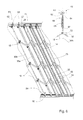
- the numeral 1 denotes in its entirety a collapsible grate comprising a frame 10 and an assembly 13 of first bars 14 and second bars 15 coupled to the frame 10 in a freely sliding fashion along a sliding direction 17 indicated for clarity's sake only in Figure 1.
- the first and second bars 14 and 15 are arranged alternately and each pair formed by a first bar 14 and a second bar 15 positioned consecutively are reciprocally connected by a plurality of first connecting levers 18, in order to form a grid 12.
- This grid 12 can be freely switched between a first open position, in which the first bars 14 and the second bars 15 are spaced apart, and the grid 12 presents its maximum extension in the direction 17, and a second position, in which the first bars 14 and the second bars 15 are close together to minimise the extension of the grid 12 in the direction 17.
- each of the first connecting levers 18 is coupled to the respective first bar 14 and to the respective second bar 15 only by means of turning pairs 19, and that the turning pairs 19 of each first bar 14 and of each second bar 15 are respectively aligned along a respective single axis 3, parallel to the first and second bars 14 and 15.
- this axis 3 is represented with reference to just one bar 14 and one bar 15 only in Figure 2.
- each first bar 14 and each second bar 15 arranged in succession in the grid comprise, respectively, at least one rod 30a and at least one rod 30b, which are coupled together by means of at least one first lever 18.
- each pair of first and second bars 14 and 15 arranged in succession, together with the first levers 18 which connect them only by turning pairs 19, can be interpreted as an articulated quadrilateral, interpreting each rod 30a as the frame of the articulated mechanism, the corresponding first levers 1 8 as the respective rocker levers and the corresponding rod 30b as a connecting rod.
- the grid 12 therefore comprises a plurality of articulated parallelograms arranged in succession and can therefore be defined overall as a structure 4 composed by articulated parallelograms.
- the frame 10 is delimited at the top and bottom by two prismatic guides, 16a and 16b respectively, to which the bars 14 and 15 are coupled in a sliding fashion so that they can freely move along the direction 17, and to make the grid 12 of the grate 1 particularly sturdy and able to resist break-in attempts including those made by applying transverse force to the assembly 13 of the first and second bars 14 and 15.
- each guide 16a and 16b presents a track 28, and in particular the guide 16a is equipped with a concave track 28 for rollers 27 which will be described in more detail below, and the guide 16b with a convex track 28 for a sliding element, and in particular a sliding block 26, which delimits the lower part of each rod 30b of each second bar 15 at one of the two respective end portions 25, and each rod 30a of each first bar 14 at one of the two respective end portions 24.
- a sliding block 26 also delimits the lower part of each corresponding first bar 14 at its respective end 24, and each corresponding second bar 15 at its respective end 25, and can thus also be interpreted as a stop element, and called more simply "stop".
- This stop element may be used to limit or to adjust the displacement of the rods 30b in such a way that the inclination of the first levers 18 can be limited, to allow an easy displacement of the grid 12 from the first, open position to the second, closed position and viceversa.
- the first levers 18 are inclined with respect to the rods 30a, 30b at an angle of 45° (or, equivalently, 135° if the supplementary angle is considered), whereas in the second, closed position of the grid 12 the firs levers 18 lie substantially parallel to the rods 30a, 30b.
- the grid 12 presents the particularity that, while the rods 30a are constantly coupled with the guide 16a and the guide 16b, since they form the frame of an articulated parallelogram, the rods 30b of each bar 15 are designed to translate longitudinally under the thrust of the respective first levers 18 when the grate is switched from and to its open position, being connecting rods of an articulated parallelogram. In this case but not only, due to the particular arrangement of the first levers 18, the rods 30b of each bar 15 are therefore translated upwards when the grate 1 is operated starting from the respective open position. Each free rod 30b is therefore designed to alternately engage or release the respective track 28, which in this case but not only, belongs to the lower guide 16b of the frame 10.
- the grate 1 is therefore particularly easy to operate, since the friction with the guides 16a and 16b is certainly less than it would be if both ends 25 of all the second bars 15 presented the respective sliding block 26 constantly engaged in the respective track 28; on the other hand, the grate 1 is able to perform its function as an obstacle to break-ins only when it is blocked in the completely open position.
- the grate 1 presents its grid 12 with the sliding blocks 26 of the second bars 15 coupled with the respective track 28 only when it is used to effectively resist break-in attempts.
- At least one of the first bars 14 comprises a first elongated box body 32, which externally delimits the corresponding first bar 14, to fully contain the respective turning pairs 19 and to conceal them from view, so that they are not immediately accessible, and also to protect them from atmospheric agents so as to preserve correct functioning over time; at least one of the second bars 15 comprises a second elongated box body 33 which externally delimits the corresponding second bar to fully contain the respective turning pairs 19 for the same reasons given above with reference to the first box body 32. Both the first and second box bodies 32 and 33 are naturally associated with the rods 30a and 30b also to increase the resistance to attempts to cut the respective first and second bars 14 and 15.
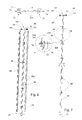
- each turning pair 19 associated with a first or a second bar 14/15 comprises a pin 31 equipped with at least one known cross housing 31b, for simplicity illustrated only in Figure 7 (see, in particular, the enlarged details on the left and on the top left of figure 7), the cross-section of which is greater than the cross-section of the rods 30a and 30b, and is designed to accommodate a rod 30a or a rod 30b of the corresponding first bar 14 or second bar 15.
- the pins 31 are equipped with just one housing 31b for just one rod 30a or just one rod 30b, while in the version shown in Figure 3 there are two housings 31b for two rods 30a or for two rods 30b.
- each pin 31 is associated with at least one coupling element 71, which can be firmly connected to the corresponding pin 31 in a certain axial position to fix the pin 31 in question to each corresponding rod 30a or 30b in an axially rigid fashion by means of an axial blocking element 74, for example a known nut not shown or a grub screw as in Figure 7, designed to determine the stable and releasable connection between the pin 31 and the respective rod 30a/30b, and to precisely locate the fulcrum of the corresponding first levers 18.
- a known screw, an expansion pin or welding point not illustrated are technically equivalent to the grub screw 74. With reference to figure 9, expansion pins can be inserted from only one side of the pin 31, with the advantage of having different diameters.
- the rods 30a/30b are assembled by first inserting one rod (for example 30b) in the respective hole 31b in the pin 31 and blocking the rod with a first pin 310b inserted from the opposite side of the hole 31b.
- the second rod (for example 30a) is then inserted in the respective hole 31a and blocked by a second pin (310a) inserted from the same side of the pin 31 (in some cases the pins are inserted in the same way as screws or grub screws along the axis of the pin).
- Each element 71 is delimited peripherically by an external element 72 associated with the corresponding inner portion of the relative first box body 32/second box body 33.
- this element 71 it is normal for this element 71 to be a nut with a square cross-section, large enough to couple by friction with two known flat opposite sides not illustrated of the first box body 32 or of the second box body 33 in order to respectively generate the transverse blocking of the first box body 32 or the second box body 33, being integral with each respective rod 14. Therefore, with reference to Figure 2, each assembly comprising a pin 31, each element 71, each element 74 and each corresponding rod 30a/30b can be interpreted as a coupling unit 34, designed to keep the first box body 32 prismatically coupled to each corresponding rod 30b.
- each coupling unit 34 comprises at least one blocking element 71, axially mobile and selectively fixable to the respective pin 31 in order to rigidly connect the pin 31 to each corresponding rod 30a/30b.
- each second bar 15 is axially delimited at its end near the track 28 of the guide 16b by a stop 26 longitudinally coupled to the corresponding end 25, and in particular to each rod 30b.
- This stop 26 is designed to engage with the coupling unit 34 to axially fix the corresponding second box body 33 to the corresponding second rod 30b, allowing the movement parallel to the axis 3.
- Every second box body 33 presents a closed cross-section, so as to be bilaterally stable with reference to the coupling units of the corresponding rod 30b and presents at least one slot 39 longitudinally engaged by at least one of the first levers 18.
- Each first box body 32 presents at least one half-casing 54/55 longitudinally shaped internally so that it can be rigidly coupled to each element 71.
- each first box body 32 corresponds to a half-casing 54 and a half-casing 55.
- each first bar 14 and each second bar 15 are equipped with just one rod 30a/30b is fully equivalent from the functional point of view to the embodiment in which there are two rods 30a/30b, also due to the presence of the first and second box bodies 32/33.
- the only difference between the grates of the two embodiments is the different weight and the different ability to resist deformation caused by break-in attempts and cutting, once the first and second box bodies 32/33 have been completely cut, since it is obvious that the force required to bend/cut just one rod is less than the force necessary to bend/cut two.
- the grate 1 is particularly interesting since it can be produced according to a method which, as will be seen, makes it possible to completely pre-assemble each second bar 15 and almost completely each first bar 14 before the installation in the guides 16a and 16b of the frame 10, so as to divide the assembly time into steps that can be carried out simultaneously by different workers.
- the proposed method thus makes it possible to reduce the total assembly time of the grate and consequently to minimise the costs.
- the method comprises the sub-steps of coupling at least one first lever 18 to each pin 31, of coupling at least one element 71 to each pin 31 at the respective housing 31b, of coupling a rod 30b to each element 71 and of axially clamping the pin 31 to the rod 30b by means of an element 74 to form a coupling unit 34, and so on until all the turning pairs 19 are complete.
- the method then foresees the sub-steps of longitudinally coupling in a prismatic fashion a second elongated box body 33 with the first levers 18 arranged parallel to the rods 30b, and of coupling a sliding element 26 and a connecting element 60 which slides at the respective ends 25 to axially block the second box body 33.
- Each first lever 18 is now extracted through the respective longitudinal slot 39, so as to freely swivel with respect to the pin 31, and to free the other end.
- the bar 15 is now complete and ready to be installed in the guides 16a and 16b.
- the semifinished product for the construction of a bar 14 is ready to be prismatically coupled with at least one first box body 32, which must necessarily be divided into the respective C-shaped half-casings 54 and 55, since the rods 30a are no longer longitudinally accessible due to the presence of the first levers 18.
- the coupling can be performed with a relative movement of the rods 30b and the half-casings 54 and 55 along the axis 3, or with a transverse movement to the axis 3 to produce a snap-fit connection. It is now possible to complete the assembly 13 of the first and second bars 14 and 15 held together in the guides 16a and 16b of the frame 10 to complete the grate.
- the version of the grate 1 in Figure 6 shows how the upper end 25 of a rod 30b can be modified to maximize the ability of the grate 1 to resist break-in attempts by maintaining each end of each rod 30b constantly coupled with the guides 16a and 16b of the frame 10, and not just the end 25 of the corresponding second box body 33 of the relative second bar 15 to the frame 10, through the guides 16a and 16b.
- this connecting device 60 presents a slide 62 comprising a pin 31 coupled to each rod 30b by means of a respective housing 31b, and supporting in an end axial position at least one roller 63 substantially identical to the roller 27, by means of an interposed bearing 68.
- the roller 63 is slidingly coupled to the concave track 28 of the guide 16a.
- the device 60 also comprises at least one reduced length rod 64, coaxial to a corresponding rod 30b, and a coupling sleeve 65, with an inner longitudinal guide coaxial to the rod 64 and the rod 30b, and housing the respective free ends 66 and 67.
- the sleeve 65 can be rigidly attached either to the rod 64 or to the rod 30b which it connects, or it can also be left free and resting against the turning pair 19 immediately below, according to the design choice.
- a curtain or fly screen 36 can be fitted to the grate 1, as shown in Figure 5.
- FIG. 4 shows the cross-section of the grate 1 in Figure 3 along a plane transversal to the plane of the grid 12, and represented by the line IV-IV, and that to simplify the representation each pin 31 in Figures 4 and 5 is completely covered by the respective elements 71, and the housings 31b are illustrated by means of a solid rectangular graphic element, deliberately omitting the representation of the cross-sections of the corresponding rods 30a and 30b.
- one end portion, positioned transversally to the direction 17, of at least one of the first and second box bodies 32 and 33 presents a fastening pair 37 for the curtain 36.
- each pair 37 comprises a longitudinal groove 38a into which an elongated body 38b snap fits longitudinally.
- each first and second box body 32 and 33 presents a fastening pair 37 for the curtain 36, and the curtain or fly screen 36 can be selectively closed in an accordion-like fashion.
- the scope of the inventive concept also includes embodiments in which the first levers 18 which connect the first and second consecutive bars 14 and 15 are arranged irregularly, although this means doubling the number of pins 31 since each one will correspond to just one lever 18, and the grid 12 will therefore no longer consist of a plurality of first and second bars 14 and 15 with the respective first levers opposite each other in pairs.
- the scope of the inventive concept also includes the embodiment of the grate 1 in which both ends of the grid 12 comprise a bar 14 and the embodiment of the grate 1 in which the ends of the grid 12 respectively comprise a bar 14 and a bar 15.
- the grate naturally presents an even number of free spaces between the intermediate bars 14 and 15, while in the second case there will be an odd number of free spaces.
Landscapes
- Engineering & Computer Science (AREA)
- Structural Engineering (AREA)
- Architecture (AREA)
- Civil Engineering (AREA)
- Food-Manufacturing Devices (AREA)
- Incineration Of Waste (AREA)
Abstract
Description
- Figure 1 is a schematic perspective view of a first embodiment of a grate according to the present invention;
- Figure 2 is an exploded enlarged-scale schematic perspective view of figure 1 with parts removed for clarity;
- Figure 3 is an exploded schematic perspective view of a variation of figure 2;
- Figure 4 shows a cross-section plan view of figure 3 as represented by the line IV-IV in figure 3;
- Figure 5 shows a variation of figure 4 with evidence of an enlarged detail;
- Figure 6 is a schematic view of a variation of figure 2 showing also a detail in partially sectioned view;
- Figure 7 is an exploded enlarged-scale view of a first detail extracted from figure 3, showing, on the left and on the top left, two further enlarged details;
- Figure 8 is an exploded enlarged-scale view of a second detail extracted from figure 3; and
- Figure 9 shows an alternative construction solution of the further enlarged details shown in figure 7.
Claims (25)
- A grate (1) comprising a first frame (10) and an assembly (13) of first and second bars (14, 15) coupled to the first frame (10) in a freely sliding fashion along a certain direction (17) and positioned alternately to each other; each first bar (14) being connected to at least one consecutive second bar (15) by a plurality of first connecting levers (18) in such a way as to form a grid (12) which can be freely switched between a first open position, in which the first and second bars (14, 15) are spaced apart, and the grid (12) presents its maximum extension in the direction (17), and a second position of minimum longitudinal extension, in which the first and second bars (14, 15) are arranged close together in the direction (17); the grate (1) being characterised in that the first connecting levers (18) are coupled to the respective first and second bars (14, 15) exclusively by means of turning pairs (19); the turning pairs (19) of each first and second bar (14, 15) being respectively aligned with each other along a respective single axis (3).
- A grate (1) according to claim 1, characterised in that each first bar (14) is connected to at least one consecutive second bar (15) by a plurality of first connecting levers (18) in such a way as to maintain the first bars (14) parallel to each other and characterised in that the turning pairs (19) relative to each first and second bar (14, 15) are respectively aligned with each other along a respective single axis (3) substantially parallel to the first and second bars (14, 15).
- A grate according to claim 1 or 2, characterised in that in the grid (12), each first bar (14) and each second bar (15) arranged in succession respectively comprise at least one second frame (30a) and at least one connecting rod (30b) connected together by at least one first lever (18), in such a way that each first lever (18) acts as a rocker arm and that the grid (12) presents, overall, at least one articulated parallelogram structure (4).
- A grate according to claim 3, characterised in that the first frame (10) presents at least one guide (16a)(16b) for the straight-line motion parallel to the direction (17); each first bar (14) presenting at least one first end (24) coupled prismatically to a corresponding guide (16a)(16b) so as to be freely mobile along the direction (17) and designed to resist break-in attempts.
- A grate according to claim 3 or 4, characterised in that each second bar (15) presents at least one second end (25) coupled prismatically to a corresponding guide (16b)(16a) at least when, together with the grid (12), it presents the maximum extension in the direction (17) to resist break-in attempts.
- A grate according to claim 5, characterised in that the first and second bars (14, 15) are equipped at their respective first and second ends (24, 25) with sliding means (26, 60) to couple them to the guide (16a)(16b) in a freely sliding fashion.
- A grate according to claim 6, characterised in that the sliding means (26)(60) are equipped with at least a sliding block (26) and/or a roller (27), and the guide (16a)(16b) comprises a sliding track (28) for the sliding block and/or the roller (27).
- A grate according to claim 7, characterised in that it comprises first elongated box bodies (32) which externally delimit the first bars (14), to completely contain the turning pairs (19); second elongated box bodies (33) which externally delimit the second bars (15), being designed to contain the turning pairs (19); the first and second box bodies (32)(33) being designed to increase the resistance to cutting of the respective first and second bars (14)(15) and to protect the turning pairs (19).
- A grate according to claim 8, characterised in that inside the respective first box body (32) the first bars (14) comprise a second frame (30a); each second frame (30a) comprising, in turn, at least one first rod (30a); inside the respective second box body (33) each of the second bars (15) comprising a connecting rod (30b); each connecting rod (30b) comprises at least one second rod (30b); each turning pair (19) associated with a first bar (14) and a second bar (15) comprising a pin (31) equipped with a transverse housing (31b) respectively accommodating each first rod (30a) of the corresponding first bar (14) in a rigidly axial fashion or each second rod (30b) of the corresponding second bar (15) in a rigidly axial fashion.
- A grate according to claim 8 or 9, characterised in that each pin (31) is associated with coupling means (34) designed to maintain the first box body (32)/second box body (33) prismatically coupled to each corresponding first rod (30a)/second rod (30b).
- A grate according to claim 10, characterised in that the coupling means (34) comprise at least one connecting element (71) that can be clamped with respect to the pin (31) so as to rigidly connect the relative pin (31) to each corresponding first rod (30a) or, selectively, to each corresponding second rod (30b); the connecting element (71) being peripherically delimited by a prismatically shaped surface (72) in order to transversally fix the first box body (32) or, selectively, the second box body (33).
- A grate according to any of the foregoing claims from 8 to 11, characterised in that each second box body (33) presents a closed cross-section so as to bilaterally accommodate the coupling means (34) of each corresponding second rod (30b); and presents at least one longitudinal slit (39) engaged by at least one of the first levers (18).
- A grate according to claim 12, characterised in that each second bar (15) comprises longitudinal stop means (26) designed to engage with the coupling means (34) to axially fix the corresponding second box body (33) to each corresponding second rod (30b).
- A grate according to claim 13, characterised in that each first box body (32) presents at least one longitudinal portion (54, 55) shaped internally in such a way that it can be rigidly coupled to each connecting element (71) transversally to the direction (17).
- A grate according to any of the foregoing claims from 5 to 14, characterised in that each of the second bars (15) presents two second end portions (25), each of which, when in use, is prismatically coupled to a corresponding guide (16b)(16a) at least when the grid (12) is in the position of maximum extension in the direction (17) to maximize the ability of the grid (12) to resist break-in attempts.
- A grate according to claim 15, characterised in that at least one of the two second end portions (25) is equipped with respective connecting means (60) slidingly coupled in the direction (17) to the corresponding guide (16a), to maintain the corresponding connecting rod (30b) coupled to the respective guide (16a).
- A grate according to claim 16, characterised in that for each connecting rod (30b) the connecting means (60) comprise a slide (62) equipped with at least a roller (63) sliding in the guide (16a), at least a third rod (64) coaxial to a second rod (30b) and a sleeve (65) which houses the third rod (64) and the coaxial second rod (30b).
- A grate according to any of the foregoing claims from 8 to 17, characterised in that it comprises at least one curtain (36) and fastening means (37) for the curtain (36); the fastening means (37) being attached to at least two bodies chosen from between the first and second box bodies (32)(33), in such a way that each curtain (36) can be selectively pulled taut to close the first frame (10) and selectively closed in an accordion-like fashion.
- A grate according to claim 18, characterised in that in each of the box bodies (32)(33), the fastening means (37) present a longitudinal groove (38a) into which each curtain (36) snap fits.
- A grate according to claim 19, characterised in that the fastening means (37) comprise an elongated body (38b) which can be longitudinally installed in each groove (38a).
- A grate according to any of the foregoing claims from 18 to 20, characterised in that the curtain (36) comprises a fly screen.
- A method for the production of a grate as described with reference to any of the foregoing claims from 1 to 21; this method presenting a first step of assembling a second bar (15); the first step being characterised in that it comprises the sub-steps of coupling at least a first lever (18) to each one of a plurality of pins (31) in a freely rotating fashion around a longitudinal axis of each pin (31); of coupling each pin (31) to at least one connecting element (71) designed to longitudinally and prismatically couple with a second elongated box body (33); of coupling each pin (31) equipped with the connecting elements (71) to at least one second rod (30b); of longitudinally fixing each pin (31) to each second rod (30b) by means of at least one axial clamping element (74); of coupling each element (71) with the box body (33) by means of a respective closed cross-section; of coupling sliding stop means (26)(60) to the second rod (30b) at its end (25), to axially block the second box body (33); the second box body (33) presenting a longitudinal slit (39) engaged when in use by each first lever (18) which swivels with respect to the pin (31).
- A method according to claim 22, characterised in that it comprises a second step of assembling a first bar (14); the second step comprising the sub-steps of coupling at least a first lever (18) to each one of a plurality of pins (31) in a freely rotating fashion around a longitudinal axis of each pin (31); of coupling each pin (31) to at least one connecting element (71), designed to prismatically couple with a first elongated box body (32)(54, 55) presenting a C-shaped cross-section to each connecting element (71); of coupling at least one first rod (30a) to each pin (31); of coupling sliding stop means (26)(60) to the first rod (30a) at its end (25); of coupling a second elongated box body (32)(54, 55) presenting a C-shaped cross-section to each connecting element (71), in such a way that, when in use, each first lever (18) is free to swivel with respect to the corresponding pin (31) and to completely contain at least one of the ends of the pin (31).
- A method according to claim 23, characterised in that it comprises a third step of coupling each first and each second bar (14)(15) to a prismatic guide (16a)(16b) transverse to the first and second bar (14)(15) by means of the respective sliding stop means (26)(60).
- A method according to claim 24, characterised in that the stop means (26)(60) comprise at least one sliding element (27)(63).
Applications Claiming Priority (2)
| Application Number | Priority Date | Filing Date | Title |
|---|---|---|---|
| ITRA20040011 | 2004-03-05 | ||
| ITRA20040011 ITRA20040011A1 (en) | 2004-03-05 | 2004-03-05 | RAILWAY AND RELATED PRODUCTION METHOD |
Publications (3)
| Publication Number | Publication Date |
|---|---|
| EP1571286A2 true EP1571286A2 (en) | 2005-09-07 |
| EP1571286A3 EP1571286A3 (en) | 2007-08-01 |
| EP1571286B1 EP1571286B1 (en) | 2017-04-05 |
Family
ID=34746728
Family Applications (1)
| Application Number | Title | Priority Date | Filing Date |
|---|---|---|---|
| EP05425126.9A Expired - Lifetime EP1571286B1 (en) | 2004-03-05 | 2005-03-04 | A grate and fabrication method thereof |
Country Status (2)
| Country | Link |
|---|---|
| EP (1) | EP1571286B1 (en) |
| IT (1) | ITRA20040011A1 (en) |
Cited By (1)
| Publication number | Priority date | Publication date | Assignee | Title |
|---|---|---|---|---|
| EP1961907A3 (en) * | 2007-02-23 | 2011-11-02 | TE.SI.FLEX S.r.l. | Grate device which can be opened |
Family Cites Families (6)
| Publication number | Priority date | Publication date | Assignee | Title |
|---|---|---|---|---|
| US1718649A (en) * | 1927-02-24 | 1929-06-25 | See Elevator Company Inc Ab | Collapsible gate |
| US1877829A (en) * | 1928-09-06 | 1932-09-20 | Folding Products Corp | Foldable curtain |
| US4006768A (en) * | 1974-11-22 | 1977-02-08 | Blumcraft Of Pittsburgh | Security screen |
| NL8700590A (en) * | 1987-03-11 | 1988-10-03 | Hendrikus Michael Thimotheus T | COLLAPSIBLE CONSTRUCTION. |
| IT228792Y1 (en) * | 1992-02-17 | 1998-05-21 | Franco Sparaventi | OPENABLE LATTICE, SUITABLE FOR PROTECTING DOORS AND WINDOWS |
| ITRN990005A1 (en) * | 1999-02-19 | 1999-05-19 | Mito S R L | COMPONIBLE UPRIGHT FOR BUILDING STRUCTURES AND RELATED SLIDING AND SAFETY GRATE. |
-
2004
- 2004-03-05 IT ITRA20040011 patent/ITRA20040011A1/en unknown
-
2005
- 2005-03-04 EP EP05425126.9A patent/EP1571286B1/en not_active Expired - Lifetime
Cited By (2)
| Publication number | Priority date | Publication date | Assignee | Title |
|---|---|---|---|---|
| EP1961907A3 (en) * | 2007-02-23 | 2011-11-02 | TE.SI.FLEX S.r.l. | Grate device which can be opened |
| EP2615238A1 (en) * | 2007-02-23 | 2013-07-17 | TE.SI.FLEX S.r.l. | Grate device which can be opened |
Also Published As
| Publication number | Publication date |
|---|---|
| EP1571286A3 (en) | 2007-08-01 |
| ITRA20040011A1 (en) | 2004-06-05 |
| EP1571286B1 (en) | 2017-04-05 |
Similar Documents
| Publication | Publication Date | Title |
|---|---|---|
| RU2166600C1 (en) | Device for door guiding system with flexible blind | |
| EP2157274B1 (en) | Screen device | |
| AU2012287581B2 (en) | Retractable and extendable covering device | |
| EP0753642B1 (en) | Screen apparatus | |
| CZ20022276A3 (en) | Sectional curtain for covering machine parts | |
| EP1571286B1 (en) | A grate and fabrication method thereof | |
| WO2004016893A1 (en) | Improvements relating to multi-fold panel assemblies | |
| KR102182602B1 (en) | Folding door system | |
| KR102432088B1 (en) | Security module and widow installed with the same | |
| US20030101653A1 (en) | Shutter with louvers pivoted by slotted pivot bar extending along an end of the louvers | |
| EP0937852B1 (en) | Operating device for door or window units with hinged wing panels | |
| EP1612356B1 (en) | Hinging device for windows and doors | |
| EP0870896B1 (en) | Mosquito net having improved features | |
| KR102642124B1 (en) | Wrinkled screen door with adjustable tension | |
| DE4115220C2 (en) | ||
| KR101841725B1 (en) | Folding door structure | |
| US5179802A (en) | Louvre structures | |
| EP4234873B1 (en) | Slat control system | |
| KR101869359B1 (en) | Frame assembly of folding door | |
| JP5191807B2 (en) | Telescopic gate | |
| EP0410776A2 (en) | A telescopic door assembly | |
| EP0742337B1 (en) | Sectional door | |
| KR200256852Y1 (en) | Corrugated mosquito net for door | |
| JP2000096957A (en) | Sliding screen unit | |
| EP0298048B1 (en) | Coordinated structure section member assembly, particularly designed for making wing blinds |
Legal Events
| Date | Code | Title | Description |
|---|---|---|---|
| PUAI | Public reference made under article 153(3) epc to a published international application that has entered the european phase |
Free format text: ORIGINAL CODE: 0009012 |
|
| AK | Designated contracting states |
Kind code of ref document: A2 Designated state(s): AT BE BG CH CY CZ DE DK EE ES FI FR GB GR HU IE IS IT LI LT LU MC NL PL PT RO SE SI SK TR |
|
| AX | Request for extension of the european patent |
Extension state: AL BA HR LV MK YU |
|
| PUAL | Search report despatched |
Free format text: ORIGINAL CODE: 0009013 |
|
| AK | Designated contracting states |
Kind code of ref document: A3 Designated state(s): AT BE BG CH CY CZ DE DK EE ES FI FR GB GR HU IE IS IT LI LT LU MC NL PL PT RO SE SI SK TR |
|
| AX | Request for extension of the european patent |
Extension state: AL BA HR LV MK YU |
|
| 17P | Request for examination filed |
Effective date: 20070927 |
|
| AKX | Designation fees paid |
Designated state(s): AT BE BG CH CY CZ DE DK EE ES FI FR GB GR HU IE IS IT LI LT LU MC NL PL PT RO SE SI SK TR |
|
| RAP1 | Party data changed (applicant data changed or rights of an application transferred) |
Owner name: NOBILI, DIEGO |
|
| RIN1 | Information on inventor provided before grant (corrected) |
Inventor name: NOBILI, DIEGO |
|
| 17Q | First examination report despatched |
Effective date: 20160225 |
|
| GRAP | Despatch of communication of intention to grant a patent |
Free format text: ORIGINAL CODE: EPIDOSNIGR1 |
|
| INTG | Intention to grant announced |
Effective date: 20161103 |
|
| GRAS | Grant fee paid |
Free format text: ORIGINAL CODE: EPIDOSNIGR3 |
|
| GRAA | (expected) grant |
Free format text: ORIGINAL CODE: 0009210 |
|
| AK | Designated contracting states |
Kind code of ref document: B1 Designated state(s): AT BE BG CH CY CZ DE DK EE ES FI FR GB GR HU IE IS IT LI LT LU MC NL PL PT RO SE SI SK TR |
|
| REG | Reference to a national code |
Ref country code: GB Ref legal event code: FG4D |
|
| REG | Reference to a national code |
Ref country code: CH Ref legal event code: EP |
|
| REG | Reference to a national code |
Ref country code: AT Ref legal event code: REF Ref document number: 882011 Country of ref document: AT Kind code of ref document: T Effective date: 20170415 |
|
| REG | Reference to a national code |
Ref country code: IE Ref legal event code: FG4D |
|
| REG | Reference to a national code |
Ref country code: DE Ref legal event code: R096 Ref document number: 602005051665 Country of ref document: DE |
|
| REG | Reference to a national code |
Ref country code: NL Ref legal event code: MP Effective date: 20170405 |
|
| REG | Reference to a national code |
Ref country code: LT Ref legal event code: MG4D |
|
| REG | Reference to a national code |
Ref country code: AT Ref legal event code: MK05 Ref document number: 882011 Country of ref document: AT Kind code of ref document: T Effective date: 20170405 |
|
| PG25 | Lapsed in a contracting state [announced via postgrant information from national office to epo] |
Ref country code: NL Free format text: LAPSE BECAUSE OF FAILURE TO SUBMIT A TRANSLATION OF THE DESCRIPTION OR TO PAY THE FEE WITHIN THE PRESCRIBED TIME-LIMIT Effective date: 20170405 |
|
| PG25 | Lapsed in a contracting state [announced via postgrant information from national office to epo] |
Ref country code: LT Free format text: LAPSE BECAUSE OF FAILURE TO SUBMIT A TRANSLATION OF THE DESCRIPTION OR TO PAY THE FEE WITHIN THE PRESCRIBED TIME-LIMIT Effective date: 20170405 Ref country code: GR Free format text: LAPSE BECAUSE OF FAILURE TO SUBMIT A TRANSLATION OF THE DESCRIPTION OR TO PAY THE FEE WITHIN THE PRESCRIBED TIME-LIMIT Effective date: 20170706 Ref country code: AT Free format text: LAPSE BECAUSE OF FAILURE TO SUBMIT A TRANSLATION OF THE DESCRIPTION OR TO PAY THE FEE WITHIN THE PRESCRIBED TIME-LIMIT Effective date: 20170405 Ref country code: ES Free format text: LAPSE BECAUSE OF FAILURE TO SUBMIT A TRANSLATION OF THE DESCRIPTION OR TO PAY THE FEE WITHIN THE PRESCRIBED TIME-LIMIT Effective date: 20170405 Ref country code: FI Free format text: LAPSE BECAUSE OF FAILURE TO SUBMIT A TRANSLATION OF THE DESCRIPTION OR TO PAY THE FEE WITHIN THE PRESCRIBED TIME-LIMIT Effective date: 20170405 |
|
| PG25 | Lapsed in a contracting state [announced via postgrant information from national office to epo] |
Ref country code: PL Free format text: LAPSE BECAUSE OF FAILURE TO SUBMIT A TRANSLATION OF THE DESCRIPTION OR TO PAY THE FEE WITHIN THE PRESCRIBED TIME-LIMIT Effective date: 20170405 Ref country code: SE Free format text: LAPSE BECAUSE OF FAILURE TO SUBMIT A TRANSLATION OF THE DESCRIPTION OR TO PAY THE FEE WITHIN THE PRESCRIBED TIME-LIMIT Effective date: 20170405 Ref country code: BG Free format text: LAPSE BECAUSE OF FAILURE TO SUBMIT A TRANSLATION OF THE DESCRIPTION OR TO PAY THE FEE WITHIN THE PRESCRIBED TIME-LIMIT Effective date: 20170705 Ref country code: PT Free format text: LAPSE BECAUSE OF FAILURE TO SUBMIT A TRANSLATION OF THE DESCRIPTION OR TO PAY THE FEE WITHIN THE PRESCRIBED TIME-LIMIT Effective date: 20170807 Ref country code: IS Free format text: LAPSE BECAUSE OF FAILURE TO SUBMIT A TRANSLATION OF THE DESCRIPTION OR TO PAY THE FEE WITHIN THE PRESCRIBED TIME-LIMIT Effective date: 20170805 |
|
| REG | Reference to a national code |
Ref country code: DE Ref legal event code: R097 Ref document number: 602005051665 Country of ref document: DE |
|
| PG25 | Lapsed in a contracting state [announced via postgrant information from national office to epo] |
Ref country code: EE Free format text: LAPSE BECAUSE OF FAILURE TO SUBMIT A TRANSLATION OF THE DESCRIPTION OR TO PAY THE FEE WITHIN THE PRESCRIBED TIME-LIMIT Effective date: 20170405 Ref country code: DK Free format text: LAPSE BECAUSE OF FAILURE TO SUBMIT A TRANSLATION OF THE DESCRIPTION OR TO PAY THE FEE WITHIN THE PRESCRIBED TIME-LIMIT Effective date: 20170405 Ref country code: RO Free format text: LAPSE BECAUSE OF FAILURE TO SUBMIT A TRANSLATION OF THE DESCRIPTION OR TO PAY THE FEE WITHIN THE PRESCRIBED TIME-LIMIT Effective date: 20170405 Ref country code: CZ Free format text: LAPSE BECAUSE OF FAILURE TO SUBMIT A TRANSLATION OF THE DESCRIPTION OR TO PAY THE FEE WITHIN THE PRESCRIBED TIME-LIMIT Effective date: 20170405 Ref country code: SK Free format text: LAPSE BECAUSE OF FAILURE TO SUBMIT A TRANSLATION OF THE DESCRIPTION OR TO PAY THE FEE WITHIN THE PRESCRIBED TIME-LIMIT Effective date: 20170405 |
|
| PLBE | No opposition filed within time limit |
Free format text: ORIGINAL CODE: 0009261 |
|
| STAA | Information on the status of an ep patent application or granted ep patent |
Free format text: STATUS: NO OPPOSITION FILED WITHIN TIME LIMIT |
|
| 26N | No opposition filed |
Effective date: 20180108 |
|
| PG25 | Lapsed in a contracting state [announced via postgrant information from national office to epo] |
Ref country code: SI Free format text: LAPSE BECAUSE OF FAILURE TO SUBMIT A TRANSLATION OF THE DESCRIPTION OR TO PAY THE FEE WITHIN THE PRESCRIBED TIME-LIMIT Effective date: 20170405 |
|
| REG | Reference to a national code |
Ref country code: DE Ref legal event code: R119 Ref document number: 602005051665 Country of ref document: DE |
|
| REG | Reference to a national code |
Ref country code: CH Ref legal event code: PL |
|
| GBPC | Gb: european patent ceased through non-payment of renewal fee |
Effective date: 20180304 |
|
| PG25 | Lapsed in a contracting state [announced via postgrant information from national office to epo] |
Ref country code: MC Free format text: LAPSE BECAUSE OF FAILURE TO SUBMIT A TRANSLATION OF THE DESCRIPTION OR TO PAY THE FEE WITHIN THE PRESCRIBED TIME-LIMIT Effective date: 20170405 |
|
| REG | Reference to a national code |
Ref country code: BE Ref legal event code: MM Effective date: 20180331 |
|
| REG | Reference to a national code |
Ref country code: IE Ref legal event code: MM4A |
|
| PG25 | Lapsed in a contracting state [announced via postgrant information from national office to epo] |
Ref country code: LU Free format text: LAPSE BECAUSE OF NON-PAYMENT OF DUE FEES Effective date: 20180304 |
|
| PG25 | Lapsed in a contracting state [announced via postgrant information from national office to epo] |
Ref country code: DE Free format text: LAPSE BECAUSE OF NON-PAYMENT OF DUE FEES Effective date: 20181002 Ref country code: IE Free format text: LAPSE BECAUSE OF NON-PAYMENT OF DUE FEES Effective date: 20180304 |
|
| PG25 | Lapsed in a contracting state [announced via postgrant information from national office to epo] |
Ref country code: BE Free format text: LAPSE BECAUSE OF NON-PAYMENT OF DUE FEES Effective date: 20180331 Ref country code: CH Free format text: LAPSE BECAUSE OF NON-PAYMENT OF DUE FEES Effective date: 20180331 Ref country code: GB Free format text: LAPSE BECAUSE OF NON-PAYMENT OF DUE FEES Effective date: 20180304 Ref country code: LI Free format text: LAPSE BECAUSE OF NON-PAYMENT OF DUE FEES Effective date: 20180331 |
|
| PG25 | Lapsed in a contracting state [announced via postgrant information from national office to epo] |
Ref country code: FR Free format text: LAPSE BECAUSE OF NON-PAYMENT OF DUE FEES Effective date: 20180331 |
|
| PG25 | Lapsed in a contracting state [announced via postgrant information from national office to epo] |
Ref country code: TR Free format text: LAPSE BECAUSE OF FAILURE TO SUBMIT A TRANSLATION OF THE DESCRIPTION OR TO PAY THE FEE WITHIN THE PRESCRIBED TIME-LIMIT Effective date: 20170405 |
|
| PGFP | Annual fee paid to national office [announced via postgrant information from national office to epo] |
Ref country code: IT Payment date: 20200310 Year of fee payment: 16 |
|
| PG25 | Lapsed in a contracting state [announced via postgrant information from national office to epo] |
Ref country code: HU Free format text: LAPSE BECAUSE OF FAILURE TO SUBMIT A TRANSLATION OF THE DESCRIPTION OR TO PAY THE FEE WITHIN THE PRESCRIBED TIME-LIMIT; INVALID AB INITIO Effective date: 20050304 |
|
| PG25 | Lapsed in a contracting state [announced via postgrant information from national office to epo] |
Ref country code: CY Free format text: LAPSE BECAUSE OF FAILURE TO SUBMIT A TRANSLATION OF THE DESCRIPTION OR TO PAY THE FEE WITHIN THE PRESCRIBED TIME-LIMIT Effective date: 20170405 |
|
| PG25 | Lapsed in a contracting state [announced via postgrant information from national office to epo] |
Ref country code: IT Free format text: LAPSE BECAUSE OF NON-PAYMENT OF DUE FEES Effective date: 20210304 |