EP1571065A2 - Zahnstangenlenkung für Kraftfahrzeuge - Google Patents
Zahnstangenlenkung für Kraftfahrzeuge Download PDFInfo
- Publication number
- EP1571065A2 EP1571065A2 EP05002858A EP05002858A EP1571065A2 EP 1571065 A2 EP1571065 A2 EP 1571065A2 EP 05002858 A EP05002858 A EP 05002858A EP 05002858 A EP05002858 A EP 05002858A EP 1571065 A2 EP1571065 A2 EP 1571065A2
- Authority
- EP
- European Patent Office
- Prior art keywords
- rack
- pressure piece
- pinion
- pinion steering
- guide roller
- Prior art date
- Legal status (The legal status is an assumption and is not a legal conclusion. Google has not performed a legal analysis and makes no representation as to the accuracy of the status listed.)
- Granted
Links
Images


Classifications
-
- B—PERFORMING OPERATIONS; TRANSPORTING
- B62—LAND VEHICLES FOR TRAVELLING OTHERWISE THAN ON RAILS
- B62D—MOTOR VEHICLES; TRAILERS
- B62D3/00—Steering gears
- B62D3/02—Steering gears mechanical
- B62D3/12—Steering gears mechanical of rack-and-pinion type
- B62D3/123—Steering gears mechanical of rack-and-pinion type characterised by pressure yokes
-
- F—MECHANICAL ENGINEERING; LIGHTING; HEATING; WEAPONS; BLASTING
- F16—ENGINEERING ELEMENTS AND UNITS; GENERAL MEASURES FOR PRODUCING AND MAINTAINING EFFECTIVE FUNCTIONING OF MACHINES OR INSTALLATIONS; THERMAL INSULATION IN GENERAL
- F16H—GEARING
- F16H55/00—Elements with teeth or friction surfaces for conveying motion; Worms, pulleys or sheaves for gearing mechanisms
- F16H55/02—Toothed members; Worms
- F16H55/26—Racks
- F16H55/28—Special devices for taking up backlash
- F16H55/283—Special devices for taking up backlash using pressure yokes
-
- F—MECHANICAL ENGINEERING; LIGHTING; HEATING; WEAPONS; BLASTING
- F16—ENGINEERING ELEMENTS AND UNITS; GENERAL MEASURES FOR PRODUCING AND MAINTAINING EFFECTIVE FUNCTIONING OF MACHINES OR INSTALLATIONS; THERMAL INSULATION IN GENERAL
- F16H—GEARING
- F16H55/00—Elements with teeth or friction surfaces for conveying motion; Worms, pulleys or sheaves for gearing mechanisms
- F16H55/02—Toothed members; Worms
- F16H55/26—Racks
- F16H55/28—Special devices for taking up backlash
- F16H55/283—Special devices for taking up backlash using pressure yokes
- F16H55/285—Special devices for taking up backlash using pressure yokes with rollers or balls to reduce friction
-
- Y—GENERAL TAGGING OF NEW TECHNOLOGICAL DEVELOPMENTS; GENERAL TAGGING OF CROSS-SECTIONAL TECHNOLOGIES SPANNING OVER SEVERAL SECTIONS OF THE IPC; TECHNICAL SUBJECTS COVERED BY FORMER USPC CROSS-REFERENCE ART COLLECTIONS [XRACs] AND DIGESTS
- Y10—TECHNICAL SUBJECTS COVERED BY FORMER USPC
- Y10T—TECHNICAL SUBJECTS COVERED BY FORMER US CLASSIFICATION
- Y10T74/00—Machine element or mechanism
- Y10T74/20—Control lever and linkage systems
- Y10T74/20396—Hand operated
Definitions
- the invention relates to a rack and pinion steering for a motor vehicle, with a Steering housing, in which a rack is mounted longitudinally displaceable, as well a meshing with the rack pinion and a pressure piece on the a side of the rack opposite an engagement side with the pinion is arranged and biased by a spring against the rack is, wherein the pressure piece in its interior one of the contour of the rack adapted, rotatable guide roller having a support surface, at the rests the rack with a corresponding support surface, wherein the Wings are arranged to each other so that a rotation of the Rack is prevented in the circumferential direction.
- Such rack and pinion steering systems are known from the prior art for a long time previously known.
- the rack is in the longitudinal direction slidably guided in a steering box.
- a rotatable in the steering housing stored pinion engages the toothing of the rack and causes at Rotation of the rotatably connected to the pinion steering column, the lateral displacement the rack, in turn, via tie rods and stub axles leads to a pivoting of the steered wheels of the motor vehicle.
- Engage the pinion in the rack is held backlash by one opposite the pinion on the rack fitting pressure piece under bias push the rack against the pinion.
- the pressure piece must be for one can transmit the required contact pressure and the other one Provide bearing surface, which is the displacement of the rack on the pressure piece no significant frictional forces and no significant wear causes.
- the rack is trying to be over its axial length in To twist the circumferential direction. This is an attempt to prevent this by the wings of leadership and rack so arranged to each other are that they oppose a twisting of the rack.
- Such a rack and pinion steering is known from DE 82 03 943 U.
- the rack has two wings on, which are inclined symmetrically against the toothing plane.
- to Rack and pinion steering continues to be a leader in a pressure piece is arranged and also has two wings.
- the wings of the Rack are made by cutting material removal in the initial state generated round rack.
- the wings of the leadership are by two arranged in the pressure piece outer rings of a ball bearing, whose Lateral surfaces forming the wings, also symmetrically inclined the toothing plane are arranged. It is obvious, that by such a position of the wings of the rack and guide roller a rotation of the rack is prevented in the circumferential direction.
- this object is achieved by the characterizing part of Claim 1 in conjunction with its preamble solved in that the Supporting surface as at least one recess located within the rack is trained.
- the Supporting surface as at least one recess located within the rack is trained.
- the bearing surface of the Rack should be semicircular or V-shaped. Both variants stand equally side by side and can be based on Their uncomplicated geometric cross-sectional shape also simpler Insert the way into the rack.
- Needle roller bearing is rotatably mounted in the pressure piece. Needle roller bearings are standardized Purchased parts, which are purchased inexpensively in a wide variety of dimensions to let. In addition, they are able to absorb high radial forces and ensure a noiseless leadership role.
- the Pressure piece to be made of a plastic material that is injection molded inexpensive manufacture in different design variants.
- a Such training of the pressure piece has additional damping properties out, which have a positive effect on the steering comfort.
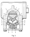
- FIG. 1 shows a housing 1 in which a pinion 2, which merges into a steering shaft 3, is mounted.
- a pinion 2 which merges into a steering shaft 3, is mounted.
- a pressure piece 5 is arranged, which is the from the pinion 2 on the rack 4 transmitted force is substantially supported.
- the pressure piece 5 is in an unspecified receiving bore of the housing 1 housed. It is of a between the pressure piece 5 and a rigidly connected to the housing 1 cover 6 arranged spring. 7 biased in the direction of the rack 4.
- a guide roller 8 is housed, consisting of two as deep groove ball bearings trained rolling bearings 9 is made, each on a support shaft 10 are held.
- the support shafts 10 and thus the bearings 9 are under arranged at a certain angle to the toothing plane, so that the inclined bearing outer rings of the bearings 9 with their wings 12th abut the designated 11 wings of the rack 4. It lies obvious that the rack 4 do not move in the circumferential direction can, if a torque, for example by a ball screw, is applied.
- FIG. 1 shows an arrangement of a pressure piece 14 according to the invention and a rack 13, wherein according to the known state of Technique the rack 13 on its side facing away from the pressure member 14 side a toothing 13.1 is provided, in which engages a pinion, not shown.
- the rack 13 On its side opposite the teeth 13.1 side, the rack 13 a recess 13.2, which in the exemplary embodiment V-shaped is designed so that two wings 13.3, 13.4 are formed, which are symmetrical are inclined to the toothing plane 13.1.
- a guide roller 15 rotatably supported via a needle bearing 17.
- the guide roller 5 is formed as a rotationally symmetrical body, the also inclined symmetrically to its axis of rotation 15.1 Has wings 15.2, 15.3.
- the guide roller 15 is Seen in longitudinal section like a house, with the roof in the V-shaped Recess 13.2 of the rack 13 engages.
- the axial needle bearing 17 consists of guided in a cage 17.1 bearing needles 17.2, of a Needle sleeve 17.3 are received, which with radially inwardly directed Borden 17.3.1 is provided.
- the needle bearing 17 is still one each Thrust washer 18, which are arranged on the right and left side and the support serve axial forces.
- the pressure piece 19 shown in FIG. 2 differs from that in FIG. 1 in that it is made of a plastic.
- the pressure piece 19 at least over a portion of his Enclosed surface of a metallic sleeve 20, wherein the plastic body has a radially outward projection 19.1, on the sleeve 20 is placed.
- Another significant difference lies in that the guide roller 15 for absorbing axial forces occurring is supported by a thrust bearing 21, the guided in a cage 21.1 Bearing needles 21.2 between the two associated pulleys 21.3, Roll off 21.4, wherein the running disk 21.3 firmly in the plastic body of the pressure piece 19 is arranged and the associated other running disk 21.4 with the Guide roller 15 rotates.
Landscapes
- Engineering & Computer Science (AREA)
- General Engineering & Computer Science (AREA)
- Mechanical Engineering (AREA)
- Chemical & Material Sciences (AREA)
- Combustion & Propulsion (AREA)
- Transportation (AREA)
- Transmission Devices (AREA)
- Gears, Cams (AREA)
Abstract
Description
- Figur 1 und 2
- einen Längsschnitt durch ein erfindungsgemäß ausgebildetes Druckstück mit Zahnstange und
- Figur 3
- einen Längsschnitt durch ein Druckstück mit Zahnstange nach dem bisherigen Stand der Technik
- kostengünstige Herstellung und Montage,
- geringe Verlustreibung und hohe Laufruhe,
- sichere Aufnahme von axialen- und radialen Kräften und von einwirkenden Drehmomenten,
- hohe Tragfähigkeit.
- 1
- Gehäuse
- 2
- Ritzel
- 3
- Lenkspindel
- 4
- Zahnstange
- 5
- Druckstück
- 6
- Deckel
- 7
- Feder
- 8
- Führungsrolle
- 9
- Wälzlager
- 10
- Tragachse
- 11
- Tragfläche
- 12
- Tragfläche
- 13
- Zahnstange
- 13.1
- Verzahnung
- 13.2
- Ausnehmung
- 13.3
- Tragfläche
- 13.4
- Tragfläche
- 14
- Druckstück
- 15
- Führungsrolle
- 15.1
- Rotationsachse
- 15.2
- Tragfläche
- 15.3
- Tragfläche
- 16
- Tragachse
- 17
- Nadellager
- 16.1
- Käfig
- 16.2
- Lagernadel
- 16.3
- Nadelhülse
- 16.3.1
- Bord
- 17
- Anlaufscheibe
- 18
- Druckstück
- 18.1
- Vorsprung
- 19
- Hülse
- 20
- Axiallager
- 20.1
- Käfig
- 20.2
- Lagernadel
- 20.3
- Laufscheibe
- 20.4
- Laufscheibe
Claims (9)
- Zahnstangenlenkung für ein Kraftfahrzeug, mit einem Lenkgehäuse (1), in dem eine Zahnstange (13) längsverschieblich gelagert ist, sowie einem mit der Zahnstange (13) kämmenden Ritzel (2) und einem Druckstück (14, 19), das auf einer einer Eingriffsseite mit dem Ritzel (2) gegenüberliegenden Seite der Zahnstange (13) angeordnet ist und mit Hilfe einer Feder (7) gegen die Zahnstange (13) vorgespannt ist, wobei das Druckstück in (14,19) seinem Inneren eine der Kontur der Zahnstange (13) angepaßte, drehbare Führungsrolle (15) mit einer Tragfläche aufweist, an der die Zahnstange (13) mit einer korrespondierenden Tragfläche anliegt, wobei die Tragflächen so zueinander angeordnet sind, dass ein Verdrehen der Zahnstange (13) in Umfangsrichtung verhindert ist, dadurch gekennzeichnet, dass die Tragfläche als wenigstens eine innerhalb der Zahnstange (13) liegende Ausnehmung (13.2) ausgebildet ist.
- Zahnstangelenkung nach Anspruch 1, dadurch gekennzeichnet, dass die Ausnehmung (13.2) der Zahnstange (13) halbkreisförmig ausgebildet ist.
- Zahnstangelenkung nach Anspruch 1, dadurch gekennzeichnet, dass die Ausnehmung (13.2) der Zahnstange (13) V-förmig ausgebildet ist.
- Zahnstangenlenkung nach Anspruch 1, dadurch gekennzeichnet, dass die Führungsrolle (15) über ein von einer Tragachse (16) aufgenommenes Nadellager (17) im Druckstück (14) drehbar gelagert ist.
- Zahnstangenlenkung nach Anspruch 4, dadurch gekennzeichnet, dass die Führungsrolle (15) beidseitig in axialer Richtung von je einer Anlaufscheibe (18) umgeben ist.
- Zahnstangenlenkung nach Anspruch 4, dadurch gekennzeichnet, dass die Führungsrolle (15) beidseitig in axialer Richtung von je einem Axiallager (21) umgeben ist.
- Zahnstangenlenkung nach Anspruch 1, dadurch gekennzeichnet, dass das Druckstück (19) aus einem Kunststoff hergestellt ist.
- Zahnstangenlenkung nach Anspruch 7, dadurch gekennzeichnet, dass das Druckstück (19) wenigstens über einen Teilbereich seiner Mantelfläche von einer metallischen Hülse (20) aufgenommen ist.
- Zahnstangenlenkung nach Anspruch 8, dadurch gekennzeichnet, dass das Druckstück (19) ein die metallische Hülse (20) in radialer Richtung überragenden Vorsprung (19.1) aufweist.
Applications Claiming Priority (2)
| Application Number | Priority Date | Filing Date | Title |
|---|---|---|---|
| DE102004010821A DE102004010821A1 (de) | 2004-03-05 | 2004-03-05 | Zahnstangenlenkung |
| DE102004010821 | 2004-03-05 |
Publications (3)
| Publication Number | Publication Date |
|---|---|
| EP1571065A2 true EP1571065A2 (de) | 2005-09-07 |
| EP1571065A3 EP1571065A3 (de) | 2006-09-13 |
| EP1571065B1 EP1571065B1 (de) | 2007-05-02 |
Family
ID=34745406
Family Applications (1)
| Application Number | Title | Priority Date | Filing Date |
|---|---|---|---|
| EP05002858A Expired - Lifetime EP1571065B1 (de) | 2004-03-05 | 2005-02-11 | Zahnstangenlenkung für Kraftfahrzeuge |
Country Status (3)
| Country | Link |
|---|---|
| US (1) | US20050193849A1 (de) |
| EP (1) | EP1571065B1 (de) |
| DE (2) | DE102004010821A1 (de) |
Families Citing this family (1)
| Publication number | Priority date | Publication date | Assignee | Title |
|---|---|---|---|---|
| DE102006043578A1 (de) * | 2006-09-16 | 2008-03-27 | Zf Lenksysteme Gmbh | Vorrichtung zum Andrücken einer Zahnstange an ein mit der Zahnstange in Eingriff stehendes Ritzel |
Family Cites Families (23)
| Publication number | Priority date | Publication date | Assignee | Title |
|---|---|---|---|---|
| GB1168191A (en) * | 1968-04-29 | 1969-10-22 | Cam Gears Ltd | Improvements in or relating to Rack and Pinion Assemblies |
| FR2180157A5 (de) * | 1972-04-10 | 1973-11-23 | Gemmer France | |
| GB2036240B (en) * | 1978-11-27 | 1982-12-15 | Cam Gears Ltd | Variable ratio rack and pinion gear |
| DE2913641C2 (de) * | 1979-04-05 | 1985-11-21 | INA Wälzlager Schaeffler KG, 8522 Herzogenaurach | Zahnstangenlenkung für Kraftfahrzeuge |
| DE8203943U1 (de) * | 1981-02-24 | 1982-07-01 | RIV-SKF Officine di Villar Perosa S.p.A., 10123 Torino | Lenkgetriebe fuer kraftfahrzeuge mit einem gegendruckelement fuer die zahnstange |
| KR900002221B1 (ko) * | 1984-07-09 | 1990-04-06 | 미쯔비시지도오샤고오교오 가부시기가이샤 | 조타기어장치 |
| IT8453881V0 (it) * | 1984-10-02 | 1984-10-02 | Riv Officine Di Villar Perosa | Scatola sterzo per un autoveicolo |
| US5058448A (en) * | 1988-10-27 | 1991-10-22 | Koyo Seiko Co., Ltd. | Rack and pinion steering device |
| IT1245511B (it) * | 1991-02-15 | 1994-09-29 | Gate Spa | Cavo di trasmissione flessibile dentato, procedimento per la sua fabbricazione e meccanismo di trasmissione comprendente tale cavo |
| US5622085A (en) * | 1995-08-15 | 1997-04-22 | Trw Inc. | Rack and pinion steering gear with improved yoke |
| DE19726697A1 (de) * | 1997-06-24 | 1999-01-07 | Zahnradfabrik Friedrichshafen | Verfahren zum Herstellen einer Zahnstange |
| US5983742A (en) * | 1998-02-05 | 1999-11-16 | Oiles America Corporation | Rack and pinion steering device with split roller rack bar support |
| DE19936539B4 (de) * | 1999-08-03 | 2005-10-27 | Daimlerchrysler Ag | Zahnstangengetriebe einer Zahnstangenlenkung |
| US6408708B1 (en) * | 2000-08-10 | 2002-06-25 | Trw Inc. | Rack and pinion steering gear with low friction yoke assembly |
| US6467366B1 (en) * | 2000-10-26 | 2002-10-22 | Trw Inc. | Yoke bearing assembly for hydraulic power assist rack and pinion power steering system |
| US20020084136A1 (en) * | 2000-12-29 | 2002-07-04 | Fowlkes Edward Taylor | Power steering system with roller yoke |
| US6736021B2 (en) * | 2001-04-20 | 2004-05-18 | Trw Inc. | Rack and pinion steering gear with low friction roller yoke design |
| US6619420B1 (en) * | 2002-04-16 | 2003-09-16 | Trw Inc. | Rack and pinion steering gear with hydraulic yoke assembly |
| DE10225718A1 (de) * | 2002-06-11 | 2004-01-08 | Zf Lenksysteme Gmbh | Zahnstangenlenkung |
| JP2004034829A (ja) * | 2002-07-03 | 2004-02-05 | Nsk Ltd | ステアリング装置及びラック軸の製造方法 |
| JP2004075000A (ja) * | 2002-08-22 | 2004-03-11 | Nsk Ltd | ステアリング装置 |
| US7281444B1 (en) * | 2003-12-05 | 2007-10-16 | Trw Automotive U.S. Llc | Rack and pinion gear yoke assembly |
| DE102004010819A1 (de) * | 2004-03-05 | 2005-09-22 | Ina-Schaeffler Kg | Zahnstangenlenkung |
-
2004
- 2004-03-05 DE DE102004010821A patent/DE102004010821A1/de not_active Withdrawn
-
2005
- 2005-02-11 EP EP05002858A patent/EP1571065B1/de not_active Expired - Lifetime
- 2005-02-11 DE DE502005000631T patent/DE502005000631D1/de not_active Expired - Fee Related
- 2005-03-07 US US11/074,216 patent/US20050193849A1/en not_active Abandoned
Also Published As
| Publication number | Publication date |
|---|---|
| DE102004010821A1 (de) | 2005-09-22 |
| DE502005000631D1 (de) | 2007-06-14 |
| US20050193849A1 (en) | 2005-09-08 |
| EP1571065A3 (de) | 2006-09-13 |
| EP1571065B1 (de) | 2007-05-02 |
Similar Documents
| Publication | Publication Date | Title |
|---|---|---|
| DE19839481C2 (de) | Verteilergetriebe für ein Kraftfahrzeug | |
| EP0770538B1 (de) | Zahnstangengetriebe | |
| EP2233381B1 (de) | Kostengünstiges Zahnstangenlenkgetriebe | |
| DE112016002670T5 (de) | Getriebeanordnung für elektrische Servolenkung | |
| DE112015001038T5 (de) | Hilfskraft-Lenkvorrichtung und Verfahren zur Herstellung einer Kugel-Umlauf-Spindel für eine Hilfskraft-Lenkvorrichtung | |
| DE102016007541A1 (de) | Kugelgewindetrieb einer elektromechanischen Servolenkung mit integriertem Schrägkugellager | |
| EP2091801B1 (de) | Zahnstangenlenkung | |
| DE102004020851B4 (de) | Lagerung einer Welle | |
| DE102018130734A1 (de) | Kugelmutterbaugruppe für eine servolenkungbaugruppeeines fahrzeugs | |
| EP3538418B1 (de) | Festlager und lenkgetriebe | |
| DE3022020C2 (de) | Axiale Kraftübertragungs-Einrichtung für ein Stirnradgetriebe | |
| DE102012108423A1 (de) | Zahnstange für ein Lenksystem eines Kraftfahrzeugs, Lenkgetriebe und Druckstück | |
| EP1571066A2 (de) | Druckstück für Kraftfahrzeug-Zahnstangenlenkung | |
| DE2913641A1 (de) | Lagerung der zahnstange einer zahnstangenlenkung fuer kraftfahrzeuge | |
| DE4227662A1 (de) | Radialwälzlager | |
| WO2004020856A1 (de) | Lagerung einer welle | |
| DE102008045848A1 (de) | Planetengetriebe | |
| DE69611900T2 (de) | Differentialgetriebe und Methode zur Herstellung der dafür verwendeten Nockenscheiben | |
| EP1571065B1 (de) | Zahnstangenlenkung für Kraftfahrzeuge | |
| DE10314358B4 (de) | Zahnstangenlenkung | |
| DE102006043578A1 (de) | Vorrichtung zum Andrücken einer Zahnstange an ein mit der Zahnstange in Eingriff stehendes Ritzel | |
| DE102005046301A1 (de) | Verschiebeeinheit und Gelenkwelle mit einer Verschiebeeinheit | |
| DE102009028031A1 (de) | Druckstück zum Andrücken einer Zahnstange | |
| EP1577192A2 (de) | Druckstück für Kraftfahrzeug-Zahnstangenlenkung | |
| EP3691957B1 (de) | Elektromechanische servolenkung mit schraubradgetriebe und einer kompensationseinrichtung zur abstützung eines loslagers am getriebegehäuse |
Legal Events
| Date | Code | Title | Description |
|---|---|---|---|
| PUAI | Public reference made under article 153(3) epc to a published international application that has entered the european phase |
Free format text: ORIGINAL CODE: 0009012 |
|
| 17P | Request for examination filed |
Effective date: 20050211 |
|
| AK | Designated contracting states |
Kind code of ref document: A2 Designated state(s): AT BE BG CH CY CZ DE DK EE ES FI FR GB GR HU IE IS IT LI LT LU MC NL PL PT RO SE SI SK TR |
|
| AX | Request for extension of the european patent |
Extension state: AL BA HR LV MK YU |
|
| RAP1 | Party data changed (applicant data changed or rights of an application transferred) |
Owner name: SCHAEFFLER KG |
|
| PUAL | Search report despatched |
Free format text: ORIGINAL CODE: 0009013 |
|
| AK | Designated contracting states |
Kind code of ref document: A3 Designated state(s): AT BE BG CH CY CZ DE DK EE ES FI FR GB GR HU IE IS IT LI LT LU MC NL PL PT RO SE SI SK TR |
|
| AX | Request for extension of the european patent |
Extension state: AL BA HR LV MK YU |
|
| GRAP | Despatch of communication of intention to grant a patent |
Free format text: ORIGINAL CODE: EPIDOSNIGR1 |
|
| GRAS | Grant fee paid |
Free format text: ORIGINAL CODE: EPIDOSNIGR3 |
|
| GRAA | (expected) grant |
Free format text: ORIGINAL CODE: 0009210 |
|
| AK | Designated contracting states |
Kind code of ref document: B1 Designated state(s): DE FR GB IT |
|
| REG | Reference to a national code |
Ref country code: GB Ref legal event code: FG4D Free format text: NOT ENGLISH |
|
| AKX | Designation fees paid |
Designated state(s): DE FR GB IT |
|
| REF | Corresponds to: |
Ref document number: 502005000631 Country of ref document: DE Date of ref document: 20070614 Kind code of ref document: P |
|
| GBT | Gb: translation of ep patent filed (gb section 77(6)(a)/1977) |
Effective date: 20070627 |
|
| ET | Fr: translation filed | ||
| PLBE | No opposition filed within time limit |
Free format text: ORIGINAL CODE: 0009261 |
|
| STAA | Information on the status of an ep patent application or granted ep patent |
Free format text: STATUS: NO OPPOSITION FILED WITHIN TIME LIMIT |
|
| 26N | No opposition filed |
Effective date: 20080205 |
|
| PGFP | Annual fee paid to national office [announced via postgrant information from national office to epo] |
Ref country code: DE Payment date: 20080207 Year of fee payment: 4 |
|
| PGFP | Annual fee paid to national office [announced via postgrant information from national office to epo] |
Ref country code: FR Payment date: 20080208 Year of fee payment: 4 |
|
| GBPC | Gb: european patent ceased through non-payment of renewal fee |
Effective date: 20090211 |
|
| REG | Reference to a national code |
Ref country code: FR Ref legal event code: ST Effective date: 20091030 |
|
| PG25 | Lapsed in a contracting state [announced via postgrant information from national office to epo] |
Ref country code: DE Free format text: LAPSE BECAUSE OF NON-PAYMENT OF DUE FEES Effective date: 20090901 |
|
| PG25 | Lapsed in a contracting state [announced via postgrant information from national office to epo] |
Ref country code: GB Free format text: LAPSE BECAUSE OF NON-PAYMENT OF DUE FEES Effective date: 20090211 Ref country code: FR Free format text: LAPSE BECAUSE OF NON-PAYMENT OF DUE FEES Effective date: 20090302 |
|
| PGFP | Annual fee paid to national office [announced via postgrant information from national office to epo] |
Ref country code: IT Payment date: 20080228 Year of fee payment: 4 |
|
| P01 | Opt-out of the competence of the unified patent court (upc) registered |
Effective date: 20230522 |