EP1571017A1 - Cooling device for construction machines - Google Patents
Cooling device for construction machines Download PDFInfo
- Publication number
- EP1571017A1 EP1571017A1 EP03813290A EP03813290A EP1571017A1 EP 1571017 A1 EP1571017 A1 EP 1571017A1 EP 03813290 A EP03813290 A EP 03813290A EP 03813290 A EP03813290 A EP 03813290A EP 1571017 A1 EP1571017 A1 EP 1571017A1
- Authority
- EP
- European Patent Office
- Prior art keywords
- radiator
- cooling
- air conditioner
- oil cooler
- cooler
- Prior art date
- Legal status (The legal status is an assumption and is not a legal conclusion. Google has not performed a legal analysis and makes no representation as to the accuracy of the status listed.)
- Withdrawn
Links
Images







Classifications
-
- B—PERFORMING OPERATIONS; TRANSPORTING
- B60—VEHICLES IN GENERAL
- B60H—ARRANGEMENTS OF HEATING, COOLING, VENTILATING OR OTHER AIR-TREATING DEVICES SPECIALLY ADAPTED FOR PASSENGER OR GOODS SPACES OF VEHICLES
- B60H1/00—Heating, cooling or ventilating devices
- B60H1/00357—Air-conditioning arrangements specially adapted for particular vehicles
- B60H1/00378—Air-conditioning arrangements specially adapted for particular vehicles for tractor or load vehicle cabins
-
- E—FIXED CONSTRUCTIONS
- E02—HYDRAULIC ENGINEERING; FOUNDATIONS; SOIL SHIFTING
- E02F—DREDGING; SOIL-SHIFTING
- E02F9/00—Component parts of dredgers or soil-shifting machines, not restricted to one of the kinds covered by groups E02F3/00 - E02F7/00
- E02F9/08—Superstructures; Supports for superstructures
- E02F9/0858—Arrangement of component parts installed on superstructures not otherwise provided for, e.g. electric components, fenders, air-conditioning units
-
- E—FIXED CONSTRUCTIONS
- E02—HYDRAULIC ENGINEERING; FOUNDATIONS; SOIL SHIFTING
- E02F—DREDGING; SOIL-SHIFTING
- E02F9/00—Component parts of dredgers or soil-shifting machines, not restricted to one of the kinds covered by groups E02F3/00 - E02F7/00
- E02F9/08—Superstructures; Supports for superstructures
- E02F9/0858—Arrangement of component parts installed on superstructures not otherwise provided for, e.g. electric components, fenders, air-conditioning units
- E02F9/0866—Engine compartment, e.g. heat exchangers, exhaust filters, cooling devices, silencers, mufflers, position of hydraulic pumps in the engine compartment
Definitions
- the present invention relates to a cooling device in a construction machine such as a hydraulic shovel.
- a construction machine such as a hydraulic shovel is provided with a cooling device such as a radiator for cooling an engine and an oil cooler for cooling hydraulic fluid.
- the radiator and oil cooler are generally designed to be cooled with cooling air flowing thereto by rotation of a cooling fan.
- the oil cooler and the radiator are arranged to be superposed back and forth against the flow of the cooling air (Back To Back (BTB) method) or are arranged to be adjacent to each other from side to side (Side By Side (SBS) Method).
- BTB Back To Back
- SBS Side
- an air-conditioning device air conditioners
- a construction machine has been known structured such that an air conditioner capacitor is provided at the front side of the oil cooler or radiator so that the cooling fan for cooling the oil cooler and/or the radiator can also cool the air conditioner capacitor (for example, see Fig. 1 of Japanese Patent Publication No. 3223164).
- the air conditioner capacitor is fixed to the front face side of the oil cooler via a fitting, when maintenance such as inspection and repair of the radiator and/or the oil cooler is performed, the air conditioner capacitor arranged on the front face side must be removed, this is troublesome and causes a reduction in workability.
- the present invention has been made in view of the above present condition for the purpose of solving these problems.
- the air conditioner capacitor is structured to change the postures between a cooling posture in which the air conditioner capacitor is arranged in parallel with another cooling device and an open posture in which the front side or the rear side of another cooling device is exposed.
- the air conditioner capacitor and the turbocharger cooler are arranged at the front side or at the rear side of an oil cooler and/or a radiator against the flow of the cooling air such that the air conditioner capacitor and the turbocharger cooler are structured to change the postures between the cooling posture in which the air conditioner capacitor and the turbocharger cooler are arranged in parallel with the oil cooler and/or the radiator and an open posture in which the front side or the rear side of the oil cooler and/or the radiator is exposed.
- the air conditioner capacitor and the turbocharger cooler may also be arranged at the front side or at the rear side of an oil cooler and/or a radiator against the flow of the cooling air such that the air conditioner capacitor is structured to change the postures between the cooling posture in which the air conditioner capacitor is arranged in parallel with the oil cooler and/or the radiator and an open posture in which the front side or the rear side of the oil cooler and/or the radiator is exposed.
- the above-described configuration can be adapted, in a case where the oil cooler and the radiator are arranged adjacent to each other from side to side against the flow of the cooling air and in a case where the oil cooler and the radiator are arranged to be superposed back and forth against the flow of the cooling air, however, in a case where the oil cooler and the radiator are arranged to be superposed back and forth against the flow of the cooling air, the air conditioner capacitor is structured to change the postures between the cooling posture in which the oil cooler is arranged in parallel with the radiator and an open posture in which the front side or the rear side of the radiator is exposed, thereby further contributing to improvements in maintenance.
- the air conditioner capacitor and/or the turbocharger cooler is/are swingably supported by the upper part of the radiator and/or the oil cooler so as to be swing up and down, or the air conditioner capacitor and/or the turbocharger cooler is/are swingably supported by the left and right sides of the radiator or the oil cooler so as to swing back and forth, thereby allowing the turbocharger cooler and/or the air conditioner capacitor to change the postures between the cooling posture and the open posture.
- a pipe connected to the air conditioner capacitor and/or the turbocharger cooler can be deformed in accordance with the posture change of the air conditioner capacitor and/or the turbocharger cooler, thereby preventing the pipe from being deteriorated due to the posture change of the turbocharger cooler and/or the air conditioner capacitor.
- the reference numeral 1 denotes a hydraulic shovel.
- the hydraulic shovel 1 is composed of a crawler-type lower structure 2, an upper structure 3 rotatably supported by the lower structure 2; and a front attachment 4 attached to the upper structure 3.
- the upper structure 3 also includes a cab 5 and a counterweight 6 or the like as well as various devices and units such as an engine 7 as a source of power, cooling devices such as a radiator 8, an oil cooler 9, an air conditioner capacitor 10, and a turbocharger cooler 11 which will be described later, a hydraulic pump and a valve device (not shown) .
- the radiator 8 is a cooling device for cooling the engine 7.
- the oil cooler 9 is a cooling device for cooling hydraulic fluid and the air conditioner capacitor 10 is a cooling device for cooling and liquefying the cooling medium for cooling.
- the turbocharger cooler 11 is a cooling device for cooling air compressed by the turbocharger 12.
- the radiator 8 is placed at the closest position to the cooling fan (i.e., the most downstream side against the flow of the cooling air) and at the front side of the radiator 8 (upstream side against the flow of the cooling air), the turbocharger cooler 11 is positioned in the upward direction and the oil cooler 9 and the air conditioner capacitor 10 are positioned in the lower direction.
- the oil cooler 9 is swingably supported by one side of the left side or the right side of the radiator 8 via the upper and lower hinge members 13 so as to swing back and forth, whereby enabling it to change the postures between a cooling posture in which the oil cooler 9 is arranged in parallel with the radiator 8 so as to be cooled by the cooling fan and an open posture in which the oil cooler 9 is swung to the front side so that the lower half of the front face of the radiator 8 is exposed.
- the air conditioner capacitor 10 is attached to the front face of the oil cooler 9 via the left and right fitting brackets 14 and is structured to change the postures integrally with the oil cooler 9.
- the turbocharger cooler 11 is swingably supported by the upper front face of the radiator 8 via the left and right hinge members 15 so as to swing up and down and is structured to change the postures between a cooling posture in which the turbocharger cooler 11 is arranged in parallel with the radiator 8 so as to be cooled by the cooling fan and an open posture in which the turbocharger cooler 11 is swung from the cooling posture in the upward direction so that the lower half of the front face of the radiator 8 is exposed.
- the reference numeral 16 denotes a lock member attached to the fitting bracket 14.
- the lock member 16 engages with the lock receiving member 17 provided at the radiator 8 side, thereby allowing the oil cooler 9 and the air conditioner capacitor 10 to be held at a cooling posture.
- the reference numeral 18 denotes a shroud enclosing the cooling fan, which is to improve the flow of cooling air, thereby increasing the cooling effect.
- the oil cooler 9 is connected with a hydraulic pipe 19 through which hydraulic fluid flows. Because the connection of the hydraulic pipe 19 to the oil cooler 9 is done via a swivel joint 20, the hydraulic pipe 19 can respond to the swingable posture change of the oil cooler 9 between the cooling posture and the open posture.
- a hose 21 is connected to the air conditioner capacitor 10, and the hose 21 has flexibility so as to respond to the swingable posture change of the oil cooler 9 integrally with the posture change of the air conditioner capacitor 10.
- the air supply pipe 22 through which air compressed by the turbocharger 12 flows is connected to the turbocharger cooler 11, and has a section arranged on the upper part of the shroud 18 and the radiator 8 in a bellows-like shape so as to respond to the posture change of the turbocharger cooler 11 between the cooling posture and the open posture.
- the radiator 8, the oil cooler 9, the air conditioner capacitor 10, and the turbocharger cooler 11 are cooled by cooling air flowing thereto by the rotation of the cooling fan, respectively.
- the oil cooler 9 and the turbocharger cooler 11 arranged at the front side of the radiator 8 can change the postures between the cooling posture in which the oil cooler 9 and the turbocharger cooler 11 are arranged in parallel with the radiator 8 and an open posture in which the front face side of the radiator 8 is exposed.
- the air conditioner capacitor 10 arranged at the front side of the oil cooler 9 changes the postures integrated with the posture change of the oil cooler 9.
- the radiator 8, the oil cooler 9, the air conditioner capacitor 10, the turbocharger cooler 11 are arranged to be superposed back and forth against the flow of the cooling air, the oil cooler 9, the air conditioner capacitor 10, and the turbocharger cooler 11 arranged at the front side are held at an open posture, thereby making it possible to carry out maintenance such as cleaning, inspection, and repair of the radiator 8 arranged at the rear side.
- Maintenance of the oil cooler 9 arranged between the radiator 8 and the air conditioner capacitor 10 also can be performed by allowing the oil cooler 9 to be held at an open posture so that the rear face side of the oil cooler 9 is exposed. As such, maintenance of the cooling device at the rear side can be performed without removing the cooling device arranged at the front side, thereby improving workability in maintenance.
- the present invention is not limited to the first embodiment of the present invention.
- the present invention also can be adapted to the configuration in which the oil cooler 9 is large sized and the turbocharger cooler 11 and the air conditioner capacitor 10 are arranged up and down at the front side of the oil cooler 9.
- the configurations shown in the first and second embodiments are the Back To Back (BTB) type in which the oil cooler 9 and the radiator 8 are arranged to be superposed back and forth against the flow of the cooling air, however, the present invention also can be adapted to a configuration of the Side By Side (SBS) type as shown in the third embodiment shown in Fig. 10 and the fourth embodiment shown in Fig. 11 through Fig. 14 in which the oil cooler 9 and the radiator 8 are arranged adjacent to each other at the left and right sides.
- BTB Back To Back
- SBS Side By Side
- the turbocharger cooler 11 is arranged at the upper part and the air conditioner capacitor 10 is arranged at the lower part.
- the turbocharger cooler 11 is swigably supported by the oil cooler 9 and the radiator 8 so as to swing up and down and is structured to change the posture between the cooling posture and the open posture.
- the air conditioner capacitor 10 is supported by the oil cooler 9 so as to swing horizontally and is structured to change the posture between the cooling posture and the open posture.
- maintenance such as cleaning, inspection, repair of the oil cooler 9 and the radiator 8 arranged at the rear side can be performed by allowing the air conditioner capacitor 10 and the turbocharger cooler 11 arranged at the front side to be held at an open posture.
- the fourth embodiment it is configured such that only the air conditioner capacitor 10 changes the postures between the cooling posture and the open posture.
- the turbocharger cooler 11 is bolted to the front face of the case frame 23 in which the oil cooler 9 and the radiator 8 are assembled via the left and right fitting brackets 24.
- an appropriate space S through which a cleaning worker can visually observe the core sections of the cooling devices 8, 9, and 11 from the lower direction of the turbocharger cooler 11 is secured.
- the reference numeral 25 denote an air supply pipe connected to the turbocharger cooler 11, however, because in the fourth embodiment, it is structured so that the turbocharger cooler 11 does not change the postures, thus the air supply pipe 25 is not required to deform, the configuration of the fourth embodiment differs from the configurations in the first through embodiments, thereby using the conventional general-purpose air supply pipe 25.
- the air conditioner capacitor 10 is supported by and fixed to a square frame-like support member 26 and a pair of upper and lower hinge 27 are attached to the left end section of the support member 26 at the one side.
- a first support bracket 28 protruding in the frontward direction is fixed.
- the second support bracket 29 protruding in the right direction is fixed.
- the pair of hinges 27 are attached to the second support bracket 29 at the other side so that the support member 26 can be pivotably swung back and forth around the pin shaft of the hinge 27.
- the air conditioner capacitor 10 is structured to change the postures integrally with the support member 26 between the cooling posture in which the air conditioner capacitor 10 is arranged in parallel with the radiator 8 and the oil cooler 9 so as to be cooled by the cooling fan and an open posture in which the air conditioner capacitor 10 is swung from the cooling posture to the front side so that the front face lower halves of the radiator 8 and the oil cooler 9 are opened.
- the pipe 30 through which the cooling medium flows is connected to the left end of the air conditioner capacitor 10, and the one side of the pipe 30 to which the air conditioner capacitor 10 is connected is composed of a steel pipe 30a.
- a flexible hose 30b is connected to the tip end of the steel pipe 30a so as to respond to the above-described posture change of the air conditioner capacitor 10.
- the above steel pipe 30a is designed to slightly project from the left end of the air conditioner capacitor 10 to the left outside and to bend forward, thereby preventing the pipe 30 from interfering with other members such as the hinge 27 and the second support bracket 29 when the air conditioner capacitor 10 has an open posture.
- the reference numeral 31 denotes a latching device with a handle 31a provided at the right side of the support member 26, and the reference numeral 32 denotes a latch receiving fixture provided at the third support bracket 33 fixed to the right side part of the case frame 23 so as to be engageably locked by the latching device 31, thereby allowing the air conditioner capacitor 10 to be held at a cooling posture, and at the same time allowing an operator to swing the air conditioner capacitor 10 with a light control force.
- the oil cooler 9 and the radiator 8 are arranged adjacent to each other left and right, at the front side of these oil cooler 9 and radiator 8, the turbocharger cooler 11 is placed at the upper side and the air conditioner capacitor 10 is placed at the lower side.
- the air conditioner capacitor 10 When the cooling device in this configuration is cleaned, the air conditioner capacitor 10 is allowed to be held at an open posture, thereby the rear face side of the air conditioner capacitor 10, and the front face lower halves of the oil cooler 9 and of the radiator 8 are exposed, thus these parts can be easily cleaned.
- the appropriate space S through which a cleaning worker can visually observe the core section of the cooling devices from the lower part of the turbocharger cooler 11 is secured.
- the cleaning worker standing at ground level can visually observe from the lower direction the core section of the cooling device by allowing the air conditioner capacitor 10 arranged at the lower side of the turbocharger cooler 11 to be held at an open posture, thereby allowing the cooling devices to be cleaned easily without damaging the core section, thus improving workability.
- the turbocharger cooler 11 is bolted.
- the turbocharger cooler 11 is required to be removed.
- a construction machine such as a hydraulic shovel which works at construction site with lots of dust
- cleaning of cooling devices is required to be frequently performed, cleaning can be performed without removing the turbocharger cooler 11 while observing the core section.
- the air conditioner capacitor 10 which is arranged at the lower side among the cooling devices arranged adjacent to each other at the upper and lower sides is structured so as to change the postures.
- an operator responsible for cleaning can visually observe appropriate space S between the turbocharger cooler 11, the oil cooler 9 and the radiator 8 from the lower direction, thereby a cleaning worker can clean at ground level (or in a condition where a cleaning worker stands on the crawler upper face in the case of a large construction machine) avoiding trouble such as climbing on the upper face of the upper rotating body 3 to clean the cooling device, thus contributing to improvements in workability.
- the present invention can also be adapted to a configuration in which only the air conditioner capacitor is arranged at the front side or at the rear side of the radiator and/or the oil cooler or a configuration in which the air conditioner capacitor and the turbocharger cooler are arranged to be superposed back and forth, for example.
- a cooling device in a construction machine can be effectively used for cooling devices including an oil cooler and a radiator that is arranged by the Back To Back (BTB) or the Side By Side (SBS) method in a construction machine such as a hydraulic shovel, more specifically, the cooling device of the present invention is particularly suitable for cooling devices in which the air conditioner capacitor or the turbocharger cooler is arranged at the front side of the radiator and/or the oil cooler.
- BTB Back To Back
- SBS Side By Side
Landscapes
- Engineering & Computer Science (AREA)
- Mining & Mineral Resources (AREA)
- Civil Engineering (AREA)
- General Engineering & Computer Science (AREA)
- Structural Engineering (AREA)
- Physics & Mathematics (AREA)
- Thermal Sciences (AREA)
- Mechanical Engineering (AREA)
- Component Parts Of Construction Machinery (AREA)
- Cooling, Air Intake And Gas Exhaust, And Fuel Tank Arrangements In Propulsion Units (AREA)
- Air-Conditioning For Vehicles (AREA)
- Supercharger (AREA)
Abstract
The air conditioner capacitor is arranged at the front side of the
oil cooler or the radiator against the flow of the cooling air,
thereby carrying out maintenance of the oil cooler and/or the
radiator at the rear side without removing the air conditioner
capacitor arranged at the front side, thus improving maintenance.
The turbocharger cooler 11 is structured to change the postures
so as to swing up and down between the cooling posture in which
the turbocharger cooler 11 is arranged in parallel with the radiator
8 and an open posture in which the turbocharger cooler 11 is arranged
such that the front side of the radiator 8 is exposed. The air
conditioner capacitor 10 and the oil cooler 9 are also structured
to change the postures so as to swing horizontally between the
cooling posture in which the air conditioner capacitor 10 and the
oil cooler 9 are arranged in parallel with the radiator 8 and an
open posture in which the air conditioner capacitor 10 and the oil
cooler 9 are arranged such that the front side of the radiator 8
is exposed.
Description
The present invention relates to a cooling device in a
construction machine such as a hydraulic shovel.
Generally a construction machine such as a hydraulic shovel is
provided with a cooling device such as a radiator for cooling an
engine and an oil cooler for cooling hydraulic fluid. The radiator
and oil cooler are generally designed to be cooled with cooling
air flowing thereto by rotation of a cooling fan. In this case,
the oil cooler and the radiator are arranged to be superposed back
and forth against the flow of the cooling air (Back To Back (BTB)
method) or are arranged to be adjacent to each other from side to
side (Side By Side (SBS) Method).
Moreover, recently an increasing number of construction
machines have been installed with an air-conditioning device (air
conditioners) in order to improve the working environment of an
operator. With regards to the cooling of a capacitor for an air
conditioner, a construction machine has been known structured such
that an air conditioner capacitor is provided at the front side
of the oil cooler or radiator so that the cooling fan for cooling
the oil cooler and/or the radiator can also cool the air conditioner
capacitor (for example, see Fig. 1 of Japanese Patent Publication
No. 3223164).
Further, it is also known that a construction machine in which
cooling air from a cooling fan for cooling the oil cooler and/or
the radiator is used to cool not only the air conditioner capacitor
but also compressed air generated by the turbocharger. In this case,
the turbocharger cooler and the air conditioner capacitor are
arranged on the front face side of the oil cooler while being
adjacent to each other up and down, for example (see Japanese
Published Unexamined Patent Application No. 2002-201940).
In the configuration of the cooling device as disclosed in
Japanese Patent Publication No. 3223164, the air conditioner
capacitor is fixed to the front face side of the oil cooler via
a fitting, when maintenance such as inspection and repair of the
radiator and/or the oil cooler is performed, the air conditioner
capacitor arranged on the front face side must be removed, this
is troublesome and causes a reduction in workability.
Further, in the configuration of the cooling device as disclosed
in Japanese Published Unexamined Patent Application No. 2002-201940
such that the air conditioner capacitor and the turbocharger cooler
are arranged up and down on the front side of the oil cooler and
the radiator, in a case where the cooling device in this
configuration is cleaned without removing the air conditioner
capacitor and the turbocharger cooler arranged on the front side,
a cleaning worker has to insert a cleaning tool into the space
between the cooling device at the front side and the cooling device
at the rear side to clean the cooling device while riding on the
upper face of the upper structure, for example. Such a method of
cleaning makes it difficult for the cleaning worker to directly
and visually observe the core section of the cooling device
(particularly the core section of the cooling device arranged at
the lower side). This causes a problem in which there is a risk
of damaging the cooling core during cleaning. Such problems are
intended to be solved by the present invention.
The present invention has been made in view of the above present
condition for the purpose of solving these problems. In construction
machinery in which a plurality of cooling devices including an air
conditioner capacitor are arranged to be superposed back and forth
against the flow of the cooling air, the air conditioner capacitor
is structured to change the postures between a cooling posture in
which the air conditioner capacitor is arranged in parallel with
another cooling device and an open posture in which the front side
or the rear side of another cooling device is exposed.
By the configuration as described above, when maintenance such
as cleaning, inspection and repair of the cooling device is
performed, by allowing the air conditioner capacitor to have an
open posture, maintenance of another cooling devices can be
performed without removing the air conditioner capacitor, thereby
improving workability in maintenance.
In the configuration as described above, the air conditioner
capacitor and the turbocharger cooler are arranged at the front
side or at the rear side of an oil cooler and/or a radiator against
the flow of the cooling air such that the air conditioner capacitor
and the turbocharger cooler are structured to change the postures
between the cooling posture in which the air conditioner capacitor
and the turbocharger cooler are arranged in parallel with the oil
cooler and/or the radiator and an open posture in which the front
side or the rear side of the oil cooler and/or the radiator is
exposed.
The air conditioner capacitor and the turbocharger cooler may
also be arranged at the front side or at the rear side of an oil
cooler and/or a radiator against the flow of the cooling air such
that the air conditioner capacitor is structured to change the
postures between the cooling posture in which the air conditioner
capacitor is arranged in parallel with the oil cooler and/or the
radiator and an open posture in which the front side or the rear
side of the oil cooler and/or the radiator is exposed.
Further, the above-described configuration can be adapted, in
a case where the oil cooler and the radiator are arranged adjacent
to each other from side to side against the flow of the cooling
air and in a case where the oil cooler and the radiator are arranged
to be superposed back and forth against the flow of the cooling
air, however, in a case where the oil cooler and the radiator are
arranged to be superposed back and forth against the flow of the
cooling air, the air conditioner capacitor is structured to change
the postures between the cooling posture in which the oil cooler
is arranged in parallel with the radiator and an open posture in
which the front side or the rear side of the radiator is exposed,
thereby further contributing to improvements in maintenance.
In the configuration of the cooling device of the present
invention, the air conditioner capacitor and/or the turbocharger
cooler is/are swingably supported by the upper part of the radiator
and/or the oil cooler so as to be swing up and down, or the air
conditioner capacitor and/or the turbocharger cooler is/are
swingably supported by the left and right sides of the radiator
or the oil cooler so as to swing back and forth, thereby allowing
the turbocharger cooler and/or the air conditioner capacitor to
change the postures between the cooling posture and the open
posture.
Furthermore, a pipe connected to the air conditioner capacitor
and/or the turbocharger cooler can be deformed in accordance with
the posture change of the air conditioner capacitor and/or the
turbocharger cooler, thereby preventing the pipe from being
deteriorated due to the posture change of the turbocharger cooler
and/or the air conditioner capacitor.
The first embodiment of the present invention will be described
with reference to Fig. 1 to Fig. 6. In the figures, the reference
numeral 1 denotes a hydraulic shovel. The hydraulic shovel 1 is
composed of a crawler-type lower structure 2, an upper structure
3 rotatably supported by the lower structure 2; and a front
attachment 4 attached to the upper structure 3. Further, the upper
structure 3 also includes a cab 5 and a counterweight 6 or the like
as well as various devices and units such as an engine 7 as a source
of power, cooling devices such as a radiator 8, an oil cooler 9,
an air conditioner capacitor 10, and a turbocharger cooler 11 which
will be described later, a hydraulic pump and a valve device (not
shown) .
The radiator 8 is a cooling device for cooling the engine 7.
The oil cooler 9 is a cooling device for cooling hydraulic fluid
and the air conditioner capacitor 10 is a cooling device for cooling
and liquefying the cooling medium for cooling. The turbocharger
cooler 11 is a cooling device for cooling air compressed by the
turbocharger 12. These cooling devices 8 to 11 are structured to
be cooled by cooling air flowing thereto by the rotation of a cooling
fan (not shown) connected to the one end of a crankshaft 7a of the
engine 7.
Among the cooling devices 8 to 11 the radiator 8 is placed at
the closest position to the cooling fan (i.e., the most downstream
side against the flow of the cooling air) and at the front side
of the radiator 8 (upstream side against the flow of the cooling
air), the turbocharger cooler 11 is positioned in the upward
direction and the oil cooler 9 and the air conditioner capacitor
10 are positioned in the lower direction. The oil cooler 9 is
swingably supported by one side of the left side or the right side
of the radiator 8 via the upper and lower hinge members 13 so as
to swing back and forth, whereby enabling it to change the postures
between a cooling posture in which the oil cooler 9 is arranged
in parallel with the radiator 8 so as to be cooled by the cooling
fan and an open posture in which the oil cooler 9 is swung to the
front side so that the lower half of the front face of the radiator
8 is exposed. The air conditioner capacitor 10 is attached to the
front face of the oil cooler 9 via the left and right fitting brackets
14 and is structured to change the postures integrally with the
oil cooler 9. Furthermore, the turbocharger cooler 11 is swingably
supported by the upper front face of the radiator 8 via the left
and right hinge members 15 so as to swing up and down and is structured
to change the postures between a cooling posture in which the
turbocharger cooler 11 is arranged in parallel with the radiator
8 so as to be cooled by the cooling fan and an open posture in which
the turbocharger cooler 11 is swung from the cooling posture in
the upward direction so that the lower half of the front face of
the radiator 8 is exposed.
The reference numeral 16 denotes a lock member attached to the
fitting bracket 14. The lock member 16 engages with the lock
receiving member 17 provided at the radiator 8 side, thereby
allowing the oil cooler 9 and the air conditioner capacitor 10 to
be held at a cooling posture. Further, the reference numeral 18
denotes a shroud enclosing the cooling fan, which is to improve
the flow of cooling air, thereby increasing the cooling effect.
Furthermore, the oil cooler 9 is connected with a hydraulic pipe
19 through which hydraulic fluid flows. Because the connection of
the hydraulic pipe 19 to the oil cooler 9 is done via a swivel joint
20, the hydraulic pipe 19 can respond to the swingable posture change
of the oil cooler 9 between the cooling posture and the open posture.
A hose 21 is connected to the air conditioner capacitor 10, and
the hose 21 has flexibility so as to respond to the swingable posture
change of the oil cooler 9 integrally with the posture change of
the air conditioner capacitor 10. Further, the air supply pipe 22
through which air compressed by the turbocharger 12 flows is
connected to the turbocharger cooler 11, and has a section arranged
on the upper part of the shroud 18 and the radiator 8 in a bellows-like
shape so as to respond to the posture change of the turbocharger
cooler 11 between the cooling posture and the open posture.
In the configuration of the first embodiment as described above,
the radiator 8, the oil cooler 9, the air conditioner capacitor
10, and the turbocharger cooler 11 are cooled by cooling air flowing
thereto by the rotation of the cooling fan, respectively. In this
case, the oil cooler 9 and the turbocharger cooler 11 arranged at
the front side of the radiator 8 can change the postures between
the cooling posture in which the oil cooler 9 and the turbocharger
cooler 11 are arranged in parallel with the radiator 8 and an open
posture in which the front face side of the radiator 8 is exposed.
The air conditioner capacitor 10 arranged at the front side of the
oil cooler 9 changes the postures integrated with the posture change
of the oil cooler 9.
As a result, although the radiator 8, the oil cooler 9, the air
conditioner capacitor 10, the turbocharger cooler 11 are arranged
to be superposed back and forth against the flow of the cooling
air, the oil cooler 9, the air conditioner capacitor 10, and the
turbocharger cooler 11 arranged at the front side are held at an
open posture, thereby making it possible to carry out maintenance
such as cleaning, inspection, and repair of the radiator 8 arranged
at the rear side. Maintenance of the oil cooler 9 arranged between
the radiator 8 and the air conditioner capacitor 10 also can be
performed by allowing the oil cooler 9 to be held at an open posture
so that the rear face side of the oil cooler 9 is exposed. As such,
maintenance of the cooling device at the rear side can be performed
without removing the cooling device arranged at the front side,
thereby improving workability in maintenance.
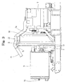
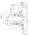
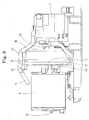
Additionally, the present invention is not limited to the first
embodiment of the present invention. For example, as the second
embodiment shown in Fig. 7 through Fig. 9, as well as the first
embodiment, the present invention also can be adapted to the
configuration in which the oil cooler 9 is large sized and the
turbocharger cooler 11 and the air conditioner capacitor 10 are
arranged up and down at the front side of the oil cooler 9.
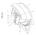
The configurations shown in the first and second embodiments
are the Back To Back (BTB) type in which the oil cooler 9 and the
radiator 8 are arranged to be superposed back and forth against
the flow of the cooling air, however, the present invention also
can be adapted to a configuration of the Side By Side (SBS) type
as shown in the third embodiment shown in Fig. 10 and the fourth
embodiment shown in Fig. 11 through Fig. 14 in which the oil cooler
9 and the radiator 8 are arranged adjacent to each other at the
left and right sides.
In the configuration shown in the third and fourth embodiments,
on the front side of the oil cooler 9 and the radiator 8 that are
arranged to be adjacent to each other at left and right sides, the
turbocharger cooler 11 is arranged at the upper part and the air
conditioner capacitor 10 is arranged at the lower part. However,
in the configuration of the third embodiment, the turbocharger
cooler 11 is swigably supported by the oil cooler 9 and the radiator
8 so as to swing up and down and is structured to change the posture
between the cooling posture and the open posture. On the other hand,
the air conditioner capacitor 10 is supported by the oil cooler
9 so as to swing horizontally and is structured to change the posture
between the cooling posture and the open posture.
In the configuration shown in the third embodiment, maintenance
such as cleaning, inspection, repair of the oil cooler 9 and the
radiator 8 arranged at the rear side can be performed by allowing
the air conditioner capacitor 10 and the turbocharger cooler 11
arranged at the front side to be held at an open posture.
Further, in the fourth embodiment, it is configured such that
only the air conditioner capacitor 10 changes the postures between
the cooling posture and the open posture.
Specifically, in the configuration shown in the fourth
embodiment, the turbocharger cooler 11 is bolted to the front face
of the case frame 23 in which the oil cooler 9 and the radiator
8 are assembled via the left and right fitting brackets 24. In this
case, between the turbocharger cooler 11, the oil cooler 9 and the
radiator 8, an appropriate space S through which a cleaning worker
can visually observe the core sections of the cooling devices 8,
9, and 11 from the lower direction of the turbocharger cooler 11
is secured. In Fig. 11 to Fig. 14, the reference numeral 25 denote
an air supply pipe connected to the turbocharger cooler 11, however,
because in the fourth embodiment, it is structured so that the
turbocharger cooler 11 does not change the postures, thus the air
supply pipe 25 is not required to deform, the configuration of the
fourth embodiment differs from the configurations in the first
through embodiments, thereby using the conventional general-purpose
air supply pipe 25.
On the other hand, in the configuration of the fourth embodiment,
the air conditioner capacitor 10 is supported by and fixed to a
square frame-like support member 26 and a pair of upper and lower
hinge 27 are attached to the left end section of the support member
26 at the one side. At the left side of the case frame 23 in which
the oil cooler 9 and the radiator 8 are assembled, a first support
bracket 28 protruding in the frontward direction is fixed. At the
first support bracket 28, the second support bracket 29 protruding
in the right direction is fixed. And the pair of hinges 27 are
attached to the second support bracket 29 at the other side so that
the support member 26 can be pivotably swung back and forth around
the pin shaft of the hinge 27. As a result, the air conditioner
capacitor 10 is structured to change the postures integrally with
the support member 26 between the cooling posture in which the air
conditioner capacitor 10 is arranged in parallel with the radiator
8 and the oil cooler 9 so as to be cooled by the cooling fan and
an open posture in which the air conditioner capacitor 10 is swung
from the cooling posture to the front side so that the front face
lower halves of the radiator 8 and the oil cooler 9 are opened.
The pipe 30 through which the cooling medium flows is connected
to the left end of the air conditioner capacitor 10, and the one
side of the pipe 30 to which the air conditioner capacitor 10 is
connected is composed of a steel pipe 30a. A flexible hose 30b is
connected to the tip end of the steel pipe 30a so as to respond
to the above-described posture change of the air conditioner
capacitor 10. The above steel pipe 30a is designed to slightly
project from the left end of the air conditioner capacitor 10 to
the left outside and to bend forward, thereby preventing the pipe
30 from interfering with other members such as the hinge 27 and
the second support bracket 29 when the air conditioner capacitor
10 has an open posture.
In Fig. 11 to Fig. 14, the reference numeral 31 denotes a latching
device with a handle 31a provided at the right side of the support
member 26, and the reference numeral 32 denotes a latch receiving
fixture provided at the third support bracket 33 fixed to the right
side part of the case frame 23 so as to be engageably locked by
the latching device 31, thereby allowing the air conditioner
capacitor 10 to be held at a cooling posture, and at the same time
allowing an operator to swing the air conditioner capacitor 10 with
a light control force.
In the configuration of the fourth embodiment as described above,
the oil cooler 9 and the radiator 8 are arranged adjacent to each
other left and right, at the front side of these oil cooler 9 and
radiator 8, the turbocharger cooler 11 is placed at the upper side
and the air conditioner capacitor 10 is placed at the lower side.
When the cooling device in this configuration is cleaned, the
air conditioner capacitor 10 is allowed to be held at an open posture,
thereby the rear face side of the air conditioner capacitor 10,
and the front face lower halves of the oil cooler 9 and of the radiator
8 are exposed, thus these parts can be easily cleaned. On the other
hand, as described above, between the turbocharger cooler 11, the
oil cooler 9, and the radiator 8, the appropriate space S through
which a cleaning worker can visually observe the core section of
the cooling devices from the lower part of the turbocharger cooler
11 is secured. As a result, the cleaning worker standing at ground
level can visually observe from the lower direction the core section
of the cooling device by allowing the air conditioner capacitor
10 arranged at the lower side of the turbocharger cooler 11 to be
held at an open posture, thereby allowing the cooling devices to
be cleaned easily without damaging the core section, thus improving
workability.
Additionally, in the configuration of the fourth embodiment,
only the air conditioner capacitor 10 among the cooling devices
provided at the front side of the oil cooler 9 and the radiator
8 is structured to change the postures between the cooling posture
and the open posture, and the turbocharger cooler 11 is bolted.
Thus, when repair of the oil cooler 9 and the radiator 8 is performed,
the turbocharger cooler 11 is required to be removed. But in case
of a construction machine, such as a hydraulic shovel which works
at construction site with lots of dust, cleaning of cooling devices
is required to be frequently performed, cleaning can be performed
without removing the turbocharger cooler 11 while observing the
core section.
Further in the fourth embodiment, the air conditioner capacitor
10 which is arranged at the lower side among the cooling devices
arranged adjacent to each other at the upper and lower sides is
structured so as to change the postures. Thus, by allowing the air
conditioner capacitor 10 to be held at an open posture, an operator
responsible for cleaning can visually observe appropriate space
S between the turbocharger cooler 11, the oil cooler 9 and the
radiator 8 from the lower direction, thereby a cleaning worker can
clean at ground level (or in a condition where a cleaning worker
stands on the crawler upper face in the case of a large construction
machine) avoiding trouble such as climbing on the upper face of
the upper rotating body 3 to clean the cooling device, thus
contributing to improvements in workability.
Further, the present invention can also be adapted to a
configuration in which only the air conditioner capacitor is
arranged at the front side or at the rear side of the radiator and/or
the oil cooler or a configuration in which the air conditioner
capacitor and the turbocharger cooler are arranged to be superposed
back and forth, for example.
In the second, third and fourth embodiments, components
identical to those in the first embodiment are provided with the
same reference numerals.
As described above, a cooling device in a construction machine
according to the present invention can be effectively used for
cooling devices including an oil cooler and a radiator that is
arranged by the Back To Back (BTB) or the Side By Side (SBS) method
in a construction machine such as a hydraulic shovel, more
specifically, the cooling device of the present invention is
particularly suitable for cooling devices in which the air
conditioner capacitor or the turbocharger cooler is arranged at
the front side of the radiator and/or the oil cooler.
Claims (9)
- A cooling device in a construction machine in which a plurality of cooling devices including an air conditioner capacitor are arranged to be superposed back and forth against the flow of the cooling air, wherein the air conditioner capacitor is structured to change the postures between a cooling posture in which the air conditioner capacitor is arranged in parallel with another cooling device and an open posture in which the front side or the rear side of the cooling device is exposed.
- The cooling device in a construction machine according to Claim 1 , in which the air conditioner capacitor and a turbocharger cooler are arranged at the front or rear sides of an oil cooler and/or a radiator against the flow of the cooling air, wherein the air conditioner capacitor and the turbocharger cooler are structured to change the postures between the cooling posture in which the air conditioner capacitor and the turbocharger cooler are provided in parallel with the oil cooler and/or the radiator, and an open posture in which the front side or the rear side of the oil cooler and/or the radiator is exposed.
- The cooling device in a construction machine according to Claim 1, in which the air conditioner capacitor and a turbocharger cooler are arranged at the front and rear sides of an oil cooler and/or a radiator against the flow of the cooling air, wherein the air conditioner capacitor is structured to change the postures between the cooling posture in which the air conditioner capacitor is arranged in parallel with the oil cooler and/or the radiator and an open posture in which the front side or the rear side of the oil cooler and/or the radiator is exposed.
- The cooling device in a construction machine according to Claim 2 or 3, wherein the oil cooler and the radiator are arranged adj acent to each other from side to side against the flow of the cooling air.
- The cooling device in a construction machine according to Claim 2 or 3, wherein the oil cooler and the radiator are arranged to be superposed back and forth against the flow of the cooling air.
- The cooling device in a construction machine according to Claim 5, wherein the oil cooler is structured to change the postures between the cooling posture in which the oil cooler is arranged in parallel with the radiator and an open posture in which the oil cooler is arranged such that the front side or the rear side of the radiator is exposed.
- The cooling device in a construction machine according to Claim 1, 2, 3, 4, 5, or 6, wherein the air conditioner capacitor and/or the turbocharger cooler is/are supported by the upper part of the radiator and/or the oil cooler so as to swing up and down.
- The cooling device in a construction machine according to Claim 1, 2, 3, 4, 5, or 6, wherein the air conditioner capacitor and/or the turbocharger cooler is/are supported by the left and right sides of the radiator or the oil cooler so as to swing back and forth.
- The cooling device in a construction machine according to Claim 1, 2, 3, 4, 5, 6, 7 or 8, wherein a pipe connected to the air conditioner capacitor and/or the turbocharger cooler can be deformed in accordance with the posture changes of the air conditioner capacitor and/or the turbocharger cooler.
Applications Claiming Priority (3)
| Application Number | Priority Date | Filing Date | Title |
|---|---|---|---|
| JP2002362435A JP2004001681A (en) | 2002-03-26 | 2002-12-13 | Cooling device in construction machine |
| JP2002362435 | 2002-12-13 | ||
| PCT/JP2003/011857 WO2004054828A1 (en) | 2002-12-13 | 2003-09-17 | Cooling device for construction machines |
Publications (2)
| Publication Number | Publication Date |
|---|---|
| EP1571017A1 true EP1571017A1 (en) | 2005-09-07 |
| EP1571017A4 EP1571017A4 (en) | 2006-05-17 |
Family
ID=32588157
Family Applications (1)
| Application Number | Title | Priority Date | Filing Date |
|---|---|---|---|
| EP03813290A Withdrawn EP1571017A4 (en) | 2002-12-13 | 2003-09-17 | Cooling device for construction machines |
Country Status (4)
| Country | Link |
|---|---|
| US (1) | US20050173095A1 (en) |
| EP (1) | EP1571017A4 (en) |
| CN (1) | CN1642764A (en) |
| WO (1) | WO2004054828A1 (en) |
Cited By (2)
| Publication number | Priority date | Publication date | Assignee | Title |
|---|---|---|---|---|
| EP3128078A1 (en) * | 2015-08-07 | 2017-02-08 | Ammann Schweiz AG | Paver and feeder |
| DE202018104562U1 (en) | 2018-08-08 | 2019-11-12 | Joseph Vögele AG | Paver or feeder vehicle with tank |
Families Citing this family (8)
| Publication number | Priority date | Publication date | Assignee | Title |
|---|---|---|---|---|
| DE102008040908A1 (en) * | 2008-07-31 | 2010-02-11 | Deere & Company, Moline | Radiator arrangement for a vehicle cooling system |
| US9435591B2 (en) * | 2012-09-10 | 2016-09-06 | Deere & Company | Heat exchanger pivotable for clean-out |
| JP5382669B1 (en) * | 2012-10-16 | 2014-01-08 | 株式会社小松製作所 | Excavator |
| JP6152605B2 (en) * | 2013-10-17 | 2017-06-28 | キャタピラー エス エー アール エル | Construction machinery |
| CN104126044B (en) | 2013-12-04 | 2015-09-30 | 株式会社小松制作所 | Hydraulic crawler excavator |
| CN106284474B (en) * | 2016-09-23 | 2018-05-22 | 广西玉柴重工有限公司 | A kind of mute explosion-proof air-conditioner system of hydraulic crawler excavator |
| JP7686352B2 (en) * | 2021-12-28 | 2025-06-02 | 株式会社クボタ | Support structure for heat exchanger for work vehicle and work vehicle |
| JP2025006869A (en) * | 2023-06-30 | 2025-01-17 | 株式会社クボタ | Work Machine |
Family Cites Families (9)
| Publication number | Priority date | Publication date | Assignee | Title |
|---|---|---|---|---|
| US3334704A (en) * | 1965-06-11 | 1967-08-08 | Int Harvester Co | Vehicle heat exchanger assembly |
| DE4122512A1 (en) * | 1991-05-28 | 1992-12-03 | Kloeckner Humboldt Deutz Ag | COMPACT HEAT EXCHANGER FAN UNIT |
| DE19547348C2 (en) * | 1995-12-19 | 1998-05-20 | Fortschritt Erntemaschinen | Self-propelled forage harvester |
| GB2336662B (en) * | 1998-04-21 | 2002-04-10 | Agco Gmbh & Co | Vehicle cooling radiator arrangement |
| JP2000280760A (en) * | 1999-04-01 | 2000-10-10 | Mitsubishi Agricult Mach Co Ltd | Working traveling car |
| GB2355700A (en) * | 1999-10-27 | 2001-05-02 | Caterpillar Inc | Slidable heat-exchanger core elements for a mobile machine |
| JP2001121941A (en) * | 1999-10-28 | 2001-05-08 | Denso Corp | Vehicle-mounted structure of heat exchanger |
| JP2001348909A (en) * | 2000-06-02 | 2001-12-21 | Shin Caterpillar Mitsubishi Ltd | Construction machinery |
| DE10206551B4 (en) * | 2002-02-16 | 2008-09-25 | CNH Österreich GmbH | Radiator arrangement for tractors |
-
2003
- 2003-09-17 WO PCT/JP2003/011857 patent/WO2004054828A1/en not_active Ceased
- 2003-09-17 EP EP03813290A patent/EP1571017A4/en not_active Withdrawn
- 2003-09-17 US US10/511,138 patent/US20050173095A1/en not_active Abandoned
- 2003-09-17 CN CNA03806605XA patent/CN1642764A/en active Pending
Cited By (2)
| Publication number | Priority date | Publication date | Assignee | Title |
|---|---|---|---|---|
| EP3128078A1 (en) * | 2015-08-07 | 2017-02-08 | Ammann Schweiz AG | Paver and feeder |
| DE202018104562U1 (en) | 2018-08-08 | 2019-11-12 | Joseph Vögele AG | Paver or feeder vehicle with tank |
Also Published As
| Publication number | Publication date |
|---|---|
| CN1642764A (en) | 2005-07-20 |
| EP1571017A4 (en) | 2006-05-17 |
| US20050173095A1 (en) | 2005-08-11 |
| WO2004054828A1 (en) | 2004-07-01 |
Similar Documents
| Publication | Publication Date | Title |
|---|---|---|
| EP1943121B1 (en) | Cooling device for construction machine | |
| JP5234693B2 (en) | Construction machinery | |
| US20050173095A1 (en) | Cooling device for construction machines | |
| WO2003002364A1 (en) | Cover structure for construction machine cooling package | |
| JPWO2009101935A1 (en) | Construction machinery | |
| JP2011529538A (en) | Cooling system mounting configuration for machines | |
| CN100408767C (en) | Construction mechanism | |
| US20170314230A1 (en) | Working machine | |
| JPH0527237U (en) | Engine cooling system for construction machinery | |
| JP5387665B2 (en) | Work machine | |
| JP5455482B2 (en) | Opening and closing structure of cooling device | |
| JP4183584B2 (en) | Construction machine cooling system | |
| JP2008025416A (en) | Construction machine | |
| JP2001288777A (en) | Construction machine | |
| JP4213479B2 (en) | Construction machinery | |
| JP4792452B2 (en) | Heat exchange equipment for construction machinery | |
| US8827018B2 (en) | Work vehicle | |
| JP6886380B2 (en) | Work vehicle | |
| JP2011140839A (en) | Construction machine | |
| JP6973114B2 (en) | Cooling equipment for construction machinery | |
| JP2004001681A (en) | Cooling device in construction machine | |
| JP4896865B2 (en) | Construction equipment fuel cooling system | |
| JP3450754B2 (en) | Structure for improving cleanability of cooler and method for improving cleanability of cooler | |
| JP2003020679A (en) | Work vehicle with upper turning function | |
| JP3884935B2 (en) | Construction machine cooling package |
Legal Events
| Date | Code | Title | Description |
|---|---|---|---|
| PUAI | Public reference made under article 153(3) epc to a published international application that has entered the european phase |
Free format text: ORIGINAL CODE: 0009012 |
|
| 17P | Request for examination filed |
Effective date: 20050613 |
|
| AK | Designated contracting states |
Kind code of ref document: A1 Designated state(s): AT BE BG CH CY CZ DE DK EE ES FI FR GB GR HU IE IT LI LU MC NL PT RO SE SI SK TR |
|
| RBV | Designated contracting states (corrected) |
Designated state(s): DE FR |
|
| A4 | Supplementary search report drawn up and despatched |
Effective date: 20060405 |
|
| 17Q | First examination report despatched |
Effective date: 20061010 |
|
| STAA | Information on the status of an ep patent application or granted ep patent |
Free format text: STATUS: THE APPLICATION HAS BEEN WITHDRAWN |
|
| 18W | Application withdrawn |
Effective date: 20070115 |