EP1570985A2 - Device for controlling the pressing force of an adjustable mounted roll - Google Patents
Device for controlling the pressing force of an adjustable mounted roll Download PDFInfo
- Publication number
- EP1570985A2 EP1570985A2 EP05103000A EP05103000A EP1570985A2 EP 1570985 A2 EP1570985 A2 EP 1570985A2 EP 05103000 A EP05103000 A EP 05103000A EP 05103000 A EP05103000 A EP 05103000A EP 1570985 A2 EP1570985 A2 EP 1570985A2
- Authority
- EP
- European Patent Office
- Prior art keywords
- roller
- pressure
- rollers
- adjustable
- adjusting
- Prior art date
- Legal status (The legal status is an assumption and is not a legal conclusion. Google has not performed a legal analysis and makes no representation as to the accuracy of the status listed.)
- Withdrawn
Links
- 238000007639 printing Methods 0.000 claims abstract description 16
- 238000000034 method Methods 0.000 claims abstract description 7
- 230000001105 regulatory effect Effects 0.000 abstract description 2
- 239000012528 membrane Substances 0.000 description 3
- 230000001276 controlling effect Effects 0.000 description 2
- 238000005096 rolling process Methods 0.000 description 2
- 230000000694 effects Effects 0.000 description 1
- 230000005489 elastic deformation Effects 0.000 description 1
- 239000013013 elastic material Substances 0.000 description 1
- 238000007646 gravure printing Methods 0.000 description 1
- XLYOFNOQVPJJNP-UHFFFAOYSA-N water Substances O XLYOFNOQVPJJNP-UHFFFAOYSA-N 0.000 description 1
Images


Classifications
-
- B—PERFORMING OPERATIONS; TRANSPORTING
- B41—PRINTING; LINING MACHINES; TYPEWRITERS; STAMPS
- B41F—PRINTING MACHINES OR PRESSES
- B41F31/00—Inking arrangements or devices
- B41F31/30—Arrangements for tripping, lifting, adjusting, or removing inking rollers; Supports, bearings, or forks therefor
- B41F31/32—Lifting or adjusting devices
- B41F31/36—Lifting or adjusting devices fluid-pressure operated
-
- B—PERFORMING OPERATIONS; TRANSPORTING
- B41—PRINTING; LINING MACHINES; TYPEWRITERS; STAMPS
- B41F—PRINTING MACHINES OR PRESSES
- B41F13/00—Common details of rotary presses or machines
- B41F13/08—Cylinders
- B41F13/24—Cylinder-tripping devices; Cylinder-impression adjustments
- B41F13/34—Cylinder lifting or adjusting devices
- B41F13/40—Cylinder lifting or adjusting devices fluid-pressure operated
-
- B—PERFORMING OPERATIONS; TRANSPORTING
- B41—PRINTING; LINING MACHINES; TYPEWRITERS; STAMPS
- B41F—PRINTING MACHINES OR PRESSES
- B41F31/00—Inking arrangements or devices
- B41F31/30—Arrangements for tripping, lifting, adjusting, or removing inking rollers; Supports, bearings, or forks therefor
- B41F31/301—Devices for tripping and adjusting form rollers
-
- B—PERFORMING OPERATIONS; TRANSPORTING
- B41—PRINTING; LINING MACHINES; TYPEWRITERS; STAMPS
- B41F—PRINTING MACHINES OR PRESSES
- B41F7/00—Rotary lithographic machines
- B41F7/20—Details
- B41F7/24—Damping devices
- B41F7/40—Devices for tripping or lifting damping rollers; Supporting, adjusting, or removing arrangements therefor
Definitions
- the invention relates to a device for adjusting the contact pressure of an adjustable mounted roller according to the preamble of claim 1.
- rollers In conventional printing machines, such as web-fed rotary printing presses, there are a variety of rollers available.
- ink rollers are provided, the serve the transfer of color from a color memory on the plate cylinder.
- the inking rollers can be dosed the color transferred to the plate cylinders, so that the color is transmitted as a uniform film of a certain thickness. Faults, like for example, speed variations and torsional vibrations can thereby be compensated.
- dampening rollers can be provided in the printing press, the a dampening solution, such as water, transferred to the printing unit.
- pairs of rollers are formed by mutually engaging rollers at where at least one of the rollers has a cylindrical surface of elastic material, so that this cylindrical surface depends on the contact pressure of the opposite roller at least slightly deformed.
- the result is given by the elastic Deformation of the roll surface extending straight between the rolls Contact area, referred to as a contact strip.
- the width of the contact strip can be varied by creating the contact pressure between the rollers, the width of the contract strip has a significant influence on the print result Has. For example, if the contact strip is too narrow in an inking unit, it will not enough color transfer, whereas in cases where the contact strip too wide is, the elastic roller can be damaged by the occurring flexing work.
- DE 38 08 142 A1 describes a device for supporting two cylinders. Here is the contact pressure between two on and off rolls by changing the Pressure of the print medium changeable. Also, a switching device is arranged with which the pressure medium can be guided optionally to different actuators.
- the setting of the Contact pressure and / or the employment of the first roller to the second roller at simultaneous rotation of the rolls is a preferred embodiment.
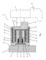
- Fig. 1 is a device 20 for adjusting the contact pressure between a first Roller 21 and a second roller 22 are shown.
- the roller 21 can with the ends of their Axis 23 or pin releasably provided on a device 20 on the Quick release fastened 24.
- Such quick fasteners are out of the art known in the art and have a semicircular bearing shell, in which the ends the axis 23 can be inserted. By attaching a in Fig. 1 not shown upper bearing shell can then the axis 23 on the quick release 24th be determined.
- the device 20 is essentially composed of a frame holder 26 and a Roll holder 27 constructed, the relative to each other in a plane that is perpendicular extends to the drawing plane, can be moved against each other.
- the Frame holder 26 is made of a base plate 28, for example by means of a Swivel arm can be pivotally attached to the frame of a printing press, and a sleeve body 29 constructed.
- On the side facing the roller 21 has the Sleeve body 29 a recess 31 into which a cylindrical portion 32 of the Roller holder 27 engages.
- the inner diameter of the recess 31 and the outer diameter of the section 32 is chosen so that a in the Basic position circular cylindrical gap 33 with a gap width of about 1 mm to 10 mm, in particular of about 2 mm. Through the gap 33, the maximum adjustment range for Adjustment of the roller holder 27 relative to the frame holder 26 defined.
- actuating movements can or the desired contact pressure between the roller 21 and to apply the roller 22 are distributed in the gap 33 over the circumference total four actuators 34 in the form of pressure hoses 34, of which in FIG. 1 only two are shown in section, arranged.
- Feed lines 48 can be formed by the walls of the actuators 34
- Pressure chambers 36 are pressurized.
- the roller 21 is pressed against the roller 22 with the desired contact pressure can be. Because the air cushion pressurized in the actuators 34 is compressible is, mechanical disturbances can be caused by the resulting spring action be intercepted.
- Lammellen implant 37 attached to the attached to the sleeve body 29 Lammellen implantn 38 arranged to form a Lammellenps combing are.
- Lammellen implantn 37 and 38th formed Lammellenps 37 and 38 is a cross-sectionally T-shaped punch 39th provided, the circular punch head 40 with an annular flange 41 at the outermost Lammellenelement 37 and 38 of the Lammellenpers to the plant comes.
- a pressure plate 42 is attached, on which the spring force of a trained in the manner of a plate spring package 43
- Spring element 43 acts.
- the spring element 43 is biased between the pressure plate 42 and the sleeve body 29 mounted so that of the Lammellenmaschinen 37 and 38 formed Lammellenb by the spring force from the punch 39 on the Lammellenmaschine 37 and 38 is transmitted, is clamped.
- the adjustment of the contact pressure between the rollers 21 and 22 takes place, for example in the following way.
- the pressure chamber 46 with a sufficient pressure acted upon, so that the Lammellenimplantation 37 and 38 no longer frictionally be pinched.
- the actuators 34 each with just as much pressure urges that the desired contact pressure between the rollers 21 and 22 or between the roller 21 and others, not shown in Fig. 1 Rolling forms and leads to a contact strip of the desired width.
- the pressure chamber 46 is depressurized, whereby the punch 39 the Lammellenmaschine 37 and 38 clamped together, so that the roller holder 27 relative is fixed to the frame holder 26 in the desired position.
- Last will be the actors 34 depressurises.
- the roll holder 27 and, as a result, the attached thereto roller 21 are laterally offset relative to the frame holder 26, which by a corresponding control of the actuators 34 and the consequent Force effect on the section 32 is effected.
- the desired position of Roller holder 27 is found relative to the frame holder 26, which can be from the Lammellenimplantationn 37 and 38 or the punch 39 and the pressure plate 42 formed fixing device are actuated, so that the position is permanently fixed and the actuators 34 need not be driven further.
- FIG. 4 the device 20 with base plate 28 in a perspective view of shown in front.
- the sleeve body 29 is by means of four fastening screws 47 on the Base plate 28 attached (see Fig. 1, shown schematically).
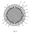
- FIG. 5 shows a second exemplary embodiment of an actuator 50 for a device 20 in FIG Cross-section.
- the basic structure of the device 20 with frame holder 26, Roller holder 27 and a fixing device for fixing the roller holder 27 relative to the roll holder 26 corresponds to the structure described with Fig. 1 and therefore must will not be explained further.
- To form the actuator 50 is in the gap 33 a cylindrical membrane 51, whose upper and lower edges with the inner diameter the sleeve body 29 is connected (not shown in Fig. 5) arranged.
- the Membrane 51 is also in four strip-shaped areas 52 with the Inner diameter of the sleeve body 29 connected, for example glued, so As a result, through the sleeve body 29 and the diaphragm 51 four pressure chambers 53rd are formed, which are distributed uniformly over the circumference of the gap 33.
- the Pressure chambers 53 can each have pressure inlet openings 54 with compressed air be acted upon, so depending on the pressure in the four pressure chambers 53, a resultant force acts on the portion 32 of the roll holder 27.
- the rollers 21a; 21c; 21e are employed on the roller 22a.
- the rollers 21a; 21c; 21e can by pressurizing the various actuators 34 on the rollers 21 a to 21e, the contact pressure between the various rollers 57; 21a to 21e; 22a be set.
- roller 22a On the roller 22a is one or more fasteners 58 or Interruptions 58 are provided, which are designed in particular in the manner of a gap 58 is.
- the front and rear edge of a Pressure plate are fixed to attach the pressure plate to the roller 22a.
- the Rotation angle of the roller 22a is detected by a sensor, not shown, and to the Control forwarded.
- adjusting the rollers 21a; 21c; 21e or at the Adjustment of the contact pressure of these rollers 21a; 21c; 21e will be the respective Angle of rotation of the roller 22a taken into account, thereby preventing the rollers 21a; 21c; 21e when hiring or when adjusting the contact pressure at the Interrupt 58 are present.
- the setting of the rollers 21a to 21e or their Adjustment to the roller 22a can also be used with a rotating printing unit with a rotating roller 22a done.
- the adjustment of the contact pressure and / or the employment of the first Rolls 21a to 21e to the second roller 22a takes place at low speeds, especially at 3,000 to 5,000 U / h ..
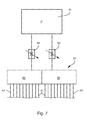
- the switching device 59 shown in Fig. 7 is suitable for driving the a total of 20 actuators on the adjustable rollers 21a to 21e on one side.
- the Switching device 59 is shown only schematically and is below briefly explained.
- a pressure medium such as compressed air with be taken sufficiently high pressure level.
- the pressure medium flows into two separate Pressure chambers 64; 66, in which, depending on the position of the pressure control valves 62 and 63 there is a corresponding pressure level.
- Pressure lines 67 Associated with each actuator 34 Pressure lines 67, the set in the pressure chambers 64 and 66, the pressure to the Actuators 34 are transmitted.
- the changeover of the changeover device 59 is clocked.
- the duration of a time clock for Adjustment of an adjustable roller 21a to 21e of the inking unit 56 or dampening unit is 0.1 to 2 seconds, especially 0.5 seconds.
- Adjusting the contact pressure means that the contact pressure in the salaried state (in contact) of the roller to another roller before hiring or hired Condition is changeable, d. H. the surface pressure of the roller is in addition to parked condition changeable.
Landscapes
- Engineering & Computer Science (AREA)
- Mechanical Engineering (AREA)
- Inking, Control Or Cleaning Of Printing Machines (AREA)
- Spinning Or Twisting Of Yarns (AREA)
- Treatments Of Macromolecular Shaped Articles (AREA)
- Delivering By Means Of Belts And Rollers (AREA)
- Fixing For Electrophotography (AREA)
- Treatment Of Fiber Materials (AREA)
- Rolls And Other Rotary Bodies (AREA)
Abstract
Description
Die Erfindung betrifft eine Vorrichtung zum Einstellen des Anpressdrucks einer verstellbar gelagerten Walze gemäß dem Oberbegriff des Anspruches 1.The invention relates to a device for adjusting the contact pressure of an adjustable mounted roller according to the preamble of claim 1.
In herkömmlichen Druckmaschinen, wie beispielsweise Rollenrotationsdruckmaschinen, sind eine Vielzahl von Walzen vorhanden. Insbesondere sind Farbwalzen vorgesehen, die der Übertragung der Farbe aus einem Farbspeicher auf die Plattenzylinder dienen. Durch die Farbwalzen kann die auf die Plattenzylinder übertragene Farbe dosiert werden, sodass die Farbe als einheitlicher Film bestimmter Dicke übertragen wird. Störungen, wie zum Beispiel Geschwindigkeitsschwankungen und Drehschwingungen können dadurch ausgeglichen werden.In conventional printing machines, such as web-fed rotary printing presses, There are a variety of rollers available. In particular, ink rollers are provided, the serve the transfer of color from a color memory on the plate cylinder. By the inking rollers can be dosed the color transferred to the plate cylinders, so that the color is transmitted as a uniform film of a certain thickness. Faults, like for example, speed variations and torsional vibrations can thereby be compensated.
Außerdem können in der Druckmaschine auch Feuchtwerkwalzen vorgesehen sein, die ein Feuchtmittel, beispielsweise Wasser, auf das Druckwerk übertragen.In addition, dampening rollers can be provided in the printing press, the a dampening solution, such as water, transferred to the printing unit.
Häufig werden Walzenpaare von miteinander in Eingriff stehenden Walzen gebildet, bei denen zumindest eine der Walzen eine Zylinderfläche aus elastischem Material aufweist, sodass diese Zylinderfläche abhängig vom Anpressdruck der gegenüberliegenden Walze zumindest geringfügig verformt werden kann. Im Ergebnis ergibt sich durch die elastische Verformung der Walzenoberfläche ein sich gradlinig zwischen den Walzen erstreckender Kontaktbereich, der als Kontaktstreifen bezeichnet wird. Die Breite des Kontaktstreifens kann durch die Erstellung des Anpressdrucks zwischen den Walzen variiert werden, wobei die Breite des Kontraktstreifens einen erheblichen Einfluss auf das Druckergebnis hat. Ist beispielsweise in einem Farbwerk der Kontaktstreifen zu schmal, so wird nicht genug Farbe übertragen, wohingegen in den Fällen, in denen der Kontaktstreifen zu breit ist, die elastische Walze durch die dabei auftretende Walkarbeit beschädigt werden kann. Frequently, pairs of rollers are formed by mutually engaging rollers at where at least one of the rollers has a cylindrical surface of elastic material, so that this cylindrical surface depends on the contact pressure of the opposite roller at least slightly deformed. The result is given by the elastic Deformation of the roll surface extending straight between the rolls Contact area, referred to as a contact strip. The width of the contact strip can be varied by creating the contact pressure between the rollers, the width of the contract strip has a significant influence on the print result Has. For example, if the contact strip is too narrow in an inking unit, it will not enough color transfer, whereas in cases where the contact strip too wide is, the elastic roller can be damaged by the occurring flexing work.
Um insbesondere die Streifenbreite jeweils abhängig von den Betriebsbedingungen, beispielsweise der Temperatur der Druckmaschinen beziehungsweise deren Verschleißgrad, immer richtig einstellen zu können, ist es erforderlich, die eine Walze verstellbar zu lagern, sodass sie mit einem Aktor mit einer einstellbaren Kraft in Richtung der gegenüberliegenden Walze gedrückt werden kann. Ist dann der richtige Anpressdruck zwischen den beiden Walzen gefunden, wird eine Fixiereinrichtung zum Fixieren der ersten Walze relativ zur zweiten Walze betätigt, um den Anpressdruck dauerhaft aufrecht zu erhalten.In particular, the strip width depending on the operating conditions, for example, the temperature of the printing machines or their Wear level, to always be able to adjust correctly, it is necessary to use the one roller to be stored in an adjustable position so that they are provided with an actuator with an adjustable force in the direction the opposite roller can be pressed. Is then the right contact pressure found between the two rollers, a fixing device for fixing the pressed first roller relative to the second roller to sustain the contact pressure permanently to obtain.
Aus der DE 197 19 305 A1 ist eine Vorrichtung zum Einstellen des Anpressdruckes zwischen zwei Walzen bekannt. Bei der dort beschriebenen Lageranordnung wird die verstellbar gelagerte Walze mit einer Feder, die sich am Gestell der Druckmaschine abstützt, gegen die gegenüberliegende Walze gedrückt. Dadurch stellt sich abhängig von der jeweils gewählten Federkennlinie immer ein bestimmter Anpressdruck zwischen den beiden Walzen aus. Zur Fixierung der Walze in der angepressten Stellung ist ein Klemmmechanismus mit Klemmhebel und Klemmplatte beschrieben, durch den die Walzenachse durch Reibschluss am Gestell der Druckmaschine fixierbar ist.From DE 197 19 305 A1 is a device for adjusting the contact pressure known between two rollers. In the bearing assembly described there is the Adjustable mounted roller with a spring, located on the frame of the printing press supported, pressed against the opposite roller. As a result, depends on the selected spring characteristic always a certain contact pressure between the two rolls off. To fix the roller in the pressed position is a Clamping mechanism with clamping lever and clamping plate described by the Roll axis can be fixed by friction on the frame of the printing press.
Aus der DE 199 19 733 A1 ist eine Vorrichtung zum halbautomatischen Einstellen von Walzen bekannt, bei der die verstellbar gelagerte Walze in einem Walzenhalter gehalten wird, der seinerseits an einem gestellfest angeordneten Rahmenhalter gelagert ist. Walzenhalter und Rahmenhalter können dabei gegeneinander verschoben werden und sind durch federelastische Mittel miteinander verbunden. Die federelastischen Mittel weisen dabei eine bestimmte Vorspannung auf, sodass die am Walzenhalter verstellbar gelagerte Walze mit einem bestimmten Anpressdruck gegen die gegenüberliegende Walze gedrückt werden kann. Zur Arretierung des Walzenhalters am Rahmenhalter sind Arretierbolzen vorgesehen, durch deren Zustellung der Walzenhalter reibschlüssig am Rahmenhalter beklemmt werden kann. From DE 199 19 733 A1 a device for semi-automatic adjustment of Rollers known in which the adjustably mounted roller held in a roll holder is, which in turn is mounted on a frame-mounted frame holder. Roller holder and frame holder can be moved against each other and are interconnected by elastic means. The elastic means have a certain bias, so that adjustable on the roll holder mounted roller with a certain contact pressure against the opposite Roller can be pressed. To lock the roller holder on the frame holder are Locking bolt provided by the delivery of the roll holder frictionally on Frame holder can be jammed.
Die DE 38 08 142 A1 beschreibt eine Vorrichtung zum Lagern zweier Zylinder. Hierbei ist der Anpressdruck zwischen zwei an- und abstellbarer Walzen mittels Veränderung des Druckes des Druckmediums veränderbar. Auch ist ein Umschalteinrichtung angeordnet, mit der das Druckmedium wahlweise an verschiedene Aktoren führbar ist.DE 38 08 142 A1 describes a device for supporting two cylinders. Here is the contact pressure between two on and off rolls by changing the Pressure of the print medium changeable. Also, a switching device is arranged with which the pressure medium can be guided optionally to different actuators.
Die DE-OS 16 11 303 offenbart eine Vorrichtung zum An- und Abstellen eines Druckzylinders einer Tiefdruckmaschine, wobei ein Druckminderventil vorgesehen ist.DE-OS 16 11 303 discloses a device for turning on and off a Printing cylinder of a gravure printing machine, wherein a pressure reducing valve is provided.
Durch die US 2 774 301 A und die GB 12 13 935 A sind Farbwalzen bekannt, die mittels druckmittelbetätigbarer Aktoren anstellbar sind. Hierbei ist ein Ventil zum Einstellen der Höhe des Druckes und zumindest ein Absperrventil vorgesehen.By the US 2,774,301 A and GB 12 13 935 A ink rollers are known by means of pressure-actuable actuators are adjustable. Here is a valve for adjusting the Height of the pressure and at least one shut-off valve provided.
Der Erfindung liegt die Aufgabe zugrunde, eine Vorrichtung zum Einstellen des Anpressdrucks einer verstellbar gelagerten Walze zu schaffen.The invention has for its object to provide a device for adjusting the To create contact pressure of an adjustably mounted roller.
Die Aufgabe wird erfindungsgemäß durch die Merkmale des Anspruches 1 gelöst.The object is achieved by the features of claim 1.
Bei der Vorrichtung ist der Aktor zur Einstellung des Anpressdrucks in der Art eines mit einem Druckmedium, ein vorgespanntes Gas, insbesondere Druckluft, beaufschlagbaren Druckkörper ausgebildet. Zur Einstellung des Drucks des Druckmediums, um den Anpressdruck verändern zu können, sind Ventile vorgesehen. Da an einem Feucht- oder Farbwerk eine Vielzahl von einstellbaren Walzen vorgesehen sind, wäre eine der Anzahl der Aktoren entsprechende Anzahl von Ventilen normalerweise notwendig, was einen hohen gerätetechnischen Aufwand bedeutete. Dieser hohe Aufwand wird dadurch vermieden, dass eine Umschalteinrichtung vorgesehen ist, mit der die Stellventile wahlweise an verschiedene Aktoren anschließbar sind. Dies bedeutet mit anderen Worten, dass die einstellbaren Walzen dann nicht mehr alle gleichzeitig eingestellt werden können, sondern jeweils nur die Aktoren betätigbar sind, die über die Umschalteinrichtung mit den Einstellventilen verbunden sind. Je nach Ausbildung des Farb- oder Feuchtwerkes reichen aber zur Einstellung des gesamten Farb- oder Feuchtwerks wenige Ventile, mit denen nacheinander der Anpressdruck der verschiedenen einstellbaren Walzen eingestellt wird.In the apparatus, the actuator for adjusting the contact pressure in the manner of a a pressurized medium, a biased gas, in particular compressed air acted upon Pressure body formed. To adjust the pressure of the print media to the To be able to change the contact pressure, valves are provided. Because of a wet or Inking a variety of adjustable rollers are provided, would be one of the number the actuators corresponding number of valves normally necessary, giving a meant high equipment expense. This high effort is thereby avoided that a switching device is provided with the control valves optionally connectable to different actuators. This means with others Words that the adjustable rollers are then not all set at the same time can, but only the actuators are actuated, via the switching device connected to the adjusting valves. Depending on the design of the color or However, dampening units are only enough to set the entire inking or dampening system Valves with which successively the contact pressure of the various adjustable Rolling is adjusted.
Nach einer bevorzugten Ausführungsform sind lediglich zwei Ventile vorgesehen, mit denen dann gleichzeitig der Druck von zwei Aktoren an einer einstellbaren Walze einstellbar ist. Zur Einstellung der verschiedenen einstellbaren Walzen wird dann so vorgegangen, dass jeweils eine einstellbare Walze durch Betätigung der beiden Ventile justiert wird und nach der Justierung durch Betätigung der Fixiereinrichtung die Einstellung fixiert wird. Nach der Fixierung kann dann mit der Einstellung der nächsten einstellbaren Walze fortgefahren werden.According to a preferred embodiment, only two valves are provided with which then simultaneously the pressure of two actuators on an adjustable roller is adjustable. To adjust the various adjustable rollers then so Proceeded that in each case an adjustable roller by actuation of the two valves is adjusted and after the adjustment by pressing the fixing the Setting is fixed. After fixation can then with the setting of the next adjustable roller to be continued.
Nach dem Verfahren wird die Winkellage der zweiten Walze, an der die erste Walze mit einstellbaren Anpressdruck angedrückt wird, erfasst. Durch Kontrolle dieser Winkellage ist es möglich, dass das Anpressen bzw. Anstellen der einstellbaren Walze dann nur in bestimmten Winkellagen der zweiten Walze durchgeführt wird.After the process, the angular position of the second roller on which the first roller with adjustable contact pressure is pressed, recorded. By controlling this angular position is it is possible that the pressing or adjusting the adjustable roller then only in certain angular positions of the second roller is performed.
Diese Art der Kontrolle des Andrückens ist besonders bei Formzylindern von Bedeutung, an deren Umfang Befestigungsmittel zur Befestigung der Druckplatten vorgesehen sind. Wird nämlich die Einstellung bzw. Anstellung der einstellbaren Walzen gerade in einer Winkellage vorgenommen, bei der die einstellbare Walze auf der Befestigungseinrichtung des Formzylinders zur Anlage kommt, werden die eingestellten Werte durch den veränderten Durchmesser im Bereich der Befestigungseinrichtung verfälscht. Diese Verfälschung kann durch die Kontrolle der Winkellage der zweiten Walze ausgeschlossen werden.This type of control of the pressure is particularly important in the form of cylinders, at the periphery of fastening means for fixing the printing plates are provided. Namely, the setting or employment of adjustable rollers in a straight Angular position made at which the adjustable roller on the fastening device of the forme cylinder comes to rest, the set values by the changed diameter in the field of fastening device falsified. These Falsification can be excluded by controlling the angular position of the second roller become.
Nach einer weiteren bevorzugten Ausführungsform folgt die Einstellung des Anpressdrucks und/oder die Anstellung der ersten Walze an die zweite Walze bei gleichzeitiger Rotation der Walzen.According to another preferred embodiment, the setting of the Contact pressure and / or the employment of the first roller to the second roller at simultaneous rotation of the rolls.
Ausführungsbeispiele der Erfindung sind in den Zeichnungen dargestellt und werden im folgenden näher beschrieben.Embodiments of the invention are illustrated in the drawings and are in described in more detail below.
Es zeigen:
- Fig. 1
- eine schematisch dargestellte Vorrichtung zum Einstellen des Anpressdrucks zwischen zwei Walzen im Längsschnitt;
- Fig. 2
- die schematisch im Querschnitt dargestellte Vorrichtung gemäß Fig. 1 in einer Grundstellung;
- Fig. 3
- die schematisch im Querschnitt dargestellte Vorrichtung gemäß Fig. 1 in einer ausgelenkten Stellung;
- Fig. 4
- die Vorrichtung gemäß Fig. 1 in einer perspektivischen Ansicht von vorne;
- Fig. 5
- ein zweites Ausführungsbeispiel eines Aktors für eine Vorrichtung im Querschnitt;
- Fig. 6
- ein Farbwerk mit mehreren einstellbaren Walzen zur Anstellung an einem Formzylinder;
- Fig. 7
- eine Umschalteinrichtung zur wahlweisen Umschaltung zweier Ventile zwischen verschiedenen Aktoren.
- Fig. 1
- a schematically illustrated device for adjusting the contact pressure between two rollers in longitudinal section;
- Fig. 2
- the device shown schematically in cross-section according to Figure 1 in a basic position.
- Fig. 3
- the device shown schematically in cross-section of Figure 1 in a deflected position.
- Fig. 4
- the device of Figure 1 in a perspective view from the front.
- Fig. 5
- a second embodiment of an actuator for a device in cross section;
- Fig. 6
- an inking unit with several adjustable rollers for employment on a forme cylinder;
- Fig. 7
- a switching device for selectively switching two valves between different actuators.
In Fig. 1 ist eine Vorrichtung 20 zum Einstellen des Anpressdruckes zwischen einer ersten
Walze 21 und einer zweiten Walze 22 dargestellt. Die Walze 21 kann mit den Enden ihrer
Achse 23 bzw. Zapfen lösbar an einem an der Vorrichtung 20 vorgesehenen
Schnellverschluss 24 befestigt werden. Derartige Schnellverschlüsse sind aus dem Stand
der Technik bekannt und weisen eine halbkreisförmige Lagerschale auf, in die die Enden
der Achse 23 eingelegt werden können. Durch Befestigung einer in Fig. 1 nicht
dargestellten oberen Lagerschale kann dann die Achse 23 am Schnellverschluss 24
festgelegt werden.In Fig. 1 is a
Die Vorrichtung 20 ist im wesentlichen aus einem Rahmenhalter 26 und einem
Walzenhalter 27 aufgebaut, die relativ zueinander in einer Stellebene, die sich senkrecht
zur Zeichenebene erstreckt, gegeneinander verschoben werden können. Der
Rahmenhalter 26 ist aus einer Grundplatte 28, die beispielsweise mittels eines
Schwenkarms schwenkbar an dem Gestell einer Druckmaschine befestigt werden kann,
und einem Hülsenkörper 29 aufgebaut. Auf der zur Walze 21 weisenden Seite weist der
Hülsenkörper 29 eine Ausnehmung 31 auf, in die ein zylinderförmiger Abschnitt 32 des
Walzenhalters 27 eingreift. Der Innendurchmesser der Ausnehmung 31 beziehungsweise
der Außendurchmesser des Abschnitts 32 ist dabei so gewählt, dass sich ein in der
Grundstellung kreiszylindrischer Spalt 33 mit einer Spaltbreite von ca. 1 mm bis 10 mm,
insbesondere von ca. 2 mm bildet. Durch den Spalt 33 wird der maximale Stellbereich zur
Verstellung des Walzenhalters 27 relativ zum Rahmenhalter 26 definiert.The
Um die bei der Einstellung der Walze 21 erforderlichen Stellbewegungen realisieren zu
können beziehungsweise den gewünschten Anpressdruck zwischen der Walze 21 und
der Walze 22 aufbringen zu können, sind im Spalt 33 über den Umfang verteilt insgesamt
vier in der Art von Druckschläuchen 34 ausgebildete Aktoren 34, von denen in Fig. 1
lediglich zwei im Schnitt dargestellt sind, angeordnet. Über in Fig. 1 nicht dargestellte
Zuleitungen 48 (siehe Fig. 4) können die von der Wandung der Aktoren 34 gebildete
Druckkammern 36 mit Druck beaufschlagt werden. Abhängig von den jeweiligen
Druckverhältnissen in den vier Aktoren 34 wirkt auf den Walzenhalter 27 eine
resultierende Kraft, sodass durch entsprechende Ansteuerung des Drucks in den Aktoren
34 die Walze 21 mit dem gewünschten Anpressdruck gegen die Walze 22 gedrückt
werden kann. Da das in den Aktoren 34 unter Druck stehende Luftpolster kompressibel
ist, können mechanische Störungen durch die daraus resultierende Federwirkung
abgefangen werden.To realize the required in the setting of the
Zur Fixierung des Walzenhalters 27 relativ zum Rahmenhalter 26 sind am Walzenhalter
27 Lammellenelemente 37 befestigt die mit am Hülsenkörper 29 befestigten
Lammellenelementen 38 unter Bildung eines Lammellenpakets kämmend angeordnet
sind. Zur reibschlüssigen Beklemmung des aus den Lammellenelementen 37 und 38
gebildeten Lammellenpakets 37 bzw. 38 ist ein im Querschnitt T-förmiger Stempel 39
vorgesehen, dessen kreisförmiger Stempelkopf 40 mit einem kreisringförmigen Flansch
41 am äußersten Lammellenelement 37 bzw. 38 des Lammellenpakets zur Anlage
kommt. Am gegenüberliegenden Ende des Stempels 39 ist eine Druckplatte 42 befestigt,
auf die die Federkraft eines in der Art eines Tellerfederpakets 43 ausgebildeten
Federelements 43 wirkt. Das Federelement 43 wird vorgespannt zwischen die Druckplatte
42 und den Hülsenkörper 29 montiert, sodass das von den Lammellenelementen 37 und
38 gebildete Lammellenpaket durch die Federkraft, die vom Stempel 39 auf die
Lammellenelemente 37 und 38 übertragen wird, beklemmt wird.For fixing the
Zur Verstellung des Walzenhalters 27 relativ zum Rahmenhalter 26, insbesondere beim
Einstellen des Anpressdruckes zwischen den Walzen 21 und 22 muss die von den
Lammellenelementen 37 und 38 beziehungsweise dem Stempel 39 und der Druckplatte
42 gebildete Fixiereinrichtung gelöst werden. Dazu ist in der Grundplatte 28 ein
Druckanschluss 44 vorgesehen, durch den eine Druckkammer 46 zwischen der
Druckplatte 42 und der Grundplatte 28 mit einem Druckmedium, beispielsweise Druckluft
beaufschlagt werden kann. Sobald der auf die Druckplatte 42 wirkende Luftdruck die
Federkraft des Federelements 43 übersteigt, wird der Stempel 39 soweit vom äußersten
Lammellenelement 37 bzw. 38 abgehoben, dass diese nicht mehr reibschlüssig beklemmt
sind und relativ gegeneinander verschoben werden können. For adjusting the
Die Einstellung des Anpressdrucks zwischen den Walzen 21 und 22 erfolgt beispielsweise
in folgender Weise. Zunächst wird die Druckkammer 46 mit einem ausreichenden Druck
beaufschlagt, sodass die Lammellenelemente 37 und 38 nicht mehr reibschlüssig
beklemmt werden. Anschließend werden die Aktoren 34 jeweils mit gerade soviel Druck
beaufschlagt, dass sich der gewünschte Anpressdruck zwischen den Walzen 21 und 22
beziehungsweise zwischen der Walze 21 und weiteren, in Fig. 1 nicht dargestellten
Walzen ausbildet und zu einem Kontaktstreifen der gewünschten Breite führt. Sobald die
richtige Einstellung mit dem gewünschten Anpressdruck zwischen den Walzen 21 und 22
gefunden ist, wird die Druckkammer 46 druckentleert, wodurch der Stempel 39 die
Lammellenelemente 37 und 38 miteinander beklemmt, sodass der Walzenhalter 27 relativ
zum Rahmenhalter 26 in der gewünschten Stellung fixiert ist. Zuletzt werden die Aktoren
34 druckentleert.The adjustment of the contact pressure between the
In Fig. 2 und 3 ist das Wirkprinzip der Vorrichtung 20 bei der erforderlichen Stellbewegung
in schematischer Weise dargestellt. Fig. 2 zeigt den Rahmenhalter 26 mit der
Ausnehmung 31 und den darin eingreifenden Abschnitt 32 des Walzenhalters 27. Durch
die Wahl der Abmessungen wird zwischen dem Rahmenhalter 26 und dem Abschnitt 32
des Walzenhalters 27 ein Spalt 33 gebildet, in dem die in Fig. 2 und 3 lediglich
schematisch durch Kraftpfeile angedeuteten Aktoren 34 angeordnet sind. Die möglichen
Stellbewegungen zwischen dem Rahmenhalter 26 und dem Walzenhalter 27 werden
durch eine Stellebene, die sich in der Darstellung von Fig. 2 und 3 in der Zeichenebene
erstreckt, definiert, wobei der Stellbereich der Stellbewegungen durch die Breite des
Spalts 33 begrenzt ist.In Fig. 2 and 3, the operating principle of the
Wie in Fig. 3 beispielhaft dargestellt, kann der Walzenhalter 27 und damit im Ergebnis die
daran befestigte Walze 21 relativ zum Rahmenhalter 26 seitlich versetzt werden, was
durch eine entsprechende Ansteuerung der Aktoren 34 und der daraus folgenden
Kraftwirkung auf den Abschnitt 32 bewirkt wird. Sobald die gewünschte Stellung des
Walzenhalters 27 relativ zum Rahmenhalter 26 gefunden ist, kann die von den
Lammellenelementen 37 und 38 beziehungsweise dem Stempel 39 und der Druckplatte
42 gebildete Fixiereinrichtung betätigt werden, sodass die Stellung dauerhaft fixiert ist und
die Aktoren 34 nicht weiter angetrieben werden müssen.As shown by way of example in FIG. 3, the
In Fig. 4 ist die Vorrichtung 20 mit Grundplatte 28 in einer perspektivischen Ansicht von
vorne dargestellt. Der Hülsenkörper 29 wird mittels vier Befestigungsschrauben 47 an der
Grundplatte 28 befestigt (siehe Fig. 1, schematisch dargestellt). Zwischen dem
Hülsenkörper 29 des Rahmenhalters 26 und dem Walzenhalter 27, auf dessen nach
vorne gerichteten Seite der halbschalenförmige Schnellverschluss 24 teilweise erkennbar
ist (siehe Fig. 1), sind die vier in der Art von Druckschläuchen 34 ausgebildeten Aktoren
34 angeordnet, die über Zuleitungen 48 mit Druckluft beaufschlag werden können. Mittels
der Druckplatte 42 können die erkennbaren Lammellenelemente 37 und 38 entspannt
werden.In Fig. 4, the
Man erkennt die außerordentlich kompakte Bauweise der Vorrichtung 20, die aufgrund
ihrer insgesamt rotationssymmetrischen Ausbildung (abgesehen von der Grundplatte 28)
einen kleineren Durchmesser aufweist, als die Walze 21 selbst (siehe Fig.1).One recognizes the extremely compact design of the
Fig. 5 zeigt ein zweites Ausführungsbeispiel eines Aktors 50 für eine Vorrichtung 20 im
Querschnitt. Der grundsätzliche Aufbau der Vorrichtung 20 mit Rahmenhalter 26,
Walzenhalter 27 und einer Fixiereinrichtung zur Fixierung des Walzenhalters 27 relativ
zum Walzenhalter 26 entspricht dem mit Fig. 1 beschriebenen Aufbau und muss deshalb
nicht weiter erläutert werden. Zur Bildung des Aktors 50 wird im Spalt 33 eine
zylinderförmige Membran 51, deren oberer und unterer Rand mit dem Innendurchmesser
des Hülsenkörpers 29 verbunden ist (in Fig. 5 nicht dargestellt), angeordnet. Die
Membran 51 wird in zudem in vier streifenförmigen Bereichen 52 mit dem
Innendurchmesser des Hülsenkörpers 29 verbunden, beispielsweise festgeklebt, sodass
im Ergebnis durch den Hülsenkörper 29 und die Membran 51 vier Druckkammern 53
gebildet werden, die gleichmäßig über den Umfang des Spalts 33 verteilt sind. Die
Druckkammern 53 können jeweils über Druckeinlassöffnungen 54 mit Druckluft
beaufschlagt werden, sodass abhängig vom jeweiligen Druck in den vier Druckkammern
53 eine resultierende Kraft auf den Abschnitt 32 des Walzenhalters 27 wirkt.FIG. 5 shows a second exemplary embodiment of an
In Fig. 6 ist ein Farbwerk 56 dargestellt, mit dem von einer Walze 57 Druckfarbe auf eine
in der Art eines Formzylinders 22a ausgebildete Walze 22a übertragen werden kann. Zur
Übertragung der Druckfarbe sind im Farbwerk 56 fünf einstellbare Walzen 21a; 21b; 21c;
21d; 21e vorgesehen. Die Enden der einstellbaren Walzen 21a bis 21e sind jeweils in
Vorrichtungen 20 gelagert, was in Fig. 6 durch die entsprechenden Aktoren 34 angedeutet
ist.In Fig. 6, an inking
Auch können an den Formzylinder 22a vier oder fünf Walzen 21a; 21b; 21c; 21d; 21e,
beispielsweise eine Feuchtauftragswalze und drei oder vier Farbauftragwalzen aufgestellt
werden.Also, four or five
Durch Druckbeaufschlagung der entsprechenden Aktoren 34 können die Walzen 21a;
21c; 21e an die Walze 22a angestellt werden. Nach Anstellung der Walzen 21a; 21c; 21e
kann durch Druckbeaufschlagung der verschiedenen Aktoren 34 an den Walzen 21 a bis
21e der Anpressdruck zwischen den verschiedenen Walzen 57; 21a bis 21e; 22a
eingestellt werden.By pressurizing the
An der Walze 22a ist eine bzw. mehrere Befestigungseinrichtungen 58 oder
Unterbrechungen 58 vorgesehen, die insbesondere in der Art eines Spalts 58 ausgebildet
ist. In der Befestigungseinrichtung 58 können die Vorder- bzw. Hinterkante einer
Druckplatte festgelegt werden, um die Druckplatte an der Walze 22a zu befestigen. Der
Drehwinkel der Walze 22a wird durch einen nicht dargestellten Sensor erfasst und an die
Steuerung weitergeleitet. Beim Anstellen der Walzen 21a; 21c; 21e bzw. bei der
Einstellung des Anpressdruckes dieser Walzen 21a; 21c; 21e wird der jeweilige
Drehwinkel der Walze 22a berücksichtigt, um dadurch zu verhindern, dass die Walzen
21a; 21c; 21e bei der Anstellung bzw. bei der Einstellung des Anpressdruckes an der
Unterbrechung 58 anliegen. Die Einstellung der Walzen 21a bis 21e bzw. deren
Anstellung an die Walze 22a kann auch bei rotierendem Druckwerk mit rotierender Walze
22a erfolgen. Die Einstellung des Anpressdrucks und/oder die Anstellung der ersten
Walzen 21a bis 21e an die zweite Walze 22a erfolgt bei geringen Drehzahlen,
insbesondere bei 3.000 bis 5.000 U/Std..On the
Die in Fig. 7 dargestellte Umschalteinrichtung 59 ist geeignet zur Ansteuerung der
insgesamt 20 Aktoren an den einstellbaren Walzen 21a bis 21e auf einer Seite. Die
Umschalteinrichtung 59 ist dabei lediglich schematisch dargestellt und wird nachfolgend
kurz erläutert.The switching
Aus einem Druckspeicher 61 kann ein Druckmedium, beispielsweise Druckluft mit
ausreichend hohem Druckniveau entnommen werden. Über zwei Ventile 62; 63,
insbesondere Druckregelventile 62; 63 strömt das Druckmedium in zwei getrennte
Druckkammern 64; 66, in denen abhängig von der Stellung der Druckregelventile 62 und
63 ein entsprechendes Druckniveau herrscht. Über jedem Aktor 34 zugeordnete
Druckleitungen 67 kann der in den Druckkammern 64 bzw. 66 eingestellte Druck zu den
Aktoren 34 übertragen werden.From a
Die Umstellung der Umstelleinrichtung 59 erfolgt getaktet. Die Dauer eines Zeittaktes zur
Einstellung einer einstellbaren Walze 21a bis 21e des Farbwerks 56 oder Feuchtwerks
beträgt 0,1 bis 2 Sekunden, insbesondere 0,5 Sekunden.The changeover of the
In der Umschalteinrichtung 59 sind nun in Fig. 7 nicht dargestellte Absperreinrichtungen,
beispielsweise Absperrventile vorgesehen, so dass wahlweise verschiedene der an die
Druckkammern 64 und 66 angeschlossenen Druckleitungen 67 abgesperrt werden
können. Soll nun der Anpressdruck an einer einstellbaren Walze 21 eingestellt werden, so
werden alle Druckleitungen 67 abgesperrt, die zu Aktoren 34 führen, die für die
Einstellung nicht erforderlich sind. Im Ergebnis folgt daraus, dass der durch die
Druckregelventile 62; 63 eingeregelte Luftdruck nur zu den Aktoren 34 übertragen
werden, die an der Einstellung der jeweils gewünschten Walze 21 beteiligt sind. Nach der
Einstellung dieser Walze 21 wird der entsprechende Anpressdruck durch Betätigung der
Fixiereinrichtung fixiert, so dass durch Umschaltung der Umschalteinrichtung 59
anschließend die nächste einstellbare Walze 21 eingestellt werden kann.In the
Anstelle der Umschalteinrichtung 59 mit Absperreinrichtung ist folgende Alternative
möglich.Instead of the
Die von beiden Druckregelventile 62; 63 eingestellten Luftdrücke liegen gleichzeitig an
den Aktoren 34; 50 von mehreren Einstellvorrichtungen an. Nur bei den
Einstellvorrichtungen bei denen die Fixiereinrichtung geöffnet wird erfolgt eine Einstellung.The of both
Die anzustellende Walze 21; 21a; 21b; 21c; 21d; 21e die Mantelfläche der zweiten Walze
22; 22a bezogen auf die Umfangsrichtung in einen Abstand von kleiner 20 mm von dem
vorlaufenden Ende der Unterbrechung 58 erfolgt.The
Einstellen des Anpressdrucks bedeutet, dass der Anpressdruck im angestellten Zustand (in Kontakt) der Walze an eine andere Walze vor dem Anstellen oder im angestellten Zustand veränderbar ist, d. h. die Flächenpressung der Walze ist zusätzlich zum abgestellten Zustand veränderbar. Adjusting the contact pressure means that the contact pressure in the salaried state (in contact) of the roller to another roller before hiring or hired Condition is changeable, d. H. the surface pressure of the roller is in addition to parked condition changeable.
- 01 bis 1901 to 19
- --
- 2020
- Vorrichtungcontraption
- 2121
- Walzeroller
- 2222
- Walzeroller
- 2323
- Achseaxis
- 2424
- Schnellverschlussquick release
- 2525
- --
- 2626
- Rahmenhalterframe holder
- 2727
- Walzenhalterroller holder
- 2828
- Grundplatte (26)Base plate (26)
- 2929
- Hülsenkörper (26)Sleeve body (26)
- 3030
- --
- 3131
- Ausnehmung (26)Recess (26)
- 3232
- Abschnitt (27)Section (27)
- 3333
- Spaltgap
- 3434
- Aktor, DruckschlauchActuator, pressure hose
- 3535
- --
- 3636
- Druckkammerpressure chamber
- 3737
- Lammellenelement (27)Lammella element (27)
- 3838
- Lammellenelement (26)Lamellar element (26)
- 3939
- Stempelstamp
- 4040
- Stempelkopfram head
- 4141
- Flansch (40)Flange (40)
- 4242
- Druckplatteprinting plate
- 4343
- Federelement, TellerfederpaketSpring element, plate spring package
- 4444
- Druckanschlusspressure connection
- 4545
- - -
- 4646
- Druckkammerpressure chamber
- 4747
- Befestigungsschraubefixing screw
- 4848
- Zuleitungsupply
- 4949
- --
- 5050
- Aktoractuator
- 5151
- Membranmembrane
- 5252
- Befestigungsabschnittattachment section
- 5353
- Druckkammerpressure chamber
- 5454
- DruckeinlassöffnungPressure inlet port
- 5555
- --
- 5656
- Farbwerkinking
- 5757
- Walzeroller
- 5858
- Befestigungseinrichtung, Unterbrechung, SpaltFastening device, interruption, gap
- 5959
- Umschalteinrichtungswitchover
- 6060
- --
- 6161
- Druckspeicheraccumulator
- 6262
- Ventil, DruckregelventilValve, pressure control valve
- 6363
- Ventil, DruckregelventilValve, pressure control valve
- 6464
- Druckkammerpressure chamber
- 6565
- --
- 6666
- Druckkammerpressure chamber
- 6767
- Druckleitungpressure line
- 21a21a
- Walzeroller
- 21b21b
- Walzeroller
- 21c21c
- Walzeroller
- 21d21d
- Walzeroller
- 21e21e
- Walzeroller
- 22a22a
- Walze, FormzylinderRoller, forme cylinder
Claims (7)
Applications Claiming Priority (3)
| Application Number | Priority Date | Filing Date | Title |
|---|---|---|---|
| DE2002144046 DE10244046B4 (en) | 2002-09-21 | 2002-09-21 | Device for adjusting the contact pressure of an adjustably mounted roller |
| DE10244046 | 2002-09-21 | ||
| EP03798064A EP1539495B1 (en) | 2002-09-21 | 2003-09-05 | Devices and methods for setting the contact pressure of a displaceably mounted roller |
Related Parent Applications (1)
| Application Number | Title | Priority Date | Filing Date |
|---|---|---|---|
| EP03798064A Division EP1539495B1 (en) | 2002-09-21 | 2003-09-05 | Devices and methods for setting the contact pressure of a displaceably mounted roller |
Publications (2)
| Publication Number | Publication Date |
|---|---|
| EP1570985A2 true EP1570985A2 (en) | 2005-09-07 |
| EP1570985A3 EP1570985A3 (en) | 2006-07-12 |
Family
ID=31983981
Family Applications (5)
| Application Number | Title | Priority Date | Filing Date |
|---|---|---|---|
| EP03798064A Expired - Lifetime EP1539495B1 (en) | 2002-09-21 | 2003-09-05 | Devices and methods for setting the contact pressure of a displaceably mounted roller |
| EP05103008A Withdrawn EP1570987A3 (en) | 2002-09-21 | 2003-09-05 | Method for adjusting the pressing force of an adjustable mounted roll |
| EP05103004A Expired - Lifetime EP1570986B1 (en) | 2002-09-21 | 2003-09-05 | Method for controlling the pressing force of an adjustable mounted roll |
| EP05103011A Withdrawn EP1570988A3 (en) | 2002-09-21 | 2003-09-05 | Method for controlling the pressing force of an adjustable mounted roll |
| EP05103000A Withdrawn EP1570985A3 (en) | 2002-09-21 | 2003-09-05 | Device for controlling the pressing force of an adjustable mounted roll |
Family Applications Before (4)
| Application Number | Title | Priority Date | Filing Date |
|---|---|---|---|
| EP03798064A Expired - Lifetime EP1539495B1 (en) | 2002-09-21 | 2003-09-05 | Devices and methods for setting the contact pressure of a displaceably mounted roller |
| EP05103008A Withdrawn EP1570987A3 (en) | 2002-09-21 | 2003-09-05 | Method for adjusting the pressing force of an adjustable mounted roll |
| EP05103004A Expired - Lifetime EP1570986B1 (en) | 2002-09-21 | 2003-09-05 | Method for controlling the pressing force of an adjustable mounted roll |
| EP05103011A Withdrawn EP1570988A3 (en) | 2002-09-21 | 2003-09-05 | Method for controlling the pressing force of an adjustable mounted roll |
Country Status (8)
| Country | Link |
|---|---|
| US (3) | US7387069B2 (en) |
| EP (5) | EP1539495B1 (en) |
| JP (1) | JP4307382B2 (en) |
| CN (2) | CN1331669C (en) |
| AT (2) | ATE461042T1 (en) |
| AU (1) | AU2003266200A1 (en) |
| DE (5) | DE10261983A1 (en) |
| WO (1) | WO2004028810A1 (en) |
Families Citing this family (18)
| Publication number | Priority date | Publication date | Assignee | Title |
|---|---|---|---|---|
| DE10261983A1 (en) * | 2002-09-21 | 2004-04-08 | Koenig & Bauer Ag | Method for adjusting the contact pressure of an adjustable roller |
| DE102004004665B4 (en) | 2004-01-30 | 2005-12-29 | Koenig & Bauer Ag | Device for adjusting a pressing force exerted by a roller in a roller strip on an adjacent rotary body and for setting the roller against the rotary body or for stopping the roller from the rotary body |
| EP1955846A1 (en) * | 2005-04-21 | 2008-08-13 | Koenig & Bauer Aktiengesellschaft | Joint control of setting for printing cylinders and applicator rolls |
| DE102006028434B4 (en) * | 2005-06-23 | 2014-01-30 | Koenig & Bauer Aktiengesellschaft | Printing unit of a printing press with at least two printing units |
| JP2007229954A (en) * | 2006-02-27 | 2007-09-13 | Mitsubishi Heavy Ind Ltd | Nip recognizing system of printing machine and program of the same |
| DE102006030290B3 (en) * | 2006-03-03 | 2007-10-18 | Koenig & Bauer Aktiengesellschaft | printing unit |
| WO2007099148A2 (en) | 2006-03-03 | 2007-09-07 | Koenig & Bauer Aktiengesellschaft | Printing groups of a printing press |
| US8919250B2 (en) * | 2010-08-02 | 2014-12-30 | Goss International Americas, Inc. | Printing press and method for positioning cylinders therein |
| US8854634B2 (en) * | 2012-06-14 | 2014-10-07 | Xerox Corporation | Transfix roller with adjustable crown for use in an indirect printer |
| US8888480B2 (en) | 2012-09-05 | 2014-11-18 | Aprecia Pharmaceuticals Company | Three-dimensional printing system and equipment assembly |
| CN104640686B (en) | 2012-09-05 | 2018-01-30 | 阿普雷奇亚制药公司 | 3D printing system and device components |
| AU2014228990B2 (en) | 2013-03-15 | 2017-02-02 | Aprecia Pharmaceuticals LLC | Rapid disperse dosage form containing levetiracetam |
| FR3004671B1 (en) * | 2013-04-22 | 2015-05-22 | Pakea | MACHINE FOR THE CONTINUOUS MANUFACTURE OF TUBULAR BODIES OF BOXES, IN PARTICULAR CARDBOARD OR SIMILAR |
| CN104908409A (en) * | 2015-06-01 | 2015-09-16 | 铜陵方正塑业科技有限公司 | Printing device |
| CN116423825A (en) | 2015-08-21 | 2023-07-14 | 阿普雷奇亚制药有限责任公司 | Three-dimensional printing system and equipment assembly |
| US10765658B2 (en) | 2016-06-22 | 2020-09-08 | Mastix LLC | Oral compositions delivering therapeutically effective amounts of cannabinoids |
| CN112297605A (en) * | 2020-10-10 | 2021-02-02 | 山东华冠智能卡有限公司 | RFID antenna lithography apparatus based on graphite alkene conductive paste |
| CN112895683A (en) * | 2020-12-28 | 2021-06-04 | 安徽庆丰余防伪科技有限公司 | A compression fittings for antifalsification label |
Citations (6)
| Publication number | Priority date | Publication date | Assignee | Title |
|---|---|---|---|---|
| US2774301A (en) | 1953-05-13 | 1956-12-18 | Hoe & Co R | Ink roller mounting for printing machines |
| GB1213935A (en) | 1968-02-07 | 1970-11-25 | Albert Schnellpressen | Improvements in or relating to inking apparatus for rotary printing presses |
| DE1611303A1 (en) | 1968-01-29 | 1970-12-10 | Albert Schnellpressen | Device for turning the printing cylinder on and off with the intermediate roller opposite the forme cylinder on rotogravure printing machines |
| DE3808142A1 (en) | 1988-03-11 | 1989-09-21 | Goebel Gmbh Maschf | STORAGE FACILITIES |
| DE19719305A1 (en) | 1997-05-07 | 1998-11-12 | Roland Man Druckmasch | Printing press roller mounting |
| DE19919733A1 (en) | 1998-05-22 | 1999-11-25 | Heidelberger Druckmasch Ag | Device and method for the semi-automatic adjustment of rollers |
Family Cites Families (20)
| Publication number | Priority date | Publication date | Assignee | Title |
|---|---|---|---|---|
| DE64064C (en) | l. D. craig in San Francisco, Staat Californien, V. St. A | Strips provided with adhesive on both sides for connecting sheets of paper and the like | ||
| US2306044A (en) * | 1939-05-05 | 1942-12-22 | Davidson William Ward | Printing press |
| US3157118A (en) * | 1962-07-02 | 1964-11-17 | Miller Printing Machinery Co | Printing press |
| US3389450A (en) * | 1966-05-20 | 1968-06-25 | Mount Hope Machine Company Inc | Non-deflecting roll |
| DE1561014B1 (en) * | 1967-03-02 | 1970-02-12 | Maschf Augsburg Nuernberg Ag | Adjustable roller bearings, in particular for distribution and application rollers of inking units on printing machines |
| DE3820026A1 (en) * | 1988-06-13 | 1989-12-14 | Heidelberger Druckmasch Ag | DEVICE FOR THE POWERFUL CLUTCHING OF A FIXED GEAR WHEEL AND AN ADJUSTING GEAR WHEEL ON A CYLINDER OF A TURNING DEVICE IN AN ARC ROTATION PRINTING MACHINE AND ELECTRICAL PROTECTION OF SUCH A DEVICE |
| DE4216781C2 (en) * | 1992-05-21 | 1995-08-03 | Heidelberger Druckmasch Ag | Device for receiving rotary body pins |
| DE4231673C2 (en) | 1992-09-22 | 1994-11-10 | Roland Man Druckmasch | Device for roller adjustment in printing machines |
| US5448949A (en) * | 1993-08-24 | 1995-09-12 | Heidelberger Druckmaschinen Ag | Method and device for adjusting a contact pressure between ink-carrying cylinders of a printing machine |
| DE4436629C2 (en) | 1994-10-13 | 1998-08-13 | Koenig & Bauer Albert Ag | Bearing bush |
| CN2210784Y (en) * | 1995-01-17 | 1995-10-25 | 邵一康 | Supplying, transfering, uniforming and ink-applicating mechanism of label printing machine |
| US5678485A (en) * | 1995-12-22 | 1997-10-21 | Heidelberger Druckmaschinen Ag | Counterpoise and lift mechanism |
| DE19717305A1 (en) | 1997-04-24 | 1998-11-05 | Hans Hager | Crank drive for heavy loads |
| DE19822662C2 (en) * | 1998-05-20 | 2003-12-24 | Roland Man Druckmasch | Process for color reproduction on an image data oriented printing machine |
| US6098542A (en) | 1999-02-17 | 2000-08-08 | Heidelberger Druckmaschinen Ag | Method and device for force loading a rubber blanket roller in a printing press |
| DE10152020C2 (en) * | 2001-03-20 | 2003-05-08 | Koenig & Bauer Ag | Device for adjusting the contact pressure of an adjustable roller |
| DE10113314C2 (en) | 2001-03-20 | 2003-10-30 | Koenig & Bauer Ag | fixing |
| CN2493402Y (en) * | 2001-06-07 | 2002-05-29 | 万谙机械企业股份有限公司 | Printing unit of a printing press |
| ATE342801T1 (en) | 2001-12-06 | 2006-11-15 | Koenig & Bauer Ag | METHOD FOR OPERATING AN INKING UNIT OR DAMPENING UNIT IN A PRINTING PRESS |
| DE10261983A1 (en) * | 2002-09-21 | 2004-04-08 | Koenig & Bauer Ag | Method for adjusting the contact pressure of an adjustable roller |
-
2002
- 2002-09-21 DE DE10261983A patent/DE10261983A1/en not_active Withdrawn
- 2002-09-21 DE DE10261985A patent/DE10261985A1/en not_active Withdrawn
- 2002-09-21 DE DE10261984A patent/DE10261984A1/en not_active Withdrawn
-
2003
- 2003-09-05 EP EP03798064A patent/EP1539495B1/en not_active Expired - Lifetime
- 2003-09-05 EP EP05103008A patent/EP1570987A3/en not_active Withdrawn
- 2003-09-05 AU AU2003266200A patent/AU2003266200A1/en not_active Abandoned
- 2003-09-05 DE DE50313271T patent/DE50313271D1/en not_active Expired - Lifetime
- 2003-09-05 DE DE50312535T patent/DE50312535D1/en not_active Expired - Lifetime
- 2003-09-05 EP EP05103004A patent/EP1570986B1/en not_active Expired - Lifetime
- 2003-09-05 JP JP2004538700A patent/JP4307382B2/en not_active Expired - Fee Related
- 2003-09-05 AT AT03798064T patent/ATE461042T1/en not_active IP Right Cessation
- 2003-09-05 CN CNB038238152A patent/CN1331669C/en not_active Expired - Fee Related
- 2003-09-05 AT AT05103004T patent/ATE488365T1/en active
- 2003-09-05 WO PCT/DE2003/002946 patent/WO2004028810A1/en not_active Ceased
- 2003-09-05 CN CN2007100917947A patent/CN101041286B/en not_active Expired - Fee Related
- 2003-09-05 EP EP05103011A patent/EP1570988A3/en not_active Withdrawn
- 2003-09-05 EP EP05103000A patent/EP1570985A3/en not_active Withdrawn
- 2003-09-05 US US10/528,468 patent/US7387069B2/en not_active Expired - Fee Related
-
2008
- 2008-05-28 US US12/153,938 patent/US20080229961A1/en not_active Abandoned
- 2008-05-28 US US12/153,937 patent/US7765930B2/en not_active Expired - Fee Related
Patent Citations (6)
| Publication number | Priority date | Publication date | Assignee | Title |
|---|---|---|---|---|
| US2774301A (en) | 1953-05-13 | 1956-12-18 | Hoe & Co R | Ink roller mounting for printing machines |
| DE1611303A1 (en) | 1968-01-29 | 1970-12-10 | Albert Schnellpressen | Device for turning the printing cylinder on and off with the intermediate roller opposite the forme cylinder on rotogravure printing machines |
| GB1213935A (en) | 1968-02-07 | 1970-11-25 | Albert Schnellpressen | Improvements in or relating to inking apparatus for rotary printing presses |
| DE3808142A1 (en) | 1988-03-11 | 1989-09-21 | Goebel Gmbh Maschf | STORAGE FACILITIES |
| DE19719305A1 (en) | 1997-05-07 | 1998-11-12 | Roland Man Druckmasch | Printing press roller mounting |
| DE19919733A1 (en) | 1998-05-22 | 1999-11-25 | Heidelberger Druckmasch Ag | Device and method for the semi-automatic adjustment of rollers |
Also Published As
| Publication number | Publication date |
|---|---|
| WO2004028810A1 (en) | 2004-04-08 |
| AU2003266200A1 (en) | 2004-04-19 |
| DE10261983A1 (en) | 2004-04-08 |
| CN1688443A (en) | 2005-10-26 |
| EP1570987A3 (en) | 2006-07-12 |
| DE50312535D1 (en) | 2010-04-29 |
| US7765930B2 (en) | 2010-08-03 |
| US20060042485A1 (en) | 2006-03-02 |
| EP1570986A2 (en) | 2005-09-07 |
| JP4307382B2 (en) | 2009-08-05 |
| US20080229960A1 (en) | 2008-09-25 |
| DE50313271D1 (en) | 2010-12-30 |
| CN101041286B (en) | 2011-12-14 |
| DE10261984A1 (en) | 2004-04-08 |
| EP1570987A2 (en) | 2005-09-07 |
| EP1570988A2 (en) | 2005-09-07 |
| EP1570985A3 (en) | 2006-07-12 |
| ATE461042T1 (en) | 2010-04-15 |
| JP2005538876A (en) | 2005-12-22 |
| CN101041286A (en) | 2007-09-26 |
| DE10261985A1 (en) | 2004-04-08 |
| EP1539495B1 (en) | 2010-03-17 |
| EP1570988A3 (en) | 2006-07-12 |
| EP1570986A3 (en) | 2006-07-12 |
| CN1331669C (en) | 2007-08-15 |
| EP1539495A1 (en) | 2005-06-15 |
| US7387069B2 (en) | 2008-06-17 |
| ATE488365T1 (en) | 2010-12-15 |
| EP1570986B1 (en) | 2010-11-17 |
| US20080229961A1 (en) | 2008-09-25 |
Similar Documents
| Publication | Publication Date | Title |
|---|---|---|
| EP1539495B1 (en) | Devices and methods for setting the contact pressure of a displaceably mounted roller | |
| EP1461207B1 (en) | Method for operating an inking system or a dampening system in a printing machine | |
| EP1437221B1 (en) | Device for adjusting the contact pressure of an adjustably mounted cylinder | |
| DE10113314C2 (en) | fixing | |
| DE10244046B4 (en) | Device for adjusting the contact pressure of an adjustably mounted roller | |
| EP1528981A1 (en) | Cylinders of a web-fed printing press and printing unit | |
| DE10262042B4 (en) | For the adjustment of printing/wetting rollers, at an offset printing press, actuators are operated to move the rollers and set the pressures between them independently |
Legal Events
| Date | Code | Title | Description |
|---|---|---|---|
| PUAI | Public reference made under article 153(3) epc to a published international application that has entered the european phase |
Free format text: ORIGINAL CODE: 0009012 |
|
| AC | Divisional application: reference to earlier application |
Ref document number: 1539495 Country of ref document: EP Kind code of ref document: P |
|
| AK | Designated contracting states |
Kind code of ref document: A2 Designated state(s): AT BE BG CH CY CZ DE DK EE ES FI FR GB GR HU IE IT LI LU MC NL PT RO SE SI SK TR |
|
| AX | Request for extension of the european patent |
Extension state: LT LV MK |
|
| RIN1 | Information on inventor provided before grant (corrected) |
Inventor name: JENTZSCH, PETER Inventor name: FAIST, BERND Inventor name: SCHNEIDER, GEORG |
|
| PUAL | Search report despatched |
Free format text: ORIGINAL CODE: 0009013 |
|
| AK | Designated contracting states |
Kind code of ref document: A3 Designated state(s): AT BE BG CH CY CZ DE DK EE ES FI FR GB GR HU IE IT LI LU MC NL PT RO SE SI SK TR |
|
| AX | Request for extension of the european patent |
Extension state: LT LV MK |
|
| 17P | Request for examination filed |
Effective date: 20060621 |
|
| AKX | Designation fees paid |
Designated state(s): AT BE BG CH CY CZ DE DK EE ES FI FR GB GR HU IE IT LI LU MC NL PT RO SE SI SK TR |
|
| STAA | Information on the status of an ep patent application or granted ep patent |
Free format text: STATUS: THE APPLICATION HAS BEEN WITHDRAWN |
|
| 17Q | First examination report despatched |
Effective date: 20100507 |
|
| 18W | Application withdrawn |
Effective date: 20100520 |