EP1570975A2 - Apparatus for heat welding or heat embossing of plastic parts - Google Patents
Apparatus for heat welding or heat embossing of plastic parts Download PDFInfo
- Publication number
- EP1570975A2 EP1570975A2 EP05003982A EP05003982A EP1570975A2 EP 1570975 A2 EP1570975 A2 EP 1570975A2 EP 05003982 A EP05003982 A EP 05003982A EP 05003982 A EP05003982 A EP 05003982A EP 1570975 A2 EP1570975 A2 EP 1570975A2
- Authority
- EP
- European Patent Office
- Prior art keywords
- heating
- tool
- cooling
- cavity
- medium
- Prior art date
- Legal status (The legal status is an assumption and is not a legal conclusion. Google has not performed a legal analysis and makes no representation as to the accuracy of the status listed.)
- Withdrawn
Links
Images


Classifications
-
- B—PERFORMING OPERATIONS; TRANSPORTING
- B29—WORKING OF PLASTICS; WORKING OF SUBSTANCES IN A PLASTIC STATE IN GENERAL
- B29C—SHAPING OR JOINING OF PLASTICS; SHAPING OF MATERIAL IN A PLASTIC STATE, NOT OTHERWISE PROVIDED FOR; AFTER-TREATMENT OF THE SHAPED PRODUCTS, e.g. REPAIRING
- B29C65/00—Joining or sealing of preformed parts, e.g. welding of plastics materials; Apparatus therefor
- B29C65/02—Joining or sealing of preformed parts, e.g. welding of plastics materials; Apparatus therefor by heating, with or without pressure
- B29C65/18—Joining or sealing of preformed parts, e.g. welding of plastics materials; Apparatus therefor by heating, with or without pressure using heated tools
-
- B—PERFORMING OPERATIONS; TRANSPORTING
- B29—WORKING OF PLASTICS; WORKING OF SUBSTANCES IN A PLASTIC STATE IN GENERAL
- B29C—SHAPING OR JOINING OF PLASTICS; SHAPING OF MATERIAL IN A PLASTIC STATE, NOT OTHERWISE PROVIDED FOR; AFTER-TREATMENT OF THE SHAPED PRODUCTS, e.g. REPAIRING
- B29C59/00—Surface shaping of articles, e.g. embossing; Apparatus therefor
- B29C59/02—Surface shaping of articles, e.g. embossing; Apparatus therefor by mechanical means, e.g. pressing
-
- B—PERFORMING OPERATIONS; TRANSPORTING
- B29—WORKING OF PLASTICS; WORKING OF SUBSTANCES IN A PLASTIC STATE IN GENERAL
- B29C—SHAPING OR JOINING OF PLASTICS; SHAPING OF MATERIAL IN A PLASTIC STATE, NOT OTHERWISE PROVIDED FOR; AFTER-TREATMENT OF THE SHAPED PRODUCTS, e.g. REPAIRING
- B29C65/00—Joining or sealing of preformed parts, e.g. welding of plastics materials; Apparatus therefor
- B29C65/02—Joining or sealing of preformed parts, e.g. welding of plastics materials; Apparatus therefor by heating, with or without pressure
- B29C65/18—Joining or sealing of preformed parts, e.g. welding of plastics materials; Apparatus therefor by heating, with or without pressure using heated tools
- B29C65/24—Joining or sealing of preformed parts, e.g. welding of plastics materials; Apparatus therefor by heating, with or without pressure using heated tools characterised by the means for heating the tool
- B29C65/26—Hot fluid
-
- B—PERFORMING OPERATIONS; TRANSPORTING
- B29—WORKING OF PLASTICS; WORKING OF SUBSTANCES IN A PLASTIC STATE IN GENERAL
- B29C—SHAPING OR JOINING OF PLASTICS; SHAPING OF MATERIAL IN A PLASTIC STATE, NOT OTHERWISE PROVIDED FOR; AFTER-TREATMENT OF THE SHAPED PRODUCTS, e.g. REPAIRING
- B29C66/00—General aspects of processes or apparatus for joining preformed parts
- B29C66/01—General aspects dealing with the joint area or with the area to be joined
- B29C66/348—Avoiding melting or weakening of the zone directly next to the joint area, e.g. by cooling
-
- B—PERFORMING OPERATIONS; TRANSPORTING
- B29—WORKING OF PLASTICS; WORKING OF SUBSTANCES IN A PLASTIC STATE IN GENERAL
- B29C—SHAPING OR JOINING OF PLASTICS; SHAPING OF MATERIAL IN A PLASTIC STATE, NOT OTHERWISE PROVIDED FOR; AFTER-TREATMENT OF THE SHAPED PRODUCTS, e.g. REPAIRING
- B29C66/00—General aspects of processes or apparatus for joining preformed parts
- B29C66/80—General aspects of machine operations or constructions and parts thereof
- B29C66/81—General aspects of the pressing elements, i.e. the elements applying pressure on the parts to be joined in the area to be joined, e.g. the welding jaws or clamps
- B29C66/814—General aspects of the pressing elements, i.e. the elements applying pressure on the parts to be joined in the area to be joined, e.g. the welding jaws or clamps characterised by the design of the pressing elements, e.g. of the welding jaws or clamps
- B29C66/8141—General aspects of the pressing elements, i.e. the elements applying pressure on the parts to be joined in the area to be joined, e.g. the welding jaws or clamps characterised by the design of the pressing elements, e.g. of the welding jaws or clamps characterised by the surface geometry of the part of the pressing elements, e.g. welding jaws or clamps, coming into contact with the parts to be joined
- B29C66/81431—General aspects of the pressing elements, i.e. the elements applying pressure on the parts to be joined in the area to be joined, e.g. the welding jaws or clamps characterised by the design of the pressing elements, e.g. of the welding jaws or clamps characterised by the surface geometry of the part of the pressing elements, e.g. welding jaws or clamps, coming into contact with the parts to be joined comprising a single cavity, e.g. a groove
-
- B—PERFORMING OPERATIONS; TRANSPORTING
- B29—WORKING OF PLASTICS; WORKING OF SUBSTANCES IN A PLASTIC STATE IN GENERAL
- B29C—SHAPING OR JOINING OF PLASTICS; SHAPING OF MATERIAL IN A PLASTIC STATE, NOT OTHERWISE PROVIDED FOR; AFTER-TREATMENT OF THE SHAPED PRODUCTS, e.g. REPAIRING
- B29C66/00—General aspects of processes or apparatus for joining preformed parts
- B29C66/80—General aspects of machine operations or constructions and parts thereof
- B29C66/81—General aspects of the pressing elements, i.e. the elements applying pressure on the parts to be joined in the area to be joined, e.g. the welding jaws or clamps
- B29C66/814—General aspects of the pressing elements, i.e. the elements applying pressure on the parts to be joined in the area to be joined, e.g. the welding jaws or clamps characterised by the design of the pressing elements, e.g. of the welding jaws or clamps
- B29C66/8141—General aspects of the pressing elements, i.e. the elements applying pressure on the parts to be joined in the area to be joined, e.g. the welding jaws or clamps characterised by the design of the pressing elements, e.g. of the welding jaws or clamps characterised by the surface geometry of the part of the pressing elements, e.g. welding jaws or clamps, coming into contact with the parts to be joined
- B29C66/81433—General aspects of the pressing elements, i.e. the elements applying pressure on the parts to be joined in the area to be joined, e.g. the welding jaws or clamps characterised by the design of the pressing elements, e.g. of the welding jaws or clamps characterised by the surface geometry of the part of the pressing elements, e.g. welding jaws or clamps, coming into contact with the parts to be joined being toothed, i.e. comprising several teeth or pins, or being patterned
- B29C66/81435—General aspects of the pressing elements, i.e. the elements applying pressure on the parts to be joined in the area to be joined, e.g. the welding jaws or clamps characterised by the design of the pressing elements, e.g. of the welding jaws or clamps characterised by the surface geometry of the part of the pressing elements, e.g. welding jaws or clamps, coming into contact with the parts to be joined being toothed, i.e. comprising several teeth or pins, or being patterned comprising several parallel ridges, e.g. for crimping
-
- B—PERFORMING OPERATIONS; TRANSPORTING
- B29—WORKING OF PLASTICS; WORKING OF SUBSTANCES IN A PLASTIC STATE IN GENERAL
- B29C—SHAPING OR JOINING OF PLASTICS; SHAPING OF MATERIAL IN A PLASTIC STATE, NOT OTHERWISE PROVIDED FOR; AFTER-TREATMENT OF THE SHAPED PRODUCTS, e.g. REPAIRING
- B29C66/00—General aspects of processes or apparatus for joining preformed parts
- B29C66/80—General aspects of machine operations or constructions and parts thereof
- B29C66/81—General aspects of the pressing elements, i.e. the elements applying pressure on the parts to be joined in the area to be joined, e.g. the welding jaws or clamps
- B29C66/818—General aspects of the pressing elements, i.e. the elements applying pressure on the parts to be joined in the area to be joined, e.g. the welding jaws or clamps characterised by the cooling constructional aspects, or by the thermal or electrical insulating or conducting constructional aspects of the welding jaws or of the clamps ; comprising means for compensating for the thermal expansion of the welding jaws or of the clamps
- B29C66/8181—General aspects of the pressing elements, i.e. the elements applying pressure on the parts to be joined in the area to be joined, e.g. the welding jaws or clamps characterised by the cooling constructional aspects, or by the thermal or electrical insulating or conducting constructional aspects of the welding jaws or of the clamps ; comprising means for compensating for the thermal expansion of the welding jaws or of the clamps characterised by the cooling constructional aspects
- B29C66/81811—General aspects of the pressing elements, i.e. the elements applying pressure on the parts to be joined in the area to be joined, e.g. the welding jaws or clamps characterised by the cooling constructional aspects, or by the thermal or electrical insulating or conducting constructional aspects of the welding jaws or of the clamps ; comprising means for compensating for the thermal expansion of the welding jaws or of the clamps characterised by the cooling constructional aspects of the welding jaws
-
- B—PERFORMING OPERATIONS; TRANSPORTING
- B29—WORKING OF PLASTICS; WORKING OF SUBSTANCES IN A PLASTIC STATE IN GENERAL
- B29C—SHAPING OR JOINING OF PLASTICS; SHAPING OF MATERIAL IN A PLASTIC STATE, NOT OTHERWISE PROVIDED FOR; AFTER-TREATMENT OF THE SHAPED PRODUCTS, e.g. REPAIRING
- B29C66/00—General aspects of processes or apparatus for joining preformed parts
- B29C66/90—Measuring or controlling the joining process
- B29C66/95—Measuring or controlling the joining process by measuring or controlling specific variables not covered by groups B29C66/91 - B29C66/94
- B29C66/959—Measuring or controlling the joining process by measuring or controlling specific variables not covered by groups B29C66/91 - B29C66/94 characterised by specific values or ranges of said specific variables
- B29C66/9592—Measuring or controlling the joining process by measuring or controlling specific variables not covered by groups B29C66/91 - B29C66/94 characterised by specific values or ranges of said specific variables in explicit relation to another variable, e.g. X-Y diagrams
Definitions
- the tool can be designed in several parts, wherein the free edge of a Tool part projecting ribs in such close distance from another Tool part ends that when loading the surface portion of the ribs their free edge to be supported by the other tool part.
- the material thickness between the surface portion to be heated and the opposite Wall section can therefore be low without the risk of deformation when pressing the tool against a plastic part.
- the multi-way valve 24 is further connected via lines 27 and 28 to the reservoir 20 and via lines 29 and 30 to a reservoir 31 for a heating medium.
- the heating medium is held by a heating element 32 at a temperature T 2 , which is 200 ° C in the embodiment shown.
- T 2 a temperature in the embodiment shown.
- the lines 27 and 29 each have a feed pump 33 and 34, respectively.
Landscapes
- Engineering & Computer Science (AREA)
- Mechanical Engineering (AREA)
- Physics & Mathematics (AREA)
- Thermal Sciences (AREA)
- Lining Or Joining Of Plastics Or The Like (AREA)
- Package Closures (AREA)
Abstract
Description
Die Erfindung betrifft eine Vorrichtung zum Verschweißen, Heißprägen oder Heißsiegeln von Kunststoffteilen, insbesondere Kunststofffolien, mit einem Werkzeug, das einen zur Anlage gegen ein Kunststoffteil vorgesehenen Oberflächenabschnitt aufweist, sowie mit Einrichtungen zur impulsweisen Aufheizung der Werkzeugoberfläche in dem Oberflächenabschnitt.The invention relates to a device for welding, hot stamping or heat sealing of plastic parts, in particular plastic films, with a tool, the has a surface portion provided for abutment against a plastic part, as well as with means for pulsed heating of the tool surface in the surface section.
Durch Benutzung sind öltemperierte Werkzeuge bekannt, die auf konstanter Temperatur
gehalten werden.
Eine Vorrichtung der eingangs erwähnten Art, bei der auf jeweils einen Arbeitsvorgang
bezogene Aufheizungen des Werkzeugs erfolgen, gehen aus der DE 197 46 402
A1 hervor. Zur Aufheizung der Werkzeugoberfläche werden in dieser bekannten Vorrichtung
Widerstandsheizdrähte oder eine Wärmestrahlung abgebende Laserlichtquelle
verwendet.By use of oil-tempered tools are known, which are kept at a constant temperature.
A device of the initially mentioned type, in which heating of the tool related to one operation takes place, is evident from DE 197 46 402 A1. To heat the tool surface resistance heating wires or a heat radiation emitting laser light source are used in this known device.
Der vorliegenden Erfindung liegt die Aufgabe zugrunde, eine neue Vorrichtung der eingangs erwähnten Art zu schaffen, bei der sich gegenüber den bekannten derartigen Vorrichtungen weitere Anwendungsmöglichkeiten ergeben.The present invention is based on the object, a new device of to create the aforementioned type, in which compared to the known such Devices give more applications.
Die diese Aufgabe lösende Vorrichtung nach der Erfindung ist dadurch gekennzeichnet, dass die Einrichtungen zur impulsweisen Aufheizung der Werkzeugoberfläche einen nahe dem Oberflächenabschnitt angeordneten Hohlraum zur Durchströmung mit einem Heizmedium umfassen. The problem solving device according to the invention is characterized in that that the means for pulsed heating of the tool surface a arranged near the surface portion cavity for flow through with a heating medium.
Die erfindungsgemäße Verwendung eines flüssigen Heizmediums zur dynamischen Aufheizung der Werkzeugoberfläche erlaubt es, räumlich beliebig gekrümmte Werkzeugoberflächen zur Kunststoffverarbeitung einzusetzen. Insbesondere lassen sich Werkzeugoberflächen mit unstetigem Profilverlauf gleichmäßig aufheizen.The inventive use of a liquid heating medium for dynamic Heating the tool surface allows spatially arbitrarily curved tool surfaces to use for plastics processing. In particular, can be Evenly heat up tool surfaces with discontinuous profile progression.
Die Vorrichtung lässt sich insbesondere zum Verschweißen von Folien verwenden, um Folienbeutel mit Schweißnähten hoher Qualität herzustellen, wie sie z.B. zur Aufbewahrung von Arzneimittelflüssigkeiten benötigt werden.The device can be used in particular for welding films in order to Produce foil pouches with high quality welds, as e.g. for storage of drug fluids are needed.
In einer besonders bevorzugten Ausführungsform der Erfindung sind Einrichtungen zur aufeinanderfolgenden Durchströmung des Hohlraums mit dem Heizmedium und einem Kühlmedium vorgesehenen. Die z.B. während eines Schweißvorgangs einsetzende Kühlung des Werkzeugs durch das Kühlmedium sorgt für eine gewünschte schnelle Abkühlung des Materials im Bereich der Schweißnaht und verhindert ein Verkleben des Werkzeugs mit dem Kunststoffmaterial. Vorteilhaft verringert sich durch die schnelle Abkühlung die für einen Schweißzyklus benötigte Zeit.In a particularly preferred embodiment of the invention, facilities for successive flow through the cavity with the heating medium and provided a cooling medium. The e.g. during a welding process incipient Cooling of the tool by the cooling medium provides for a desired rapid cooling of the material in the area of the weld and prevents Gluing the tool with the plastic material. Advantageously reduced by Fast cooling down the time needed for a welding cycle.
Die genannten Einrichtungen können zur unmittelbar aufeinanderfolgenden Durchströmung mit den Medien derart vorgesehen sein, dass sich die Medien jeweils gegenseitig aus dem Hohlraum verdrängen. Der in einen Heizkreislauf eingebundene, von dem Heizmedium durchströmte Hohlraum lässt sich über ein Mehrwegventil in einen Kühlkreislauf einbinden.The said devices can for directly successive flow be provided with the media so that the media each displace each other out of the cavity. The integrated in a heating cycle, Cavity through which the heating medium flows can be achieved via a multi-way valve incorporate into a cooling circuit.
Es wäre möglich, diese Einbindung stufenweise durchzuführen, so dass das durch das Kühlmedium verdrängte Heizmedium im wesentlichen noch in einen Vorratsbehälter des Heizkreislaufs gelangt.It would be possible to carry out this integration step by step so that Cooling medium displaced heating medium substantially still in a reservoir of the heating circuit passes.
Vorzugsweise handelt es sich bei dem Kühlmedium wie bei dem Heizmedium um eine Flüssigkeit. Insbesondere stimmen Kühlmedium und Heizmedium in ihrer stofflichen Zusammensetzung überein. Als Medien geeignet sind z.B. hochsiedende Öle. Die Viskosität dieser Öle darf sich im Bereich von 20 bis 200°C nicht zu stark ändern, so dass im Kühlkreislauf noch ein hinreichend großer Förderstrom erzeugt werden kann. Die gegenseitige Durchmischung der Medien während der Verdrängung bleibt infolge der Viskositätsunterschiede gering.Preferably, the cooling medium is the same as the heating medium a liquid. In particular, cooling medium and heating medium agree in their material Composition match. Suitable media are e.g. high boiling oils. The viscosity of these oils must not change too much in the range of 20 to 200 ° C, so that in the cooling circuit still a sufficiently large flow can be generated. The mutual mixing of the media during the displacement remains due to the viscosity differences low.
In einer besonders bevorzugten Ausführungsform ist die Aufheizung nur auf einen Teil des Oberflächenabschnitts konzentriert. Zum Beispiel beim Verschweißen von Folien wird nur ein Mittelstreifen der zur Anlage gegen die Folien kommenden Oberflächenbereiche der Werkzeuge beheizt, während die seitlichen Bereiche auf niedriger Temperatur bleiben. An den Seitenbereichen wird das Material nicht erhitzt und bietet daher für das angedrückte Werkzeug einen Widerstand, der verhindert, dass im beheizten Mittenbereich das Material zusammengepresst und unter Bildung von Randwülsten aus dem Mittenbereich herausgedrückt wird.In a particularly preferred embodiment, the heating is only a part of the surface section. For example, when welding foils is only a median strip of the coming to rest against the films surface areas The tools are heated while the side areas are at low temperature stay. At the side areas the material is not heated and offers Therefore, for the pressed tool a resistance that prevents in the heated center area, the material compressed and forming Edge beads is pushed out of the middle area.
Vorteilhaft können Einrichtungen zur Kühlung des den aufgeheizten Abschnitt umgebenden Teils des Oberflächenabschnitts vorgesehen sein, z.B. von einem Kühlmedium durchströmte Kühlkanäle. Wärme lässt sich so gezielt in einem verhältnismäßig scharf begrenzten Bereich übertragen.Advantageously, means for cooling the surrounding the heated section Be provided part of the surface portion, e.g. from a cooling medium flowed through cooling channels. Heat can be so targeted in a proportionate way transmitted sharply limited area.
In weiterer vorteilhafter Ausgestaltung der Erfindung stehen von einem dem Oberflächenabschnitt gegenüberliegenden Wandabschnitt des Hohlraums in den Hohlraum hinein Rippen vor. Durch diese Rippen wird die Wärmeübergangsfläche zwischen dem aufzuheizenden Werkzeugbereich und dem Medium wesentlich erhöht, so dass sich eine schnellere Aufheizung des Oberflächenabschnitts erreichen lässt.In a further advantageous embodiment of the invention are of a surface portion opposite wall portion of the cavity into the cavity into ripping in front. Through these ribs, the heat transfer surface between significantly increases the area of the tool to be heated and the medium, so that a faster heating of the surface section can be achieved.
Das Werkzeug kann mehrteilig ausgebildet sein, wobei der freie Rand der von einem Werkzeugteil vorstehenden Rippen in derart geringem Abstand von einem anderen Werkzeugteil endet, dass bei Belastung des Oberflächenabschnitts die Rippen an ihrem freien Rand durch das andere Werkzeugteil abgestützt werden. Die Materialstärke zwischen dem aufzuheizenden Oberflächenabschnitt und dem gegenüberliegenden Wandschnitt kann daher gering sein, ohne dass die Gefahr einer Verformung beim Andrücken des Werkzeugs gegen ein Kunststoffteil besteht. Vorteilhaft ergibt sich eine geringe Wärmekapazität dieses Werkzeugbereichs, die schnelles Aufheizen und schnelle Abkühlung ermöglicht.The tool can be designed in several parts, wherein the free edge of a Tool part projecting ribs in such close distance from another Tool part ends that when loading the surface portion of the ribs their free edge to be supported by the other tool part. The material thickness between the surface portion to be heated and the opposite Wall section can therefore be low without the risk of deformation when pressing the tool against a plastic part. Advantageous results in a low heat capacity of this tool area, the fast Heating up and fast cooling possible.
In weiterer vorteilhafter Ausgestaltung der Erfindung können der genannte Heizkreislauf und der Kühlkreislauf mit unterschiedlichem Förderdruck betreibbar sein, und es sind Einrichtungen zum Ausgleich der Füllmenge eines Vorratsbehälters im Kühlkreislauf und eines Vorratsbehälters im Heizkreislauf vorgesehen.In a further advantageous embodiment of the invention, said heating circuit and the cooling circuit with different delivery pressure be operable, and it are means for balancing the capacity of a reservoir in the cooling circuit and a reservoir provided in the heating circuit.
Die Erfindung wird nachfolgend anhand von Ausführungsbeispielen und der beiliegenden, sich auf diese Ausführungsbeispiele beziehenden Zeichnungen näher erläutert. Es zeigen:
- Fig. 1
- ein erstes Ausführungsbeispiel für ein in einer Vorrichtung nach der Erfindung verwendetes Werkzeug in einer Querschnittsdarstellung,
- Fig. 2
- eine Teildarstellung des Werkzeugs von Fig. 1 in perspektivischer Ansicht,
- Fig. 3
- eine das Werkzeug von Fig. 1 und 3 verwendende Vorrichtung nach der Erfindung in schematischer Darstellung,
- Fig. 4
- ein in der Vorrichtung von Fig. 4 verwendetes Mehrwegventil in verschiedenen Stellungen,
- Fig. 5
- eine den Schweißvorgang mit Hilfe der Vorrichtung von Fig. 4 erläuternde Darstellung,
- Fig. 6
- eine auf einem Oberflächenabschnitt des Werkzeugs von Fig. 1 und 2 erzeugbare Temperaturverteilung,
- Fig. 7 und 8
- weitere Ausführungsbeispiele für ein in einer Vorrichtung nach der Erfindung verwendbares Werkzeug in geschnittener Teildarstellung.
- Fig. 1
- a first embodiment of a tool used in a device according to the invention in a cross-sectional view,
- Fig. 2
- a partial view of the tool of Fig. 1 in a perspective view,
- Fig. 3
- a device according to the invention using the tool of FIGS. 1 and 3 in a schematic representation,
- Fig. 4
- a multiway valve used in the apparatus of Fig. 4 in various positions,
- Fig. 5
- a representation illustrating the welding process with the aid of the device of FIG. 4,
- Fig. 6
- a temperature distribution which can be generated on a surface section of the tool of FIGS. 1 and 2,
- FIGS. 7 and 8
- further embodiments of a usable in a device according to the invention tool in a sectional partial view.
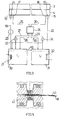
Ein in den Fig. 1 und 2 dargestelltes, zum Verschweißen von Folien vorgesehenes
Werkzeug weist einen ebenen, gemäß Pfeil 2 zur Anlage gegen eine der Folien vor
gesehenen Oberflächenabschnitt 1 auf. Wie Fig. 1 erkennen lässt, steht der Oberflächenabschnitt
1 vom Werkzeug geringfügig vor. Das längliche, sich in Richtung der
Schweißnaht erstreckende Werkzeug ist mehrteilig mit einem Werkzeugteil 3 und
einem Werkzeugteil 4 ausgebildet. Der Werkzeugteil 3 weist eine Ausnehmung 5 auf,
in welchen ein Vorsprung 6 des Werkzeugteils 4 hineinragt.An illustrated in FIGS. 1 and 2, provided for welding foils
Tool has a plane, according to arrow 2 for abutment against one of the slides
Seen
Zwischen dem Werkzeugteil 3 und dem Werkzeugteil 4 sind Hohlräume 7 bis 9 in Form
sich über die Länge des Werkzeugs erstreckender Kanäle gebildet. In die jeweiligen
Hohlräume 7 bis 9 hinein stehen von dem Werkzeugteil 3 jeweils Rippen 10 vor, die
sich über die gesamte Kanallänge erstrecken. Die freien, dem Werkzeugteil 3 abgewandten
Ränder der Rippen 10 enden in geringem Abstand von dem Vorsprung 6
des Werkzeugteils 4. Die Bezugszeichen 11 und 12 weisen auf Dichtungen hin.Between the
Es wird nun auf Fig. 3 Bezug genommen, in welcher das längliche Schweißwerkzeug
mit den Werkzeugteilen 3 und 4 in einer Seitenansicht zu sehen ist. Das Werkzeug
weist Einlässe 13 und 14 sowie Auslässe 15 und 16 auf, die mit dem Hohlraum 7 bzw. 9
verbunden sind. Ferner sind ein Einlass 17 und ein Auslass 18 für den Hohlraum 8 vorgesehen.Reference is now made to Fig. 3, in which the elongate welding tool
with the
Die Einlässe 13 und 14 stehen über eine sich verzweigende Leitung 19 in Verbindung
mit einem Vorratsbehälter 20 für ein Kühlmedium, das durch eine Kühlschlange 21
auf einer Temperatur T1 gehalten wird, welche in dem betreffenden Ausführungsbeispiel
20°C beträgt. Mit dem Vorratsbehälter 20 sind über eine Leitung 22 auch die
Auslässe 15 und 16 verbunden, so dass ein Kühlkreislauf gebildet ist, in welchem eine
Förderpumpe 23 das Kühlmedium im Umlauf hält.The
Das Bezugszeichen 24 weist auf ein in Fig. 4 gesondert dargestelltes Mehrwegventil
hin, das über eine Leitung 25 mit dem Einlass 17 und über eine Leitung 26 mit dem
Auslass 18 in Verbindung steht.The
Das Mehrwegventil 24 ist ferner über Leitungen 27 und 28 mit dem Vorratsbehälter 20
und über Leitungen 29 und 30 mit einem Vorratsbehälter 31 für ein Heizmedium verbunden.
Das Heizmedium wird durch ein Heizelement 32 auf einer Temperatur T2
gehalten, die in dem gezeigten Ausführungsbeispiel bei 200°C liegt. In den Leitungen
27 und 29 ist jeweils eine Förderpumpe 33 bzw. 34 vorgesehen.The
Heiz- und Kühlmedium stimmen in der stofflichen Zusammensetzung überein. In dem beschriebenen Ausführungsbeispiel handelt es sich bei den beiden Medien um ein hochsiedendes, bis zur maximalen Betriebstemperatur von 200°C flüssiges Öl.Heating and cooling medium agree in the material composition. By doing described embodiment is in the two media to a high-boiling, up to the maximum operating temperature of 200 ° C liquid oil.
Wie aus Fig. 4 hervorgeht, weist das Mehrwegventil 24 ein Gehäuse 35 und einen
Drehschieber 36 mit Durchgängen 37 bis 39 auf. Durch Drehung des Drehschiebers
36 im Uhrzeigersinn lassen sich die Durchgänge 37 bis 39 derart anordnen, dass
gemäß Fig. 4a die Leitungen 27 und 28 unter Bildung eines Kühlkreislaufs mit den
Leitungen 25 und 26 und gemäß Fig. 4c die Leitungen 29 und 30 unter Bildung eines
Heizkreislaufs mit den Leitungen 25 und 26 verbindbar sind. Im ersten Fall sind die
Leitungen 29 und 30 und im zweiten Fall die Leitungen 27 und 28 kurzgeschlossen, so
dass Kühlmedium bzw. Heizmedium durch die Pumpe 33 bzw. 34 im Umlauf gehalten
werden kann.As is apparent from Fig. 4, the
Fig. 4b zeigt eine Zwischenstellung, die schnell durchfahren wird.Fig. 4b shows an intermediate position, which is traversed quickly.
Über eine Verbindungsleitung 45 kann ein Füllmengenausgleich zwischen den Behältern
20 und 31 erfolgen, der notwendig ist, wenn, wie im vorliegenden Fall, im Heizkreislauf
ein höherer Förderdruck als im Kühlkreislauf herrscht und über das Ventil 24
Kühlmedium in den Heizkreislauf übertritt. Via a connecting
Anhand von Fig. 5 und 6 wird nun die Wirkungsweise der vorangehend beschriebenen Vorrichtung erläutert.With reference to FIGS. 5 and 6, the operation of the previously described will now be Device explained.
Um gemäß Fig. 5 Folien 40 und 41 miteinander zu verschweißen, werden zwei Werkzeuge
gemäß Fig. 1 und 2 mit ihren Oberflächenabschnitten 1 einander gegenüberliegend
angeordnet und unter leichtem Druck gegen die Folie 40 bzw. 41 angelegt.In order to weld foils 40 and 41 together according to FIG. 5, two tools are used
according to Fig. 1 and 2 with their
Fig. 6 zeigt eine auf dem Oberflächenabschnitt 1 in Richtung X der Koordinate vor
dem Schweißen herrschende Temperaturverteilung. In einem Abschnitt 42, dessen
Breite etwa der Breite des Hohlraums 8 entspricht, hat sich eine Temperatur T2' eingestellt,
die etwas unterhalb der Vorlauftemperatur T2 im Vorratsbehälter 31 liegt. Heizmedium
aus dem Vorratsbehälter 31 durchströmt den Hohlraum 8.Fig. 6 shows a temperature distribution prevailing on the
Außerhalb des Abschnitts 42 herrscht in dem Oberflächenabschnitt 1 eine niedrigere
Temperatur T1', die etwas oberhalb der Temperatur T1 im Vorratsbehälter 20 liegt.Outside the section 42 prevails in the
Durch die erhöhte Temperatur im Abschnitt 42 kommt es bei 43 zum Fließen des
Materials der Folien 40 und 41 und schließlich zu einer Verbindung der Folien. In
diesem Zustand haften die Werkzeuge an der Folie 40 bzw. 41 an und lassen sich
nicht ohne weiteres davon lösen. Während eines Schweißzyklus' wird daher der Drehschieber
36 des Mehrwegventils 24 in die in Fig. 4a gezeigte Stellung gedreht, wodurch
der Hohlraum 8 von dem dem Vorratsbehälter 31 enthaltenden Heizkreislauf
getrennt und in einen den Vorratsbehälter 20 enthaltenden Kühlkreislauf eingebunden
wird. Im Abschnitt 42 kommt es nun schnell zur Abkühlung auf die Temperatur
T2'' kommt. Damit kühlen sich auch die bei 43 verschweißten Folien 40 und 41 ab und
die Werkzeuge lassen sich davon lösen.Due to the elevated temperature in the section 42, the flow of the material of the
Zur Vorbereitung eines nächsten Schweißzyklus' wird der Drehschieber 36 wieder in
die in Fig. 4c gezeigte Stellung gedreht. Der Hohlraum 8 ist nun wieder in den Heizkreislauf
eingebunden. Es stellt sich im Bereich 42 wieder die Temperatur T2' als Ausgangstemperatur
für einen folgenden Schweißzyklus ein.In preparation for a next welding cycle, the
Die Temperatur T1' bleibt während der Schweißzyklen annähernd konstant, was
einerseits auf die hohe Wärmekapazität des Werkzeugteils 3 in seinen an den Hohlraum
8 grenzenden Bereichen und andererseits auf die wirksame Kühlung durch das
die Hohlräume 7 und 9 durchströmende Kühlmedium aus dem Vorratsbehälter 20
zurückzuführen ist. The temperature T 1 'remains approximately constant during the welding cycles, which is due on the one hand to the high heat capacity of the
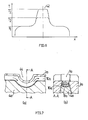
Es wird nun auf Fig. 7 Bezug genommen, wo gleiche oder gleichwirkende Teile mit derselben Bezugszahl wie in den vorangehenden Figuren bezeichnet sind, wobei der betreffenden Bezugszahl der Buchstabe a beigefügt ist.Reference is now made to Fig. 7, where the same or equivalent parts with the same reference number as in the preceding figures, wherein the (a) is attached to the relevant reference number.
Ein in Fig. 7 teilweise dargestelltes Werkzeug unterscheidet sich von dem Werkzeug
gemäß Fig. 1 und 2 dadurch, dass in einen im übrigen ebenen Oberflächenabschnitt
1 a eine Vertiefung 44 mit halbkreisförmigem Querschnitt eingearbeitet ist. Dieses
Werkzeug mit seinem der Werkstückkontur angepassten Oberflächenabschnitt 1 a
eignet sich zur Herstellung von Folienbeuteln, wobei Folien miteinander unter Einschluss
eines Anschlussschlauches und Verbindung mit dem Anschlussschlauch zu
verschweißen sind. Dabei kommt der Anschlussschlauch innerhalb der Vertiefung 44
zur Anordnung.A partially illustrated in Fig. 7 tool is different from the tool
according to Fig. 1 and 2 characterized in that in an otherwise
Wie auch bei dem vorangehenden Ausführungsbeispiel sitzen bei Belastung des
Werkzeugs die Rippen 10a auf dem Werkzeugteil 4a auf, so dass die verhältnismäßig
dünne Materiallage zwischen dem Oberflächenabschnitt 1 a und dem Hohlraum 8a
nicht deformiert wird.As in the previous embodiment sitting under load of
Tool the
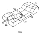
Fig. 8 zeigt einen Werkzeugteil 3b mit einem räumlich gekrümmten Oberflächenabschnitt
1 b und in einen Hohlraum 8b vorstehenden Rippen 10b. Wie ein Ausschnitt bei
45 erkennen lässt, ist der Abstand zwischen den Rippen in einem mittleren Bereich
des Werkzeugteils vergrößert.Fig. 8 shows a
Claims (11)
dadurch gekennzeichnet, dass die Einrichtungen zur impulsweisen Aufheizung der Werkzeugoberflächen einen nahe dem Oberflächenabschnitt (1) angeordneten Hohlraum (8) zur Durchströmung mit einem Heizmedium umfassen.Apparatus for welding, hot embossing or heat sealing of plastic parts, in particular plastic films (40, 41), with a tool (3, 4) having a surface section (1) provided for abutment against a plastic part, and with means for impulse heating of the tool surface in the surface portion (1),
characterized in that the means for pulsed heating of the tool surfaces comprise a near the surface portion (1) arranged cavity (8) for flow through with a heating medium.
gekennzeichnet durch Einrichtungen zur aufeinanderfolgenden Durchströmung des Hohlraums (8) mit dem Heizmedium und einem Kühlmedium.Device according to claim 1,
characterized by means for successively flowing the cavity (8) with the heating medium and a cooling medium.
dadurch gekennzeichnet, dass Einrichtungen zur unmittelbar aufeinanderfolgenden Durchströmung mit dem Heiz- und Kühlmedium derart vorgesehen sind, dass sich die Medien jeweils gegenseitig aus dem Hohlraum (8) verdrängen.Device according to claim 2,
characterized in that means are provided for directly successive flow with the heating and cooling medium such that the media displace each other from the cavity (8).
dadurch gekennzeichnet, dass auch das Kühlmedium eine Flüssigkeit ist.Device according to claim 2 or 3,
characterized in that the cooling medium is a liquid.
dadurch gekennzeichnet, dass das Heizmedium und das Kühlmedium in ihrer stofflichen Zusammensetzung übereinstimmen.Device according to one of claims 2 to 4,
characterized in that the heating medium and the cooling medium in their material composition coincide.
dadurch gekennzeichnet, dass das Heizmedium und/oder das Kühlmedium ein hochsiedendes Öl ist. Device according to one of claims 2 to 5,
characterized in that the heating medium and / or the cooling medium is a high-boiling oil.
dadurch gekennzeichnet, dass die Aufheizung auf einen Teil (42) des Oberflächenabschnitts (1) konzentriert ist.Device according to one of claims 1 to 6,
characterized in that the heating is concentrated on a part (42) of the surface portion (1).
dadurch gekennzeichnet, dass Einrichtungen (7,9) zur Kühlung eines den aufgeheizten Teil (42) umgebenden Teils des Oberflächenabschnitts (1) vorgesehen sind.Device according to claim 7,
characterized in that means (7, 9) are provided for cooling a portion of the surface portion (1) surrounding the heated part (42).
dadurch gekennzeichnet, dass von einem dem Oberflächenabschnitt (1) gegenüberliegenden Wandabschnitt des Hohlraums (8) in den Hohlraum (8) hinein Rippen (10) vorstehen.Device according to one of claims 1 to 8,
characterized in that ribs (10) protrude into the cavity (8) from a wall section of the cavity (8) opposite the surface section (1).
dadurch gekennzeichnet, dass das Werkzeug (3,4) mehrteilig ausgebildet ist, wobei der freie Rand der von einem Werkzeugteil (3) vorstehenden Rippen (10) in derart geringem Abstand von einem anderen Werkzeugteil (4) endet, dass bei Belastung des Oberflächenabschnitts (1) die Rippen (10) an ihrem freien Rand durch das andere Werkzeugteil (4) abgestützt sind.Device according to claim 9,
characterized in that the tool (3, 4) is designed in several parts, the free edge of the tool part (3) projecting ribs (10) ends at such a small distance from another tool part (4), that when loading the surface portion ( 1) the ribs (10) are supported at their free edge by the other tool part (4).
dadurch gekennzeichnet, dass ein Heizkreislauf und ein Kühlkreislauf mit unterschiedlichem Förderdruck betreibbar sind und Einrichtungen (45) zum Ausgleich des Füllstands in einem Vorratsbehälter (20) des Kühlkreislaufs und einem Vorratsbehälter (31) des Heizkreislaufs bestehen.Device according to one of claims 1 to 10,
characterized in that a heating circuit and a cooling circuit with different delivery pressure are operable and means (45) for balancing the level in a reservoir (20) of the cooling circuit and a reservoir (31) of the heating circuit exist.
Applications Claiming Priority (2)
| Application Number | Priority Date | Filing Date | Title |
|---|---|---|---|
| DE102004010022 | 2004-03-02 | ||
| DE102004010022A DE102004010022A1 (en) | 2004-03-02 | 2004-03-02 | Device for welding, hot stamping or heat sealing of plastic parts |
Publications (2)
| Publication Number | Publication Date |
|---|---|
| EP1570975A2 true EP1570975A2 (en) | 2005-09-07 |
| EP1570975A3 EP1570975A3 (en) | 2008-01-23 |
Family
ID=34745335
Family Applications (1)
| Application Number | Title | Priority Date | Filing Date |
|---|---|---|---|
| EP05003982A Withdrawn EP1570975A3 (en) | 2004-03-02 | 2005-02-24 | Apparatus for heat welding or heat embossing of plastic parts |
Country Status (2)
| Country | Link |
|---|---|
| EP (1) | EP1570975A3 (en) |
| DE (1) | DE102004010022A1 (en) |
Citations (9)
| Publication number | Priority date | Publication date | Assignee | Title |
|---|---|---|---|---|
| US2466735A (en) * | 1946-10-23 | 1949-04-12 | Shellmar Products Corp | Heat-sealing device |
| GB1158228A (en) * | 1967-01-12 | 1969-07-16 | Leon Doyen | Improvement in Welding Machines for Thermoplastic Materials. |
| DE1927199A1 (en) * | 1969-05-28 | 1970-12-03 | Willi Kopp Maschb | Welding die for impulse welding sheets of - polyethylene |
| US4062718A (en) * | 1976-09-02 | 1977-12-13 | The Dow Chemical Company | Heat sealing means |
| US4792374A (en) * | 1987-04-03 | 1988-12-20 | Georg Fischer Ag | Apparatus for fusion joining plastic pipe |
| EP0314970A1 (en) * | 1987-11-06 | 1989-05-10 | Georg Fischer Aktiengesellschaft | Method and device for lining a connecting end of compound pipeline components |
| WO1990000112A2 (en) * | 1988-07-04 | 1990-01-11 | Georg Fischer Ag | Device for welding tubular plastic elements |
| WO1990011884A1 (en) * | 1989-04-08 | 1990-10-18 | Armin Dommer | Process and device for butt-welding two plastics pipe sections or two shaped plastics articles |
| EP0566338A1 (en) * | 1992-04-10 | 1993-10-20 | Kaysersberg Packaging S.A. | Method for sealing the edge of fluted plastic boards |
-
2004
- 2004-03-02 DE DE102004010022A patent/DE102004010022A1/en not_active Withdrawn
-
2005
- 2005-02-24 EP EP05003982A patent/EP1570975A3/en not_active Withdrawn
Patent Citations (10)
| Publication number | Priority date | Publication date | Assignee | Title |
|---|---|---|---|---|
| US2466735A (en) * | 1946-10-23 | 1949-04-12 | Shellmar Products Corp | Heat-sealing device |
| GB1158228A (en) * | 1967-01-12 | 1969-07-16 | Leon Doyen | Improvement in Welding Machines for Thermoplastic Materials. |
| DE1927199A1 (en) * | 1969-05-28 | 1970-12-03 | Willi Kopp Maschb | Welding die for impulse welding sheets of - polyethylene |
| US4062718A (en) * | 1976-09-02 | 1977-12-13 | The Dow Chemical Company | Heat sealing means |
| US4792374A (en) * | 1987-04-03 | 1988-12-20 | Georg Fischer Ag | Apparatus for fusion joining plastic pipe |
| US4792374B1 (en) * | 1987-04-03 | 1995-02-14 | Fischer Ag Georg | Apparatus for fusion joining plastic pipe |
| EP0314970A1 (en) * | 1987-11-06 | 1989-05-10 | Georg Fischer Aktiengesellschaft | Method and device for lining a connecting end of compound pipeline components |
| WO1990000112A2 (en) * | 1988-07-04 | 1990-01-11 | Georg Fischer Ag | Device for welding tubular plastic elements |
| WO1990011884A1 (en) * | 1989-04-08 | 1990-10-18 | Armin Dommer | Process and device for butt-welding two plastics pipe sections or two shaped plastics articles |
| EP0566338A1 (en) * | 1992-04-10 | 1993-10-20 | Kaysersberg Packaging S.A. | Method for sealing the edge of fluted plastic boards |
Also Published As
| Publication number | Publication date |
|---|---|
| DE102004010022A1 (en) | 2005-09-22 |
| EP1570975A3 (en) | 2008-01-23 |
Similar Documents
| Publication | Publication Date | Title |
|---|---|---|
| DE69530243T2 (en) | liquid applicator | |
| DE102014223550B4 (en) | Device and method for producing milk foam | |
| DE2255866B2 (en) | Extrusion press | |
| EP3731973A1 (en) | Application nozzle | |
| DE3008779C2 (en) | Melting and application device for hot melt adhesive | |
| DE2523894C3 (en) | Hydraulic servo motor system | |
| DE1525512A1 (en) | Process for the automatic cleaning of an endless pipe and arrangement for carrying out this process | |
| DE102007048046A1 (en) | Apparatus and method for dispensing a fluid, in particular hot-melt adhesive | |
| DE202017106063U1 (en) | Contact welding heating component and automatic welding machine | |
| EP0227060B1 (en) | Filling wedge for an apparatus making gelatin capsules | |
| EP1570975A2 (en) | Apparatus for heat welding or heat embossing of plastic parts | |
| AT519283B1 (en) | METHOD FOR PRODUCING PLASTIC PROFILES | |
| EP3104917A1 (en) | Device for heating flowing fluids | |
| DE8607997U1 (en) | Heating device, in particular for motor vehicles | |
| DE102005005924B4 (en) | Apparatus for dispensing paint for bonding substrate disks | |
| EP0841634A2 (en) | Method for manufacturing a chip card and device for implementing the method | |
| EP1685894A2 (en) | Venturi mixing nozzle | |
| DE102005041191B4 (en) | Device for joining at least two parts | |
| DE4223595C1 (en) | Prodn. of electrical self regulating heating unit - connecting PTC elements to heat dissipating elements on both sides by adhesive and making drillings in adhesion region before pressing elements together | |
| AT522426B1 (en) | Distribution block | |
| DE3420206A1 (en) | DEVICE FOR COVERING CONFECTIONERY ITEMS | |
| EP3511645B1 (en) | Electric heating device | |
| DE4212335C2 (en) | Extrusion device for the production of plates | |
| EP4317887A1 (en) | Cooling body comprising a pulsating heat pipe | |
| DE19742711C1 (en) | Device for applying adhesive dots on a substrate |
Legal Events
| Date | Code | Title | Description |
|---|---|---|---|
| PUAI | Public reference made under article 153(3) epc to a published international application that has entered the european phase |
Free format text: ORIGINAL CODE: 0009012 |
|
| AK | Designated contracting states |
Kind code of ref document: A2 Designated state(s): AT BE BG CH CY CZ DE DK EE ES FI FR GB GR HU IE IS IT LI LT LU MC NL PL PT RO SE SI SK TR |
|
| AX | Request for extension of the european patent |
Extension state: AL BA HR LV MK YU |
|
| PUAL | Search report despatched |
Free format text: ORIGINAL CODE: 0009013 |
|
| AK | Designated contracting states |
Kind code of ref document: A3 Designated state(s): AT BE BG CH CY CZ DE DK EE ES FI FR GB GR HU IE IS IT LI LT LU MC NL PL PT RO SE SI SK TR |
|
| AX | Request for extension of the european patent |
Extension state: AL BA HR LV MK YU |
|
| AKX | Designation fees paid | ||
| STAA | Information on the status of an ep patent application or granted ep patent |
Free format text: STATUS: THE APPLICATION IS DEEMED TO BE WITHDRAWN |
|
| 18D | Application deemed to be withdrawn |
Effective date: 20080726 |
|
| REG | Reference to a national code |
Ref country code: DE Ref legal event code: 8566 |