EP1570937B1 - Einrichtung zum Kurzschluss-Lichtbogenschweissen - Google Patents
Einrichtung zum Kurzschluss-Lichtbogenschweissen Download PDFInfo
- Publication number
- EP1570937B1 EP1570937B1 EP04023284A EP04023284A EP1570937B1 EP 1570937 B1 EP1570937 B1 EP 1570937B1 EP 04023284 A EP04023284 A EP 04023284A EP 04023284 A EP04023284 A EP 04023284A EP 1570937 B1 EP1570937 B1 EP 1570937B1
- Authority
- EP
- European Patent Office
- Prior art keywords
- waveform
- arc
- voltage
- current
- welder
- Prior art date
- Legal status (The legal status is an assumption and is not a legal conclusion. Google has not performed a legal analysis and makes no representation as to the accuracy of the status listed.)
- Expired - Lifetime
Links
Images


Classifications
-
- B—PERFORMING OPERATIONS; TRANSPORTING
- B23—MACHINE TOOLS; METAL-WORKING NOT OTHERWISE PROVIDED FOR
- B23K—SOLDERING OR UNSOLDERING; WELDING; CLADDING OR PLATING BY SOLDERING OR WELDING; CUTTING BY APPLYING HEAT LOCALLY, e.g. FLAME CUTTING; WORKING BY LASER BEAM
- B23K9/00—Arc welding or cutting
- B23K9/09—Arrangements or circuits for arc welding with pulsed current or voltage
- B23K9/091—Arrangements or circuits for arc welding with pulsed current or voltage characterised by the circuits
- B23K9/093—Arrangements or circuits for arc welding with pulsed current or voltage characterised by the circuits the frequency of the pulses produced being modulable
-
- B—PERFORMING OPERATIONS; TRANSPORTING
- B23—MACHINE TOOLS; METAL-WORKING NOT OTHERWISE PROVIDED FOR
- B23K—SOLDERING OR UNSOLDERING; WELDING; CLADDING OR PLATING BY SOLDERING OR WELDING; CUTTING BY APPLYING HEAT LOCALLY, e.g. FLAME CUTTING; WORKING BY LASER BEAM
- B23K9/00—Arc welding or cutting
- B23K9/06—Arrangements or circuits for starting the arc, e.g. by generating ignition voltage, or for stabilising the arc
- B23K9/073—Stabilising the arc
-
- B—PERFORMING OPERATIONS; TRANSPORTING
- B23—MACHINE TOOLS; METAL-WORKING NOT OTHERWISE PROVIDED FOR
- B23K—SOLDERING OR UNSOLDERING; WELDING; CLADDING OR PLATING BY SOLDERING OR WELDING; CUTTING BY APPLYING HEAT LOCALLY, e.g. FLAME CUTTING; WORKING BY LASER BEAM
- B23K9/00—Arc welding or cutting
- B23K9/095—Monitoring or automatic control of welding parameters
-
- B—PERFORMING OPERATIONS; TRANSPORTING
- B23—MACHINE TOOLS; METAL-WORKING NOT OTHERWISE PROVIDED FOR
- B23K—SOLDERING OR UNSOLDERING; WELDING; CLADDING OR PLATING BY SOLDERING OR WELDING; CUTTING BY APPLYING HEAT LOCALLY, e.g. FLAME CUTTING; WORKING BY LASER BEAM
- B23K2101/00—Articles made by soldering, welding or cutting
- B23K2101/04—Tubular or hollow articles
- B23K2101/10—Pipe-lines
Definitions
- the invention relates to the art of arc welding and more particularly to an electric arc welder having a unique controller for performing short circuit electric arc welding.
- Electric arc welding is performed in a variety of processes, such as spray welding, globular welding, and short circuit welding. Irrespective of the process employed, an inverter converts three phase line current to the desired voltage or current.
- An inverter based power supply for electric arc welding has a digitally based control to produce a desired output current or voltage at the arc welding process.
- pulse welding or short circuit welding is preferred for the first weld bead, known as the "root pass", that closes the open gap between edges of adjacent workpieces.
- the short circuit electric arc welding procedure is implemented by using the patented STT technology. In this technology, a precise current waveform is outputted by the power supply.
- the current waveform produces a plasma boost for melting the end of the electrode awaiting the next short.
- the peak current of the plasma boost pulse is gradually reduced in a current tailout until a set background current is reached. Thereafter, the background current is maintained until the molten metal ball shorts against the workpiece causing the next cycle.
- the current waveform is accurately controlled by a series of current pulses, the widths of which determine the magnitude of the current at any given time in the waveform.
- the shape of the waveform is controlled by a waveform generator. By using this technique, the current waveform allows control of the puddle temperature and/or fluidity.
- EP 1 232 825 A2 discloses a short circuit arc welder and method of controlling same.
- the electric arc welder is operated to perform a short circuit process with a first waveform controlling a short condition followed by a second waveform controlling an arc condition, the second waveform having a decaying part.
- an electric arc welder that can function in the STT mode where heat is controlled merely by changing the position of the electrode.
- the invention is a controller that generates a voltage waveform for the arc portion or condition of a short circuit welding process. Consequently, the power supply is operable in both current and voltage control modes so current control is used when best for the short circuit condition of the welding cycle, while voltage control is used for the plasma or arc condition. Consequently, the current mode of the power supply will use a waveform control that is the same as the STT welder to implement the short circuit condition of the welding cycle.
- a controlled pinch current waveform is implemented.
- a dv/dt, dr/dt or dt/dt detector determines an impending break or separation of metal from the electrode. Then, a power switch is opened to instantaneously reduce current flow before the electrode separates. This action minimizes spatter.
- the short is broken, the arc condition or plasma condition is immediately established.
- the power supply electronics detects the break in the electrode as an increase in arc voltage.
- the power supply shifts into the voltage control phase.
- a voltage waveform is generated to provide a constant arc parameter until the next short circuit is detected to shift the waveform back to a current control for clearing the short circuit.
- current will change due to the desired constant voltage of the voltage waveform. If the voltage control circuitry is precise and the extension length maintained reasonably constant, the welding current will be reasonably constant during the arc or plasma condition.
- the voltage controlled portion of the welding process has no tailout or a set background voltage to which the voltage transitions to await the next short circuit.
- the weld puddle temperature and fluidity can be accurately controlled to optimize the welding process and operate in the voltage range of the power supply.
- This novel technique of using a current waveform during the short circuit condition and a constant voltage waveform during the arc condition is applicable in any short circuit electric arc welding process.
- the invention merely involves using a controlled constant voltage waveform during the arc or plasma condition of a short circuit welding process.
- the short condition of the welding process can be controlled in accordance with standard technology or by the precision current waveform used in the STT technology.
- Such technology uses a switch, such as a Darlington switch, to plung the short circuit current upon the detection of an imminent break in the metal, known as a "neck.”
- the invention can be used in a modified short circuit process where the switch and "neck" control is not used.
- the basic aspect of the invention is the current implementation of the short circuit condition with a precision constant voltage waveform for the arc or plasma condition of the welding process.
- an electric arc welder operated to perform a short circuit process with a first waveform controlling a short condition followed by a second waveform controlling the arc condition.
- the welder comprises a comparator to create an arc signal when the short condition terminates.
- a controller then shifts the welder from control by the first waveform to control by the second waveform.
- the second waveform is a precise constant voltage waveform wherein the first waveform is a current waveform which may be somewhat conventional. This is preferably either an STT process or a modified STT process without a premonition circuit.
- the first waveform is a current controlled waveform and the second waveform is a voltage controlled waveform with a constant voltage.
- the second waveform is sometimes a constant wattage control waveform or a constant joules control waveform. Both of these complex parameters are functions of the arc voltage.
- the waveforms are implemented as a series of current pulses that define either the current waveform or the constant voltage waveform of the invention.
- FIG. 1 shows an STT type waveform A for a short circuit welding process including a short condition 10, and an arc condition 12 with constant parameter, shown as a constant voltage.
- This waveform is the current profile through the weld and is formed by a plurality of current pulses 20 created at a frequency exceeding 18 kHz. The widths of the current pulses control the magnitude or height of the waveform as illustrated in FIG. 1 .
- Short circuit welding includes alternating between an arc or plasma condition 12 and a short condition 10 initiated at the time a molten metal ball on the end of an electrode contacts the workpiece. This event occurs at time 30.
- Metal is then transferred from the electrode to the workpiece by surface tension action.
- This action is accelerated by pinch pulse 32 used to control the current with a profile having a rapidly increasing current section 32a, a break point 32b to give a second slope, and a premonition point 32c.
- a dv/dt, dr/dt or dp/dt circuit detects when the surface tension transfer of molten metal is ready to separate or explode. At that time, the voltage increases because the cross section decreases rapidly. This event anticipates the explosion or separation of the molten electrode tip from the workpiece.
- the waveform includes a current plunge section 32d before actual metal separation.
- Current pinch pulse 32 is controlled in the STT technology by the shape of pinch pulse 32 shown in FIG. 1 . Thereafter, there is a slight delay 34 indicated to be time t x before the current rapidly increases to create plasma pulse 40. In the STT technology, this rapid increase in current is toward a fixed peak current.
- the controller shifts the power supply between current control during the short condition and to voltage control during the arc condition 12. This causes a current increase in the plasma constant parameter pulse 40 of a voltage function.
- Such a constant voltage waveform of FIG. 1 normally produces a generally constant current. The desired amount of energy is transmitted to create a molten metal ball awaiting a shot at time 30.
- the waveform implemented during arc condition 12 is a voltage waveform having a constant voltage V P and then a short circuit. At the end of the constant voltage waveform, there is a new short at time 30 causing the voltage to plunge and shift the power supply to a current control for the pinch pulse 32.
- the invention involves using current control during the short condition 10 and voltage control during arc position 12. In each instance, these controls follow predetermined waveforms to produce the desired characteristics. Consequently, the arc condition 12 is a voltage function. In the preferred embodiment, the voltage function is the voltage across the arc. As will be explained later, a standard closed loop control operated during the short condition to create a desired presized, preselected waveform during condition 10, shown as waveform 100 in FIG. 3 . The same concept, i.e. current control during the short condition and voltage function control during condition 12', is used in the second embodiment of the invention illustrated in FIG. 2 .
- Waveform A' includes a short condition 10' and an arc condition 12'.
- the voltage function used during condition 12' for closed loop control is wattage.
- the plasma pulse 40' is a constant waveform 150 as shown in FIG. 3 .
- the voltage function is sometimes joules, so a joules closed loop feedback produces a waveform as shown in FIG.s 1 and 2 .
- Utilizing a pulse width modulated, inverter based power supply of the type used in the preferred embodiment of the present invention results in the current and voltage curves schematically illustrated in FIG. 3 .
- Current waveform 100 in the classic STT form plunges at time 30 when the molten metal ball is shorted to the workpiece causing the voltage to plunge. Such voltage decrease is to a level less than a reference voltage V R causing the power supply to shift from voltage control of plasma condition 12 to current control of short circuit condition 12.
- Current control implements the short circuit condition of the weld cycle. The current is held down for a short time until the current is allowed to increase.
- current control of the power supply is then released allowing a rapid increase in the current at position 32a to create pinch pulse 32 having a break point 326 and a premonition point 32c.
- the current control of the power supply plunges the current as indicated by portion 32d.
- the explosion or metal separation occurs at the low current 34 that is maintained for a time t a .
- the current mode of operation allows an increase in voltage to create current pulse 40 which current has a waveform 150 dictated by the predesigned constant voltage control waveform.
- Current pulse 40 has a steep, leading edge while current is advancing toward the constant level of pulse 40. This current level is caused by the set peak voltage portion of waveform150 used during voltage control of the power supply.
- Pulse 40 is a current pulse with a shape dictated by the desired voltage waveform 150 shown in FIG. 3 .
- Current control defines pulse 10 with waveform 100 and voltage control defines pulse 40 with waveform 150.
- the voltage control experiences a short circuit and control is shifted from voltage to current.
- a low current is maintained until time 32a.
- Current pulse 10 is then created by the desired current waveform 100.
- the power supply maintains the desired shape of pinch pulse 32. Voltage immediately rises along portion 160a as a result of the desired current.
- break point 32b the voltage transitions along the top line until portion 32c where the voltage is plunged along line 32din response to the standard premonition signal. This is still in the current control mode.
- the shorted electrode separates at time 32d, causing the voltage to increase to a level above reference V R causing the power supply to shift to a voltage control waveform 150 as the arc voltage obtained when arc is re-established at low current 34.
- This next waveform 150 includes constant voltage 42. To reach the peak voltage 42, there is a short time. This short time plus the actual delay equals the previously discussed delay 34 having a time T x .
- This control is standard practice in STT welders. After processing of the voltage waveform 150 to melt the electrode, voltage 42 is held awaiting the next short circuit. In practice, 100 to 300 cycles of pulses shown in FIG. 3 are performed each second. By adjusting constant voltage 42, the temperature and/or fluidity of the weld puddle is controlled.
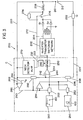
- welder 200 has a logic processor based controller C programmable to implement a short circuit arc welding process, such as an STT short circuit welding process.
- Inverter 202 has a standard rectified output circuit 204 for directing current through switch 206 and inductor 208 to electrode 210 in the form of an advancing wire used to weld workpiece 214.
- Voltage feedback 220 directs the level of the arc voltage back to digital controller C.
- shunt 222 directs the instantaneous arc current back to controller C by feedback line 224.
- the logic processor in controller C includes a digitally implemented pulse width modulator 230 having an input digitized error amplifier 234 with a waveform control represented by line 240.
- Pulse width modulator 230 causes inverter 202 to follow the waveform on line 240 based upon the feedback value in line 242.
- current waveform generator 250 is provided to give the desired profile of the current pulse between the electrode and workpiece during various portions of the weld cycle.
- Oscillator 232 is set at a frequency of at least 18 kHz so pulses in line 233 have this high frequency.
- current waveform generator 250 is used by pulse modulator 230 for only a portion of the time or segment of the weld cycle as determined by the conductive state of digital enable switch 252.
- generator 250 controls the logic on line 240 so that the feedback level on line 242 follows the desired precise current profile or waveform 100 shown as a standard STT waveform as used in the field.
- a voltage waveform generator 260 is also provided to generate a constant waveform 150.
- Generator 260 has an output directed through digital enable switch 262 to input 240. Switch 252 and switch 262 are anti-coincident. When one enable switch is closed, the other enable switch is opened.
- error amplifier 234 receives a waveform generated from either the current waveform generator 250 or the voltage waveform generator 260 (waveform 150), according to the conductive condition of switch 252, 262.
- a premonition circuit 270 indicated as a dv/dt circuit, creates a logic in line 272 for opening switch 206 when the metal transfer is near the breaking point.
- Resistor 274 is then inserted into the weld circuit to reduce current along portion 32c.
- a digitized comparator 280 has a positive input 282 connected with the voltage feedback 220 and a negative input 284 controlled by reference voltage V R .
- Output line 290 of comparator 280 is connected to a voltage mold digital switch 292.
- the logic on line 290 is inverted by inverter 294 to provide the opposite logic on line 296 for controlling current mode switch 298.
- inverter 294 produces a logic 1 in line 296. This activates switch 298 so the current feedback level in line 224 is directed to input 242 of error amplifier 234.
- the logic 1 on line 296 enables digital switch 252 so waveform generator 250 is connected to input 240 of the error amplifier.
- the inverter 220 follows waveform 100 from generator 250. At the end of the short, the arc voltage increases rapidly.
- inverter 202 follows waveform 150 of constant voltage waveform 150 created by generator 260.
- This generator could also be a constant wattage waveform generator or a constant joules waveform generator. All of these iterations have been practiced to control the arc condition of the short circuit welding process.
- controller C is processed by digital technology in controller C and a variety of digital techniques can be used to accomplish the objective of generally operating the arc condition by a waveform tracking the desired function of voltage as a constant plasma parameter.
- the waveform during the arc condition has been merely an extension of the short circuit waveform so that the advantage of controlling the arc as a voltage function was not available.
- a digital switch is employed where the logic processor opens line 290 by a switch 290a illustrated in FIG. 3A .
- This two pole switch concept grounds line 290b by ground 290c. This places a logic zero on line 290b to shift the switches to current control.
- This switch action is selected by the logic processor after a molten ball is formed by the plasma pulse 40.
- FIG.s 4 and 5 illustrate slight modifications of the block diagram and logic chart of FIG. 3 .
- the voltage function is constant wattage; therefore, the inputs of line 282 of comparator 280 is the product of the voltage feedback on line 220 and current feedback on line 224. These values are combined by the multiplier 210 to produce a value in line 312 representing the wattage feedback.
- the current feedback 224 is used at the input of switch 298 as previously shown in FIG. 3 .
- the arc condition has a constant wattage waveform controlled by a wattage feedback, while the short condition is controlled as shown in FIG. 3 by a current feedback.
- FIG. 4 the voltage function is constant wattage; therefore, the inputs of line 282 of comparator 280 is the product of the voltage feedback on line 220 and current feedback on line 224. These values are combined by the multiplier 210 to produce a value in line 312 representing the wattage feedback.
- the current feedback 224 is used at the input of switch 298 as previously shown in FIG.
- the product in line 312 is integrated by integrator 320 to produce a joules feedback in line 322. This is directed to the positive input 282 of comparator 280 and to the input of switch 292 so the arc condition is controlled by a constant joules waveform that is a precise reflection of the desired joules waveform 150.
- Other such changes in the digital processing schematically illustrated in FIG. 3 can be used so long as the pulse portion of the arc condition is controlled by a waveform 150 that is a precise representation of a desired voltage function. The voltage rating of the CV power source will not be exceeded by anomalies in the welding process.
- the modified welder 200' is a modified STT welder wherein Darlington switch 206 and the neck premonition circuit 270 are removed.
- This modified circuit produces the waveform as shown in FIG.s 6 and 7 with the same numbers as corresponding portions of waveforms illustrated in FIG.s 1 and 2 , respectively.
- inductor 208 controls the drop in current from the bread point 32c to the constant voltage waveform 40 to shift along the rapid time constant curve 400.
- This is a modified STT curve.
- the shift at the short circuit condition 30 is along a time constant curve 402.
- inverter 500 or an equivalent chopper has waveforms controlled by pulse width modulator 502 operated at a frequency in excess of 18 kHz by oscillator 504.
- Error amplifier 510 has a feedback input 512 from the arc current sensing device and a control input 514 connected to waveform generator 250 by line 514a and generator 260 by line 514b.
- the arc voltage on line 282 determines the profile of the waveform is being transmitted to pulse width modulator 502.
- the premonition circuit overrides the shift to a plasma condition. It occurs in advance of the arc condition.
- the logic on line 282 controls the particular waveform 100 or 150 being processed by inverter 500. This general system is used in performing the welding processes shown in FIG.s 1, 2 and 6, 7 .
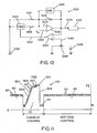
- FIG.s 10 and 11 A further aspect of the invention is shown in FIG.s 10 and 11 where the two slope configuration waveform 100 is shown in more detail.
- This waveform is used in a welder wherein waveform 100 is current control and waveform 150 is controlled differently, i.e. by voltage.
- circuit 520 includes integrator amplifier 522 controlled by discharge of capacitor 524 when switch 526 is open indicating there is no arc. This is during waveform 100.
- Capacitor 524 is discharged through resistor 530 to ground 532 during the first portion 550 of waveform 100 as shown in FIG. 11 .
- Integrator 522 has an input reference 540 and a control input 542.
- the integrator assures first portion 550 is generally a straight line as capacitor 524 discharges.
- comparator 560 provides a signal in line 562 to close switch 564. This places resistor 566 in parallel with resistor 530 to increase the discharge rate of capacitor 524.
- the slope of portion 552 is reduced, as shown in FIG. 11 .
- Current waveform 100 is terminated by a necking signal in line 272 or by the current on line 544 reaching a set value, normally 550 amperes. This is done by a standard maximum current circuit not shown. By using the two.slope current pulse, the use of a constant voltage pulse waveform 150 does not affect the short circuit control of the arc welder.
- the electric arc welder using waveform technology has a current break point adjusting circuit 600 as shown schematically in FIG. 12 .
- a standard manually adjusting element 548 uses rheostat 602 to input a break point level signal into circuit 610 by line 612.
- set point 32b is manually adjusted.
- the invention involves use of manually adjustable parameter circuit 620 that adjusts a parameter of the arc welder controller 630 by the signal on line 632.
- the parameter circuit is preferably the voltage circuit 650 adjusted by knob 652.
- Switch 660 is movable between terminals 662, 664 to either connect the signal in line 632 or 666 to input 612. This sets the break point of the short circuit current waveform.
- Other parameters could be used to adjust the set point, such as wire feed speed.
- the various components can be combined as desired to construct an electric arc welder.
Landscapes
- Engineering & Computer Science (AREA)
- Physics & Mathematics (AREA)
- Plasma & Fusion (AREA)
- Mechanical Engineering (AREA)
- Arc Welding Control (AREA)
- Generation Of Surge Voltage And Current (AREA)
Claims (12)
- Elektro-Lichtbogenschweißgerät (200), das dafür ausgelegt ist, ein Kurzschlussschweißverfahren zwischen einer Elektrode (210) und einem Werkstück (212) auszuführen, wobei der Prozess eine Abfolge von wechselweisen Kurzschlussbedingungen (10) und Lichtbogenbedingungen (12) umfasst, mit einer ersten Wellenform (100) während des Kurzschlusszustandes (10) und einer zweiten Wellenform (150) während des Lichtbogenzustandes (12), einem ersten Wellenformgenerator zum Erzeugen der ersten Wellenform aus einer Reihe von Stromimpulsen (20), die durch einen Impulswellenmodulator gesteuert werden, der mit einer Rate von mehr als 18 kHz betrieben wird, und einem zweiten Wellenformgenerator zum Erzeugen der zweiten Wellenform aus einer Reihe von Stromimpulsen (20), die durch einen Impulswellenmodulator gesteuert werden, der mit einer Rate von mehr als 18 kHz betrieben wird, dadurch gekennzeichnet, dass der zweite Wellenformgenerator einen Schaltkreis aufweist, um die zweite Wellenform (150) mit einem allgemein gleichbleibenden Lichtbogenparameter während des Lichtbogenzustands (12) zu erzeugen.
- Schweißgerät nach Anspruch 1, wobei der Parameter ein Lichtbogenstrom ist.
- Schweißgerät nach den Ansprüchen 1 oder 2, wobei der Parameter eine Lichtbogenspannung ist.
- Schweißgerät nach einem der Ansprüche 1 bis 3, wobei der Parameter eine Lichtbogenleistung ist.
- Schweißgerät nach einem der Ansprüche 1 bis 4, das eine Spannungsdetektorvorrichtung enthält, die einen Schaltkreis aufweist, um die Lichtbogenspannung zwischen der Elektrode und dem Werkstück zu detektieren, und einen Schaltkreis aufweist, um das Schweißverfahren von dem Kurzschlusszustand zu dem Lichtbogenzustand umzuschalten, nachdem ein Lichtbogensignal von der Detektorvorrichtung erzeugt wurde, wenn die detektierte Spannung größer als ein vorgegebener Wert ist.
- Schweißgerät nach Anspruch 5, wobei das Schweißgerät Folgendes enthält: einen Schalter, der mit der Elektrode und dem Werkstück in Reihe geschaltet ist; einen Widerstand, der mit dem Lichtbogenschalter parallel geschaltet ist; und einen Schaltkreis zum Öffnen des Lichtbogenschalters nach dem Erzeugen des Lichtbogensignals.
- Schweißgerät nach Anspruch 6, der eine Induktionsspule enthält, die mit dem Lichtbogenschalter in Reihe geschaltet ist.
- Schweißgerät nach Anspruch 5 oder 6, das Folgendes enthält: einen Schaltkreis zum Erzeugen eines Neck-Signals im Fall einer bevorstehenden Unterbrechung eines Kurzschlusses während des Kurzschlusszustandes; und einen Schaltkreis zum Außerkraftsetzen des Lichtbogensignals durch das Neck-Signal.
- Schweißgerät nach einem der Ansprüche 1 bis 8, wobei die erste Wellenform (100) eine Stromwellenform mit einem ersten Anstieg, einem Unterbrechungspunkt (326) und einem anschließenden zweiten Anstieg ist.
- Schweißgerät nach Anspruch 9, wobei die erste Wellenform während des Kurzschlusszustandes stromgesteuert ist und die zweite Wellenform während des Lichtbogenzustandes spannungsgesteuert ist.
- Schweißgerät nach Anspruch 10, das einen Unterbrechungspunktschaltkreis zum manuellen Einstellen des Strompegels des Unterbrechungspunktes in Reaktion auf ein Steuersignal enthält.
- Schweißgerät nach Anspruch 11, wobei der Unterbrechungspunktschaltkreis Folgendes enthält: einen Schaltkreis zum Erzeugen eines Spannungssignals, das manuell verstellt werden kann, um die Spannung der zweiten Wellenform zu ändern; und einen Schalter zum Anlegen des Spannungssignals als das Steuersignal.
Applications Claiming Priority (2)
| Application Number | Priority Date | Filing Date | Title |
|---|---|---|---|
| US783115 | 2004-02-23 | ||
| US10/783,115 US7109439B2 (en) | 2004-02-23 | 2004-02-23 | Short circuit arc welder and method of controlling same |
Publications (3)
| Publication Number | Publication Date |
|---|---|
| EP1570937A2 EP1570937A2 (de) | 2005-09-07 |
| EP1570937A3 EP1570937A3 (de) | 2008-01-02 |
| EP1570937B1 true EP1570937B1 (de) | 2012-08-08 |
Family
ID=34750455
Family Applications (1)
| Application Number | Title | Priority Date | Filing Date |
|---|---|---|---|
| EP04023284A Expired - Lifetime EP1570937B1 (de) | 2004-02-23 | 2004-09-30 | Einrichtung zum Kurzschluss-Lichtbogenschweissen |
Country Status (9)
| Country | Link |
|---|---|
| US (1) | US7109439B2 (de) |
| EP (1) | EP1570937B1 (de) |
| JP (1) | JP4291257B2 (de) |
| KR (1) | KR100607980B1 (de) |
| AU (1) | AU2004212533B2 (de) |
| BR (1) | BRPI0404323A (de) |
| CA (1) | CA2479694C (de) |
| ES (1) | ES2393309T3 (de) |
| MX (1) | MXPA04011695A (de) |
Families Citing this family (63)
| Publication number | Priority date | Publication date | Assignee | Title |
|---|---|---|---|---|
| US8203099B2 (en) * | 2004-06-04 | 2012-06-19 | Lincoln Global, Inc. | Method and device to build-up, clad, or hard-face with minimal admixture |
| US8704131B2 (en) * | 2006-03-31 | 2014-04-22 | Illinois Tool Works Inc. | Method and apparatus for pulse welding |
| DE102007004177A1 (de) * | 2007-01-27 | 2008-08-07 | Ewm Hightec Welding Gmbh | Sanfter Kurzschlusseintritt |
| US20090261073A1 (en) * | 2008-04-22 | 2009-10-22 | Lincoln Global, Inc. | System and methods of using variable waveform ac arc welding to achieve specific weld metal chemistries |
| GB0819377D0 (en) * | 2008-10-22 | 2008-11-26 | Saipem Spa | Method and apparatus for measuring a pipe weld joint |
| US8653417B2 (en) * | 2009-01-13 | 2014-02-18 | Lincoln Global, Inc. | Method and system to start and use a combination filler wire feed and high intensity energy source |
| US10086461B2 (en) | 2009-01-13 | 2018-10-02 | Lincoln Global, Inc. | Method and system to start and use combination filler wire feed and high intensity energy source for welding |
| US9085041B2 (en) | 2009-01-13 | 2015-07-21 | Lincoln Global, Inc. | Method and system to start and use combination filler wire feed and high intensity energy source for welding |
| EP2292362B1 (de) | 2009-04-08 | 2016-08-10 | Panasonic Intellectual Property Management Co., Ltd. | Lichtbogenschweissverfahren und lichtbogenschweissvorrichtung |
| CN104722885B (zh) * | 2009-07-29 | 2017-04-12 | 松下电器产业株式会社 | 电弧焊接方法以及电弧焊接装置 |
| CN103003019B (zh) * | 2010-05-28 | 2015-05-20 | 依赛彼公司 | 短弧焊接系统 |
| US9403231B2 (en) * | 2011-11-09 | 2016-08-02 | Illinois Tool Works Inc. | Hybrid pulsed-short circuit welding regime |
| US9403233B2 (en) | 2011-12-16 | 2016-08-02 | Illinois Tool Works Inc. | DC electrode negative rotating arc welding method and system |
| WO2014009800A2 (en) | 2012-07-12 | 2014-01-16 | Lincoln Global, Inc. | Method and system to start and use combination filler wire feed and high intensity source for welding |
| US9511442B2 (en) | 2012-07-27 | 2016-12-06 | Illinois Tool Works Inc. | Adaptable rotating arc welding method and system |
| WO2014087227A1 (en) | 2012-12-06 | 2014-06-12 | Lincoln Global, Inc. | Method and system to start and use combination filler wire feed and high intensity energy source for welding |
| US10040143B2 (en) | 2012-12-12 | 2018-08-07 | Illinois Tool Works Inc. | Dabbing pulsed welding system and method |
| US10906114B2 (en) | 2012-12-21 | 2021-02-02 | Illinois Tool Works Inc. | System for arc welding with enhanced metal deposition |
| US9950383B2 (en) | 2013-02-05 | 2018-04-24 | Illinois Tool Works Inc. | Welding wire preheating system and method |
| US10835983B2 (en) | 2013-03-14 | 2020-11-17 | Illinois Tool Works Inc. | Electrode negative pulse welding system and method |
| US11045891B2 (en) | 2013-06-13 | 2021-06-29 | Illinois Tool Works Inc. | Systems and methods for anomalous cathode event control |
| US9498838B2 (en) | 2013-07-24 | 2016-11-22 | Lincoln Global, Inc. | System and method of controlling heat input in tandem hot-wire applications |
| WO2015022569A2 (en) | 2013-08-13 | 2015-02-19 | Lincoln Global, Inc. | Method and system to start and use combination filler wire feed and high intensity energy source for welding aluminium to steel |
| US10543551B2 (en) | 2013-09-16 | 2020-01-28 | Illinois Tool Works Inc. | Synchronized rotating arc welding method and system |
| US10953484B2 (en) | 2013-09-16 | 2021-03-23 | Illinois Tool Works Inc. | Narrow groove welding method and system |
| US10828728B2 (en) | 2013-09-26 | 2020-11-10 | Illinois Tool Works Inc. | Hotwire deposition material processing system and method |
| US10464168B2 (en) | 2014-01-24 | 2019-11-05 | Lincoln Global, Inc. | Method and system for additive manufacturing using high energy source and hot-wire |
| WO2015124977A1 (en) | 2014-02-21 | 2015-08-27 | Lincoln Global, Inc. | Hybrid hot-wire and arc welding method and system using offset positioning |
| US9718147B2 (en) | 2014-03-07 | 2017-08-01 | Lincoln Global, Inc. | Method and system to start and use combination filler wire feed and high intensity energy source for root pass welding of the inner diameter of clad pipe |
| US10052706B2 (en) | 2014-04-04 | 2018-08-21 | Lincoln Global, Inc. | Method and system to use AC welding waveform and enhanced consumable to improve welding of galvanized workpiece |
| CN103962686B (zh) * | 2014-04-25 | 2015-12-09 | 深圳麦格米特电气股份有限公司 | 熔化电极电弧焊接熔滴缩颈检测方法 |
| US11154946B2 (en) | 2014-06-30 | 2021-10-26 | Illinois Tool Works Inc. | Systems and methods for the control of welding parameters |
| US11198189B2 (en) | 2014-09-17 | 2021-12-14 | Illinois Tool Works Inc. | Electrode negative pulse welding system and method |
| US11478870B2 (en) | 2014-11-26 | 2022-10-25 | Illinois Tool Works Inc. | Dabbing pulsed welding system and method |
| US10189106B2 (en) | 2014-12-11 | 2019-01-29 | Illinois Tool Works Inc. | Reduced energy welding system and method |
| US11370050B2 (en) | 2015-03-31 | 2022-06-28 | Illinois Tool Works Inc. | Controlled short circuit welding system and method |
| CN104972197B (zh) * | 2015-07-20 | 2017-04-26 | 中北大学 | 一种焊条电弧焊的焊接过程质量评价方法 |
| US11285559B2 (en) | 2015-11-30 | 2022-03-29 | Illinois Tool Works Inc. | Welding system and method for shielded welding wires |
| US10610946B2 (en) | 2015-12-07 | 2020-04-07 | Illinois Tool Works, Inc. | Systems and methods for automated root pass welding |
| US10675699B2 (en) | 2015-12-10 | 2020-06-09 | Illinois Tool Works Inc. | Systems, methods, and apparatus to preheat welding wire |
| US12194579B2 (en) | 2015-12-10 | 2025-01-14 | Illinois Tool Works Inc. | Systems, methods, and apparatus to preheat welding wire |
| GB2560995A (en) * | 2017-03-31 | 2018-10-03 | Macgregor Welding Systems Ltd | Welding apparatus and method |
| US10766092B2 (en) | 2017-04-18 | 2020-09-08 | Illinois Tool Works Inc. | Systems, methods, and apparatus to provide preheat voltage feedback loss protection |
| US10870164B2 (en) | 2017-05-16 | 2020-12-22 | Illinois Tool Works Inc. | Systems, methods, and apparatus to preheat welding wire |
| WO2018227196A1 (en) | 2017-06-09 | 2018-12-13 | Illinois Tool Works Inc. | Welding torch, with two contact tips and a plurality of liquid cooling assemblies for conducting currents to the contact tips |
| EP3634682B1 (de) | 2017-06-09 | 2023-08-23 | Illinois Tool Works, Inc. | Kontaktspitze mit schraubgewinden mit längsschlitzen für gasfluss, und einem kopf zur ermöglichung des lösens ; schweissbrenner mit einer solchen kontaktspitze |
| US11524354B2 (en) | 2017-06-09 | 2022-12-13 | Illinois Tool Works Inc. | Systems, methods, and apparatus to control weld current in a preheating system |
| CA3066619C (en) | 2017-06-09 | 2022-07-19 | Illinois Tool Works Inc. | Welding torch with a first contact tip to preheat welding wire and a second contact tip |
| CA3066677C (en) | 2017-06-09 | 2023-04-04 | Illinois Tool Works Inc. | Welding assembly for a welding torch, with two contact tips and a cooling body to cool and conduct current |
| US11020813B2 (en) | 2017-09-13 | 2021-06-01 | Illinois Tool Works Inc. | Systems, methods, and apparatus to reduce cast in a welding wire |
| US11027362B2 (en) | 2017-12-19 | 2021-06-08 | Lincoln Global, Inc. | Systems and methods providing location feedback for additive manufacturing |
| EP3843933B1 (de) | 2018-08-31 | 2026-01-14 | Illinois Tool Works, Inc. | Unterpulver-lichtbogenschweisssystem und unterpulver-lichtbogenschweissbrenner zur resistiven vorwärmung eines elektrodendrahtes |
| US11014185B2 (en) | 2018-09-27 | 2021-05-25 | Illinois Tool Works Inc. | Systems, methods, and apparatus for control of wire preheating in welding-type systems |
| US12115604B2 (en) * | 2018-10-19 | 2024-10-15 | Illinois Tool Works Inc. | Systems and methods for voltage control of a short circuit during a pulse welding process |
| US11897062B2 (en) | 2018-12-19 | 2024-02-13 | Illinois Tool Works Inc. | Systems, methods, and apparatus to preheat welding wire |
| US20200238418A1 (en) * | 2019-01-24 | 2020-07-30 | Illinois Tool Works Inc. | Systems and methods with integrated switch for controlled short circuit welding processes |
| US12465992B2 (en) * | 2019-01-31 | 2025-11-11 | Illinois Tool Works Inc. | Systems and methods for controlled arc and short phase time adjustment |
| US11623292B2 (en) * | 2019-03-29 | 2023-04-11 | Lincoln Global, Inc. | Real time resistance monitoring of an arc welding circuit |
| US12583048B2 (en) | 2019-03-29 | 2026-03-24 | Illinois Tool Works Inc. | Methods and apparatus to convert welding-type power to welding-type power and resistive preheating power |
| US12103121B2 (en) | 2019-04-30 | 2024-10-01 | Illinois Tool Works Inc. | Methods and apparatus to control welding power and preheating power |
| EP3772389A1 (de) * | 2019-08-06 | 2021-02-10 | Fronius International GmbH | Verfahren und vorrichtung zur stabilisierung eines überganges zwischen verschiedenartigen schweissprozessphasen eines schweissprozesses |
| US11772182B2 (en) | 2019-12-20 | 2023-10-03 | Illinois Tool Works Inc. | Systems and methods for gas control during welding wire pretreatments |
| US12194574B2 (en) | 2021-09-02 | 2025-01-14 | Lincoln Global, Inc. | System and method for adapting break point for short circuit welding |
Family Cites Families (16)
| Publication number | Priority date | Publication date | Assignee | Title |
|---|---|---|---|---|
| JPS57168773A (en) * | 1981-04-10 | 1982-10-18 | Mitsubishi Electric Corp | Short circuit transfer arc welding machine |
| JPS60145277A (ja) * | 1984-01-06 | 1985-07-31 | Kobe Steel Ltd | 溶接電源の出力制御方法 |
| US4546234A (en) * | 1983-08-11 | 1985-10-08 | Kabushiki Kaisha Kobe Seiko Sho | Output control of short circuit welding power source |
| US4954691A (en) * | 1986-12-10 | 1990-09-04 | The Lincoln Electric Company | Method and device for controlling a short circuiting type welding system |
| US5003154A (en) * | 1986-12-11 | 1991-03-26 | The Lincoln Electric Company | Apparatus and method of short circuiting arc welding |
| US5001326A (en) * | 1986-12-11 | 1991-03-19 | The Lincoln Electric Company | Apparatus and method of controlling a welding cycle |
| US4717807A (en) | 1986-12-11 | 1988-01-05 | The Lincoln Electric Company | Method and device for controlling a short circuiting type welding system |
| US4866247A (en) | 1986-12-11 | 1989-09-12 | The Lincoln Electric Company | Apparatus and method of short circuiting arc welding |
| US5148001A (en) | 1986-12-11 | 1992-09-15 | The Lincoln Electric Company | System and method of short circuiting arc welding |
| AU596761B2 (en) * | 1987-12-21 | 1990-05-10 | Lincoln Electric Company, The | Apparatus and method of short circuiting arc welding |
| US5278390A (en) | 1993-03-18 | 1994-01-11 | The Lincoln Electric Company | System and method for controlling a welding process for an arc welder |
| US5961863A (en) * | 1998-01-09 | 1999-10-05 | Lincoln Global, Inc. | Short circuit pipe welding |
| US6051810A (en) | 1998-01-09 | 2000-04-18 | Lincoln Global, Inc. | Short circuit welder |
| US6087626A (en) * | 1998-02-17 | 2000-07-11 | Illinois Tool Works Inc. | Method and apparatus for welding |
| US6015964A (en) | 1998-08-03 | 2000-01-18 | Lincoln Global, Inc. | Electric arc welder with controlled arc |
| US6501049B2 (en) | 2001-01-23 | 2002-12-31 | Lincoln Global, Inc. | Short circuit arc welder and method of controlling same |
-
2004
- 2004-02-23 US US10/783,115 patent/US7109439B2/en not_active Expired - Lifetime
- 2004-08-31 CA CA002479694A patent/CA2479694C/en not_active Expired - Fee Related
- 2004-09-15 AU AU2004212533A patent/AU2004212533B2/en not_active Ceased
- 2004-09-21 KR KR1020040075336A patent/KR100607980B1/ko not_active Expired - Fee Related
- 2004-09-30 ES ES04023284T patent/ES2393309T3/es not_active Expired - Lifetime
- 2004-09-30 EP EP04023284A patent/EP1570937B1/de not_active Expired - Lifetime
- 2004-10-05 BR BR0404323-5A patent/BRPI0404323A/pt not_active IP Right Cessation
- 2004-11-25 MX MXPA04011695A patent/MXPA04011695A/es active IP Right Grant
- 2004-12-22 JP JP2004370874A patent/JP4291257B2/ja not_active Expired - Lifetime
Also Published As
| Publication number | Publication date |
|---|---|
| JP2005238329A (ja) | 2005-09-08 |
| US20050184039A1 (en) | 2005-08-25 |
| MXPA04011695A (es) | 2005-10-26 |
| EP1570937A3 (de) | 2008-01-02 |
| CA2479694C (en) | 2008-04-29 |
| KR20050083537A (ko) | 2005-08-26 |
| AU2004212533B2 (en) | 2007-01-18 |
| EP1570937A2 (de) | 2005-09-07 |
| BRPI0404323A (pt) | 2005-11-01 |
| JP4291257B2 (ja) | 2009-07-08 |
| ES2393309T3 (es) | 2012-12-20 |
| KR100607980B1 (ko) | 2006-08-09 |
| US7109439B2 (en) | 2006-09-19 |
| CA2479694A1 (en) | 2005-08-23 |
| AU2004212533A1 (en) | 2005-09-08 |
Similar Documents
| Publication | Publication Date | Title |
|---|---|---|
| EP1570937B1 (de) | Einrichtung zum Kurzschluss-Lichtbogenschweissen | |
| EP1232825B1 (de) | Einrichtung zum Kurzschluss-Lichtbogenschweissen und Verfahren zur Ansteuerung desselben | |
| US6326591B1 (en) | Method and apparatus for short arc welding | |
| US8492678B2 (en) | Method and apparatus for short-circuit welding utilizing cycle history | |
| AU611599B2 (en) | Apparatus and method of short circuiting arc welding | |
| EP1815935B1 (de) | Synergetisches WIG-Schweißsystem | |
| US7842903B2 (en) | Short arc welding system | |
| WO2014140748A2 (en) | Variable polarity pulse with constant droplet size | |
| US6025573A (en) | Controller and method for pulse welding | |
| AU754653B2 (en) | Starting and welding device for DC TIG welder and method of operating same |
Legal Events
| Date | Code | Title | Description |
|---|---|---|---|
| PUAI | Public reference made under article 153(3) epc to a published international application that has entered the european phase |
Free format text: ORIGINAL CODE: 0009012 |
|
| AK | Designated contracting states |
Kind code of ref document: A2 Designated state(s): AT BE BG CH CY CZ DE DK EE ES FI FR GB GR HU IE IT LI LU MC NL PL PT RO SE SI SK TR |
|
| AX | Request for extension of the european patent |
Extension state: AL HR LT LV MK |
|
| RAP1 | Party data changed (applicant data changed or rights of an application transferred) |
Owner name: LINCOLN GLOBAL, INC. |
|
| 17P | Request for examination filed |
Effective date: 20060321 |
|
| RAP1 | Party data changed (applicant data changed or rights of an application transferred) |
Owner name: LINCOLN GLOBAL, INC. |
|
| PUAL | Search report despatched |
Free format text: ORIGINAL CODE: 0009013 |
|
| AK | Designated contracting states |
Kind code of ref document: A3 Designated state(s): AT BE BG CH CY CZ DE DK EE ES FI FR GB GR HU IE IT LI LU MC NL PL PT RO SE SI SK TR |
|
| AX | Request for extension of the european patent |
Extension state: AL HR LT LV MK |
|
| AKX | Designation fees paid |
Designated state(s): AT BE BG CH CY CZ DE DK EE ES FI FR GB GR HU IE IT LI LU MC NL PL PT RO SE SI SK TR |
|
| 17Q | First examination report despatched |
Effective date: 20090505 |
|
| GRAP | Despatch of communication of intention to grant a patent |
Free format text: ORIGINAL CODE: EPIDOSNIGR1 |
|
| RTI1 | Title (correction) |
Free format text: SHORT CIRCUIT ARC WELDER |
|
| GRAS | Grant fee paid |
Free format text: ORIGINAL CODE: EPIDOSNIGR3 |
|
| GRAA | (expected) grant |
Free format text: ORIGINAL CODE: 0009210 |
|
| AK | Designated contracting states |
Kind code of ref document: B1 Designated state(s): AT BE BG CH CY CZ DE DK EE ES FI FR GB GR HU IE IT LI LU MC NL PL PT RO SE SI SK TR |
|
| REG | Reference to a national code |
Ref country code: GB Ref legal event code: FG4D |
|
| REG | Reference to a national code |
Ref country code: CH Ref legal event code: EP Ref country code: AT Ref legal event code: REF Ref document number: 569478 Country of ref document: AT Kind code of ref document: T Effective date: 20120815 |
|
| REG | Reference to a national code |
Ref country code: IE Ref legal event code: FG4D |
|
| REG | Reference to a national code |
Ref country code: DE Ref legal event code: R096 Ref document number: 602004038788 Country of ref document: DE Effective date: 20121011 |
|
| REG | Reference to a national code |
Ref country code: NL Ref legal event code: T3 |
|
| REG | Reference to a national code |
Ref country code: SE Ref legal event code: TRGR |
|
| REG | Reference to a national code |
Ref country code: AT Ref legal event code: MK05 Ref document number: 569478 Country of ref document: AT Kind code of ref document: T Effective date: 20120808 |
|
| REG | Reference to a national code |
Ref country code: ES Ref legal event code: FG2A Ref document number: 2393309 Country of ref document: ES Kind code of ref document: T3 Effective date: 20121220 |
|
| PG25 | Lapsed in a contracting state [announced via postgrant information from national office to epo] |
Ref country code: FI Free format text: LAPSE BECAUSE OF FAILURE TO SUBMIT A TRANSLATION OF THE DESCRIPTION OR TO PAY THE FEE WITHIN THE PRESCRIBED TIME-LIMIT Effective date: 20120808 Ref country code: CY Free format text: LAPSE BECAUSE OF FAILURE TO SUBMIT A TRANSLATION OF THE DESCRIPTION OR TO PAY THE FEE WITHIN THE PRESCRIBED TIME-LIMIT Effective date: 20120808 Ref country code: AT Free format text: LAPSE BECAUSE OF FAILURE TO SUBMIT A TRANSLATION OF THE DESCRIPTION OR TO PAY THE FEE WITHIN THE PRESCRIBED TIME-LIMIT Effective date: 20120808 |
|
| PG25 | Lapsed in a contracting state [announced via postgrant information from national office to epo] |
Ref country code: PT Free format text: LAPSE BECAUSE OF FAILURE TO SUBMIT A TRANSLATION OF THE DESCRIPTION OR TO PAY THE FEE WITHIN THE PRESCRIBED TIME-LIMIT Effective date: 20121210 Ref country code: PL Free format text: LAPSE BECAUSE OF FAILURE TO SUBMIT A TRANSLATION OF THE DESCRIPTION OR TO PAY THE FEE WITHIN THE PRESCRIBED TIME-LIMIT Effective date: 20120808 Ref country code: GR Free format text: LAPSE BECAUSE OF FAILURE TO SUBMIT A TRANSLATION OF THE DESCRIPTION OR TO PAY THE FEE WITHIN THE PRESCRIBED TIME-LIMIT Effective date: 20121109 Ref country code: SI Free format text: LAPSE BECAUSE OF FAILURE TO SUBMIT A TRANSLATION OF THE DESCRIPTION OR TO PAY THE FEE WITHIN THE PRESCRIBED TIME-LIMIT Effective date: 20120808 Ref country code: BE Free format text: LAPSE BECAUSE OF FAILURE TO SUBMIT A TRANSLATION OF THE DESCRIPTION OR TO PAY THE FEE WITHIN THE PRESCRIBED TIME-LIMIT Effective date: 20120808 |
|
| PG25 | Lapsed in a contracting state [announced via postgrant information from national office to epo] |
Ref country code: MC Free format text: LAPSE BECAUSE OF NON-PAYMENT OF DUE FEES Effective date: 20120930 Ref country code: EE Free format text: LAPSE BECAUSE OF FAILURE TO SUBMIT A TRANSLATION OF THE DESCRIPTION OR TO PAY THE FEE WITHIN THE PRESCRIBED TIME-LIMIT Effective date: 20120808 Ref country code: DK Free format text: LAPSE BECAUSE OF FAILURE TO SUBMIT A TRANSLATION OF THE DESCRIPTION OR TO PAY THE FEE WITHIN THE PRESCRIBED TIME-LIMIT Effective date: 20120808 Ref country code: CZ Free format text: LAPSE BECAUSE OF FAILURE TO SUBMIT A TRANSLATION OF THE DESCRIPTION OR TO PAY THE FEE WITHIN THE PRESCRIBED TIME-LIMIT Effective date: 20120808 Ref country code: RO Free format text: LAPSE BECAUSE OF FAILURE TO SUBMIT A TRANSLATION OF THE DESCRIPTION OR TO PAY THE FEE WITHIN THE PRESCRIBED TIME-LIMIT Effective date: 20120808 |
|
| REG | Reference to a national code |
Ref country code: CH Ref legal event code: PL |
|
| PG25 | Lapsed in a contracting state [announced via postgrant information from national office to epo] |
Ref country code: SK Free format text: LAPSE BECAUSE OF FAILURE TO SUBMIT A TRANSLATION OF THE DESCRIPTION OR TO PAY THE FEE WITHIN THE PRESCRIBED TIME-LIMIT Effective date: 20120808 |
|
| PLBE | No opposition filed within time limit |
Free format text: ORIGINAL CODE: 0009261 |
|
| STAA | Information on the status of an ep patent application or granted ep patent |
Free format text: STATUS: NO OPPOSITION FILED WITHIN TIME LIMIT |
|
| REG | Reference to a national code |
Ref country code: IE Ref legal event code: MM4A |
|
| 26N | No opposition filed |
Effective date: 20130510 |
|
| PG25 | Lapsed in a contracting state [announced via postgrant information from national office to epo] |
Ref country code: LI Free format text: LAPSE BECAUSE OF NON-PAYMENT OF DUE FEES Effective date: 20120930 Ref country code: IE Free format text: LAPSE BECAUSE OF NON-PAYMENT OF DUE FEES Effective date: 20120930 Ref country code: CH Free format text: LAPSE BECAUSE OF NON-PAYMENT OF DUE FEES Effective date: 20120930 Ref country code: BG Free format text: LAPSE BECAUSE OF FAILURE TO SUBMIT A TRANSLATION OF THE DESCRIPTION OR TO PAY THE FEE WITHIN THE PRESCRIBED TIME-LIMIT Effective date: 20121108 |
|
| REG | Reference to a national code |
Ref country code: DE Ref legal event code: R097 Ref document number: 602004038788 Country of ref document: DE Effective date: 20130510 |
|
| PGFP | Annual fee paid to national office [announced via postgrant information from national office to epo] |
Ref country code: SE Payment date: 20130927 Year of fee payment: 10 Ref country code: ES Payment date: 20130926 Year of fee payment: 10 Ref country code: NL Payment date: 20130926 Year of fee payment: 10 |
|
| PGFP | Annual fee paid to national office [announced via postgrant information from national office to epo] |
Ref country code: FR Payment date: 20130919 Year of fee payment: 10 Ref country code: GB Payment date: 20130927 Year of fee payment: 10 |
|
| PGFP | Annual fee paid to national office [announced via postgrant information from national office to epo] |
Ref country code: IT Payment date: 20130924 Year of fee payment: 10 |
|
| PG25 | Lapsed in a contracting state [announced via postgrant information from national office to epo] |
Ref country code: TR Free format text: LAPSE BECAUSE OF FAILURE TO SUBMIT A TRANSLATION OF THE DESCRIPTION OR TO PAY THE FEE WITHIN THE PRESCRIBED TIME-LIMIT Effective date: 20120808 |
|
| PG25 | Lapsed in a contracting state [announced via postgrant information from national office to epo] |
Ref country code: LU Free format text: LAPSE BECAUSE OF NON-PAYMENT OF DUE FEES Effective date: 20120930 |
|
| PG25 | Lapsed in a contracting state [announced via postgrant information from national office to epo] |
Ref country code: HU Free format text: LAPSE BECAUSE OF FAILURE TO SUBMIT A TRANSLATION OF THE DESCRIPTION OR TO PAY THE FEE WITHIN THE PRESCRIBED TIME-LIMIT Effective date: 20040930 |
|
| PGFP | Annual fee paid to national office [announced via postgrant information from national office to epo] |
Ref country code: DE Payment date: 20140929 Year of fee payment: 11 |
|
| GBPC | Gb: european patent ceased through non-payment of renewal fee |
Effective date: 20140930 |
|
| REG | Reference to a national code |
Ref country code: SE Ref legal event code: EUG |
|
| REG | Reference to a national code |
Ref country code: FR Ref legal event code: ST Effective date: 20150529 |
|
| PG25 | Lapsed in a contracting state [announced via postgrant information from national office to epo] |
Ref country code: NL Free format text: LAPSE BECAUSE OF NON-PAYMENT OF DUE FEES Effective date: 20150401 |
|
| PG25 | Lapsed in a contracting state [announced via postgrant information from national office to epo] |
Ref country code: GB Free format text: LAPSE BECAUSE OF NON-PAYMENT OF DUE FEES Effective date: 20140930 Ref country code: SE Free format text: LAPSE BECAUSE OF NON-PAYMENT OF DUE FEES Effective date: 20141001 |
|
| PG25 | Lapsed in a contracting state [announced via postgrant information from national office to epo] |
Ref country code: IT Free format text: LAPSE BECAUSE OF NON-PAYMENT OF DUE FEES Effective date: 20140930 Ref country code: FR Free format text: LAPSE BECAUSE OF NON-PAYMENT OF DUE FEES Effective date: 20140930 |
|
| REG | Reference to a national code |
Ref country code: ES Ref legal event code: FD2A Effective date: 20151027 |
|
| PG25 | Lapsed in a contracting state [announced via postgrant information from national office to epo] |
Ref country code: ES Free format text: LAPSE BECAUSE OF NON-PAYMENT OF DUE FEES Effective date: 20141001 |
|
| REG | Reference to a national code |
Ref country code: DE Ref legal event code: R119 Ref document number: 602004038788 Country of ref document: DE |
|
| PG25 | Lapsed in a contracting state [announced via postgrant information from national office to epo] |
Ref country code: DE Free format text: LAPSE BECAUSE OF NON-PAYMENT OF DUE FEES Effective date: 20160401 |