EP1570918A2 - Transmission of ultrasonic energy into pressurized fluids - Google Patents
Transmission of ultrasonic energy into pressurized fluids Download PDFInfo
- Publication number
- EP1570918A2 EP1570918A2 EP05003377A EP05003377A EP1570918A2 EP 1570918 A2 EP1570918 A2 EP 1570918A2 EP 05003377 A EP05003377 A EP 05003377A EP 05003377 A EP05003377 A EP 05003377A EP 1570918 A2 EP1570918 A2 EP 1570918A2
- Authority
- EP
- European Patent Office
- Prior art keywords
- probe
- ultrasonic
- support section
- seal
- pressure vessel
- Prior art date
- Legal status (The legal status is an assumption and is not a legal conclusion. Google has not performed a legal analysis and makes no representation as to the accuracy of the status listed.)
- Withdrawn
Links
Images

Classifications
-
- B—PERFORMING OPERATIONS; TRANSPORTING
- B06—GENERATING OR TRANSMITTING MECHANICAL VIBRATIONS IN GENERAL
- B06B—METHODS OR APPARATUS FOR GENERATING OR TRANSMITTING MECHANICAL VIBRATIONS OF INFRASONIC, SONIC, OR ULTRASONIC FREQUENCY, e.g. FOR PERFORMING MECHANICAL WORK IN GENERAL
- B06B3/00—Methods or apparatus specially adapted for transmitting mechanical vibrations of infrasonic, sonic, or ultrasonic frequency
-
- B—PERFORMING OPERATIONS; TRANSPORTING
- B60—VEHICLES IN GENERAL
- B60Q—ARRANGEMENT OF SIGNALLING OR LIGHTING DEVICES, THE MOUNTING OR SUPPORTING THEREOF OR CIRCUITS THEREFOR, FOR VEHICLES IN GENERAL
- B60Q1/00—Arrangement of optical signalling or lighting devices, the mounting or supporting thereof or circuits therefor
- B60Q1/02—Arrangement of optical signalling or lighting devices, the mounting or supporting thereof or circuits therefor the devices being primarily intended to illuminate the way ahead or to illuminate other areas of way or environments
- B60Q1/04—Arrangement of optical signalling or lighting devices, the mounting or supporting thereof or circuits therefor the devices being primarily intended to illuminate the way ahead or to illuminate other areas of way or environments the devices being headlights
-
- B—PERFORMING OPERATIONS; TRANSPORTING
- B08—CLEANING
- B08B—CLEANING IN GENERAL; PREVENTION OF FOULING IN GENERAL
- B08B3/00—Cleaning by methods involving the use or presence of liquid or steam
- B08B3/04—Cleaning involving contact with liquid
- B08B3/10—Cleaning involving contact with liquid with additional treatment of the liquid or of the object being cleaned, e.g. by heat, by electricity or by vibration
- B08B3/12—Cleaning involving contact with liquid with additional treatment of the liquid or of the object being cleaned, e.g. by heat, by electricity or by vibration by sonic or ultrasonic vibrations
-
- F—MECHANICAL ENGINEERING; LIGHTING; HEATING; WEAPONS; BLASTING
- F21—LIGHTING
- F21S—NON-PORTABLE LIGHTING DEVICES; SYSTEMS THEREOF; VEHICLE LIGHTING DEVICES SPECIALLY ADAPTED FOR VEHICLE EXTERIORS
- F21S43/00—Signalling devices specially adapted for vehicle exteriors, e.g. brake lamps, direction indicator lights or reversing lights
-
- F—MECHANICAL ENGINEERING; LIGHTING; HEATING; WEAPONS; BLASTING
- F21—LIGHTING
- F21W—INDEXING SCHEME ASSOCIATED WITH SUBCLASSES F21K, F21L, F21S and F21V, RELATING TO USES OR APPLICATIONS OF LIGHTING DEVICES OR SYSTEMS
- F21W2102/00—Exterior vehicle lighting devices for illuminating purposes
Definitions
- Ultrasonic energy is used to promote mass transfer and chemical reactions in fluid systems for a wide variety of applications.
- One of these applications is ultrasonic cleaning, in which articles are immersed in a fluid bath while ultrasonic energy is introduced into the bath to enhance the cleaning process.
- Ultrasonic cleaning systems range from small countertop units used in dental offices and laboratories to large industrial units used in the food and chemical process industries. Ultrasonic cleaning systems also are used in the fabrication of electronic components to remove residues from parts and components following manufacturing steps such as lithography, etching, stripping, and chemical mechanical planarization.
- ultrasonic energy is used in sonochemical reactor systems to promote chemical reactions in fluid reaction media.
- the distance between the outer edge of the first longitudinal shoulder support section and the outer edge of the second longitudinal shoulder support section may be greater than the thickness of the planar body at any location between the longitudinal shoulder supports and the first end, the thickness of the planar body being defined as the perpendicular distance between the first and second sides.
- an ultrasonic probe assembly comprises
- the compression fitting may include a torroidal elastomeric ferrule comprising an elastomer typically selected from the group consisting of tetrafluoroethylene, chlorotrifluoroethylene, polyvinylidene fluoride, perfluoroalkoxy, polyethylene, unplasticized polyvinyl chloride, acrylonitrile butadiene styrene, acetal, cellulose acetate butyrate, nylon, polypropylene, polycarbonate, polyphenylene oxide, polyphenylene sulfide, polysulfone, polyamide, polyimide, thermosetting plastic, natural rubber, hard rubber, chloroprene, neoprene, styrene rubber, nitrile rubber, butyl rubber, silicone rubber, chlorosulfonated polyethylene, polychlorotrifluoroethylene, polyvinyl chloride elastomer, cis-polybutadiene, cis-polyisoprene,
- the method may further comprise providing a sealable opening in the pressure vessel adapted to insert and withdraw one or more articles, inserting one or more contaminated articles into the pressure vessel prior to (b), cleaning the one or more contaminated articles during (c) and (d), depressurizing the pressure vessel by withdrawing a contaminated fluid therefrom, and withdrawing one or more cleaned articles therefrom.
- the fluid may comprise at least one component which undergoes a chemical reaction that is promoted by the ultrasonic energy introduced into the pressure vessel.
- the shoulder support section of the ultrasonic probe typically is located at a vibrational node between the first and second ends of the ultrasonic probe.
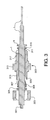
- Fig. 2 is a side view of another cylindrical ultrasonic probe according to an alternative embodiment of the invention.
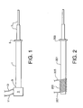
- FIG. 1 A first embodiment of an ultrasonic probe is shown in Fig. 1.
- the probe is an elongate body comprising four main parts: main probe body 1, ultrasonic transducer 3, enlarged support section or collar support section 5, and horn 7. All parts of the probe may be cylindrical or alternatively any portion of the probe may have a non-circular cross section. When any part of the probe has a non-circular cross section, the non-circular part may be characterized by an equivalent diameter defined as the diameter of a circular cross section having the same area as the non-circular cross section.
- equivalent diameter refers to the diameter of a circular cross section when the part is cylindrical and refers to the equivalent diameter when the part has a non-circular cross section, and therefore the term equivalent diameter includes both cylindrical and non-cylindrical parts.
- diameter and equivalent diameter have the same meaning and are interchangeable.
- Horn 7 operates as a booster to increase the amplitude of the ultrasonic waves generated by transducer 3 and transmitted by main probe body 1.
- the amplitude increases as the waves travel into progressively narrower sections of horn 7, and this focuses the ultrasonic energy for increased power density.
- the gain in ultrasonic wave amplitude provided by the decrease in cross-sectional area is typically equal to 0.8 times the ratio of the larger cross-sectional area to the smaller cross-sectional area.
- Ultrasonic transducer 3 which is shown schematically, may be a piezoelectric crystal or crystal assembly activated by alternating current supplied via conductors 11 and 13. These crystals oscillate at ultrasonic frequencies in the range of 20 KHz to 2 MHz and are commercially available in many different configurations.
- ultrasonic transducer 3 may be a magnetostrictive transducer assembly comprising iron or nickel surrounded by an electromagnetic coil attached to conductors 11 and 13 wherein the alternating magnetic field induces ultrasonic vibrations in the transducer.
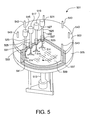
- Seal ring 319 is disposed between the threaded section 317 and collar support section 5.
- This torroidal seal ring may have a thin front section which fits into the annulus between the outer surface of probe body 1 and the inner surface of the bore in seal body 303.
- the seal ring may have a thicker rear section which fits between second end 311 and an inner surface of collar support section 5.
- the dimensions of collar support section 5 should be designed appropriately for the anticipated differential operating pressure across the seal (i.e., the pressure difference between the interior of the pressure vessel and atmospheric pressure) formed by seal ring 319, collar support section 5, and the face of second end 311 of seal body 303.
- the end of horn 7 may have a detachable tip of any shape.
- the detachable tip may have the same diameter as the end of horn 7.
- the detachable tip may have other geometries that are designed to direct or radiate ultrasonic energy in a particular manner for a given application.
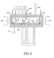
- the probe and seal assembly of Figs. 1 and 3 may be installed in a pressure vessel as illustrated in Fig. 4.
- probe 401 is inserted through seal body 403 attached to top 405 of pressure vessel body 407.
- Seal body 403 is shown here in phantom and represents the seal body 303 of Fig. 3.
- Ultrasonic transducer 409 is attached to the end of probe 401.
- Heaters 402 may be used to maintain the vessel at an elevated temperature.
- Pressure sensor 404 and temperature sensor 406 enable the monitoring of the pressure and temperature in the vessel.
- Fresh cleaning fluid 411 for example a supercritical fluid, flows into the vessel via inlet line 413. Contaminated cleaning fluid 415 exits the vessel via line 415.
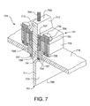
- Shoulder seal 741 has a thin upper section which fits into the gap between the lower portion of seal body 729 and planar surface portion 717 of main probe body 713.
- the shoulder seal has a thicker lower section which fits between shoulder support 709 and the bottom of seal body 729.
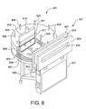
- FIG. 8 is an exemplary system designed for the cleaning of large-diameter flat articles such as silicon wafers using a flow of pressurized cleaning fluid.
- Pressure vessel 801 comprises vessel lid 803, cylindrical wall 805, and vessel bottom 807.
- Wafer 809 for example a 300 mm diameter wafer, is placed on a rotating table (not visible in this view) driven by shaft 813 via a magnetic coupling (not visible) installed on vessel bottom 807.
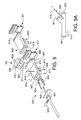
- the steps proceed as follows: (2) the loadlock/wafer loader gate valve 921 closes; (3) the pressure in the loadlock chamber 905 is equalized with that of the cleaning chamber 901 by opening a valve in a bypass line (not shown) around cleaning chamber/load lock gate valve 917; (4) the pressurized flow inlet is opened, allowing pressurized cleaning fluid to enter the cleaning chamber 901, and the load lock chamber pressurizes as cleaning fluid flows continuously through the cleaning chamber and passes to the chamber's outlet line; (5) cleaning chamber/loadlock gate valve 917 then opens; (6) carrier block 922 is then extended to a position under the wafer by actuating stepping motor 929; and (7) the wafer is lowered onto carrier block 922 using wafer lifting mechanism 923.
- step 8 stepping motor 929 is again actuated, but in the reverse direction, and carrier block 922 begins to move back into cleaning chamber 901 and carry the wafer into the cleaning chamber.
- step 9 ultrasonic transducer 933 is activated and ultrasonic energy begins to pass into the cleaning fluid, exposing the wafer to the cleaning process.
- the stepping motor then reverses direction in step 10, exposing the wafer to the second pass under the ultrasonically-activated probe.
- step 20 the cleaned wafer is unloaded.
- step 20 the wafer is lowered by lowering the lifting pins of wafer lifter 923.
- step 21 loadlock/wafer loader gate valve 921 is opened and the wafer is removed by the loader robot or operator. At this point the system has returned to its initial (step 1) status.
- a probe as described with reference to Fig. 3 was fabricated from titanium with the following dimensions: total length including main probe body 1, collar support section 5, and horn 7, 6.86 inch; combined length of probe body 1 and collar support section 5, 3.10 inch; total length of horn 7, 3.76 inch; length of larger diameter horn section, 1.76 inch; length of smaller diameter horn section, 2.00 inch; diameter of main probe body 1, 0.50 inch; diameter of smaller diameter horn section, 0.125 inch, and diameter of larger diameter horn section, 0.250 inch.
- the axial thickness of collar support section 5 is 0.125 inch and the diameter is 0.650 inch.
- the end of the horn adjacent collar support section 5 has a smooth radius transition from 0.500 inch diameter to 0.250 inch diameter and the smaller horn section adjacent the junction with larger horn section has a smooth radius transition from 0.250 inch diameter to 0.125 inch diameter.
- a planar probe as described with reference to Fig. 7 is fabricated from titanium with the following dimensions: total length of planar probe 701 having first end 703 and second end 705, 6.86 inch; combined length of upper, thicker portion of planar probe 701 and shoulder supports 707 and 709, 3.10 inch; total length of horn 711, 3.76 inch; thickness of main probe body 713, 0.50 inch; and thickness of horn 711, 0.125 inch.
- the axial thickness of shoulder supports 707 and 709 is 0.125 inch and the width of shoulder supports 707 and 709 perpendicular to the plane of planar probe 701 is 0.650 inch.
- the end of the horn adjacent shoulder supports 707 and 709 has a smooth radius transition from 0.250 inch diameter to 0.125 inch diameter.
Landscapes
- Engineering & Computer Science (AREA)
- Mechanical Engineering (AREA)
- General Engineering & Computer Science (AREA)
- Cleaning Or Drying Semiconductors (AREA)
- Cleaning By Liquid Or Steam (AREA)
- Apparatuses For Generation Of Mechanical Vibrations (AREA)
- Physical Or Chemical Processes And Apparatus (AREA)
- Investigating Or Analyzing Materials By The Use Of Ultrasonic Waves (AREA)
- Transducers For Ultrasonic Waves (AREA)
Abstract
Description
wherein the distance between the outer edge of the first longitudinal shoulder support section and the outer edge of the second longitudinal shoulder support section is greater than the thickness of the planar body at any location between the longitudinal shoulder supports and the first end, the thickness of the planar body being defined as the perpendicular distance between the first and second sides;
Claims (34)
- An ultrasonic probe comprising an elongate body having a first end and a second end, an ultrasonic transducer attached to the probe at or adjacent the first end, and an enlarged support section intermediate the ultrasonic transducer and the second end,
wherein the enlarged support section has an equivalent diameter greater than an equivalent diameter of the body at any location between the enlarged support section and the ultrasonic transducer. - The probe of Claim 1 wherein the ultrasonic transducer is a piezoelectric transducer or a magnetostrictive transducer.
- The probe of Claim 1 wherein the ultrasonic transducer is a magnetostrictive transducer formed by an electrical coil wrapped around a section of the probe between the first end and the enlarged support section.
- The probe of Claim 1 comprises a metal or metal alloy.
- The probe of Claim 1 wherein the probe has a circular cross section at any location between the first end and the second end, the cross section being defined as a section perpendicular to an axis defined by the first end and the second end.
- The probe of Claim 5 wherein at least a portion of the probe between the enlarged support section and the second end is cylindrical, and wherein the diameter of the probe decreases discontinuously in this portion.
- The probe of Claim 5 wherein the probe has a circular cross section at all locations between the enlarged support section and the second end, and wherein the diameter of the probe decreases continuously between the enlarged support section and the second end.
- The probe of Claim 1 wherein the ratio of the distance between the first end and the enlarged support section to the distance from the enlarged support section to the second end is between 1:10 and 10:1
- The probe of Claim 1 which further comprises a detachable tip attached to the second end of the probe.
- An ultrasonic probe comprising an elongate body having a first end and a second end, an ultrasonic transducer attached to the probe at or adjacent the first end, a cylindrical collar support section intermediate the ultrasonic transducer and the second end, wherein the probe is cylindrical between the first end and the collar support section, and wherein the collar support section has a diameter greater than diameter of the cylinder between the collar support section and the ultrasonic transducer.
- An ultrasonic probe comprisingwherein the distance between the outer edge of the first longitudinal shoulder support section and the outer edge of the second longitudinal shoulder support section is greater than the thickness of the planar body at any location between the longitudinal shoulder supports and the first end, the thickness of the planar body being defined as the perpendicular distance between the first and second sides.(a) an elongate planar body having a first end, a second end opposite the first end, a third end intersecting the first and second ends, a fourth end opposite the third end and intersecting the first and second ends, a first side intersecting the first, second, third, and fourth ends, and a second side opposite the first side and intersecting the first, second, third, and fourth ends;(b) attachment means on the first end adapted for attaching the first end to one or more transducer assemblies;(c) a first longitudinal shoulder support section projecting from the first side, extending linearly between the third and fourth ends, and having an outer edge; and(d) a second longitudinal shoulder support section projecting from the second side, extending linearly between the third and fourth ends, and having an outer edge, wherein the second longitudinal shoulder support section is disposed opposite the first longitudinal shoulder support section;
- An ultrasonic probe assembly comprising(a) a seal assembly comprising a seal body having a first end and a second end, an axis passing through the first end and the second end, and a coaxial cylindrical passage within the seal assembly between the first end and the second end;(b) An ultrasonic probe comprising an elongate body having a first end and a second end, an ultrasonic transducer attached to the probe at or adjacent the first end, and a cylindrical collar support section intermediate the ultrasonic transducer and the second end, wherein the probe is cylindrical between the ultrasonic transducer and the collar support section, the collar support section has a diameter greater than diameter of the cylinder between the collar support section and the ultrasonic transducer, the cylindrical section of the probe is disposed coaxially within the cylindrical passage of the seal body such that the shoulder support section is adjacent the second end of the seal body, and the diameter of the cylindrical shoulder section is greater than the diameter of the cylindrical passage at the second end of the seal body; and(c) an elastomeric torroidal seal ring disposed coaxially between the collar support section of the ultrasonic probe and the second end of the seal body.
- The ultrasonic probe assembly of Claim 12 wherein the cylindrical section of the ultrasonic probe extends beyond the first end of the seal body and wherein the ultrasonic probe assembly further comprises a compression fitting adapted to grip the ultrasonic probe and the first end of the seal body to maintain the ultrasonic probe in a coaxial position in the cylindrical passage of the seal assembly.
- The ultrasonic probe assembly of Claim 12 wherein the ultrasonic probe comprises a metal or metal alloy.
- The ultrasonic probe assembly of Claim 12 wherein the seal body comprises a metal or metal alloy.
- The ultrasonic probe assembly of Claim 12 wherein the elastomeric torroidal seal ring comprises an elastomer selected from the group consisting of tetrafluoroethylene, chlorotrifluoroethylene, polyvinylidene fluoride, perfluoroalkoxy, polyethylene, unplasticized polyvinyl chloride, acrylonitrile butadiene styrene, acetal, cellulose acetate butyrate, nylon, polypropylene, polycarbonate, polyphenylene oxide, polyphenylene sulfide, polysulfone, polyamide, polyimide, thermosetting plastic, natural rubber, hard rubber, chloroprene, neoprene, styrene rubber, nitrile rubber, butyl rubber, silicone rubber, chlorosulfonated polyethylene, polychlorotrifluoroethylene, polyvinyl chloride elastomer, cis-polybutadiene, cis-polyisoprene, ethylene-propylene rubbers, carbon, and graphite.
- The ultrasonic probe assembly of Claim 13 wherein the compression fitting includes a torroidal elastomeric ferrule comprising an elastomer selected from the group consisting of tetrafluoroethylene, chlorotrifluoroethylene, polyvinylidene fluoride, perfluoroalkoxy, polyethylene, unplasticized polyvinyl chloride, acrylonitrile butadiene styrene, acetal, cellulose acetate butyrate, nylon, polypropylene, polycarbonate, polyphenylene oxide, polyphenylene sulfide, polysulfone, polyamide, polyimide, thermosetting plastic, natural rubber, hard rubber, chloroprene, neoprene, styrene rubber, nitrile rubber, butyl rubber, silicone rubber, chlorosulfonated polyethylene, polychlorotrifluoroethylene, polyvinyl chloride elastomer, cis-polybutadiene, cis-polyisoprene, ethylene-propylene rubber, carbon, and graphite.
- The ultrasonic probe assembly of Claim 12 which further comprises a transducer assembly attached to the first end thereof.
- An ultrasonic processing system comprisingwherein the elastomeric torroidal seal ring is compressed between the collar support section and the second end of the seal body to form a seal between the interior and the exterior of the pressure vessel, and wherein the second end of the ultrasonic probe is disposed in the interior of the pressure vessel.(a) An ultrasonic probe assembly including(1) a seal assembly comprising a seal body having a first end and a second end, an axis passing through the first end and the second end, and a coaxial cylindrical passage disposed between the first end and the second end;(2) An ultrasonic probe comprising an elongate body having a first end and a second end, an ultrasonic transducer attached to the probe at or adjacent the first end, and a cylindrical collar support section intermediate the ultrasonic transducer and the second end, wherein the probe is cylindrical between the ultrasonic transducer and the collar support section, the collar support section has a diameter greater than diameter of the cylinder between the collar support section and the ultrasonic transducer, the cylindrical section of the probe is disposed coaxially within the cylindrical passage of the seal body such that the shoulder support section is adjacent the second end of the seal body, and the diameter of the cylindrical shoulder section is greater than the diameter of the cylindrical passage at the second end of the seal body; and(3) an elastomeric torroidal seal ring disposed coaxially between the collar support section of the ultrasonic probe and the second end of the seal body;(b) a pressure vessel having an interior, an exterior, and at least one opening between the interior and the exterior; and(c) first sealing means associated with the second end of the seal assembly and second sealing means associated with the at least one opening in the pressure vessel, wherein the first and second sealing means are adapted to form a seal between the seal assembly and the pressure vessel;
- The ultrasonic processing system of Claim 19 wherein the cylindrical section of the ultrasonic probe extends beyond the first end of the seal body and wherein the ultrasonic probe assembly further comprises a compression fitting adapted to grip the ultrasonic probe and the first end of the seal body to maintain the ultrasonic probe in a coaxial position in the cylindrical passage of the seal assembly.
- The ultrasonic processing system of Claim 19 wherein the ultrasonic probe assembly further comprises a transducer assembly attached to the first end thereof.
- The ultrasonic processing system of Claim 19 wherein the pressure vessel further comprises an inlet for introducing a fresh cleaning fluid into the pressure vessel and an outlet for withdrawing a contaminated cleaning fluid from the pressure vessel.
- The ultrasonic processing system of Claim 19 wherein the pressure vessel further comprises an inlet port for introducing one or more contaminated articles into the pressure vessel and an outlet port for withdrawing one or more cleaned articles from the pressure vessel.
- A method of providing ultrasonic energy to a pressurized fluid comprising(a) providing an ultrasonic pressure vessel system includingwherein the second end of the ultrasonic probe is disposed in the interior of the pressure vessel;(1) an ultrasonic probe assembly including(1a) a seal assembly comprising a seal body having a first end and a second end, an axis passing through the first end and the second end, and a coaxial cylindrical passage disposed between the first end and the second end;(1b) An ultrasonic probe comprising an elongate body having a first end and a second end, an ultrasonic transducer attached to the probe at or adjacent the first end, and a cylindrical collar support section intermediate the ultrasonic transducer and the second end,
wherein the probe is cylindrical between the ultrasonic transducer and the collar support section, the collar support section has a diameter greater than diameter of the cylinder between the collar support section and the ultrasonic transducer, the cylindrical section of the probe is disposed coaxially within the cylindrical passage of the seal body such that the shoulder support section is adjacent the second end of the seal body, and the diameter of the cylindrical shoulder section is greater than the diameter of the cylindrical passage at the second end of the seal body; and(1c) an elastomeric torroidal seal ring disposed coaxially between, and forming a seal between, the collar support section of the ultrasonic probe and the second end of the seal body;(2) a pressure vessel having an interior, an exterior, and at least first and second openings between the interior and the exterior; and(3) first sealing means associated with the second end of the seal assembly and second sealing means associated with the first opening in the pressure vessel, wherein the first and second sealing means are adapted to form a seal between the seal assembly and the pressure vessel, wherein the elastomeric torroidal seal ring is compressed between the collar support section and the second end of the seal body to form a seal between the interior and the exterior of the pressure vessel, and(b) introducing a pressurized fluid via the second opening into the interior of the pressure vessel;(c) providing electrical power to the ultrasonic transducer to generate ultrasonic energy; and(d) transmitting the ultrasonic energy through the ultrasonic probe to the pressurized fluid in the interior of the pressure vessel. - The method of Claim 24 wherein the pressure of the pressurized fluid in the interior of the pressure vessel is in the range of 10-3 to 680 atma.
- The method of Claim 24 wherein the ultrasonic energy is provided in a frequency range of 20 KHz to 2 MHz.
- The method of Claim 24 wherein the ultrasonic energy is provided at a power density in the range of 0.1 to 10,000 W/in2.
- The method of Claim 24 wherein the pressurized fluid comprises one or more components selected from the group consisting of carbon dioxide, nitrogen, methane, oxygen, ozone, argon, hydrogen, helium, ammonia, nitrous oxide, hydrogen fluoride, hydrogen chloride, sulfur trioxide, sulfur hexafluoride, nitrogen trifluoride, monofluoromethane, difluoromethane, tetrafluoromethane, trifluoromethane, trifluoroethane, tetrafluoroethane, pentafluoroethane, perfluoropropane, pentafluoropropane, hexafluoroethane, hexafluoropropylene, hexafluorobutadiene, octafluorocyclobutane, and tetrafluorochloroethane.
- The method of Claim 28 wherein the pressurized fluid further comprises one or more processing agents selected from a group consisting of an acetylenic alcohol, an acetylenic diol, a dialkyl ester, hydrogen fluoride, hydrogen chloride, chlorine trifluoride, nitrogen trifluoride, hexafluoropropylene, hexafluorobutadiene, octafluorocyclobutane tetrafluorochloroethane, fluoroxytrifluoromethane (CF4O), bis(difluoroxy)methane (CF4O2), cyanuric fluoride (C3F3N3), oxalyl fluoride (C2F2O2), nitrosyl fluoride (FNO), carbonyl fluoride (CF2O), perfluoromethylamine (CF5N), an ester, an ether, an alcohol, a nitrile, a hydrated nitrile, a glycol, a monester glycol, a ketone, a fluorinated ketone, a tertiary amine, an alkanolamine, an amide, a carbonate, a carboxylic acid, an alkane diol, an alkane, a peroxide, a water, an urea, a haloalkane, a haloalkene, a beta-diketone, a carboxylic acid, an oxine, a tertiary amine, a tertiary diamine, a tertiary triamine, a nitrile, a beta-ketoimine, an ethylenediamine tetraacetic acid and derivatives thereof, a catechol, a choline-containing compound, a trifluoroacetic anhydride, an oxime, a dithiocarbamate, and combinations thereof.
- The method of claim 28 which further comprises providing a sealable opening in the pressure vessel adapted to insert and withdraw one or more articles, inserting one or more contaminated articles into the pressure vessel prior to (b), cleaning the one or more contaminated articles during (c) and (d), depressurizing the pressure vessel by withdrawing a contaminated fluid therefrom, and withdrawing one or more cleaned articles therefrom.
- The method of Claim 24 wherein the fluid comprises at least one component which undergoes a chemical reaction that is promoted by the ultrasonic energy introduced into the pressure vessel.
- The method of Claim 24 wherein the shoulder support section of the ultrasonic probe is located at a vibrational node between the first and second ends of the ultrasonic probe.
- A method for cleaning a contaminated wafer comprising:(a) providing an ultrasonic pressure vessel system including(1) an ultrasonic probe assembly including(1 a) an elongate planar body having a first end, a second end opposite the first end, a third end intersecting the first and second ends, a fourth end opposite the third end and intersecting the first and second ends, a first side intersecting the first, second, third, and fourth ends, and a second side opposite the first side and intersecting the first, second, third, and fourth ends;(1b) attachment means on the first end adapted for attaching the first end to one or more transducer assemblies;(1c) a first longitudinal shoulder support section projecting from the first side, extending linearly between the third and fourth ends, and having an outer edge; and(1d) a second longitudinal shoulder support section projecting from the second side, extending linearly between the third and fourth ends, and having an outer edge, wherein the second longitudinal shoulder support section is disposed opposite the first longitudinal shoulder support section;
wherein the distance between the outer edge of the first longitudinal shoulder support section and the outer edge of the second longitudinal shoulder support section is greater than the thickness of the planar body at any location between the longitudinal shoulder supports and the first end, the thickness of the planar body being defined as the perpendicular distance between the first and second sides;(2) a reactor vessel having an interior, an exterior, and at least first and second openings between the interior and the exterior; and(3) first sealing means associated with the first and second longitudinal shoulder support sections and second sealing means associated with the first opening in the pressure vessel, wherein the first and second sealing means are adapted to form a seal between the ultrasonic probe and the pressure vessel, wherein the second end of the ultrasonic probe is disposed in the interior of the pressure vessel;(b) introducing the contaminated wafer into the interior of the pressure vessel;(c) introducing a pressurized fluid via the second opening into the interior of the pressure vessel, thereby pressurizing the vessel;(d) providing electrical power to the ultrasonic transducer to generate ultrasonic energy; and(e) transmitting the ultrasonic energy through the ultrasonic probe to the pressurized fluid in the interior of the pressure vessel while moving the wafer past the second end of the ultrasonic probe. - The method of Claim 33 wherein the wafer defines a first plane and the ultrasonic probe defines a second plane, and wherein the included angle between the first plane and the second plane is between 10 degrees and 90 degrees.
Applications Claiming Priority (2)
| Application Number | Priority Date | Filing Date | Title |
|---|---|---|---|
| US10/785,298 US7439654B2 (en) | 2004-02-24 | 2004-02-24 | Transmission of ultrasonic energy into pressurized fluids |
| US785298 | 2004-02-24 |
Publications (2)
| Publication Number | Publication Date |
|---|---|
| EP1570918A2 true EP1570918A2 (en) | 2005-09-07 |
| EP1570918A3 EP1570918A3 (en) | 2006-12-27 |
Family
ID=34750470
Family Applications (1)
| Application Number | Title | Priority Date | Filing Date |
|---|---|---|---|
| EP05003377A Withdrawn EP1570918A3 (en) | 2004-02-24 | 2005-02-17 | Transmission of ultrasonic energy into pressurized fluids |
Country Status (5)
| Country | Link |
|---|---|
| US (2) | US7439654B2 (en) |
| EP (1) | EP1570918A3 (en) |
| JP (1) | JP2005246376A (en) |
| KR (1) | KR20060043031A (en) |
| TW (1) | TWI246944B (en) |
Cited By (5)
| Publication number | Priority date | Publication date | Assignee | Title |
|---|---|---|---|---|
| WO2011023761A1 (en) | 2009-08-28 | 2011-03-03 | Lonza Ag | Method for preventing plugging of a continuous-reaction channel-system and micro-reactor for carrying out the method |
| CN110788062A (en) * | 2019-11-07 | 2020-02-14 | 无锡鼎桥新能源科技有限公司 | Graphite boat cleaning process |
| CN111229578A (en) * | 2020-03-11 | 2020-06-05 | 广西玉林浩杰新能源科技有限公司 | Double-end ultrasonic transducer capper |
| CN112317286A (en) * | 2020-09-07 | 2021-02-05 | 江苏大学 | Underwater sound wave radiator based on bionic principle |
| WO2025068795A3 (en) * | 2023-09-29 | 2025-05-15 | Precision Planting Llc | Ultrasonic cleaning of stir chamber for agricultural sample slurry |
Families Citing this family (28)
| Publication number | Priority date | Publication date | Assignee | Title |
|---|---|---|---|---|
| US7883534B1 (en) * | 2002-02-27 | 2011-02-08 | CAMS Medical Instruments, Inc. | Personal tuner |
| US9987185B1 (en) | 2002-02-27 | 2018-06-05 | CAMS Medical Instruments, Inc. | Transducer devices, apparatus, systems and methods of operation |
| US7086286B1 (en) * | 2005-06-09 | 2006-08-08 | General Electric Company | Transducer holder and nozzle |
| JP2010512998A (en) * | 2006-12-18 | 2010-04-30 | カビタス ピーティーワイ リミテッド | High energy ultrasonic extraction |
| US8210042B2 (en) * | 2007-02-22 | 2012-07-03 | Dow Global Technologies Llc | Use of acoustic signals for measuring membrane fouling in spiral wound modules |
| US20100171307A1 (en) * | 2009-01-05 | 2010-07-08 | Marlin Manufacturing Corporation | Fitting assembly with ferrule |
| ES2480422T3 (en) * | 2009-08-14 | 2014-07-28 | Ethicon Endo-Surgery, Inc. | Ultrasonic surgical apparatus |
| US9737735B2 (en) | 2009-08-14 | 2017-08-22 | Ethicon Llc | Ultrasonic surgical apparatus with silicon waveguide |
| EP2369020B1 (en) * | 2010-03-16 | 2016-10-05 | Thermission AG | Method for treating a metal element for an automobile |
| US9089886B2 (en) | 2011-09-23 | 2015-07-28 | Thermission Ag | Method of treating a metal element for an automobile |
| WO2013093183A1 (en) * | 2011-12-21 | 2013-06-27 | Vahterus Oy | Ultrasonic cleaner for a heat exchanger |
| JP5453487B2 (en) | 2012-05-24 | 2014-03-26 | ジルトロニック アクチエンゲゼルシャフト | Ultrasonic cleaning method and ultrasonic cleaning apparatus |
| EP2762842B1 (en) * | 2013-01-28 | 2024-02-14 | Krohne AG | Ultrasonic transducer for an ultrasonic flow rate meter |
| US9145597B2 (en) * | 2013-02-22 | 2015-09-29 | Almex Usa Inc. | Simultaneous multi-mode gas activation degassing device for casting ultraclean high-purity metals and alloys |
| US10478570B2 (en) | 2014-01-30 | 2019-11-19 | Dualams, Inc. | Medication delivery apparatus and accompanying system for the application of local anesthetics to a treatment site and method for use of same |
| US10018113B2 (en) * | 2015-11-11 | 2018-07-10 | General Electric Company | Ultrasonic cleaning system and method |
| US10087406B2 (en) * | 2016-05-17 | 2018-10-02 | Terressentia Corporation | Alcoholic beverage enhancing device |
| US20180147611A1 (en) * | 2016-11-29 | 2018-05-31 | 1863815 Ontario Limited | Apparatus, System and Method for Cleaning Inner Surfaces of Tubing |
| FR3064361B1 (en) * | 2017-03-24 | 2021-07-09 | Airbus Operations Sas | ULTRASONIC PROBE FOR BORING EQUIPPED WITH A COUPLING SUPPORT |
| FR3064362B1 (en) | 2017-03-24 | 2019-03-22 | Airbus Operations | ULTRASONIC PROBE FOR BORING EQUIPPED WITH AN EXCENTRATION DEVICE |
| KR102358561B1 (en) | 2017-06-08 | 2022-02-04 | 삼성전자주식회사 | Substrate processing apparatus and apparatus for manufacturing integrated circuit device |
| WO2019147592A1 (en) * | 2018-01-23 | 2019-08-01 | Tda Research, Inc. | Method for cleaning firearm suppressors |
| TWI671117B (en) * | 2018-11-02 | 2019-09-11 | 黃長義 | Ultrasonic extraction device |
| CN109570135A (en) * | 2018-11-28 | 2019-04-05 | 哈尔滨工业大学 | A kind of cleaning method of atomic force microscope silicon nitrate probes |
| US11400488B2 (en) * | 2019-02-27 | 2022-08-02 | Ametek, Inc. | High temperature ultrasonic transducers and signal connectors |
| CN110000147B (en) * | 2019-05-22 | 2023-12-22 | 杭州沃凌的机电有限公司 | Magnetostrictive ultrasonic cleaning valve |
| CN111649281B (en) * | 2020-06-19 | 2022-03-15 | 重庆安渝照明工程有限公司 | Self-cleaning street lamp and key mechanism thereof |
| KR102628488B1 (en) | 2020-09-25 | 2024-01-24 | 단국대학교 산학협력단 | Ultrasonic probe and method of manufacturing the same |
Family Cites Families (39)
| Publication number | Priority date | Publication date | Assignee | Title |
|---|---|---|---|---|
| US253054A (en) * | 1882-01-31 | Geoege w | ||
| US3131515A (en) * | 1960-01-04 | 1964-05-05 | Bell Telephone Labor Inc | Methods and apparatus employing torsionally vibratory energy |
| US3184842A (en) * | 1961-08-03 | 1965-05-25 | Aeroprojects Inc | Method and apparatus for delivering vibratory energy |
| US3381525A (en) * | 1965-05-21 | 1968-05-07 | Aeroprojects Inc | Method for detection of the imminence or incidence or cavitation in a liquid |
| US3433226A (en) | 1965-07-21 | 1969-03-18 | Aeroprojects Inc | Vibratory catheterization apparatus and method of using |
| US3475628A (en) * | 1966-12-28 | 1969-10-28 | Trustees Of The Ohio State Uni | Sonic transducer apparatus |
| US3546498A (en) * | 1969-06-13 | 1970-12-08 | Univ Ohio | Curved sonic transmission line |
| US3628071A (en) * | 1970-05-01 | 1971-12-14 | Branson Instr | Mechanical amplitude transformer |
| DE2613614C3 (en) | 1975-08-25 | 1979-05-17 | Siemens Ag, 1000 Berlin Und 8000 Muenchen | Ultrasonic transducer, suitable for liquid atomization |
| US4193009A (en) * | 1976-01-26 | 1980-03-11 | Durley Benton A Iii | Ultrasonic piezoelectric transducer using a rubber mounting |
| DE2606997A1 (en) | 1976-02-20 | 1977-08-25 | Mo I Khim Mash | Ultrasonic speed transformer with stepped concentrator - has rod of resonant length according to mode of longitudinal oscillation |
| DE2756134A1 (en) * | 1977-12-16 | 1979-06-21 | Ibm Deutschland | PIEZOELECTRICALLY CONTROLLED DRIVE ARRANGEMENT FOR THE GENERATION OF HIGH SHOCK SPEEDS AND / OR CONTROLLED STROKE |
| US4425115A (en) | 1977-12-19 | 1984-01-10 | Wuchinich David G | Ultrasonic resonant vibrator |
| GB2029270B (en) | 1978-07-11 | 1982-11-03 | Plessey Co Ltd | Vibratory atomiser |
| DE3027533C2 (en) | 1980-07-21 | 1986-05-15 | Telsonic Aktiengesellschaft für elektronische Entwicklung und Fabrikation, Bronschhofen | Process for generating and emitting ultrasonic energy in liquids and an ultrasonic resonator for carrying out the process |
| GB2116046B (en) * | 1982-03-04 | 1985-05-22 | Wolf Gmbh Richard | Apparatus for disintegrating and removing calculi |
| US4583101A (en) * | 1982-12-27 | 1986-04-15 | Eastman Kodak Company | Fluid jet print head and stimulator therefor |
| US5013366A (en) | 1988-12-07 | 1991-05-07 | Hughes Aircraft Company | Cleaning process using phase shifting of dense phase gases |
| JPH03234450A (en) | 1990-02-06 | 1991-10-18 | Brother Ind Ltd | ultrasonic processing machine |
| EP0619751B1 (en) | 1992-10-16 | 2003-05-07 | Suprex Corporation | Automated supercritical fluid extraction |
| US5337446A (en) | 1992-10-27 | 1994-08-16 | Autoclave Engineers, Inc. | Apparatus for applying ultrasonic energy in precision cleaning |
| US5377705A (en) | 1993-09-16 | 1995-01-03 | Autoclave Engineers, Inc. | Precision cleaning system |
| US5522938A (en) | 1994-08-08 | 1996-06-04 | Texas Instruments Incorporated | Particle removal in supercritical liquids using single frequency acoustic waves |
| JP2875211B2 (en) | 1996-06-28 | 1999-03-31 | 株式会社アルテクス | Ultrasonic horn for soldering |
| US6039059A (en) | 1996-09-30 | 2000-03-21 | Verteq, Inc. | Wafer cleaning system |
| US6617760B1 (en) * | 1999-03-05 | 2003-09-09 | Cybersonics, Inc. | Ultrasonic resonator |
| US6228563B1 (en) | 1999-09-17 | 2001-05-08 | Gasonics International Corporation | Method and apparatus for removing post-etch residues and other adherent matrices |
| US6204592B1 (en) * | 1999-10-12 | 2001-03-20 | Ben Hur | Ultrasonic nailing and drilling apparatus |
| US6286231B1 (en) | 2000-01-12 | 2001-09-11 | Semitool, Inc. | Method and apparatus for high-pressure wafer processing and drying |
| KR100467985B1 (en) | 2000-12-14 | 2005-01-24 | 한국전력공사 | Ultrasonic Temperature Sensor to Measure Very High Temperature in Ultra-High Temperature |
| US20030116176A1 (en) | 2001-04-18 | 2003-06-26 | Rothman Laura B. | Supercritical fluid processes with megasonics |
| JP2003031547A (en) | 2001-07-11 | 2003-01-31 | Nippon Telegr & Teleph Corp <Ntt> | Supercritical drying method and apparatus |
| IL144638A (en) * | 2001-07-30 | 2005-12-18 | Nano Size Ltd | High power ultrasound reactor for the production of nano-powder materials |
| JP2004050796A (en) | 2002-07-24 | 2004-02-19 | Nec Tokin Corp | Ultrasonic engraving pen |
| US20040055621A1 (en) * | 2002-09-24 | 2004-03-25 | Air Products And Chemicals, Inc. | Processing of semiconductor components with dense processing fluids and ultrasonic energy |
| US6880560B2 (en) | 2002-11-18 | 2005-04-19 | Techsonic | Substrate processing apparatus for processing substrates using dense phase gas and sonic waves |
| US6652992B1 (en) * | 2002-12-20 | 2003-11-25 | Sulphco, Inc. | Corrosion resistant ultrasonic horn |
| US6984921B1 (en) * | 2003-02-21 | 2006-01-10 | Dukane Corporation | Apparatus and method for resonant mounting of vibration structure |
| US7156189B1 (en) * | 2004-12-01 | 2007-01-02 | The United States Of America As Represented By The Administrator Of The National Aeronautics And Space Administration | Self mountable and extractable ultrasonic/sonic anchor |
-
2004
- 2004-02-24 US US10/785,298 patent/US7439654B2/en not_active Expired - Fee Related
-
2005
- 2005-02-17 EP EP05003377A patent/EP1570918A3/en not_active Withdrawn
- 2005-02-21 KR KR1020050014154A patent/KR20060043031A/en not_active Ceased
- 2005-02-21 TW TW094105085A patent/TWI246944B/en not_active IP Right Cessation
- 2005-02-24 JP JP2005049142A patent/JP2005246376A/en not_active Withdrawn
-
2008
- 2008-04-28 US US12/110,831 patent/US20080202550A1/en not_active Abandoned
Cited By (6)
| Publication number | Priority date | Publication date | Assignee | Title |
|---|---|---|---|---|
| WO2011023761A1 (en) | 2009-08-28 | 2011-03-03 | Lonza Ag | Method for preventing plugging of a continuous-reaction channel-system and micro-reactor for carrying out the method |
| CN110788062A (en) * | 2019-11-07 | 2020-02-14 | 无锡鼎桥新能源科技有限公司 | Graphite boat cleaning process |
| CN111229578A (en) * | 2020-03-11 | 2020-06-05 | 广西玉林浩杰新能源科技有限公司 | Double-end ultrasonic transducer capper |
| CN112317286A (en) * | 2020-09-07 | 2021-02-05 | 江苏大学 | Underwater sound wave radiator based on bionic principle |
| CN112317286B (en) * | 2020-09-07 | 2022-06-21 | 江苏大学 | An underwater acoustic radiator based on bionic principle |
| WO2025068795A3 (en) * | 2023-09-29 | 2025-05-15 | Precision Planting Llc | Ultrasonic cleaning of stir chamber for agricultural sample slurry |
Also Published As
| Publication number | Publication date |
|---|---|
| JP2005246376A (en) | 2005-09-15 |
| EP1570918A3 (en) | 2006-12-27 |
| TW200528203A (en) | 2005-09-01 |
| US20050183739A1 (en) | 2005-08-25 |
| TWI246944B (en) | 2006-01-11 |
| US7439654B2 (en) | 2008-10-21 |
| US20080202550A1 (en) | 2008-08-28 |
| KR20060043031A (en) | 2006-05-15 |
Similar Documents
| Publication | Publication Date | Title |
|---|---|---|
| US7439654B2 (en) | Transmission of ultrasonic energy into pressurized fluids | |
| EP0938745B1 (en) | Wafer cleaning system | |
| EP2969271B1 (en) | Ultrasonically cleaning vessels and pipes | |
| US7033068B2 (en) | Substrate processing apparatus for processing substrates using dense phase gas and sonic waves | |
| US20030232512A1 (en) | Substrate processing apparatus and related systems and methods | |
| US6578659B2 (en) | Ultrasonic horn assembly | |
| US20180147611A1 (en) | Apparatus, System and Method for Cleaning Inner Surfaces of Tubing | |
| JP2005169278A (en) | Ultrasonic cleaning nozzle and ultrasonic cleaning device | |
| KR20050019129A (en) | Substrate processing apparatus and related systems and methods | |
| US12072318B2 (en) | Chamber component cleanliness measurement system | |
| JP2856998B2 (en) | Ultrasonic cleaning equipment | |
| KR100567966B1 (en) | Cylindrical ultrasonic cleaning device | |
| CA2393607A1 (en) | Ultrasonic horn assembly | |
| RU191570U1 (en) | Small Vacuum Sealant | |
| KR101440418B1 (en) | Anti-Powder system for preventing powder deposition in pipe | |
| JP2026059674A (en) | Ultrasonic vibration device, ultrasonic cleaning device, cleaning method, and method for manufacturing a semiconductor device | |
| EP3957409A2 (en) | Industrial system | |
| WO2025070708A1 (en) | Ultrasonic vibration device, ultrasonic cleaning device, cleaning method, and method for manufacturing semiconductor device | |
| KR20250136458A (en) | A system using jet flow from bubbles excited by acoustic wave for cleaning contaminants and a method for manufacturing such a device | |
| WO2020022926A1 (en) | Ultrasonic method of unloading a solid bulk material |
Legal Events
| Date | Code | Title | Description |
|---|---|---|---|
| PUAI | Public reference made under article 153(3) epc to a published international application that has entered the european phase |
Free format text: ORIGINAL CODE: 0009012 |
|
| AK | Designated contracting states |
Kind code of ref document: A2 Designated state(s): AT BE BG CH CY CZ DE DK EE ES FI FR GB GR HU IE IS IT LI LT LU MC NL PL PT RO SE SI SK TR |
|
| AX | Request for extension of the european patent |
Extension state: AL BA HR LV MK YU |
|
| PUAL | Search report despatched |
Free format text: ORIGINAL CODE: 0009013 |
|
| AK | Designated contracting states |
Kind code of ref document: A3 Designated state(s): AT BE BG CH CY CZ DE DK EE ES FI FR GB GR HU IE IS IT LI LT LU MC NL PL PT RO SE SI SK TR |
|
| AX | Request for extension of the european patent |
Extension state: AL BA HR LV MK YU |
|
| AKX | Designation fees paid | ||
| STAA | Information on the status of an ep patent application or granted ep patent |
Free format text: STATUS: THE APPLICATION IS DEEMED TO BE WITHDRAWN |
|
| 18D | Application deemed to be withdrawn |
Effective date: 20070628 |
|
| REG | Reference to a national code |
Ref country code: DE Ref legal event code: 8566 |