EP2762842B1 - Ultrasonic transducer for an ultrasonic flow rate meter - Google Patents
Ultrasonic transducer for an ultrasonic flow rate meter Download PDFInfo
- Publication number
- EP2762842B1 EP2762842B1 EP14000845.9A EP14000845A EP2762842B1 EP 2762842 B1 EP2762842 B1 EP 2762842B1 EP 14000845 A EP14000845 A EP 14000845A EP 2762842 B1 EP2762842 B1 EP 2762842B1
- Authority
- EP
- European Patent Office
- Prior art keywords
- housing
- transducer
- ultrasonic
- coupling system
- window
- Prior art date
- Legal status (The legal status is an assumption and is not a legal conclusion. Google has not performed a legal analysis and makes no representation as to the accuracy of the status listed.)
- Active
Links
- 230000008878 coupling Effects 0.000 claims description 83
- 238000010168 coupling process Methods 0.000 claims description 83
- 238000005859 coupling reaction Methods 0.000 claims description 83
- 238000002604 ultrasonography Methods 0.000 claims description 32
- 238000013016 damping Methods 0.000 claims description 21
- 239000000463 material Substances 0.000 claims description 16
- 230000007704 transition Effects 0.000 claims description 4
- 229910000906 Bronze Inorganic materials 0.000 claims description 3
- RYGMFSIKBFXOCR-UHFFFAOYSA-N Copper Chemical compound [Cu] RYGMFSIKBFXOCR-UHFFFAOYSA-N 0.000 claims description 3
- 239000010974 bronze Substances 0.000 claims description 3
- KUNSUQLRTQLHQQ-UHFFFAOYSA-N copper tin Chemical compound [Cu].[Sn] KUNSUQLRTQLHQQ-UHFFFAOYSA-N 0.000 claims description 3
- 239000008187 granular material Substances 0.000 claims description 3
- 230000001681 protective effect Effects 0.000 claims description 3
- 230000035515 penetration Effects 0.000 claims 1
- 238000005516 engineering process Methods 0.000 description 8
- 238000005259 measurement Methods 0.000 description 8
- 230000005540 biological transmission Effects 0.000 description 7
- 230000005236 sound signal Effects 0.000 description 6
- 230000000694 effects Effects 0.000 description 5
- 230000010355 oscillation Effects 0.000 description 2
- 230000015572 biosynthetic process Effects 0.000 description 1
- 230000001419 dependent effect Effects 0.000 description 1
- 230000003993 interaction Effects 0.000 description 1
- 230000000149 penetrating effect Effects 0.000 description 1
- 238000003466 welding Methods 0.000 description 1
Images

Classifications
-
- G—PHYSICS
- G10—MUSICAL INSTRUMENTS; ACOUSTICS
- G10K—SOUND-PRODUCING DEVICES; METHODS OR DEVICES FOR PROTECTING AGAINST, OR FOR DAMPING, NOISE OR OTHER ACOUSTIC WAVES IN GENERAL; ACOUSTICS NOT OTHERWISE PROVIDED FOR
- G10K11/00—Methods or devices for transmitting, conducting or directing sound in general; Methods or devices for protecting against, or for damping, noise or other acoustic waves in general
- G10K11/004—Mounting transducers, e.g. provided with mechanical moving or orienting device
-
- G—PHYSICS
- G01—MEASURING; TESTING
- G01F—MEASURING VOLUME, VOLUME FLOW, MASS FLOW OR LIQUID LEVEL; METERING BY VOLUME
- G01F1/00—Measuring the volume flow or mass flow of fluid or fluent solid material wherein the fluid passes through a meter in a continuous flow
- G01F1/66—Measuring the volume flow or mass flow of fluid or fluent solid material wherein the fluid passes through a meter in a continuous flow by measuring frequency, phase shift or propagation time of electromagnetic or other waves, e.g. using ultrasonic flowmeters
- G01F1/662—Constructional details
-
- G—PHYSICS
- G01—MEASURING; TESTING
- G01F—MEASURING VOLUME, VOLUME FLOW, MASS FLOW OR LIQUID LEVEL; METERING BY VOLUME
- G01F15/00—Details of, or accessories for, apparatus of groups G01F1/00 - G01F13/00 insofar as such details or appliances are not adapted to particular types of such apparatus
- G01F15/18—Supports or connecting means for meters
-
- G—PHYSICS
- G10—MUSICAL INSTRUMENTS; ACOUSTICS
- G10K—SOUND-PRODUCING DEVICES; METHODS OR DEVICES FOR PROTECTING AGAINST, OR FOR DAMPING, NOISE OR OTHER ACOUSTIC WAVES IN GENERAL; ACOUSTICS NOT OTHERWISE PROVIDED FOR
- G10K11/00—Methods or devices for transmitting, conducting or directing sound in general; Methods or devices for protecting against, or for damping, noise or other acoustic waves in general
- G10K11/002—Devices for damping, suppressing, obstructing or conducting sound in acoustic devices
Definitions
- the invention relates to an ultrasonic transducer as an essential part of an ultrasonic flow measuring device, with a transducer housing and a transducer element, the transducer housing having an ultrasonic window and a housing tube, the transducer element designed for sending or receiving ultrasonic waves and either close to the ultrasonic window of the transducer housing or far from the ultrasonic window of the Transducer housing is provided, wherein a relatively soft mechanical coupling system is provided, which has at least one weakly coupled mechanical resonator or at least two weakly coupled resonators, and wherein a second soft mechanical coupling system is provided.
- the transducer housing can have the ultrasound window in a first area.
- the ultrasonic waves can be transmitted as housing waves between the first region of the transducer housing via a mediating wide region of the transducer housing into a third region of the transducer housing opposite the first region of the first transducer housing.
- the relatively soft mechanical coupling system can be provided in the second area of the converter housing.
- measurement, control, regulation and automation technology is particularly important. This applies in particular to measurement technology, which is the basis of control, regulation and automation technology.
- An important area of measurement technology is flow measurement technology (see the comprehensive presentation of Prof. Dr. sc. nat. Otto Fiedler "Flow and flow measurement technology, R. Oldenbourg Verlag Kunststoff 101992 ).
- flow measurement technology is flow measurement based on mechanical operating principles, in particular variable area flowmeters and Coriolis flowmeters, thermal flowmeters, magnetic-inductive flowmeters and ultrasonic flowmeters.
- Ultrasonic flowmeters exploit the effect that in a medium transported in a measuring tube, the speed of propagation of the sound signal is superimposed on the transport speed of the medium is.
- the measured propagation speed of the sound signal relative to the measuring tube is therefore greater than in the stationary medium when the medium is transported in the direction of the sound signal, and the speed of the sound signal relative to the measuring tube is lower than in the stationary medium when the medium is transported in the opposite direction to the sound signal becomes. Due to the entrainment effect, the transit time of the sound signal between the sound transmitter and the sound receiver - the sound transmitter and the sound receiver are ultrasonic transducers - depends on the transport speed of the medium relative to the measuring tube and thus relative to the ultrasonic transducer, i.e. relative to the sound transmitter and the sound receiver.
- the problem with ultrasonic flowmeters is that the ultrasonic waves generated in the ultrasonic transducer or the ultrasonic waves received by the ultrasonic transducer are not only transmitted from the transmitting and/or receiving side of the transducer housing into the surrounding medium of the ultrasonic transducer, but that the ultrasonic waves - sent or received - are also transmitted via the converter housing, if necessary also via a housing holder.
- This is not only problematic because a significant portion of the transmission power or reception power may be "lost", but rather it is particularly problematic because the ultrasonic waves transmitted to the transducer housing through so-called crosstalk also cause significant interference on the receiving side being able to lead. The reason for this is that on the receiving side, for example, it is not possible to distinguish whether the received ultrasonic waves were received via the medium - useful signal - or via the transducer housing.
- the proportion of oscillation energy transmitted by the ultrasonic transducer into the gaseous medium is very small compared to the total oscillation energy generated, so that the problem of crosstalk is particularly serious here.
- Some measures address the task of preventing such housing waves from developing. These include, for example, certain configurations of the ultrasonic window of the transducer housing with regard to particularly good impedance matching to maximize the transmitted energy component or with regard to a design of the ultrasonic window as a ⁇ /4 layer to reduce reflections. Other measures deal with preventing housing waves that have already arisen from being passed on, for example through mismatched acoustic impedance transitions.
- an ultrasonic transducer is known as part of an ultrasonic flow measuring device, which has two mechanical resonators that are designed in different ways.
- the US 5,159,838 discloses an ultrasonic transducer as part of an ultrasonic flowmeter.
- a measuring tube is connected to a flange via a first damping system and a second damping system.
- the first damping system is implemented as a vacuum bag, the second damping system is filled with a damping material.
- the sound waves are weakened by the damping systems.
- the WO 00/72000 A1 discloses an ultrasonic transducer with a mounting section and with a transducer section.
- a mechanical coupling system is arranged between the fastening section and the transducer section of the ultrasonic transducer.
- the ultrasound transducer described at the beginning, on which the invention is based, belongs to the German disclosure document 10 2008 033 098 and through the same content European publication 2 148 322 to the state of the art.
- a further measure to prevent the transmission of housing waves to the transducer housing of the ultrasonic transducer is implemented in that a relatively soft mechanical coupling system is provided in the second region of the transducer housing and the coupling system has at least two weakly coupled, essentially one behind the other in the direction of propagation of the housing waves has mechanical resonators.
- the mechanical resonators initially make it possible to “catch” the energy transported by the ultrasonic waves locally, namely by exciting the mechanical resonators to oscillate.
- Mechanical resonators can usually be described as spring-mass systems, although in real spring-mass systems the property of the spring - namely a deflection-dependent force effect - cannot be realized without making a contribution - albeit a very small one - to the mass of the resonator, in the same way how a mass always influences the spring properties of the spring-mass system due to its constructive introduction into the resonator; Spring and mass cannot be completely separated from each other in terms of design.
- the serial arrangement of the at least two mechanical resonators in the direction of propagation of the housing shafts ensures that the housing shafts have to pass through all the resonators in order to get from the first area of the converter housing to the third area of the converter housing and vice versa.
- the weak coupling of the two resonators means that the resonators overall represent a greater obstacle to the housing shafts than is the case with strongly coupled resonators, even if they otherwise have the same vibration properties. With a strong mechanical coupling, the vibration of one resonator is transmitted almost immediately to the neighboring resonator, which is not the case with a weak mechanical coupling, although here too there is of course a mechanical interaction between the neighboring resonators.
- the previously described coupling system consisting of at least two weakly coupled mechanical resonators is also referred to as a “relatively soft mechanical coupling system”, and with regard to possible implementations, in order to avoid repetition, reference is made to the disclosure content of German published publication 10 2008 033 098 or the parallel one European publication 2 148 322 referred; The disclosure content of these pre-published publications is hereby expressly made the disclosure content in connection with the present invention.
- the object underlying the invention is to improve the ultrasonic transducer on which the invention is based with regard to preventing the transmission of housing waves.
- an ultrasonic transducer that is improved with regard to preventing the transmission of housing waves has a second soft mechanical coupling system, which is implemented essentially in accordance with the first coupling system.
- the transducer housing has a housing flange, that of the two coupling systems, one coupling system is arranged on the side of the housing flange close to the ultrasound window and the other coupling system is arranged on the side of the housing flange remote from the ultrasound window, that is on the side of the housing flange close to the ultrasound window
- the coupling system provided on the housing flange is connected to the housing tube at its end near the ultrasonic window and to the housing flange at its end remote from the ultrasonic window and that the coupling system provided on the side of the housing flange remote from the ultrasonic window is connected to the housing tube at its end remote from the ultrasonic window and at its end Ultrasonic window near end is connected to the housing flange, so that the two coupling systems are anti-parallel effective.
- the teaching goes this way when a second coupling system is provided to realize the design and arrangement of the two coupling systems so that they are effective in anti-parallel.
- the transducer element is provided at the lower end of the transducer housing, that is to say at the end that faces the flowing medium or into the flowing medium Medium protrudes.
- the mechanical coupling system is more or less implemented at the upper end of the converter housing, in a certain sense also part of the converter housing.
- the area of the converter housing in which the converter element is provided has been referred to above as the first area of the converter housing, the upper area as the third area and the area lying between the first area and the third area as the second area, namely as the mediating second area of the converter housing, over which the housing waves spread in the direction of the third area of the converter housing.
- the well-known ultrasonic transducer on which the invention is based can also be described as being designed in three parts, namely a lower first area that accommodates the transducer element, a mediating second area and an upper third area to which the coupling system belongs.
- the lower first area, the intermediate second area and the upper third area are each connected to one another by welding.
- the mediating second area can be a housing tube; the upper end of the converter housing can be designed as a housing flange.
- the lower first area of the converter housing, the mediating second area of the converter housing designed as a housing tube, the coupling system and the housing flange are arranged in series.
- the ultrasonic transducer according to the invention is then characterized in that of the two coupling systems, one coupling system is arranged on the side of the housing flange close to the transducer element and the other coupling system is arranged on the side of the housing flange remote from the transducer element.
- Housing waves emanating from the converter element in the coupling system close to the converter element on the one hand and in the coupling system remote from the converter element on the other hand have a partially, preferably completely compensating effect with respect to the housing flange.
- the coupling systems are preferably connected to the housing tube and the housing flange.
- This connection can of course be realized in different ways.
- the end of the coupling system close to the converter element and the end of the coupling system remote from the converter element are welded to the housing tube.
- an embodiment is recommended in which the end of the coupling system close to the converter element and the end of the coupling system remote from the converter element close to the converter element are designed in one piece with the housing flange.
- the transducer element is located on or in the end of the transducer housing facing the medium.
- the transducer elements are often piezo elements that cannot be used above a certain temperature, the Curie temperature.
- the transducer elements are provided at the end remote from the medium, and the ultrasound generated is fed to the ultrasound window via a sound funnel and a funnel jacket (cf. the German patent specification 198 12 458 and the same content European patent specification 1 046 886 ).
- the coupling system or systems with an externally circumferential groove or grooves, i.e.
- an ultrasonic transducer according to the invention is characterized in that damping material is provided within the transducer housing, in particular bronze granules or bronze powder. So that this damping material cannot penetrate into the ultrasound window, which of course must remain free, it is further provided that the transducer housing has a separating disk at its end near the ultrasound window which prevents the damping material from penetrating into the ultrasound window.
- the damping material provided within the transducer housing in the last described embodiment of an ultrasonic transducer according to the invention only works particularly well if it is under a certain pressure within the transducer housing. Consequently, it is recommended to provide a pressure generating device which acts on the damping material at the end of the transducer housing remote from the ultrasound window.
- This pressure generating device preferably has a spring supported on one side on the converter housing and acting on the damping material on the other side, in particular a plate spring package.
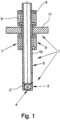
- the ultrasonic transducers shown in the figures are each an essential part of an ultrasonic flow measuring device, which is otherwise not shown, and initially have a transducer housing 1 and a transducer element 2, which is preferably a piezo element.
- the transducer element 2 is designed to transmit or receive ultrasonic waves.
- the transducer housing 1 has an ultrasound window 4 in a first area 3.
- the transducer element 2 is provided near the ultrasound window 4 of the transducer housing 1.
- the converter element 2 outside the converter housing 1.
- the ultrasonic transducers according to the invention are further improved in terms of preventing the transmission of housing waves.
- a second soft mechanical coupling system 9 is provided - in addition to the coupling system 7.
- This second coupling system 9 is essentially implemented in accordance with the first coupling system 7.
- the mechanical resonators 8 essentially work one behind the other in the direction of propagation of the housing waves, so the resonators work in series.
- the transducer element 2 is provided at the lower end of the transducer housing 1, that is to say at the end that faces the flowing medium or also protrudes into the flowing medium.
- the first mechanical coupling system 7 is realized at the upper end of the transducer housing 1, as it were part of the transducer housing 1.
- the known ultrasonic transducer and the ultrasonic transducer according to the invention can also be described insofar as it has been described so far in that it is designed in three parts, namely one lower first, the transducer element 2 receiving area 3, a mediating second area 5 and an upper third area 6, to which the first coupling system 7 belongs.
- the mediating second area 5 can specifically be a housing tube 10, the upper end of the converter housing 1 can be designed as a housing flange 11.
- the lower first area 3 of the converter housing 1, the mediating second area 5 of the converter housing 1, designed as a housing tube 10, the first coupling system 7 and the housing flange 11 are therefore arranged in series.
- the ultrasonic transducers are characterized in that of the two coupling systems 7, 9, the first coupling system 7 is on the side of the housing flange 11 close to the transducer element 2 and the second coupling system 9 is on the side of the housing flange 11 remote from the transducer element 2 is arranged.
- this is implemented in detail in such a way that the first coupling system 7 provided on the side of the housing flange 11 close to the converter element 2 is connected to the housing tube 2 at its end close to the converter element 2 and to the housing flange 11 at its end remote from the converter element 2 is connected, and that the second coupling system provided on the side of the housing flange 11 remote from the converter element 2 is connected to the housing tube 10 at its end remote from the converter element 2 and to the housing flange 11 at its end close to the converter element 2.
- the two coupling systems 7, 9 are therefore effective in an anti-parallel manner.
- connection of the coupling systems 7, 9 to the housing tube 10 and the housing flange 11 can be implemented in different ways.
- the end of the first coupling system 7 close to the converter element 2 and the end of the second coupling system 9 remote from the converter element 2 are welded to the housing tube 10.
- the end of the first coupling system 7 close to the converter element 2 and the end of the second coupling system 9 remote from the converter element 2 close to the converter element 2 are designed in one piece with the housing flange 11.
- the transducer element 2 is located at the end of the transducer housing 1 facing the medium whose flow rate is to be determined.
- the transducer elements in ultrasonic transducers are often piezo elements that cannot be used above a certain temperature, the Curie temperature. Consequently, there are also ultrasonic transducers in the prior art in which the transducer elements are provided at the end remote from the medium (cf German patent specification 198 12 458 and the same content European patent specification 1 046 886 ).
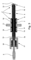
- the Fig. 2 and 3 show exemplary embodiments of ultrasonic transducers in which the transducer elements 2 are provided at the far end of the medium whose flow rate is to be measured.
- Fig. 2 and 3 in this respect preferred embodiments of ultrasonic transducers, as the coupling systems 7 and 9 are each provided with an externally circumferential groove 12, so an elastic hinge is realized, as it were, between a mechanical resonator 8 and the other mechanical resonator 8.
- the grooves 12 are designed in the shape of a circular arc in the base of the groove or are provided with transitions in the shape of a circular arc to the groove flanks, thereby avoiding mechanical overstress.
- the Fig. 3 shows a particularly preferred embodiment of an ultrasonic transducer.
- the transducer element 2 is provided at the end remote from the ultrasound window 4 of the transducer housing 1.
- An ultrasonic waveguide 15 is provided between the transducer element 2 and the ultrasound window 4 and is surrounded by a protective tube 16.
- the damping material 13 provided within the transducer housing 1 is only intended to dampen housing waves and, of course, not to negatively influence the transmission properties of the ultrasonic waveguide.
- Damping material 13 provided within the converter housing preferably bronze granules or bronze powder, works particularly well if or only if it is under a certain pressure inside the converter housing 1.
- pressure generating device 17 acting on the damping material 13 is provided, which in the exemplary embodiment is supported on one side on the converter housing 1 and on the other side has a spring 18 acting on the damping material 13, in the exemplary embodiment shown a plate spring package.
Description
Die Erfindung betrifft einen Ultraschallwandler als ein wesentlicher Teil eines Ultraschalldurchflussmessgeräts, mit einem Wandlergehäuse und einem Wandlerelement, wobei das Wandlergehäuse ein Ultraschallfenster und ein Gehäuserohr aufweist, das Wandlerelement zum Senden oder Empfangen von Ultraschallwellen ausgebildet und entweder nahe dem Ultraschallfenster des Wandlergehäuses oder fern vom Ultraschallfenster des Wandlergehäuses vorgesehen ist, wobei ein relativ weiches mechanisches Koppelsystem vorgesehen ist, das wenigstens einen schwach gekoppelten mechanischen Resonator oder wenigstens zwei schwach gekoppelte Resonatoren aufweist, und wobei ein zweites weiches mechanisches Koppelsystem vorgesehen ist. Dabei kann das Wandlergehäuse in einem ersten Bereich das Ultraschallfenster aufweisen. Üblicherweise sind die Ultraschallwellen als Gehäusewellen zwischen dem ersten Bereich des Wandlergehäuses über einen vermittelnden weiten Bereich des Wandlergehäuses in einen dem ersten Bereich des ersten Wandlergehäuses gegenüberliegenden dritten Bereich des Wandlergehäuses übertragbar. Das relativ weiche mechanische Koppelsystem kann im zweiten Bereich des Wandlergehäuses vorgesehen sein..The invention relates to an ultrasonic transducer as an essential part of an ultrasonic flow measuring device, with a transducer housing and a transducer element, the transducer housing having an ultrasonic window and a housing tube, the transducer element designed for sending or receiving ultrasonic waves and either close to the ultrasonic window of the transducer housing or far from the ultrasonic window of the Transducer housing is provided, wherein a relatively soft mechanical coupling system is provided, which has at least one weakly coupled mechanical resonator or at least two weakly coupled resonators, and wherein a second soft mechanical coupling system is provided. The transducer housing can have the ultrasound window in a first area. Typically, the ultrasonic waves can be transmitted as housing waves between the first region of the transducer housing via a mediating wide region of the transducer housing into a third region of the transducer housing opposite the first region of the first transducer housing. The relatively soft mechanical coupling system can be provided in the second area of the converter housing.
In der Industrie kommt der Mess-, Steuer-, Regel- und Automatisierungstechnik besondere Bedeutung zu. Das gilt insbesondere für die Messtechnik, die Grundlage der Steuer-, Regel- und Automatisierungstechnik ist. Ein bedeutender Bereich der Messtechnik ist die Durchflussmesstechnik (vgl. die umfassende Darstellung von
Bei Ultraschalldurchflussmessgeräten wird der Effekt ausgenutzt, dass in einem in einem Messrohr transportierten Medium der Ausbreitungsgeschwindigkeit des Schallsignals die Transportgeschwindigkeit des Mediums überlagert ist. Die gemessene Ausbreitungsgeschwindigkeit des Schallsignals gegenüber dem Messrohr ist also größer als im ruhenden Medium, wenn das Medium in Richtung des Schallsignals transportiert wird, und die Geschwindigkeit des Schallsignals gegenüber dem Messrohr ist geringer als im ruhenden Medium, wenn das Medium entgegengesetzt der Richtung des Schallsignals transportiert wird. Die Laufzeit des Schallsignals zwischen dem Schallsender und dem Schallempfänger - Schallsender und Schallempfänger sind Ultraschallwandler - hängt aufgrund des Mitführeffekts von der Transportgeschwindigkeit des Mediums gegenüber dem Messrohr und damit gegenüber dem Ultraschallwandler, also gegenüber dem Schallsender und dem Schallempfänger ab.Ultrasonic flowmeters exploit the effect that in a medium transported in a measuring tube, the speed of propagation of the sound signal is superimposed on the transport speed of the medium is. The measured propagation speed of the sound signal relative to the measuring tube is therefore greater than in the stationary medium when the medium is transported in the direction of the sound signal, and the speed of the sound signal relative to the measuring tube is lower than in the stationary medium when the medium is transported in the opposite direction to the sound signal becomes. Due to the entrainment effect, the transit time of the sound signal between the sound transmitter and the sound receiver - the sound transmitter and the sound receiver are ultrasonic transducers - depends on the transport speed of the medium relative to the measuring tube and thus relative to the ultrasonic transducer, i.e. relative to the sound transmitter and the sound receiver.
Problematisch bei Ultraschalldurchflussmessgeräten ist, dass die im Ultraschallwandler erzeugten Ultraschallwellen bzw. die vom Ultraschallwandler empfangenen Ultraschallwellen nicht nur von der Sende- und/oder der Emfangsseite des Wandlergehäuses in das umgebende Medium des Ultraschallwandlers übertragen werden, dass die - gesendeten oder empfangenen - Ultraschallwellen auch über das Wandlergehäuse, gegebenenfalls auch über eine Gehäusehalterung, übertragen werden. Das ist nicht nur deshalb problematisch, weil so unter Umständen ein erheblicher Teil der Sendeleistung bzw. der Empfangsleistung "verloren" geht, sondern es ist vielmehr vor allem deshalb problematisch, weil die durch sogenanntes Übersprechen auf das Wandlergehäuse übertragenen Ultraschallwellen auch zu einer erheblichen empfangsseitigen Störung führen können. Das ist darin begründet, dass empfangsseitig beispielsweise nicht unterschieden werden kann, ob die empfangenen Ultraschallwellen über das Medium empfangen worden sind - Nutzsignal - oder über das Wandlergehäuse.The problem with ultrasonic flowmeters is that the ultrasonic waves generated in the ultrasonic transducer or the ultrasonic waves received by the ultrasonic transducer are not only transmitted from the transmitting and/or receiving side of the transducer housing into the surrounding medium of the ultrasonic transducer, but that the ultrasonic waves - sent or received - are also transmitted via the converter housing, if necessary also via a housing holder. This is not only problematic because a significant portion of the transmission power or reception power may be "lost", but rather it is particularly problematic because the ultrasonic waves transmitted to the transducer housing through so-called crosstalk also cause significant interference on the receiving side being able to lead. The reason for this is that on the receiving side, for example, it is not possible to distinguish whether the received ultrasonic waves were received via the medium - useful signal - or via the transducer housing.
Insbesondere bei der Anwendung von Ultraschalldurchflussmessgeräten zur Messung des Durchflusses von gasförmigen Medien ist der vom Ultraschallwandler in das gasförmige Medium übermittelte Anteil der Schwingungsenergie gegenüber der insgesamt erzeugten Schwingungsenergie sehr gering, so dass das Problem des Übersprechens hier besonders gravierend ist.Particularly when using ultrasonic flow measuring devices to measure the flow of gaseous media, the proportion of oscillation energy transmitted by the ultrasonic transducer into the gaseous medium is very small compared to the total oscillation energy generated, so that the problem of crosstalk is particularly serious here.
Im Stand der Technik sind verschiedene Maßnahmen bekannt, um das zuvor erläuterte Übersprechen, also das Entstehen von Gehäusewellen zu reduzieren.Various measures are known in the prior art to reduce the previously explained crosstalk, i.e. the formation of housing waves.
Einige Maßnahmen befassen sich mit der Aufgabe, derartige Gehäusewellen schon in der Entstehung zu vermeiden. Dazu zählen beispielsweise bestimmte Ausgestaltungen des Ultraschallfensters des Wandlergehäuses hinsichtlich einer besonders guten Impedanzanpassung zur Maximierung des transmit-tierten Energieanteils oder hinsichtlich einer Auslegung des Ultraschallfensters als λ/4-Schicht zur Reduzierung von Reflexionen. Andere Maßnahmen befassen sich damit, bereits entstandene Gehäusewellen an einer Weiterleitung zu hindern, beispielsweise durch fehlangepaßte akustische Impedanzübergänge.Some measures address the task of preventing such housing waves from developing. These include, for example, certain configurations of the ultrasonic window of the transducer housing with regard to particularly good impedance matching to maximize the transmitted energy component or with regard to a design of the ultrasonic window as a λ/4 layer to reduce reflections. Other measures deal with preventing housing waves that have already arisen from being passed on, for example through mismatched acoustic impedance transitions.
Aus der
Die
Die
Der eingangs beschriebene Ultraschallwandler, von dem die Erfindung ausgeht, gehört durch die
Durch die mechanischen Resonatoren ist es zunächst möglich, die von den Ultraschallwellen transportierte Energie lokal zu "fangen", nämlich durch Anregung der mechanischen Resonatoren zu Schwingungen. Mechanische Resonatoren sind üblicherweise als Feder-Masse-Systeme beschreibbar, wobei bei realen Feder-Masse-Systemen die Eigenschaft der Feder - nämlich eine auslenkungsabhängige Kraftwirkung - nicht realisierbar ist, ohne einen - wenn auch sehr kleinen - Beitrag zur Masse des Resonators beizusteuern, genauso wie eine Masse aufgrund ihrer konstruktiven Einbringung in den Resonator auch immer die Federeigenschaft des Feder-Masse-Systems beeinflußt; Feder und Masse sind konstruktiv nicht vollkommen voneinander trennbar.The mechanical resonators initially make it possible to “catch” the energy transported by the ultrasonic waves locally, namely by exciting the mechanical resonators to oscillate. Mechanical resonators can usually be described as spring-mass systems, although in real spring-mass systems the property of the spring - namely a deflection-dependent force effect - cannot be realized without making a contribution - albeit a very small one - to the mass of the resonator, in the same way how a mass always influences the spring properties of the spring-mass system due to its constructive introduction into the resonator; Spring and mass cannot be completely separated from each other in terms of design.
Durch die serielle Anordnung der zumindest zwei mechanischen Resonatoren in Ausbreitungsrichtung der Gehäusewellen wird erreicht, dass die Gehäusewellen alle Resonatoren durchqueren müssen, um von dem ersten Bereich des Wandlergehäuses zu dem dritten Bereich des Wandlergehäuses zu gelangen und umgekehrt. Durch die schwache Kopplung der beiden Resonatoren wird erreicht, dass die Resonatoren für die Gehäusewellen insgesamt ein größeres Hindernis darstellen, als dies bei stark gekoppelten Resonatoren der Fall ist, selbst wenn diese an sich ansonsten gleiche Schwingungseigenschaften haben. Bei einer starken mechanischen Kopplung überträgt sich die Schwingung eines Resonators praktisch unmittelbar auf den benachbarten Resonator, was bei einer schwachen mechanischen Kopplung nicht der Fall ist, wenngleich auch hier selbstverständlich eine mechanische Wechselwirkung zwischen den benachbarten Resonatoren gegeben ist.The serial arrangement of the at least two mechanical resonators in the direction of propagation of the housing shafts ensures that the housing shafts have to pass through all the resonators in order to get from the first area of the converter housing to the third area of the converter housing and vice versa. The weak coupling of the two resonators means that the resonators overall represent a greater obstacle to the housing shafts than is the case with strongly coupled resonators, even if they otherwise have the same vibration properties. With a strong mechanical coupling, the vibration of one resonator is transmitted almost immediately to the neighboring resonator, which is not the case with a weak mechanical coupling, although here too there is of course a mechanical interaction between the neighboring resonators.
Im Folgenden wird das zuvor beschriebene, aus wenigstens zwei schwach gekoppelten mechanischen Resonatoren bestehende Koppelsystem auch als "relativ weiches mechanisches Koppelsystem" bezeichnet, und in Bezug auf Realisierungsmöglichkeiten wird zur Vermeidung von Wiederholungen auf den Offenbarungsgehalt der
Die der Erfindung zugrunde liegende Aufgabe besteht darin, den Ultraschallwandler, von dem die Erfindung ausgeht, in Bezug auf die Verhinderung der Übertragung von Gehäusewellen zu verbessern.The object underlying the invention is to improve the ultrasonic transducer on which the invention is based with regard to preventing the transmission of housing waves.
Nach einer ersten erfindungsgemäßen Lehre weist ein in Bezug auf die Verhinderung der Übertragung von Gehäusewellen verbesserter Ultraschallwandler ein zweites weiches mechanisches Koppelsystem auf, das im Wesentlichen entsprechend dem ersten Koppelsystem realisiert ist. Dazu wird auch an dieser Stelle nochmals auf den Offenbarungsgehalt der
Ferner ist vorgesehen, dass das Wandlergehäuse einen Gehäuseflansch aufweist, dass von den beiden Koppelsystemen ein Koppelsystem auf der dem Ultraschallfenster nahen Seite des Gehäuseflansches und das andere Koppelsystem auf der dem Ultraschallfenster fernen Seite des Gehäuseflansches angeordnet ist, dass das auf der dem Ultraschallfenster nahen Seite des Gehäuseflansches vorgesehene Koppelsystem an seinem dem Ultraschallfenster nahen Ende mit dem Gehäuserohr und an seinem dem Ultraschllfenster fernen Ende mit dem Gehäuseflansch verbunden ist und dass das auf der dem Ultraschallfenster fernen Seite des Gehäuseflansches vorgesehene Koppelsystem an seinem dem Ultraschallfenster fernen Ende mit dem Gehäuserohr und an seinem dem Ultraschallfenster nahen Ende mit dem Gehäuseflansch verbunden ist, so dass die beiden Koppelsysteme anti-parallel wirksam sind.Furthermore, it is provided that the transducer housing has a housing flange, that of the two coupling systems, one coupling system is arranged on the side of the housing flange close to the ultrasound window and the other coupling system is arranged on the side of the housing flange remote from the ultrasound window, that is on the side of the housing flange close to the ultrasound window The coupling system provided on the housing flange is connected to the housing tube at its end near the ultrasonic window and to the housing flange at its end remote from the ultrasonic window and that the coupling system provided on the side of the housing flange remote from the ultrasonic window is connected to the housing tube at its end remote from the ultrasonic window and at its end Ultrasonic window near end is connected to the housing flange, so that the two coupling systems are anti-parallel effective.
Während bei dem ersten Koppelsystem und vorzugsweise auch bei dem zweiten Koppelsystem jeweils wenigstens zwei schwach gekoppelte, in Ausbreitungsrichtung der Gehäusewellen im wesentlichen hintereinander wirksame mechanische Resonatoren vorgesehen sind, die Resonatoren also seriell wirken, geht die Lehre dahin, dann, wenn ein zweites Koppelsystem vorgesehen ist, die Ausbildung und Anordnung der beiden Koppelsysteme so zu realisieren, dass sie anti-parallel wirksam sind.While in the first coupling system and preferably also in the second coupling system at least two weakly coupled mechanical resonators that essentially work one behind the other in the direction of propagation of the housing shafts are provided, i.e. the resonators act in series, the teaching goes this way when a second coupling system is provided to realize the design and arrangement of the two coupling systems so that they are effective in anti-parallel.
Bei dem Ultraschallwandler, von dem die Erfindung ausgeht, ist das Wandlerelement am unteren Ende des Wandlergehäuses vorgesehen, das heißt an dem Ende, das dem strömenden Medium zugewandt ist oder auch in das strömende Medium hineinragt. Das mechanische Koppelsystem ist mehr oder weniger am oberen Ende des Wandlergehäuses realisiert, in gewisser Weise auch Teil des Wandlergehäuses. Der Bereich des Wandlergehäuses, in dem das Wandlerelement vorgesehen ist, ist weiter oben als erster Bereich des Wandlergehäuses bezeichnet worden, der obere Bereich als dritter Bereich und der zwischen dem ersten Bereich und dem dritten Bereich liegende Bereich als zweiter Bereich, nämlich als vermittelnder zweiter Bereich des Wandlergehäuses, über den sich die Gehäusewellen in Richtung des dritten Bereiches des Wandlergehäuses ausbreiten. Man kann den bekannten Ultraschallwandler, von dem die Erfindung ausgeht, auch dahin beschreiben, dass er dreiteilig ausgebildet ist, nämlich einen unteren ersten, das Wandlerelement aufnehmenden Bereich, einen vermittelnden zweiten Bereich und einen oberen dritten Bereich, zu dem das Koppelsystem gehört, aufweist. Beispielsweise sind der untere erste Bereich, der vermittelnde zweite Bereich und der obere dritte Bereich jeweils durch Schweißen miteinander verbunden. Der vermittelnde zweite Bereich kann ein Gehäuserohr sein, das obere Ende des Wandlergehäuses kann als Gehäuseflansch ausgebildet sein. Der untere erste Bereich des Wandlergehäuses, der vermittelnde zweite, als Gehäuserohr ausgeführte Bereich des Wandlergehäuses, das Koppelsystem und der Gehäuseflansch sind seriell angeordnet.In the ultrasonic transducer from which the invention is based, the transducer element is provided at the lower end of the transducer housing, that is to say at the end that faces the flowing medium or into the flowing medium Medium protrudes. The mechanical coupling system is more or less implemented at the upper end of the converter housing, in a certain sense also part of the converter housing. The area of the converter housing in which the converter element is provided has been referred to above as the first area of the converter housing, the upper area as the third area and the area lying between the first area and the third area as the second area, namely as the mediating second area of the converter housing, over which the housing waves spread in the direction of the third area of the converter housing. The well-known ultrasonic transducer on which the invention is based can also be described as being designed in three parts, namely a lower first area that accommodates the transducer element, a mediating second area and an upper third area to which the coupling system belongs. For example, the lower first area, the intermediate second area and the upper third area are each connected to one another by welding. The mediating second area can be a housing tube; the upper end of the converter housing can be designed as a housing flange. The lower first area of the converter housing, the mediating second area of the converter housing designed as a housing tube, the coupling system and the housing flange are arranged in series.
Unter Berücksichtigung dessen, was zuvor in Bezug auf den bekannten Ultraschallwandler, von dem die Erfindung ausgeht, ausgeführt ist, wird in besonderer Weise nachvollziehbar die Lehre der Erfindung, der besondere Bedeutung zukommt. Danach ist der erfindungsgemäße Ultraschallwandler dadurch gekennzeichnet, dass von den beiden Koppelsystemen ein Koppelsystem auf der dem Wandlerelement nahen Seite des Gehäuseflansches und das andere Koppelsystem auf der dem Wandlerelement fernen Seite des Gehäuseflansches angeordnet ist. Das ist so realisiert, dass das auf der dem Wandlerelement nahen Seite des Gehäuseflansches vorgesehene Koppelsystem an seinem dem Wandlerelement nahen Ende mit dem Gehäuserohr und an seinem dem Wandlerelement fernen Ende mit dem Gehäuseflansch verbunden ist, und dass das auf der dem Wandlerelement fernen Seite des Gehäuseflansches vorgesehene Koppelsystem an seinem dem Wandlerelement fernen Ende mit dem Gehäuserohr und an seinem dem Wandlerelement nahen Ende mit dem Gehäuseflansch verbunden ist. Bei der Ausgestaltung des erfindungsgemäßen Ultraschallwandlers sind also die beiden Koppelsysteme anti-parallel wirksam.Taking into account what was previously stated with regard to the known ultrasonic transducer on which the invention is based, the teaching of the invention, which is of particular importance, becomes particularly understandable. The ultrasonic transducer according to the invention is then characterized in that of the two coupling systems, one coupling system is arranged on the side of the housing flange close to the transducer element and the other coupling system is arranged on the side of the housing flange remote from the transducer element. This is implemented in such a way that the coupling system provided on the side of the housing flange close to the converter element is connected to the housing tube at its end close to the converter element and to the housing flange at its end remote from the converter element, and that on the side of the housing flange remote from the converter element provided coupling system is connected to the housing tube at its end remote from the converter element and to the housing flange at its end close to the converter element. In the design of the ultrasonic transducer according to the invention, the two coupling systems are effective in an anti-parallel manner.
Vom Wandlerelement ausgehende Gehäusewellen im dem Wandlerelement nahen Koppelsystem einerseits und im dem Wandlerelement fernen Koppelsystem andererseits haben in Bezug auf den Gehäuseflansch eine sich teilweise, vorzugsweise vollständig kompensierende Wir-kung.Housing waves emanating from the converter element in the coupling system close to the converter element on the one hand and in the coupling system remote from the converter element on the other hand have a partially, preferably completely compensating effect with respect to the housing flange.
Zuvor ist beschrieben, wie vorzugsweise die Koppelsysteme mit dem Gehäuserohr und dem Gehäuseflansch verbunden sind. Dieses Verbundensein kann selbstverständlich unterschiedlich realisiert sein. Vorzugsweise sind das dem Wandlerelement nahe Ende des dem Wandlererlement nahen Koppelsystems und das dem Wandlerelement ferne Ende des dem Wandlerelement fernen Koppelsystems mit dem Gehäuserohr verschweißt. Dabei, aber nicht ausschließlich dabei, empfiehlt sich eine Ausführungsform, bei der das dem Wandlerelement ferne Ende des dem Wandlerelement nahen Koppelsystems und das dem Wandlerelement nahe Ende des dem Wandlerelement fernen Koppelsystems mit dem Gehäuseflansch einstückig ausgeführt sind.It is previously described how the coupling systems are preferably connected to the housing tube and the housing flange. This connection can of course be realized in different ways. Preferably, the end of the coupling system close to the converter element and the end of the coupling system remote from the converter element are welded to the housing tube. Here, but not exclusively, an embodiment is recommended in which the end of the coupling system close to the converter element and the end of the coupling system remote from the converter element close to the converter element are designed in one piece with the housing flange.
Bei dem bekannten Ultraschallwandler, von dem die Erfindung ausgeht, und bei dem bisher beschriebenen erfindungsgemäßen Ultraschallwandler befindet sich das Wandlerelement an dem bzw. in dem dem Medium zugewandten Ende des Wandlergehäuses.In the known ultrasonic transducer from which the invention is based, and in the ultrasonic transducer according to the invention described so far, the transducer element is located on or in the end of the transducer housing facing the medium.
Häufig sind bei Ultraschallwandlern die Wandlerelemente Piezoelemente, die nicht oberhalb einer bestimmten Temperatur, der Curie-Temperatur eingesetzt werden können. Dies berücksichtigend gibt es im Stand der Technik auch Ultraschallwandler, bei denen die Wandlerelemente am dem Medium fernen Ende vorgesehen sind, und der erzeugte Ultraschall über einen Schalltrichter und einen Trichtermantel dem Ultraschallfenster zugeführt wird (vgl. dazu die
Nach einer weiteren erfindungsgemäßen Lehre, die Bedeutung hat mit dem, was zuvor beschrieben worden ist, ist ein erfindungsgemäßer Ultraschallwandler dadurch gekennzeichnet, dass innerhalb des Wandlergehäuses Dämpfungsmaterial vorgesehen ist, insbesondere Bronze-Granulat oder Bronze-Pulver. Damit dieses Dämpfungsmaterial nicht in das Ultraschallfenster, das natürlich frei bleiben muss, eindringen kann, ist weiter vorgesehen, dass das Wandlergehäuse an seinem dem Ultraschallfenster nahen Ende eine ein Eindringen des Dämpfungsmaterials in das Ultraschallfenster verhindernde Trennscheibe aufweist.According to a further teaching according to the invention, which has meaning with what has been described above, an ultrasonic transducer according to the invention is characterized in that damping material is provided within the transducer housing, in particular bronze granules or bronze powder. So that this damping material cannot penetrate into the ultrasound window, which of course must remain free, it is further provided that the transducer housing has a separating disk at its end near the ultrasound window which prevents the damping material from penetrating into the ultrasound window.
Handelt es sich bei dem Ultraschallwandler um einen solchen, wie er aus der
Das bei der zuletzt beschriebenen Ausführungsform eines erfindungsgemäßen Ultraschallwandlers innerhalb des Wandlergehäuses vorgesehene Dämpfungsmaterial wirkt nur dann bzw. nur dann besonders gut, wenn es sich innerhalb des Wandlergehäuses unter einem bestimmten Druck befindet. Folglich empfiehlt es sich, an dem dem Ultraschallfenster fernen Ende des Wandlergehäuses eine auf das Dämpfungsmaterial einwirkende Druckerzeugungseinrichtung vorzusehen. Diese Druckerzeugungseinrichtung weist vorzugsweise eine an einer Seite am Wandlergehäuse abgestützte und auf der anderen Seite auf das Dämpfungsmaterial wirkende Feder auf, insbesondere ein Tellerfederpaket.The damping material provided within the transducer housing in the last described embodiment of an ultrasonic transducer according to the invention only works particularly well if it is under a certain pressure within the transducer housing. Consequently, it is recommended to provide a pressure generating device which acts on the damping material at the end of the transducer housing remote from the ultrasound window. This pressure generating device preferably has a spring supported on one side on the converter housing and acting on the damping material on the other side, in particular a plate spring package.
Im Einzelnen gibt es nun verschiedene Möglichkeiten, den erfindungsgemä-ßen Ultraschallwandler auszugestalten und weiterzubilden. Dazu wird verwiesen auf die den Patentansprüchen 1 und 10 nachgeordneten Patentansprüche und auf die nachfolgend in Verbindung mit den Figuren beschriebenen und in den Figuren dargestellten Ausführungsbeispiele. In den Figuren zeigen
- Fig. 1
- ein erstes Ausführungsbeispiel eines Ultraschallwandlers,
- Fig. 2
- ein zweites Ausführungsbeispiel eines Ultraschallwandlers und
- Fig. 3
- ein drittes Ausführungsbeispiel eines Ultraschallwandlers.
- Fig. 1
- a first embodiment of an ultrasonic transducer,
- Fig. 2
- a second embodiment of an ultrasonic transducer and
- Fig. 3
- a third embodiment of an ultrasonic transducer.
Die in den Figuren dargestellten Ultraschallwandler sind jeweils wesentlicher Teil eines im übrigen nicht dargestellten Ultraschalldurchflussmessgeräts und weisen zunächst ein Wandlergehäuse 1 und ein Wandlerelement 2 auf, bei dem es sich vorzugsweise um ein Piezoelement handelt. Das Wandlerelement 2 ist zum Senden oder Empfangen von Ultraschallwellen ausgebildet.The ultrasonic transducers shown in the figures are each an essential part of an ultrasonic flow measuring device, which is otherwise not shown, and initially have a
Wie die
Ungewollt, aber nicht zu vermeiden, werden Ultraschallwellen als Gehäusewellen zwischen dem ersten Bereich 3 des Wandlergehäuses 1 über einen vermittelnden zweiten Bereich 5 des Wandlergehäuses 1 in einen dem ersten Bereich 3 des Wandlergehäuses 1 gegenüberliegenden dritten Bereich 6 des Wandlergehäuses 1 übertragen. Im zweiten Bereich 5 des Wandlergehäuses 1 ist ein relativ weiches mechanisches Koppelsystem 7 vorgesehen, das zwei schwach gekoppelte mechanische Resonatoren 8 aufweist.Unintentionally, but unavoidable, ultrasonic waves are transmitted as housing waves between the
Das, was bei den Ultraschallwandlern, soweit sie bisher beschrieben sind, erreicht ist, insbesondere durch die beiden schwach gekoppelten mechanischen Resonatoren 8, ist weiter oben bereits im Einzelnen erläutert. Im übrigen wird insoweit auch auf die
Gegenüber den im Stand der Technik bekannten Ultraschallwandlern sind die erfindungsgemäßen Ultraschallwandler in Bezug auf die Verhinderung der Übertragung von Gehäusewellen nochmals verbessert.Compared to the ultrasonic transducers known in the prior art, the ultrasonic transducers according to the invention are further improved in terms of preventing the transmission of housing waves.
Wie die Figuren zeigen, ist - zusätzlich zu dem Koppelsystem 7 - ein zweites weiches mechanisches Koppelsystem 9 vorgesehen. Dieses zweite Koppelsystem 9 ist im Wesentlichen entsprechend dem ersten Koppelsystem 7 realisiert. Bei beiden Koppelsystemen 7 und 9 sind die mechanischen Resonatoren 8 in Ausbreitungsrichtung der Gehäusewellen im Wesentlichen hintereinander wirksam, die Resonatoren wirken also seriell.As the figures show, a second soft
Bei dem Ultraschallwandler, von dem die Erfindung ausgeht und bei dem Ultraschallwandler, wie er in der
Bei allen in den Figuren dargestellten Ausführungsbeispielen sind die Ultraschallwandler dadurch gekennzeichnet, dass von den beiden Koppelsystemen 7, 9 das erste Koppelsystem 7 auf der dem Wandlerelement 2 nahen Seite des Gehäuseflansches 11 und das zweite Koppelsystem 9 auf der dem Wandlerelement 2 fernen Seite des Gehäuseflansches 11 angeordnet ist. Das ist in den dargestellten Ausführungsbeispielen im Einzelnen so realisiert, dass das auf der dem Wandlerelement 2 nahen Seite des Gehäuseflansches 11 vorgesehene erste Koppelsystem 7 an seinem dem Wandlerelement 2 nahen Ende mit dem Gehäuserohr 2 und an seinem dem Wandlerelement 2 fernen Ende mit dem Gehäuseflansch 11 verbunden ist, und dass das auf der dem Wandlerelement 2 fernen Seite des Gehäuseflansches 11 vorgesehene zweite Koppelsystem an seinem dem Wandlerelement 2 fernen Ende mit dem Gehäuserohr 10 und an seinem dem Wandlerelement 2 nahen Ende mit dem Gehäuseflansch 11 verbunden ist. Es sind also die beiden Koppelsysteme 7, 9 anti-parallel wirksam. Vom Wandlerelement 2 ausgehende Gehäusewellen, einerseits in dem Wandlerelement 2 nahen ersten Koppelsystem 7, andererseits in dem Wandlerelement 2 fernen zweiten Koppelsystem 9, haben in Bezug auf den Gehäuseflansch 11 des Wandlergehäuses eine sich teilweise, vorzugsweise vollständig kompensierende Wirkung.In all of the exemplary embodiments shown in the figures, the ultrasonic transducers are characterized in that of the two
Das zuvor beschriebene Verbundensein der Koppelsysteme 7, 9 mit dem Gehäuserohr 10 und dem Gehäuseflansch 11 kann unterschiedlich realisiert sein. In den dargestellten Ausführungsbeispielen sind das dem Wandlerelement 2 nahe Ende des dem Wandlerelement 2 nahen ersten Koppelsystems 7 und das dem Wandlerelement 2 ferne Ende des dem Wandlerelements 2 fernen zweiten Koppelsystems 9 mit dem Gehäuserohr 10 verschweißt. Dabei ist das dem Wandlerelement 2 ferne Ende des dem Wandlerelement 2 nahen ersten Koppelsystems 7 und das dem Wandlerelement 2 nahe Ende des dem Wandlerelement 2 fernen zweiten Koppelsystems 9 mit dem Gehäuseflansch 11 einstückig ausgeführt.The previously described connection of the
Bei dem in
Wie bereits ausgeführt, sind bei Ultraschallwandlern die Wandlerelemente häufig Piezoelemente, die nicht oberhalb einer bestimmten Temperatur, der Curie-Temperatur eingesetzt werden können. Folglich gibt es im Stand der Technik auch Ultraschallwandler, bei denen die Wandlerelemente an dem Medium fernen Ende vorgesehen sind (vgl. dazu die
Im Übrigen zeigen die
Die
Das bei dem im Ausführungsbeispiel nach
Claims (10)
- Ultrasonic transducer as a part of an ultrasonic flowmeter, comprising a transducer housing (1) and a transducer element (2), wherein the transducer housing (1) has an ultrasound window (4) and a housing tube (10), the transducer element (2) is designed to transmit or receive ultrasound waves and is provided either close to the ultrasound window (4) of the transducer housing (2) or remote from the ultrasound window (4) of the transducer housing (1), wherein a relatively soft mechanical coupling system (7) is provided and wherein a second soft mechanical coupling system (9) is provided,
characterized inthat the second coupling system (9) is implemented corresponding to the first coupling system (7),that the transducer housing (1) has a housing flange (11), that one coupling system (7) of the two coupling systems (7, 9) is arranged on the side of the housing flange (11) close to the ultrasound window (4) and the other coupling system (9) is arranged on the side of the housing flange (11) remote from the ultrasound window (4),that the coupling system (7) provided on the side of the housing flange (11) close to the ultrasound window (4) is connected at its end close to the ultrasound window (4) to the housing tube (10) and at its end remote from the ultrasound window (4) to the housing flange (11) and that the coupling system (9) provided on the side of the housing flange (10) remote from the ultrasound window (4) is connected at its end remote from the ultrasound window (4) to the housing tube (10) and at its end close to the ultrasound window (4) to the housing flange (11),so that the two coupling systems (7, 9) act antiparallel. - Ultrasonic transducer according to claim 1, characterized in that the end of the coupling system (7) close to the ultrasonic window (4) and the end of the coupling system (9) remote from the ultrasonic window (4) are welded to the housing tube (10).
- Ultrasonic transducer according to claim 1 or 2, characterized in that the end of the coupling system (7) remote from the ultrasonic window (4) and close to the ultrasonic window (4) and the end of the coupling system (9) remote from the ultrasound window (4) are carried out in one piece with the housing flange (11).
- Ultrasonic transducer according to any one of claims 1 to 3, wherein the mechanical coupling system (7) or the coupling systems (7, 9) have at least two weakly coupled mechanical resonators (8), characterized in that the coupling system (7) or the coupling systems (7, 9) is or are provided with an externally circumferential groove (12), i.e. an elastic hinge is implemented, as it were, between one mechanical resonator (8) and the other mechanical resonator (8).
- Ultrasonic transducer according to claim 4, characterized in that the grooves (12) in the groove base are designed in the shape of a circular arc or have circular arc-shaped transitions to the groove flanks.
- Ultrasonic transducer according to any one of claims 1 to 5, wherein the transducer housing (1) has the ultrasonic window (4) in a first region (3), wherein ultrasonic waves can be transmitted as housing waves between the first region (3) of the transducer housing (1) via an intermediary second region (5) of the transducer housing (1) into a third region (6) of the transducer housing opposite the first region (3) of the transducer housing (1), wherein a relatively soft mechanical coupling system (7) is provided in the second region (5) of the transducer housing (1) and wherein the coupling system (7) comprises at least two weakly coupled mechanical resonators (8),
characterized in
that damping material (13) is provided inside the transducer housing (1), in particular bronze granulate or bronze powder. - Ultrasonic transducer according to claim 6, characterized in that the transducer housing (1) has a separating disc (14) at its end close to the ultrasound window (4) which prevents penetration of the damping material (13) into the ultrasound window (4).
- Ultrasonic transducer according to claim 6 or 7, wherein the transducer element (2) is provided at the end remote from the ultrasonic window (4) of the transducer housing (1) and an ultrasonic waveguide (15) is provided between the transducer element (2) and the ultrasonic window (4), characterized in that a protective tube (16) surrounding the ultrasonic waveguide (15) is provided.
- Ultrasonic transducer according to any one of claims 6 to 8, characterized in that a pressure-generating device (17) acting on the damping material (13) is provided at the end of the transducer housing (1) remote from the ultrasound window (4).
- Ultrasonic transducer according to claim 9, characterized in that the pressure-generating device (17) is supported on one side on the transducer housing (1) and has a tongue (18) acting on the damping material (13) on the other side, in particular a disc spring assembly.
Applications Claiming Priority (1)
| Application Number | Priority Date | Filing Date | Title |
|---|---|---|---|
| DE102013001351 | 2013-01-28 |
Publications (2)
| Publication Number | Publication Date |
|---|---|
| EP2762842A1 EP2762842A1 (en) | 2014-08-06 |
| EP2762842B1 true EP2762842B1 (en) | 2024-02-14 |
Family
ID=49955178
Family Applications (1)
| Application Number | Title | Priority Date | Filing Date |
|---|---|---|---|
| EP14000845.9A Active EP2762842B1 (en) | 2013-01-28 | 2014-01-10 | Ultrasonic transducer for an ultrasonic flow rate meter |
Country Status (6)
| Country | Link |
|---|---|
| US (1) | US9489936B2 (en) |
| EP (1) | EP2762842B1 (en) |
| JP (1) | JP6000294B2 (en) |
| CN (1) | CN103968903B (en) |
| DE (1) | DE102014000110A1 (en) |
| RU (1) | RU2566530C2 (en) |
Families Citing this family (4)
| Publication number | Priority date | Publication date | Assignee | Title |
|---|---|---|---|---|
| DE102014115589A1 (en) * | 2014-10-27 | 2016-04-28 | Endress + Hauser Flowtec Ag | Arrangement for emitting and / or receiving an ultrasonic useful signal and ultrasonic flowmeter |
| DE102014115592A1 (en) * | 2014-10-27 | 2016-04-28 | Endress + Hauser Flowtec Ag | Arrangement for emitting and / or receiving an ultrasonic useful signal and ultrasonic flowmeter |
| DE102016111133A1 (en) * | 2016-06-17 | 2017-12-21 | Endress+Hauser Flowtec Ag | Device for determining or monitoring the volume and / or mass flow of a fluid medium in a pipeline |
| JP6141556B1 (en) * | 2017-03-13 | 2017-06-07 | 東京計装株式会社 | Ultrasonic flow meter |
Family Cites Families (28)
| Publication number | Priority date | Publication date | Assignee | Title |
|---|---|---|---|---|
| DE3027533C2 (en) * | 1980-07-21 | 1986-05-15 | Telsonic Aktiengesellschaft für elektronische Entwicklung und Fabrikation, Bronschhofen | Process for generating and emitting ultrasonic energy in liquids and an ultrasonic resonator for carrying out the process |
| GB2116046B (en) * | 1982-03-04 | 1985-05-22 | Wolf Gmbh Richard | Apparatus for disintegrating and removing calculi |
| US5159838A (en) * | 1989-07-27 | 1992-11-03 | Panametrics, Inc. | Marginally dispersive ultrasonic waveguides |
| US5275060A (en) | 1990-06-29 | 1994-01-04 | Panametrics, Inc. | Ultrasonic transducer system with crosstalk isolation |
| RU9955U1 (en) * | 1998-01-06 | 1999-05-16 | Товарищество с ограниченной ответственностью Фирма "Метран" | VICHREACOUSTIC FLOW CONVERTER |
| DE19812458C2 (en) | 1998-03-23 | 2000-05-31 | Krohne Ag Basel | Transmitting and / or receiving head of an ultrasonic flow meter |
| US6059923A (en) * | 1998-09-18 | 2000-05-09 | 3M Innovative Properties Company | Rotary acoustic horn with sleeve |
| EP1046886B1 (en) | 1999-04-21 | 2007-11-07 | Krohne AG | Transmitting and/or receiving transducer of an ultrasonic flowmeter |
| US6513391B2 (en) * | 1999-05-17 | 2003-02-04 | Van Bekkum Jan Aart | Transmitting and/or receiving head for sonic flowmeters |
| AU5041500A (en) * | 1999-05-24 | 2000-12-12 | Joseph Baumoel | Transducer for sonic measurement of gas flow and related characteristics |
| JP2002112396A (en) * | 2000-09-26 | 2002-04-12 | Krohne Messtech Gmbh & Co Kg | Ultrasonic wave transducer |
| US6626834B2 (en) * | 2001-01-25 | 2003-09-30 | Shane Dunne | Spiral scanner with electronic control |
| EP1316780B1 (en) | 2001-11-28 | 2016-12-28 | Krohne AG | Ultrasonic flow meter |
| US6841921B2 (en) * | 2002-11-04 | 2005-01-11 | Kimberly-Clark Worldwide, Inc. | Ultrasonic horn assembly stack component connector |
| US6652992B1 (en) * | 2002-12-20 | 2003-11-25 | Sulphco, Inc. | Corrosion resistant ultrasonic horn |
| US6876128B2 (en) * | 2003-07-09 | 2005-04-05 | General Electric Company | Short-circuit noise abatement device and method for a gas ultrasonic transducer |
| US7439654B2 (en) * | 2004-02-24 | 2008-10-21 | Air Products And Chemicals, Inc. | Transmission of ultrasonic energy into pressurized fluids |
| US7692360B2 (en) * | 2004-08-26 | 2010-04-06 | Agency For Science, Technology And Research | Apparatus for ultrasonic vibration-assisted machining |
| DE102008033098C5 (en) * | 2008-07-15 | 2016-02-18 | Krohne Ag | ultrasound transducer |
| DE102009032809B4 (en) * | 2008-07-15 | 2019-04-11 | Krohne Ag | ultrasound transducer |
| RU2386929C2 (en) * | 2008-07-25 | 2010-04-20 | Общество с ограниченной ответственностью "Газпром добыча Астрахань" Открытого акционерного общества "Газпром" | Measuring section of gas-liquid flow metre |
| GB201009062D0 (en) * | 2010-05-28 | 2010-07-14 | Cambridge Entpr Ltd | MEMS inertial sensor and method of inertial sensing |
| US8534138B2 (en) * | 2010-11-19 | 2013-09-17 | Cameron International Corporation | Chordal gas flowmeter with transducers installed outside the pressure boundary, housing and method |
| DE102010063538A1 (en) * | 2010-12-20 | 2012-06-21 | Endress + Hauser Flowtec Ag | Ultrasonic Durchflussmessgrät |
| DE102010064117A1 (en) * | 2010-12-23 | 2012-06-28 | Endress + Hauser Flowtec Ag | Ultrasonic transducer housing for use in volumetric flow meter, has attenuator comprising membrane-side end section, and sectional plane whose longitudinal axis lies monotonic to longitudinal axis of housing |
| DE102011082615A1 (en) * | 2011-09-13 | 2013-03-14 | Endress + Hauser Flowtec Ag | Ultrasonic transducer of an ultrasonic flowmeter |
| EP2759809B1 (en) * | 2013-01-28 | 2020-02-12 | Krohne AG | Ultrasonic transducer |
| DE102014004747B4 (en) * | 2013-10-30 | 2023-02-16 | Krohne Ag | Ultrasonic flow meter |
-
2014
- 2014-01-10 EP EP14000845.9A patent/EP2762842B1/en active Active
- 2014-01-11 DE DE102014000110.5A patent/DE102014000110A1/en active Granted
- 2014-01-27 RU RU2014102468/28A patent/RU2566530C2/en active
- 2014-01-28 JP JP2014013501A patent/JP6000294B2/en active Active
- 2014-01-28 CN CN201410041483.XA patent/CN103968903B/en active Active
- 2014-01-28 US US14/165,999 patent/US9489936B2/en active Active
Also Published As
| Publication number | Publication date |
|---|---|
| US20140217854A1 (en) | 2014-08-07 |
| RU2014102468A (en) | 2015-08-10 |
| RU2566530C2 (en) | 2015-10-27 |
| DE102014000110A1 (en) | 2014-07-31 |
| CN103968903B (en) | 2018-01-23 |
| US9489936B2 (en) | 2016-11-08 |
| JP2014145769A (en) | 2014-08-14 |
| CN103968903A (en) | 2014-08-06 |
| JP6000294B2 (en) | 2016-09-28 |
| EP2762842A1 (en) | 2014-08-06 |
Similar Documents
| Publication | Publication Date | Title |
|---|---|---|
| DE102008033098C5 (en) | ultrasound transducer | |
| EP2732248B1 (en) | Ultrasonic flow meter | |
| EP2762842B1 (en) | Ultrasonic transducer for an ultrasonic flow rate meter | |
| EP2656017B1 (en) | Coupling element of an ultrasonic transducer for an ultrasonic flow meter | |
| DE102014004747B4 (en) | Ultrasonic flow meter | |
| DE102008029772A1 (en) | Method and measuring system for determining and / or monitoring the flow of a measuring medium through a measuring tube | |
| DE102009032809A1 (en) | ultrasound transducer | |
| WO2007104708A2 (en) | Device for determining and/or monitoring the volume or mass flow rate of a medium in a pipe conduit | |
| WO2010009974A1 (en) | Ultrasonic sensor of a measuring system for determining and/or monitoring the flow rate of a measurement medium through a measuring tube | |
| DE102010064117A1 (en) | Ultrasonic transducer housing for use in volumetric flow meter, has attenuator comprising membrane-side end section, and sectional plane whose longitudinal axis lies monotonic to longitudinal axis of housing | |
| DE102012015887B4 (en) | Vortex flowmeter | |
| DE10314916A1 (en) | Device for determining and / or monitoring the volume and / or mass flow of a medium | |
| DE102010063538A1 (en) | Ultrasonic Durchflussmessgrät | |
| DE19812458C2 (en) | Transmitting and / or receiving head of an ultrasonic flow meter | |
| DE102009039633A1 (en) | Ultrasonic flow rate measuring device for measuring speed of e.g. gas, to measure acoustic waves, has housing attached to wall at its end region and comprising housing parts formed from different materials with different acoustic impedances | |
| EP2656018A1 (en) | Ultrasonic flow meter | |
| EP2759810B1 (en) | Assembly of an ultrasonic transducer and a transducer holder | |
| EP3910295B1 (en) | Measuring device for determining a fluid variable | |
| EP3663728A1 (en) | Measuring device for detecting a fluid quantity | |
| DE10062875B4 (en) | Flowmeter | |
| EP3855134B1 (en) | Device for measuring the flow speed of a fluid | |
| EP3748210B1 (en) | Blocking structure for a fluid | |
| EP3521774A1 (en) | Ultrasound flow meter and method for determining the flow speed | |
| EP1046886B1 (en) | Transmitting and/or receiving transducer of an ultrasonic flowmeter | |
| DE102015107567A1 (en) | Arrangement comprising an ultrasonic transducer and clamp-on ultrasonic flowmeter |
Legal Events
| Date | Code | Title | Description |
|---|---|---|---|
| PUAI | Public reference made under article 153(3) epc to a published international application that has entered the european phase |
Free format text: ORIGINAL CODE: 0009012 |
|
| 17P | Request for examination filed |
Effective date: 20140110 |
|
| AK | Designated contracting states |
Kind code of ref document: A1 Designated state(s): AL AT BE BG CH CY CZ DE DK EE ES FI FR GB GR HR HU IE IS IT LI LT LU LV MC MK MT NL NO PL PT RO RS SE SI SK SM TR |
|
| AX | Request for extension of the european patent |
Extension state: BA ME |
|
| R17P | Request for examination filed (corrected) |
Effective date: 20150206 |
|
| RBV | Designated contracting states (corrected) |
Designated state(s): AL AT BE BG CH CY CZ DE DK EE ES FI FR GB GR HR HU IE IS IT LI LT LU LV MC MK MT NL NO PL PT RO RS SE SI SK SM TR |
|
| STAA | Information on the status of an ep patent application or granted ep patent |
Free format text: STATUS: EXAMINATION IS IN PROGRESS |
|
| 17Q | First examination report despatched |
Effective date: 20190315 |
|
| STAA | Information on the status of an ep patent application or granted ep patent |
Free format text: STATUS: EXAMINATION IS IN PROGRESS |
|
| GRAP | Despatch of communication of intention to grant a patent |
Free format text: ORIGINAL CODE: EPIDOSNIGR1 |
|
| STAA | Information on the status of an ep patent application or granted ep patent |
Free format text: STATUS: GRANT OF PATENT IS INTENDED |
|
| INTG | Intention to grant announced |
Effective date: 20231127 |
|
| GRAS | Grant fee paid |
Free format text: ORIGINAL CODE: EPIDOSNIGR3 |
|
| GRAA | (expected) grant |
Free format text: ORIGINAL CODE: 0009210 |
|
| STAA | Information on the status of an ep patent application or granted ep patent |
Free format text: STATUS: THE PATENT HAS BEEN GRANTED |
|
| AK | Designated contracting states |
Kind code of ref document: B1 Designated state(s): AL AT BE BG CH CY CZ DE DK EE ES FI FR GB GR HR HU IE IS IT LI LT LU LV MC MK MT NL NO PL PT RO RS SE SI SK SM TR |
|
| REG | Reference to a national code |
Ref country code: GB Ref legal event code: FG4D Free format text: NOT ENGLISH |
|
| REG | Reference to a national code |
Ref country code: CH Ref legal event code: EP |
|
| REG | Reference to a national code |
Ref country code: DE Ref legal event code: R096 Ref document number: 502014016765 Country of ref document: DE |
|
| P01 | Opt-out of the competence of the unified patent court (upc) registered |
Effective date: 20240129 |
|
| REG | Reference to a national code |
Ref country code: IE Ref legal event code: FG4D Free format text: LANGUAGE OF EP DOCUMENT: GERMAN |