EP1570909B1 - Assemblée pour coupler une canalisation hydraulique à une buse rotatif - Google Patents
Assemblée pour coupler une canalisation hydraulique à une buse rotatif Download PDFInfo
- Publication number
- EP1570909B1 EP1570909B1 EP05008673A EP05008673A EP1570909B1 EP 1570909 B1 EP1570909 B1 EP 1570909B1 EP 05008673 A EP05008673 A EP 05008673A EP 05008673 A EP05008673 A EP 05008673A EP 1570909 B1 EP1570909 B1 EP 1570909B1
- Authority
- EP
- European Patent Office
- Prior art keywords
- bottle
- cleanser
- sprayer
- assembly
- nozzle
- Prior art date
- Legal status (The legal status is an assumption and is not a legal conclusion. Google has not performed a legal analysis and makes no representation as to the accuracy of the status listed.)
- Expired - Lifetime
Links
Images


Classifications
-
- B—PERFORMING OPERATIONS; TRANSPORTING
- B05—SPRAYING OR ATOMISING IN GENERAL; APPLYING FLUENT MATERIALS TO SURFACES, IN GENERAL
- B05B—SPRAYING APPARATUS; ATOMISING APPARATUS; NOZZLES
- B05B9/00—Spraying apparatus for discharge of liquids or other fluent material, without essentially mixing with gas or vapour
- B05B9/03—Spraying apparatus for discharge of liquids or other fluent material, without essentially mixing with gas or vapour characterised by means for supplying liquid or other fluent material
- B05B9/04—Spraying apparatus for discharge of liquids or other fluent material, without essentially mixing with gas or vapour characterised by means for supplying liquid or other fluent material with pressurised or compressible container; with pump
- B05B9/043—Spraying apparatus for discharge of liquids or other fluent material, without essentially mixing with gas or vapour characterised by means for supplying liquid or other fluent material with pressurised or compressible container; with pump having pump readily separable from container
-
- B—PERFORMING OPERATIONS; TRANSPORTING
- B05—SPRAYING OR ATOMISING IN GENERAL; APPLYING FLUENT MATERIALS TO SURFACES, IN GENERAL
- B05B—SPRAYING APPARATUS; ATOMISING APPARATUS; NOZZLES
- B05B12/00—Arrangements for controlling delivery; Arrangements for controlling the spray area
- B05B12/004—Arrangements for controlling delivery; Arrangements for controlling the spray area comprising sensors for monitoring the delivery, e.g. by displaying the sensed value or generating an alarm
-
- B—PERFORMING OPERATIONS; TRANSPORTING
- B05—SPRAYING OR ATOMISING IN GENERAL; APPLYING FLUENT MATERIALS TO SURFACES, IN GENERAL
- B05B—SPRAYING APPARATUS; ATOMISING APPARATUS; NOZZLES
- B05B12/00—Arrangements for controlling delivery; Arrangements for controlling the spray area
- B05B12/02—Arrangements for controlling delivery; Arrangements for controlling the spray area for controlling time, or sequence, of delivery
-
- B—PERFORMING OPERATIONS; TRANSPORTING
- B05—SPRAYING OR ATOMISING IN GENERAL; APPLYING FLUENT MATERIALS TO SURFACES, IN GENERAL
- B05B—SPRAYING APPARATUS; ATOMISING APPARATUS; NOZZLES
- B05B3/00—Spraying or sprinkling apparatus with moving outlet elements or moving deflecting elements
- B05B3/02—Spraying or sprinkling apparatus with moving outlet elements or moving deflecting elements with rotating elements
-
- B—PERFORMING OPERATIONS; TRANSPORTING
- B05—SPRAYING OR ATOMISING IN GENERAL; APPLYING FLUENT MATERIALS TO SURFACES, IN GENERAL
- B05B—SPRAYING APPARATUS; ATOMISING APPARATUS; NOZZLES
- B05B13/00—Machines or plants for applying liquids or other fluent materials to surfaces of objects or other work by spraying, not covered by groups B05B1/00 - B05B11/00
- B05B13/06—Machines or plants for applying liquids or other fluent materials to surfaces of objects or other work by spraying, not covered by groups B05B1/00 - B05B11/00 specially designed for treating the inside of hollow bodies
- B05B13/0627—Arrangements of nozzles or spray heads specially adapted for treating the inside of hollow bodies
- B05B13/0636—Arrangements of nozzles or spray heads specially adapted for treating the inside of hollow bodies by means of rotatable spray heads or nozzles
Definitions
- This invention relates to an assembly for coupling a fluid line to a rotatable sprayer nozzle and has particular application in sprayers that are designed to automatically clean enclosures.
- Such sprayers are especially well suited for automatically cleaning shower/bathing enclosures of the type typically found in homes.
- the walls and doors of shower/bathing enclosures can become mildewed, coated with soap build up or hard water and mineral deposits, or become otherwise soiled, during typical use. Removing these deposits and stains normally requires one to scrub the walls and doors by hand, which is an undesirable task.
- cleaning chemicals may be sprayed, squirted, or otherwise applied on the surfaces to be cleaned. After allowing the active ingredients some time to "work", the walls are then wiped with a cloth, brush, or scrubbing pad, and then rinsed with water.
- these cleaners are so effective that the amount of scrubbing can be somewhat reduced (particularly if the cleaners are used on a daily basis). See generally WO 96/22346 and WO 98/02511.
- U.S. patent 4,872,225 discloses a sprayer and conduit system for a bath and shower enclosure.
- the unit is associated with the showerhead.
- Supply water can be diverted to the sprayer for cleaning the enclosure.
- a container of cleanser is mounted in the shower enclosure for introducing cleanser (through an injector assembly) for spraying cleanser on the walls.
- a drawback with this system is that the user must manually turn on the supply water (if not already on), adjust the diverter, squeeze cleanser into the sprayer and shut off the water after the walls have been washed. There is also some risk that the consumer will be sprayed with the cleanser.
- U.S. patent 5,452,485 discloses an automatic cleaning device for a tub and shower having large, powered tub and shower "gliders" that move in tracks around the tub and shower stall, respectively.
- the gliders are coupled to the water supply, which is mixed with a cleanser.
- the gliders have spray heads for spraying the cleaning solution on the tub and shower walls.
- the gliders also have brushes for scrubbing the walls.
- a user operates the gliders and cleanser mixing by a central controller. Again, this system is not suitable for easy and inexpensive retrofitting.
- a mist spraying device which has a rotatably mounted pole on which is mounted a transverse hollow wand carrying the spray head.
- the pre-characterizing part of claim 1 is based on this document. Fluid is conducted up the pole in a hose which attaches to the wand where it joins the pole.
- the pole may be rotated in a reciprocating manner via a chain linkage to a manually operable rocker.
- the present invention seeks to provide an improved coupling for a fluid line and spray head.
- the invention provides an assembly for coupling a fluid line to a rotatable nozzle in accordance with claim 1 and is particularly suitable for use in an automated sprayer for spraying an enclosure with a liquid cleanser.
- the preferred enclosures are bath and/or shower enclosures. However, other enclosures may also be cleaned with a sprayer including the assembly of the invention (for example a toilet bowl where the unit is mounted on the underside of the toilet bowl cover).
- the invention provides an assembly for coupling a fluid line to a rotatable nozzle.
- a fluid inlet line There is a fluid inlet line, a rotatable nozzle, a chamber attached to the fluid inlet line and rotationally fixed with respect thereto, a seal disposed within the chamber, and a shaft having an end disposed within the chamber about which the seal is disposed and an opposite end connected to the nozzle, the shaft both being rotatable and defining a passageway in communication with the chamber and the nozzle.
- This structure provides a means of attaching the supply line to the rotatable showerhead, while keeping the risk of leakage to the minimum.
- o-ring and a cap having an annular surface projecting into the chamber radially outside the shaft so as to contact the o-ring and press the o-ring.
- the sprayer of which the coupling forms a part has a reservoir suitable to contain the liquid cleanser (for example a cleanser such as that described in WO 96/22346), a pump in fluid communication with the reservoir, and a movable spray head having an outlet orifice through which cleanser from the reservoir can be expelled during operation of the pump if there is liquid cleanser in the reservoir.
- the liquid cleanser for example a cleanser such as that described in WO 96/22346
- a pump in fluid communication with the reservoir
- a movable spray head having an outlet orifice through which cleanser from the reservoir can be expelled during operation of the pump if there is liquid cleanser in the reservoir.
- a motor drive mechanism for operating the pump and also moving the spray head.
- the pump is generally connected to the spray head by a fluid line
- the fluid line may have a valve interrupting flow to the spray head when the pump is not operating
- the fluid line may be connected to the spray head via a junction such that the fluid line connects to the junction at an inlet fixed with respect to the sprayer and wherein the spray head connects to the junction via a rotatable shaft.
- That shaft provides a fluid passageway in communication with the inlet
- the shaft has a forked end mounting the spray head
- the junction includes a resilient seal disposed about the shaft
- the junction includes a removable cap including the inlet. If desired the cap can mount to a wall of a stationary plate supporting the drive mechanism.
- FIG. 1 is a perspective view of an automated sprayer with a cleanser bottle shown inverted prior to being set into the sprayer;
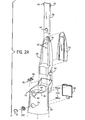
- FIGS. 2A and 2B are exploded perspective views of the sprayer of FIG. 1;
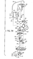
- FIG. 2C is an exploded perspective view of one possible pump used in the sprayer
- FIG. 3 is a side cross-sectional view of the sprayer taken along line 3-3 of FIG. 1;
- FIG. 4 is a partial cross-sectional view taken along line 4-4 of FIG. 3 showing the pump and drive mechanism with the pump and a drive motor shown in full;
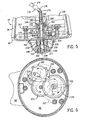
- FIG. 5 is a front cross-sectional view taken along line 5-5 of FIG. 3 showing the spray head drive and junction with the dispenser tube;
- FIG. 6 is a cross-sectional view taken along line 6-6 of FIG. 3 showing the gear train for the spray head drive;
- FIG. 7 is a schematic diagram showing the control circuit and cleanser flow path
- FIG. 8 is a partial reverse perspective view of the cleanser bottle with its bottle cap
- FIG. 9 is an enlarged view of the bottle-tray interface with the bottle seating in the tray and a discharge valve open;
- FIG. 10 is a view similar to FIG. 9 although with the bottle unseated from the tray and the discharge valve closed;
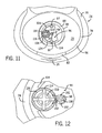
- FIG. 11 is a top view of the tray with the bottle removed
- FIG. 12 is an enlarged partial top view showing the discharge valve and piercing post.
- FIG. 13 is a cross-sectional view taken along line 13-13 of FIG. 10.
- the automated sprayer is generally referred to in the figures by reference number 20.
- the sprayer 20 includes as main components a bottle 22, a housing 24 with an adjustable hanger 26, a pump 28, a drive mechanism 30, a spray head 32 and a control circuit 34.
- the sprayer is typically suspended via the hanger from a shower spout or the like and then activated via a button 35 at the front of the sprayer to rotate a spray head and pump cleanser from the bottle out of the spray head during a spray cycle of a prescribed time period, after which dispensing is automatically terminated.
- the exterior of the sprayer is defined by the housing 24, which can be molded from, for example, plastic by any suitable technique and consists primarily of two pieces, a receptacle 36 and a hanger tower 38 that easily snaps into a pocket in the receptacle. This allows the sprayer to be shipped and stored in a compact package with minimal assembly by the consumer.
- the hanger tower 38 is an upright member defining a cavity in which the elongated body of the hanger 26 fits through an opening 40 at its upper end.
- the upper end of the hanger tower 38 has two oval openings 42 vertically spaced apart.
- a deflectable tab 44 formed in the lower end of the hanger can snap into one of the openings to lock the hanger at either of two extended positions.
- the hanger is extended and locked in the lower opening by simply pulling it away from the hanger tower. In this position, the sprayer 30 will hang from standard shower spouts at an appropriate height for spraying down the shower walls. The height can be adjusted by depressing the tab inwardly and sliding the hanger up or down.
- the hanger itself has two ears 46 at its upper end for mounting a rubber strap 48. The ears can be tapered to ease connection of the strap, which can have a series of holes at one end for adjustment purposes so that the strap fits tightly around a shower spout or the like.
- the back side of the hanger tower is closed by a back plate 50.
- the hanger tower connects to the receptacle at its lower end, which fits into a pocket 52 and has two latches 54 (one shown) that snap into two slots in the back of the receptacle.
- the receptacle defines an upwardly opening bottle tray 56 above a compartment 58 ( see FIG. 4) containing the pump and drive mechanism which is closed at the bottom by a cover 60.
- the cover has a circular skirted opening 62 for the spray head and a wall standoff 64 extending backward the distance of the pocket to brace the lower end of the receptacle against the wall and keep it plumb.
- the back side of the receptacle defines a battery compartment 66 with a lid 68 and the front side has an oval switch opening 70 for the control button 35.
- the tray 56 is formed to mate with a specially contoured upper end of the bottle.
- the bottle and tray are generally oval and have mating seating surfaces 72 and 74 and sloped shoulders 76 and 78 with complementary V-shaped features 80 and 82, respectively. These features and the contour of the shoulders fix the orientation of the bottle in the tray and make conventional cleanser bottles incompatible with proper operation of the sprayer.
- the tray defines a circular well 84 at the center of the seating surface 74 accommodating a special cap 86 screwed onto the mouth of the bottle.
- the well is formed with a shoulder portion 88, a vent nipple 90 and a recess 92 with a discharge nipple 94.
- the well supports a valve plate 96 ( see FIG. 2A) fastened thereto by two screws 97 ( see FIG. 3).
- the valve plate has a piercing post 98 projecting up from the valve plate.
- the post has a slanted top end defining a sharp point and defines a vent passageway 100 and three radial ribs 102.
- the vent passageway extends into a recess 104 at the underside of the valve plate accommodating a small o-ring 106 surrounding the vent passageway and the opening in the vent nipple 94.
- the valve plate also defines a valve recess 108 with a discharge passageway 110 through which a valve stem 112 extends.
- the upper end of the valve stem has a cross-shaped plunger 114 that is biased away from the well by a coil spring 116 fit into the valve recess.
- valve stem mounts a disc-shaped rubber gasket 118 retained by an enlarged end 120 of the valve stem.
- the plunger is biased upward by the spring so that the gasket seals against the underside of the valve plate so as to close off the discharge orifice when the sprayer is not being used.
- the valve plate also defines arcuate stand-offs 124 spaced in slightly from its periphery. The valve plate and the well are designed to cooperate with the specially designed bottle cap (described below) to discourage use of unaffiliated cleanser and thereby promote proper operation of the sprayer.
- the cap is generally circular with a serrated periphery 126 and a tapered sealing flange (or web) 128 that seals against the tray well above its shoulder.
- the top of the cap has an outer surface 130 with a recessed thinned area 132 at its center around which is a raised ring surface 134 extending to a plane spaced from surface 130.
- the thinned area 132 is located so that as the bottle is seated in the tray the piercing post will puncture the cap in this area to permit discharge of the cleanser and venting of the bottle.
- the raised ring is located to contact the plunger of the valve and push the valve downward to unseat the gasket from the plate and open the discharge orifice.
- the flat surface 130 of the cap rests on the stand-offs 124 to space the punctured area from the floor of the well.
- This arrangement thus provides a no-mess means of opening and inserting the bottle, but also further inhibits uses of improper cleanser containers. It does this for several reasons. First, if a conventional bottle and cap were inserted into the tray, the piercing post would not puncture a conventional cap lacking the weakened area. Even if the cap was removed so that the mouth was opened, the sprayer still would not operate because the valve is located radially inward of the place where a conventional thin-walled bottle mouth would normally extend so that the valve would not be opened.
- Another feature that serves this purpose is the conforming sloping of the bottle shape and receiving well. A bottle not having a complementary shape would not be received sufficiently low to activate the outlet valve.
- the cap has conventional internal threads 136 at its upper end that mate with threads 138 on the mouth of the bottle, and it also has a ring of one-way ratchet teeth 140 that engage corresponding ratchet teeth 142 on the bottle ( see FIG. 13).
- the ratchets allow the cap to be turned in a tightening direction but resist untightening rotation to prevent non-destructive removal of the cap and thus refilling of the bottle.
- FIGS 2B-6 show the pump, controller, and drive mechanism contained inside the receptacle compartment beneath the bottle tray. These components will now be described working from the bottle-tray interface to the spray head.
- a short vent tube 144 couples to the vent nipple 146 defining the vent orifice in the tray well.
- a small check valve 148 fits into the end of the vent tube. The check valve is normally closed so that cleanser does not leak out via that path. The valve opens by negative pressure that develops as cleanser is withdrawn from the bottle. The opened check valve aspirates the air to the bottle to allow the cleanser to flow from the bottle in a consistent manner, without introducing air in a manner that would cause foaming or gurgling. The check valve remains open until the pressure in the bottle has equalized sufficiently to alleviate the negative pressure and then it closes.
- a first tube 152 of a dispenser line 154 extends to an inlet barb 156 of the pump 28, which snaps into a support 158 mounted to the underside of the bottle tray.
- the pump can be any conventional pump, such as a diaphragm pump, a piston pump, a peristaltic pump, or even a gear pump as shown.
- the inlet defines a passageway leading between intermeshing drive gear 160 and idler gear 162 ( see FIG. 2C).
- the drive gear is connected to an upper shaft 164 (surrounded by o-ring 165) of a direct current motor 166 mounted through an opening in a gear plate 167 mounted to the lower cover of the receptacle.
- Operation of the motor rotates the drive gear which meshes with and turns the idler gear as conventional to draw cleanser from the bottle and through to an outlet barb 168.
- a second tube 170 connects the outlet barb to a filter 172.
- the filter accumulates cleanser within its housing and aids in priming the pump.
- a short tube 174 of the dispenser line connects the filter 172 to another check valve 176 which is connected by another short tube 178 continuing a spring 179 for support to an inlet barb 180 of a shaft junction 182.
- the stationary portion of the junction 182 is a chamber formed in part by the gear plate at a circular wall 184 having an inner shoulder 185 and covered at one end by a cap 186.
- the cap includes the inlet barb 180 and a raised annular ring 188 extending downwardly within the circular wall to press an o-ring 190 against the shoulder.
- the o-ring seals against the upper end of a rotating spray head drive shaft 192, which forms the rotating portion of the function.
- the drive shaft is an inverted Y-shaped structure with a cylindrical stem 194 defining a passageway 196 and a forked end 198 extending down through an opening in the receptacle cover and defining a gap 200 accommodating a spray nozzle 202.
- the forked end has lateral mounting posts 204 onto which snaps a dome-shaped cover 206 concealing the spray nozzle 202.
- the spray nozzle is preferably a fluidic oscillator providing oscillating spray (in this case up and down), however, any other suitable nozzle could be used. See e.g. U.S. patent 4,562,867 which shows examples of known fluidic oscillators.
- a fluid oscillator can be any suitably sized oscillator including a housing 208 with an inlet 210 and an outlet 212 on opposite sides.
- a barrier member (not shown) in the interior of the housing defines a passage between the inlet and the outlet so that cleanser entering the inlet passes through and around the barrier member to the outlet.
- the fluidic oscillator operates, as known in the art, by creating areas of low pressure at alternate sides of the passage through the barrier member to convert the straight flow entering the housing to an oscillating pattern.
- the nozzle is coupled to an outlet barb 214 extending from the stem by another tube 216.
- the nozzle is mounted so that its outlet end extends through the opening in the cover pointed downwardly at approximately a 30 degree angle.
- a drive gear 220 is press fit onto the stem of the drive shaft and meshes with a first reducer gear 222 which is rotated by another smaller diameter reducer gear 224 driven by a pinion 226 at the end of lower motor shaft 228.
- the gear train couples to the motor to the spray head at a reduced revolution per minute rate than the motor shaft. This arrangement provides a revolving, oscillating spray pattern.
- control circuitry 34 which is electrically coupled to a direct current power supply via battery terminals 230 ( see FIGS. 2A and 7) in the battery compartment and to the push-button switch 35, which is mounted through the opening 70 in the front of the receptacle through a lighted watertight, flexible membrane 232.
- the circuitry includes timing circuitry 234 and a speaker 236 that functions as described below.
- the electrical arrangement as well as the dispensing line and bottle venting flow paths are shown in FIG. 7 and the sprayer is operated as follows.
- a bottle is loaded into the sprayer (that is, the bottle is inverted and set into the receptacle tray)
- the thinned area of the bottle cap is punctured by the piercing post
- the cap sealing flange seals against the tray well
- the annular ring contacts and depresses the plunger of the discharge valve to open the valve.
- Cleanser pours out of the bottle between and around the ribs of the piercing post and is replaced by an equal volume of air through the vent tube.
- a user When a user wishes to spray the enclosure walls with cleanser, he or she simply depresses the switch at the front of the sprayer. This signals timing circuitry to begin a countdown delaying spraying for a predetermined time, such as 20 seconds. This affords the user time to exit the shower enclosure and close the doors or curtains. It also may provide the user time to abort the spray cycle by depressing the switch a second time. Initially depressing the switch may also send a pulsed tone to the speaker and flashes the lighted ring around the switch for warning the user of the impending operation of the sprayer.
- the spray cycle begins automatically at the expiration of the countdown.
- the motor is then energized which simultaneously rotates the drive gear of the pump and turns the gear train to rotate the drive shaft and the spray head.
- the pump draws cleanser from the bottle through the dispenser line and opens valve 176 so that cleanser can flow through the junction and be expelled through the nozzle as the spray head is rotated, thereby providing a circular, oscillating spray pattern. This reduces the level of cleanser in the bottle, creating a negative pressure in the bottle, which opens the check valve in the vent tube to aspirate the bottle and allow more cleanser to be drawn from the bottle during the spray cycle
- the motor continues to be energized until the expiration of a second countdown performed by the timing circuit, preferably another 20 second interval, automatically initiated by the timer. At that point the motor is deenergized which shuts down the pump causing valve 176 to close. Closing the valve prevents cleanser from leaking out of the dispenser line and also keeps the cleanser in the line upstream from the valve so that the pump remains primed. The sprayer thus returns to standby mode without further intervention from the user, ready for another spray cycle at the demand of the user
- a simple touch of a button initiates a spray cycle that terminates automatically on completion. Consumers do not need to spend time spraying the shower themselves, and there is less risk of exposure to the cleaning solution. All that is required to replenish the cleanser is simply to remove the old bottle, turn a new bottle upside down, and load it into the tray.
- the sprayer automatically meters out the proper volume of cleanser for the spray cycle.
- the volume can be easily altered for different sized enclosures by increasing or decreasing the duration of the spray cycle.
- the sprayer does not tie into the water supply lines. This makes the device easy to install in existing shower and tub enclosures at any suitable location in the enclosure. It can also be removably mounted without damaging the walls.
- the device can be used to dispense a cleaning or disinfecting solution in applications other than a tub/shower surround.
- U. S. patent 4,183,105 depicts how one type of automated cleansing equipment could be installed to clean the bowl.
- Such a structure should be considered to be an "enclosure" for purposes of this application.
- the invention provides assembly for coupling a fluid line to a rotatable nozzle which can be used in a sprayer for automatically spraying the walls of bath and shower enclosures and the like.
Landscapes
- Chemical & Material Sciences (AREA)
- Analytical Chemistry (AREA)
- Containers And Packaging Bodies Having A Special Means To Remove Contents (AREA)
Claims (4)
- Ensemble destiné à relier une conduite de fluide (170) à une buse rotative (202), l'ensemble comportant :une conduite d'entrée de fluide (170);une buse rotative (202);une chambre (182) fixée sur la conduite d'entrée de fluide (170); etun arbre ayant une extrémité reliée à la buse (202), l'arbre (192) étant à la fois rotatif et définissant un passage en communication avec la chambre (182) et la buse (202);caractérisé en ce que la chambre (182) est fixée en rotation par rapport à la conduite d'entrée de fluide (170), un joint (190) étant disposé à l'intérieur de la chambre (182), ledit arbre ayant une extrémité opposée disposée à l'intérieur de la chambre (182) autour de laquelle est disposé le joint (190).
- Ensemble selon la revendication 1, dans lequel le joint (190) est un joint torique (190) et un bouchon (186) est prévu en ayant une surface annulaire qui dépasse dans la chambre (182) radialement vers l'extérieur de l'arbre (192) de façon à venir en contact avec le joint torique (190) et presser le joint torique (190).
- Ensemble selon la revendication 1, dans lequel l'arbre est une structure en forme de Y inversé avec une extrémité fourchue (198) définissant un espace (200) recevant la buse de pulvérisation (202).
- Ensemble selon la revendication 3, dans lequel l'extrémité fourchue a des montants de montage latéraux (204) sur lesquels s'encliquette un couvercle en forme de dôme (206) qui masque la buse de pulvérisation (202).
Applications Claiming Priority (3)
| Application Number | Priority Date | Filing Date | Title |
|---|---|---|---|
| US38368702P | 2002-05-28 | 2002-05-28 | |
| US383687P | 2002-05-28 | ||
| EP03736929A EP1467820B1 (fr) | 2002-05-28 | 2003-05-21 | Pulverisateur automatise de nettoyage |
Related Parent Applications (2)
| Application Number | Title | Priority Date | Filing Date |
|---|---|---|---|
| EP03736929.5 Division | 2003-05-21 | ||
| EP03736929A Division EP1467820B1 (fr) | 2002-05-28 | 2003-05-21 | Pulverisateur automatise de nettoyage |
Publications (2)
| Publication Number | Publication Date |
|---|---|
| EP1570909A1 EP1570909A1 (fr) | 2005-09-07 |
| EP1570909B1 true EP1570909B1 (fr) | 2006-07-19 |
Family
ID=34751684
Family Applications (1)
| Application Number | Title | Priority Date | Filing Date |
|---|---|---|---|
| EP05008673A Expired - Lifetime EP1570909B1 (fr) | 2002-05-28 | 2003-05-21 | Assemblée pour coupler une canalisation hydraulique à une buse rotatif |
Country Status (1)
| Country | Link |
|---|---|
| EP (1) | EP1570909B1 (fr) |
Families Citing this family (1)
| Publication number | Priority date | Publication date | Assignee | Title |
|---|---|---|---|---|
| DE102018109980A1 (de) * | 2018-04-25 | 2019-10-31 | Alfred Kärcher SE & Co. KG | Sprühvorrichtung |
Family Cites Families (6)
| Publication number | Priority date | Publication date | Assignee | Title |
|---|---|---|---|---|
| US4383341A (en) | 1981-04-02 | 1983-05-17 | Murray Altman | Bathtub self-cleaning system |
| US4872225A (en) | 1988-09-06 | 1989-10-10 | Wagner John C | Cleaning apparatus and method for bath enclosures |
| US5390852A (en) * | 1993-04-22 | 1995-02-21 | Helen E. Schuenemann | Portable misting device having a rottable spray arm |
| US5536452A (en) | 1993-12-07 | 1996-07-16 | Black; Robert H. | Aqueous shower rinsing composition and a method for keeping showers clean |
| US5452485A (en) | 1994-08-02 | 1995-09-26 | Ross; Leslie | Gliding tub and shower cleaner |
| US5837664A (en) | 1996-07-16 | 1998-11-17 | Black; Robert H. | Aqueous shower rinsing composition and a method for keeping showers clean |
-
2003
- 2003-05-21 EP EP05008673A patent/EP1570909B1/fr not_active Expired - Lifetime
Also Published As
| Publication number | Publication date |
|---|---|
| EP1570909A1 (fr) | 2005-09-07 |
Similar Documents
| Publication | Publication Date | Title |
|---|---|---|
| EP1467820B1 (fr) | Pulverisateur automatise de nettoyage | |
| US6971549B2 (en) | Bottle adapter for dispensing of cleanser from bottle used in an automated cleansing sprayer | |
| US7021494B2 (en) | Automated cleansing sprayer having separate cleanser and air vent paths from bottle | |
| US7775458B2 (en) | Automated cleansing sprayer | |
| EP2162226B1 (fr) | Distributeur de produit fluide | |
| EP1570909B1 (fr) | Assemblée pour coupler une canalisation hydraulique à une buse rotatif | |
| CA2583647C (fr) | Pulverisateur automatise de nettoyage |
Legal Events
| Date | Code | Title | Description |
|---|---|---|---|
| PUAI | Public reference made under article 153(3) epc to a published international application that has entered the european phase |
Free format text: ORIGINAL CODE: 0009012 |
|
| 17P | Request for examination filed |
Effective date: 20050420 |
|
| AC | Divisional application: reference to earlier application |
Ref document number: 1467820 Country of ref document: EP Kind code of ref document: P |
|
| AK | Designated contracting states |
Kind code of ref document: A1 Designated state(s): AT BE BG CH CY CZ DE DK EE ES FI FR GB GR HU IE IT LI LU MC NL PT RO SE SI SK TR |
|
| AX | Request for extension of the european patent |
Extension state: AL LV MK |
|
| RIN1 | Information on inventor provided before grant (corrected) |
Inventor name: ALLEN, MICHAEL W. Inventor name: ROMANDY, MARK K. Inventor name: KOVARA, TERRY M. Inventor name: MAZOOJI, AMBER, N. D. Inventor name: BEVERLEY, STEPHEN D. Inventor name: BLANKENSHIP, PAUL M. Inventor name: NEUMANN, PETER M. |
|
| GRAP | Despatch of communication of intention to grant a patent |
Free format text: ORIGINAL CODE: EPIDOSNIGR1 |
|
| GRAS | Grant fee paid |
Free format text: ORIGINAL CODE: EPIDOSNIGR3 |
|
| AKX | Designation fees paid |
Designated state(s): AT BE BG CH CY CZ DE DK EE ES FI FR GB GR HU IE IT LI LU MC NL PT RO SE SI SK TR |
|
| GRAA | (expected) grant |
Free format text: ORIGINAL CODE: 0009210 |
|
| AC | Divisional application: reference to earlier application |
Ref document number: 1467820 Country of ref document: EP Kind code of ref document: P |
|
| AK | Designated contracting states |
Kind code of ref document: B1 Designated state(s): AT BE BG CH CY CZ DE DK EE ES FI FR GB GR HU IE IT LI LU MC NL PT RO SE SI SK TR |
|
| PG25 | Lapsed in a contracting state [announced via postgrant information from national office to epo] |
Ref country code: RO Free format text: LAPSE BECAUSE OF FAILURE TO SUBMIT A TRANSLATION OF THE DESCRIPTION OR TO PAY THE FEE WITHIN THE PRESCRIBED TIME-LIMIT Effective date: 20060719 Ref country code: CZ Free format text: LAPSE BECAUSE OF FAILURE TO SUBMIT A TRANSLATION OF THE DESCRIPTION OR TO PAY THE FEE WITHIN THE PRESCRIBED TIME-LIMIT Effective date: 20060719 Ref country code: AT Free format text: LAPSE BECAUSE OF FAILURE TO SUBMIT A TRANSLATION OF THE DESCRIPTION OR TO PAY THE FEE WITHIN THE PRESCRIBED TIME-LIMIT Effective date: 20060719 Ref country code: BE Free format text: LAPSE BECAUSE OF FAILURE TO SUBMIT A TRANSLATION OF THE DESCRIPTION OR TO PAY THE FEE WITHIN THE PRESCRIBED TIME-LIMIT Effective date: 20060719 Ref country code: SI Free format text: LAPSE BECAUSE OF FAILURE TO SUBMIT A TRANSLATION OF THE DESCRIPTION OR TO PAY THE FEE WITHIN THE PRESCRIBED TIME-LIMIT Effective date: 20060719 Ref country code: CH Free format text: LAPSE BECAUSE OF FAILURE TO SUBMIT A TRANSLATION OF THE DESCRIPTION OR TO PAY THE FEE WITHIN THE PRESCRIBED TIME-LIMIT Effective date: 20060719 Ref country code: FI Free format text: LAPSE BECAUSE OF FAILURE TO SUBMIT A TRANSLATION OF THE DESCRIPTION OR TO PAY THE FEE WITHIN THE PRESCRIBED TIME-LIMIT Effective date: 20060719 Ref country code: SK Free format text: LAPSE BECAUSE OF FAILURE TO SUBMIT A TRANSLATION OF THE DESCRIPTION OR TO PAY THE FEE WITHIN THE PRESCRIBED TIME-LIMIT Effective date: 20060719 Ref country code: LI Free format text: LAPSE BECAUSE OF FAILURE TO SUBMIT A TRANSLATION OF THE DESCRIPTION OR TO PAY THE FEE WITHIN THE PRESCRIBED TIME-LIMIT Effective date: 20060719 Ref country code: IT Free format text: LAPSE BECAUSE OF FAILURE TO SUBMIT A TRANSLATION OF THE DESCRIPTION OR TO PAY THE FEE WITHIN THE PRESCRIBED TIME-LIMIT;WARNING: LAPSES OF ITALIAN PATENTS WITH EFFECTIVE DATE BEFORE 2007 MAY HAVE OCCURRED AT ANY TIME BEFORE 2007. THE CORRECT EFFECTIVE DATE MAY BE DIFFERENT FROM THE ONE RECORDED. Effective date: 20060719 |
|
| REG | Reference to a national code |
Ref country code: GB Ref legal event code: FG4D |
|
| REG | Reference to a national code |
Ref country code: CH Ref legal event code: EP |
|
| REG | Reference to a national code |
Ref country code: IE Ref legal event code: FG4D |
|
| REF | Corresponds to: |
Ref document number: 60306958 Country of ref document: DE Date of ref document: 20060831 Kind code of ref document: P |
|
| PG25 | Lapsed in a contracting state [announced via postgrant information from national office to epo] |
Ref country code: DK Free format text: LAPSE BECAUSE OF FAILURE TO SUBMIT A TRANSLATION OF THE DESCRIPTION OR TO PAY THE FEE WITHIN THE PRESCRIBED TIME-LIMIT Effective date: 20061019 Ref country code: BG Free format text: LAPSE BECAUSE OF FAILURE TO SUBMIT A TRANSLATION OF THE DESCRIPTION OR TO PAY THE FEE WITHIN THE PRESCRIBED TIME-LIMIT Effective date: 20061019 Ref country code: SE Free format text: LAPSE BECAUSE OF FAILURE TO SUBMIT A TRANSLATION OF THE DESCRIPTION OR TO PAY THE FEE WITHIN THE PRESCRIBED TIME-LIMIT Effective date: 20061019 |
|
| PG25 | Lapsed in a contracting state [announced via postgrant information from national office to epo] |
Ref country code: PT Free format text: LAPSE BECAUSE OF FAILURE TO SUBMIT A TRANSLATION OF THE DESCRIPTION OR TO PAY THE FEE WITHIN THE PRESCRIBED TIME-LIMIT Effective date: 20061219 |
|
| REG | Reference to a national code |
Ref country code: ES Ref legal event code: FG2A Ref document number: 2264796 Country of ref document: ES Kind code of ref document: T3 |
|
| ET | Fr: translation filed | ||
| PLBE | No opposition filed within time limit |
Free format text: ORIGINAL CODE: 0009261 |
|
| STAA | Information on the status of an ep patent application or granted ep patent |
Free format text: STATUS: NO OPPOSITION FILED WITHIN TIME LIMIT |
|
| 26N | No opposition filed |
Effective date: 20070420 |
|
| PG25 | Lapsed in a contracting state [announced via postgrant information from national office to epo] |
Ref country code: MC Free format text: LAPSE BECAUSE OF NON-PAYMENT OF DUE FEES Effective date: 20070531 Ref country code: NL Free format text: LAPSE BECAUSE OF NON-PAYMENT OF DUE FEES Effective date: 20071201 |
|
| NLV4 | Nl: lapsed or anulled due to non-payment of the annual fee |
Effective date: 20071201 |
|
| PG25 | Lapsed in a contracting state [announced via postgrant information from national office to epo] |
Ref country code: GR Free format text: LAPSE BECAUSE OF FAILURE TO SUBMIT A TRANSLATION OF THE DESCRIPTION OR TO PAY THE FEE WITHIN THE PRESCRIBED TIME-LIMIT Effective date: 20061020 |
|
| PG25 | Lapsed in a contracting state [announced via postgrant information from national office to epo] |
Ref country code: IE Free format text: LAPSE BECAUSE OF NON-PAYMENT OF DUE FEES Effective date: 20070521 |
|
| PG25 | Lapsed in a contracting state [announced via postgrant information from national office to epo] |
Ref country code: EE Free format text: LAPSE BECAUSE OF FAILURE TO SUBMIT A TRANSLATION OF THE DESCRIPTION OR TO PAY THE FEE WITHIN THE PRESCRIBED TIME-LIMIT Effective date: 20060719 |
|
| PGFP | Annual fee paid to national office [announced via postgrant information from national office to epo] |
Ref country code: ES Payment date: 20080526 Year of fee payment: 6 |
|
| PGFP | Annual fee paid to national office [announced via postgrant information from national office to epo] |
Ref country code: IT Payment date: 20080527 Year of fee payment: 6 |
|
| PG25 | Lapsed in a contracting state [announced via postgrant information from national office to epo] |
Ref country code: CY Free format text: LAPSE BECAUSE OF FAILURE TO SUBMIT A TRANSLATION OF THE DESCRIPTION OR TO PAY THE FEE WITHIN THE PRESCRIBED TIME-LIMIT Effective date: 20060719 Ref country code: LU Free format text: LAPSE BECAUSE OF NON-PAYMENT OF DUE FEES Effective date: 20070521 |
|
| PG25 | Lapsed in a contracting state [announced via postgrant information from national office to epo] |
Ref country code: TR Free format text: LAPSE BECAUSE OF FAILURE TO SUBMIT A TRANSLATION OF THE DESCRIPTION OR TO PAY THE FEE WITHIN THE PRESCRIBED TIME-LIMIT Effective date: 20060719 Ref country code: HU Free format text: LAPSE BECAUSE OF FAILURE TO SUBMIT A TRANSLATION OF THE DESCRIPTION OR TO PAY THE FEE WITHIN THE PRESCRIBED TIME-LIMIT Effective date: 20070120 |
|
| REG | Reference to a national code |
Ref country code: ES Ref legal event code: FD2A Effective date: 20090522 |
|
| PG25 | Lapsed in a contracting state [announced via postgrant information from national office to epo] |
Ref country code: ES Free format text: LAPSE BECAUSE OF NON-PAYMENT OF DUE FEES Effective date: 20090522 |
|
| PG25 | Lapsed in a contracting state [announced via postgrant information from national office to epo] |
Ref country code: IT Free format text: LAPSE BECAUSE OF NON-PAYMENT OF DUE FEES Effective date: 20090521 |
|
| REG | Reference to a national code |
Ref country code: FR Ref legal event code: PLFP Year of fee payment: 14 |
|
| REG | Reference to a national code |
Ref country code: FR Ref legal event code: PLFP Year of fee payment: 15 |
|
| REG | Reference to a national code |
Ref country code: FR Ref legal event code: PLFP Year of fee payment: 16 |
|
| PGFP | Annual fee paid to national office [announced via postgrant information from national office to epo] |
Ref country code: GB Payment date: 20220426 Year of fee payment: 20 Ref country code: FR Payment date: 20220421 Year of fee payment: 20 Ref country code: DE Payment date: 20220420 Year of fee payment: 20 |
|
| REG | Reference to a national code |
Ref country code: DE Ref legal event code: R071 Ref document number: 60306958 Country of ref document: DE |
|
| REG | Reference to a national code |
Ref country code: GB Ref legal event code: PE20 Expiry date: 20230520 |
|
| P01 | Opt-out of the competence of the unified patent court (upc) registered |
Effective date: 20230528 |
|
| PG25 | Lapsed in a contracting state [announced via postgrant information from national office to epo] |
Ref country code: GB Free format text: LAPSE BECAUSE OF EXPIRATION OF PROTECTION Effective date: 20230520 |