EP1570723A1 - Austrageinrichtung mit einer Messeinrichtung - Google Patents
Austrageinrichtung mit einer Messeinrichtung Download PDFInfo
- Publication number
- EP1570723A1 EP1570723A1 EP05101578A EP05101578A EP1570723A1 EP 1570723 A1 EP1570723 A1 EP 1570723A1 EP 05101578 A EP05101578 A EP 05101578A EP 05101578 A EP05101578 A EP 05101578A EP 1570723 A1 EP1570723 A1 EP 1570723A1
- Authority
- EP
- European Patent Office
- Prior art keywords
- measuring device
- discharge device
- discharge
- housing
- cover
- Prior art date
- Legal status (The legal status is an assumption and is not a legal conclusion. Google has not performed a legal analysis and makes no representation as to the accuracy of the status listed.)
- Granted
Links
- 238000007599 discharging Methods 0.000 title 1
- 238000003306 harvesting Methods 0.000 claims description 7
- 239000004459 forage Substances 0.000 abstract description 2
- 241001124569 Lycaenidae Species 0.000 abstract 1
- 230000007613 environmental effect Effects 0.000 description 5
- 239000004615 ingredient Substances 0.000 description 5
- 240000008042 Zea mays Species 0.000 description 2
- 235000002017 Zea mays subsp mays Nutrition 0.000 description 2
- 239000000835 fiber Substances 0.000 description 2
- 210000002414 leg Anatomy 0.000 description 2
- 238000005259 measurement Methods 0.000 description 2
- XLYOFNOQVPJJNP-UHFFFAOYSA-N water Substances O XLYOFNOQVPJJNP-UHFFFAOYSA-N 0.000 description 2
- 244000025254 Cannabis sativa Species 0.000 description 1
- 235000019750 Crude protein Nutrition 0.000 description 1
- 229920002472 Starch Polymers 0.000 description 1
- 235000005824 Zea mays ssp. parviglumis Nutrition 0.000 description 1
- 235000016383 Zea mays subsp huehuetenangensis Nutrition 0.000 description 1
- 238000005299 abrasion Methods 0.000 description 1
- 230000005540 biological transmission Effects 0.000 description 1
- 238000005524 ceramic coating Methods 0.000 description 1
- 230000006835 compression Effects 0.000 description 1
- 238000007906 compression Methods 0.000 description 1
- 235000005822 corn Nutrition 0.000 description 1
- 239000013078 crystal Substances 0.000 description 1
- 230000001419 dependent effect Effects 0.000 description 1
- 238000001514 detection method Methods 0.000 description 1
- 238000011156 evaluation Methods 0.000 description 1
- 229910052500 inorganic mineral Inorganic materials 0.000 description 1
- 235000009973 maize Nutrition 0.000 description 1
- 239000000463 material Substances 0.000 description 1
- 239000002184 metal Substances 0.000 description 1
- 239000011707 mineral Substances 0.000 description 1
- 230000003287 optical effect Effects 0.000 description 1
- 239000011368 organic material Substances 0.000 description 1
- 230000000149 penetrating effect Effects 0.000 description 1
- 230000035515 penetration Effects 0.000 description 1
- 230000001681 protective effect Effects 0.000 description 1
- 229910052594 sapphire Inorganic materials 0.000 description 1
- 239000010980 sapphire Substances 0.000 description 1
- 238000007789 sealing Methods 0.000 description 1
- 235000019698 starch Nutrition 0.000 description 1
- 239000008107 starch Substances 0.000 description 1
- 239000000126 substance Substances 0.000 description 1
- 239000012780 transparent material Substances 0.000 description 1
- 210000000689 upper leg Anatomy 0.000 description 1
- 238000010792 warming Methods 0.000 description 1
Images


Classifications
-
- A—HUMAN NECESSITIES
- A01—AGRICULTURE; FORESTRY; ANIMAL HUSBANDRY; HUNTING; TRAPPING; FISHING
- A01D—HARVESTING; MOWING
- A01D43/00—Mowers combined with apparatus performing additional operations while mowing
- A01D43/08—Mowers combined with apparatus performing additional operations while mowing with means for cutting up the mown crop, e.g. forage harvesters
- A01D43/085—Control or measuring arrangements specially adapted therefor
-
- A—HUMAN NECESSITIES
- A01—AGRICULTURE; FORESTRY; ANIMAL HUSBANDRY; HUNTING; TRAPPING; FISHING
- A01D—HARVESTING; MOWING
- A01D41/00—Combines, i.e. harvesters or mowers combined with threshing devices
- A01D41/12—Details of combines
- A01D41/127—Control or measuring arrangements specially adapted for combines
- A01D41/1277—Control or measuring arrangements specially adapted for combines for measuring grain quality
Definitions
- the invention relates to a discharge of an agricultural Harvester, with a mounting arrangement, through the one arranged in a housing, for the detection of Properties of the crop established measuring device solvable attachable to the discharge device.
- Suitable for analyzing ingredients of organic material Measuring devices usually include light in the Wavelength range of near-infrared (NIR) working sensors, equipped with light sources and optical analyzers are. Such sensors are relatively complicated and expensive.
- NIR near-infrared
- Such measuring devices are described in WO 99/46971 A, WO 99/40419 A, WO 00/00818 A and DE 102 36 515 C. she are one within the harvester wearing structure Conveying channel adjacent arranged, promoted in the crop becomes. Since the measuring equipment there relatively well against environmental influences are arranged protected, more stable Protective housing for protection against environmental influences.
- EP 1 053 671 A describes such a measuring device described at an agricultural harvester is appropriate.
- the crop flows past the measuring device and is determined by the measuring device with regard to certain Properties such as moisture content or moisture content are investigated Content of organic ingredients.
- the measuring device on the discharge of a harvester attached.
- the measuring device can be dismantled, to use them on another harvester.
- a similar, removable measuring device shows the post-published DE 103 48 040 A.
- the measuring device when connected to the discharge device is attached, directly exposed to environmental influences. In unfavorable cases, for example when driving under trees on Field edge, the measuring device can also be damaged.
- a bracket assembly At the mounting arrangement The arranged in a housing measuring device is removable attached so that the measuring device in the assembled state the discharge device is positioned.
- the mounting arrangement is equipped with a cover, which serves to the spaced from the discharge device, the outer surface of the Cover the housing. The housing of the measuring device is located Thus, in the attached state between the cover and the discharge device.
- the covering rigid with the Discharge device could connect.
- the covering device could For example, be U-shaped, so that the measuring device in it is hineinschiebbar. It is then only a limited Access to the area of the discharge below the Cover possible, so that there arranged windows or Like. would be difficult to clean.
- the cover between a first position in which they the discharge device covering in the area in which the measuring device recording and a second position in which they can move not mentioned area of the discharge device. Thereby you get better access to the mentioned area of Discharge.
- the housing of the measuring device can on the cover be fixed so that the measuring device together with the Covering device between the first and second position is movable. In the second position there is a good accessibility to the measuring device, for example to clean it, wait or check. Since the measuring device at the Cover (releasable) is fixed, exists - other than when holding the measuring device by an operator in his hand would be - no danger that it could fall down. It would be also conceivable, the housing of the measuring device to the Discharge device or not with the cover moving, rigidly connected to the discharge parts to attach the bracket assembly.
- the covering device pivotally hinged to the discharge.
- the pivot axis can in the longitudinal direction of the discharge or across it run. Alternatively, a sliding attachment of the Covering on the discharge conceivable.
- the measuring device preferably operates optically, for example in the near infrared. It is therefore appropriate to have an opening in the Provide discharge, through which the measuring device can interact with the crop to be examined.
- an opening in the Provide discharge through which the measuring device can interact with the crop to be examined.
- the disc can through a bushing can be fixed, extending between the disk and the Edge of the opening of the discharge device is located.
- a Seal between the measuring device and the socket proposed. The bushing with the disc can be removed be so that unnecessary wear of the disc can be avoided can.
- the housing of the measuring device adjustable to attach to the bracket assembly. This can the measuring device is moved to an optimal position.
- a harvesting machine 10, shown in FIG. 1, in the manner of a self-propelled forage harvester builds on a frame 12, which is supported by front and rear wheels 14 and 16.
- the operation of the harvesting machine 10 is carried out by a driver's cab 18, from which a Erntegutingvortechnisch 20 visible is.
- a Erntegutingvortechnisch 20 visible is.
- the Erntegutingvorraum 20 in the illustrated embodiment is a maize header, from the ground recorded good, z.
- corn, grass or the like is one Chopper drum 22 fed, which chops it into small pieces and it gives up a conveyor device 24.
- Between the chopper drum 22 and the conveying device 24 extends a Nachzerklein ceremoniessvortechnischtechnisch 28, through which the good to be promoted Conveying device 24 is supplied tangentially.
- a first flow rate sensor 30 measures the Distance between two pre-press rollers 32, between the Erntegutaidvorides 20 and the cutterhead 22nd are arranged, and between which conveyed through the crop is, by means of one of the spring-suspended Prepress roller 32 actuated sliding or rotational resistance (Potentiometer). Furthermore, the speed of one of the pre-compression rollers 32 measured by a second sensor 34. In addition, sensors can drive the torque Conveyor 24 and the post-shredder 28th measure up.
- An on-board computer 40 connected to a display device 38 serves to record and evaluate the measured data.
- the Driving speed can be from the data of the propulsion devices the harvesting machine 10 or via a radar sensor 48th be recorded.
- a GPS Global Positioning System
- Sensors 42 for detecting the current position can be the yield mapped by means of the on-board computer 40 specific area become.
- a measuring device 46 for measurement certain ingredients of the crop at the discharge 26 arranged. It determines the percentage in operation These ingredients in the crop and works visually in Reflection operation in the visible range and / or near infrared range.
- On board computer 40 can thus water, Rohprotein-, Fat content etc. of the crop georeferenced and stored be displayed by the display device 38.
- the measuring device 46 is also set up, further parameters of the To grasp crop, namely the fiber length, the fiber content and the content of dry matter.
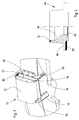
- the attachment of the measuring device 46 to the discharge chute 26 is shown in more detail in FIG.
- At the discharge device 26 are two in the longitudinal direction of the discharge device 26th spaced brackets 50 welded.
- a holding device 52 is attached between the consoles 50 .
- She is made up of one with the brackets 50 welded holding part 54, which are parallel extends to the adjacent surface of the discharge device 26, and a hinged on the holding part 54 hinged cover 56th in the figure 2 in their swung out (in Following: second) position is shown.
- the holding part 54 is additionally provided with thighs with oblong holes on which it is welded to the outer wall of the discharge device 26.
- the pivot axis 58 of the cover 56 extends along the longitudinal direction of the discharge device 26. It is also any other fastenings of the holding part 54 at the Discharge device 26 possible.
- the cover 56 has in the illustrated in Figure 2 Position a cross section with the shape of an inverted U. Between their lateral legs is a housing 60th arranged, which contains the measuring device 46.
- the housing 60 is solvable by a total of eight screws 62 on the side Legs of the cover 56 fixed.
- the screws 62 extend through slots in with the housing Mounts that a fine adjustment of the position of the housing 60th allow on the discharge device 26.
- an opening provided, which coincide with an opening in the holding part 54 is.
- a circular sleeve 64th arranged in the middle of a disc 66 is glued, the preferably made of sapphire crystal.
- the socket 64 is on her Bottom of the crop leading interior of the crop Discharge device 26 is arranged, with a Ceramic coating equipped to those due to abrasion To reduce wear of the bush 64 by crop.
- the Disc 66 is used in that of the measuring device 46 Wavelength transparent.
- a sensor surface 68 is on the Measuring device 46 arranged that they centric to the disc 66th is arranged when the cover 56 with the Measuring device 46 in a closed (hereinafter: first) Position is pivoted.
- the centric positioning of the Sensor surface 68 is through a funnel-shaped portion 78 at the inside of the sleeve 64 favors.
- Means for aligning the measuring device 46 at the Discharge device 26 and the holding part 54 may be provided, for. B. cooperating with pins or the like.
- the holding part 54 is by screws 70 with an on the Inside the discharge 26 arranged wear plate connected, located on the inside of the top in Figure 2 drawn cover plate of the discharge device 26 is located.
- the screws 70 allow a pulling on of the wear plate the cover plate of the discharge 26.
- the wear plate has an opening that matches the openings in the cover plate of the Discharge device 26 and in the holding part 54 is congruent.
- Endlagensperrriegel 72 At the side remote from the axis of rotation 58 of the holding part 54th are Endlagensperrriegel 72, with which the Cover device 56 can be fixed in the first position.
- the area of the discharge device 26 with a spent in the first, closed position cover 56 shown.
- the cover 56 is through the End-stop locking latch 72, the associated projecting portions 80th engage on the cover 56, in their position established.
- the sensor surface 68 of the measuring device 46 is aligned centrally with the socket 64.
- a seal 74 located at the Top of the sleeve 64 - and thus between the socket 64 and the housing 60 of the measuring device 46, a seal 74, the consists of elastic, non-translucent material and a Penetration of stray light prevented.
- Another seal 82 located between the socket 64 and the adjacent wall the discharge device 26.
- a flange 84 of the sleeve 64, on the the seal 82 abuts, is opposite the disc 66 upwards offset so that the disc 66 via the flange 84 and the adjacent areas of the discharge device 26 also in the Interior of the discharge device 26 protrudes.
- the socket 64 is only by the measuring device 60 to the discharge device 26th pressed.
- the second position of the cover presses the measuring device 46, the sleeve 64 against the discharge 26, wherein the seals 74, 82 compressed become.
- the switching elements to power the measuring device 46, to Evaluation of the measured values and data transmission via a Bus system of the harvester 10 includes.
- the power supply takes place via the bus system, whose not in the figures shown line through a cable shaft 76 introduced becomes.
- the bus system is connected by a plug connection with the Measuring device 64 connected.
- Located inside the housing 60 a light source that emits light downwards. The light passes through the permeable in the wavelength range used Disc 66 in the discharge chute 26, through the crop is encouraged.
- Detector Light reflected from the crop falls on one Detector in the housing 60 of the measuring device 46th From the Detector provided measurements calculated by the electronics unit the content of the crop of certain ingredients, such as water, starch, enzyme-soluble organic substances, non-organic minerals, crude protein, oil and the like.
- the measured values are transmitted via the bus system to the on-board computer 40 transferred, which maps them location-dependent, and to the display device 38, where they can be displayed.
- the cover 56 closes the housing 60 of the measuring device 46 sandwiched and protects them from environmental influences.
- the measuring device 46 heats up when exposed to sunlight not overly and she is facing rain and protected against mechanical influences.
- the swiveling attachment Allows an operator after releasing the Endlageensperrriegel 72, the cover 56 with the measuring device 46 from the in 3, the first position to the second position to spend, as shown in the figure 2. There it is Measuring device 46 is easily accessible, but is by the Cover device 56 held so they are not accidentally fall down and be damaged on impact with the ground can.
- the measuring device 46 of the Covering device After loosening the screws 62 and the electrical Plug connection, the measuring device 46 of the Covering device to be taken off in the evening or after Completing the harvest in a safe and environmentally-friendly way keep safe place or on another harvester or to use in a stationary use.
- the socket 64 with the Disc 66 can be removed to avoid unnecessary wear To avoid disc 66 and the bottom of the sleeve 64.
- a suitable closure piece be fixed from metal by means of screws 70.
Landscapes
- Life Sciences & Earth Sciences (AREA)
- Environmental Sciences (AREA)
- Investigating Or Analysing Materials By Optical Means (AREA)
- Harvesting Machines For Root Crops (AREA)
- Combines (AREA)
Abstract
Description
- Fig. 1
- eine Erntemaschine mit einer Messeinrichtung in Seitenansicht und in schematischer Darstellung,
- Fig. 2
- eine perspektivische Darstellung eines Abschnitts der Austrageinrichtung der Erntemaschine mit einer Halteeinrichtung und einer daran angebrachten Messeinrichtung in einer ausgeschwenkten Position,
- Fig. 3
- eine Darstellung der Austrageinrichtung aus Figur 2 bei einer in die Arbeitsposition verbrachten Messeinrichtung, und
- Fig. 4
- einen Schnitt durch eine Buchse mit einer Scheibe und zwei Dichtungen.
Claims (10)
- Austrageinrichtung (26) einer landwirtschaftlichen Erntemaschine (10), mit einer Halterungsanordnung (52), durch die eine in einem Gehäuse (60) angeordnete, zur Erfassung von Eigenschaften des Ernteguts eingerichtete Messeinrichtung (46) lösbar an der Austrageinrichtung (26) anbringbar ist, dadurch gekennzeichnet, dass die Halterungsanordnung (52) eine Abdeckeinrichtung (56) umfasst, mit welcher die von der Austrageinrichtung (26) abgewandte Fläche des Gehäuses (60) der Messeinrichtung (46) überdeckbar ist, so dass das Gehäuse (60) der Messeinrichtung (46) zwischen der Abdeckeinrichtung (56) und der Austrageinrichtung (56) anordenbar ist.
- Austrageinrichtung (26) nach Anspruch 1, dadurch gekennzeichnet, dass die Abdeckeinrichtung (56) zwischen einer ersten Position, in der sie Austrageinrichtung (26) und ggf. die dort angeordnete Messeinrichtung (46) überdeckt, und einer zweiten Position bewegbar ist, in sie die Austrageinrichtung (26) nicht überdeckt.
- Austrageinrichtung (26) nach Anspruch 1 oder 2, dadurch gekennzeichnet, dass das Gehäuse der Messeinrichtung (46) an der Abdeckeinrichtung (56) fixierbar ist.
- Austrageinrichtung (26) nach einem der Ansprüche 1 bis 3, dadurch gekennzeichnet, dass die Abdeckeinrichtung (56) schwenkbar an der Austrageinrichtung (26) angelenkt ist.
- Austrageinrichtung (26) nach einem der Ansprüche 1 bis 4, dadurch gekennzeichnet, dass sie mit einer Öffnung ausgestattet ist, durch die hindurch die Messeinrichtung (46) mit in der Austrageinrichtung (26) transportiertem Erntegut zusammenwirken kann, und dass in der Öffnung eine Scheibe (66) angeordnet ist.
- Austrageinrichtung (26) nach Anspruch 5, dadurch gekennzeichnet, dass eine Buchse (64) zwischen der Austrageinrichtung (26) und der Scheibe (66) angeordnet ist.
- Austrageinrichtung (26) nach Anspruch 5 oder 6, dadurch gekennzeichnet, dass zwischen dem Gehäuse (60) der Messeinrichtung (46) und der Buchse (64) eine Dichtung (74) vorgesehen ist.
- Austrageinrichtung (26) nach Anspruch 6 oder 7, dadurch gekennzeichnet, dass die Buchse (64) abnehmbar ist.
- Austrageinrichtung (26) nach einem der vorhergehenden Ansprüche, dadurch gekennzeichnet, dass die Position des Gehäuse (60) der Messeinrichtung (46) in der Halterungsanordnung (52) verstellbar ist.
- Austrageinrichtung (26) nach einem der vorhergehenden Ansprüche, dadurch gekennzeichnet, dass die Messeinrichtung (46) optisch arbeitet.
Applications Claiming Priority (2)
| Application Number | Priority Date | Filing Date | Title |
|---|---|---|---|
| DE102004010772 | 2004-03-05 | ||
| DE102004010772A DE102004010772A1 (de) | 2004-03-05 | 2004-03-05 | Austrageinrichtung mit einer Messeinrichtung |
Publications (2)
| Publication Number | Publication Date |
|---|---|
| EP1570723A1 true EP1570723A1 (de) | 2005-09-07 |
| EP1570723B1 EP1570723B1 (de) | 2007-10-24 |
Family
ID=34745401
Family Applications (1)
| Application Number | Title | Priority Date | Filing Date |
|---|---|---|---|
| EP05101578A Expired - Lifetime EP1570723B1 (de) | 2004-03-05 | 2005-03-02 | Austrageinrichtung mit einer Messeinrichtung |
Country Status (3)
| Country | Link |
|---|---|
| US (1) | US8317578B2 (de) |
| EP (1) | EP1570723B1 (de) |
| DE (2) | DE102004010772A1 (de) |
Cited By (9)
| Publication number | Priority date | Publication date | Assignee | Title |
|---|---|---|---|---|
| EP1989936A1 (de) * | 2007-05-11 | 2008-11-12 | CLAAS Selbstfahrende Erntemaschinen GmbH | Messeinrichtung zur Inhaltsstofferfassung von landwirtschaftlichem Erntegut |
| US7859674B2 (en) | 2006-11-20 | 2010-12-28 | Pioneer Hi-Bred International, Inc. | System and method for measuring a harvest quality parameter on a harvesting device |
| CN103868875A (zh) * | 2012-12-17 | 2014-06-18 | 北京普源精电科技有限公司 | 一种具有定位功能的紫外分光光度计 |
| US8961283B2 (en) | 2011-10-27 | 2015-02-24 | Claas Selbstfahrende Erntemaschinen Gmbh | Agricultural harvesting machine |
| EP3158849A1 (de) * | 2015-10-23 | 2017-04-26 | Carnegie Mellon University | System zur bewertung von landwirtschaftlichem material |
| US10188036B2 (en) | 2015-10-23 | 2019-01-29 | Carnegie Mellon University | System for evaluating agricultural material |
| EP3489632B1 (de) * | 2017-11-22 | 2021-07-14 | CLAAS Selbstfahrende Erntemaschinen GmbH | Messvorrichtung zur bestimmung eines aus schüttgut bestehenden massenstroms |
| EP4147561A1 (de) * | 2021-09-13 | 2023-03-15 | CLAAS E-Systems GmbH | Landwirtschaftliche arbeitsmaschine sowie verfahren zur ausrichtung einer zugehörigen überwachungseinheit |
| EP4147560A1 (de) * | 2021-09-14 | 2023-03-15 | CLAAS E-Systems GmbH | Messvorrichtung für einen durch eine erntemaschine geförderten materialstrom |
Families Citing this family (8)
| Publication number | Priority date | Publication date | Assignee | Title |
|---|---|---|---|---|
| DE102010047103A1 (de) * | 2010-09-29 | 2012-03-29 | Carl Zeiss Jena Gmbh | Flansch zum Abschluss eines optischen Geräts gegenüber einem Probenstrom und optisches Gerät zur teilweisen Anordnung in einem Probenstrom |
| US20140365170A1 (en) * | 2013-03-15 | 2014-12-11 | Unverferth Manufacturing Company, Inc. | Grain cart with intergrated moisture sensor |
| BE1024954B1 (nl) * | 2017-07-03 | 2018-08-23 | Cnh Industrial Belgium Nv | Regeling voor het lossen van gewas voor een veldhakselaar |
| DE102018216498A1 (de) | 2018-09-26 | 2020-03-26 | Deere & Company | Anordnung zur sensorischen Untersuchung einer fließfähigen Probe |
| US11160208B2 (en) * | 2019-04-29 | 2021-11-02 | Deere & Company | Method and apparatus for sensing crop material in a harvester |
| EP4066621A1 (de) * | 2021-03-31 | 2022-10-05 | CNH Industrial Belgium N.V. | Selbstfahrender mählader mit mitteln zur verminderung von stutzenverstopfungen |
| DE102023124880A1 (de) * | 2023-09-14 | 2025-03-20 | Claas Saulgau Gmbh | Landwirtschaftliche Maschine |
| EP4714248A1 (de) * | 2024-09-18 | 2026-03-25 | CNH Industrial Belgium N.V. | Überwachungsanordnung für ein landwirtschaftliches gerät |
Citations (6)
| Publication number | Priority date | Publication date | Assignee | Title |
|---|---|---|---|---|
| WO1999040419A1 (en) | 1998-02-06 | 1999-08-12 | Dsquared Development, Inc. | Grain quality monitor |
| WO1999046971A1 (en) | 1998-03-16 | 1999-09-23 | Pioneer Hi-Bred International, Inc. | Near infrared spectrometer used in combination with a combine for real time grain analysis |
| WO2000000818A1 (en) | 1998-06-29 | 2000-01-06 | Deere & Company | Optoelectronic apparatus for detecting damaged grain |
| EP1053671A1 (de) | 1999-05-19 | 2000-11-22 | Deere & Company | Messeinrichtung zur Messung von Inhaltsstoffen in und/oder Eigenschaften von Erntegut |
| DE10236515C1 (de) | 2002-08-09 | 2003-09-25 | Case Harvesting Sys Gmbh | Verfahren und Meßeinrichtung zur Bestimmung von Inhaltsstoffen und/oder Eigenschaften von Erntegut in Häckslern |
| US20050085283A1 (en) * | 2003-10-15 | 2005-04-21 | Deere & Company, A Delaware Corporation | Crop measuring arrangement |
Family Cites Families (12)
| Publication number | Priority date | Publication date | Assignee | Title |
|---|---|---|---|---|
| US85283A (en) * | 1868-12-29 | Improved blacksmiths forge | ||
| US3610252A (en) * | 1967-12-05 | 1971-10-05 | Clayson Nv | Apparatus for measuring quantities of granular material such as corn grains or similar crops |
| US4068223A (en) * | 1975-07-10 | 1978-01-10 | Dickey-John Corporation | Monitor system for agricultural harvesting apparatus |
| US5235168A (en) * | 1991-06-24 | 1993-08-10 | Spectra-Physics Scanning Systems, Inc. | Bar code scanner housing assembly |
| US5256873A (en) * | 1992-09-03 | 1993-10-26 | Eaton Corporation | Multiple station through beam photoelectric sensor |
| US5506922A (en) | 1994-08-01 | 1996-04-09 | Molex Incorporated | Fiber optic component assembly with a movable protective shield |
| US5915015A (en) | 1996-09-10 | 1999-06-22 | Ericsson, Inc. | Telephone having sealed acoustical passageway through flip cover hinge |
| DE19802756B4 (de) | 1998-01-26 | 2004-04-22 | Claas Selbstfahrende Erntemaschinen Gmbh | Fördervolumen-Meßvorrichtung eines Elevators, insbes. für Erntegut |
| US6254008B1 (en) * | 1999-05-14 | 2001-07-03 | Honeywell International, Inc. | Board mounted sensor placement into a furnace duct |
| US6421990B1 (en) * | 1999-05-19 | 2002-07-23 | Deere & Company | Measuring device for measuring components in and/or properties of crop material |
| US6640657B1 (en) * | 2001-12-14 | 2003-11-04 | Torque-Traction Technologies, Inc. | Fixture for supporting a sensing device on a movable article |
| DE10204702A1 (de) | 2002-02-05 | 2003-08-14 | Claas Selbstfahr Erntemasch | Ortungssystem an selbstfahrenden landwirtschaftlichen Arbeitsmaschinen |
-
2004
- 2004-03-05 DE DE102004010772A patent/DE102004010772A1/de not_active Withdrawn
-
2005
- 2005-03-02 EP EP05101578A patent/EP1570723B1/de not_active Expired - Lifetime
- 2005-03-02 DE DE502005001759T patent/DE502005001759D1/de not_active Expired - Lifetime
- 2005-03-04 US US11/072,890 patent/US8317578B2/en active Active
Patent Citations (7)
| Publication number | Priority date | Publication date | Assignee | Title |
|---|---|---|---|---|
| WO1999040419A1 (en) | 1998-02-06 | 1999-08-12 | Dsquared Development, Inc. | Grain quality monitor |
| WO1999046971A1 (en) | 1998-03-16 | 1999-09-23 | Pioneer Hi-Bred International, Inc. | Near infrared spectrometer used in combination with a combine for real time grain analysis |
| WO2000000818A1 (en) | 1998-06-29 | 2000-01-06 | Deere & Company | Optoelectronic apparatus for detecting damaged grain |
| EP1053671A1 (de) | 1999-05-19 | 2000-11-22 | Deere & Company | Messeinrichtung zur Messung von Inhaltsstoffen in und/oder Eigenschaften von Erntegut |
| DE10236515C1 (de) | 2002-08-09 | 2003-09-25 | Case Harvesting Sys Gmbh | Verfahren und Meßeinrichtung zur Bestimmung von Inhaltsstoffen und/oder Eigenschaften von Erntegut in Häckslern |
| US20050085283A1 (en) * | 2003-10-15 | 2005-04-21 | Deere & Company, A Delaware Corporation | Crop measuring arrangement |
| DE10348040A1 (de) | 2003-10-15 | 2005-05-19 | Deere & Company, Moline | Messeinrichtung |
Cited By (12)
| Publication number | Priority date | Publication date | Assignee | Title |
|---|---|---|---|---|
| US7859674B2 (en) | 2006-11-20 | 2010-12-28 | Pioneer Hi-Bred International, Inc. | System and method for measuring a harvest quality parameter on a harvesting device |
| EP1989936A1 (de) * | 2007-05-11 | 2008-11-12 | CLAAS Selbstfahrende Erntemaschinen GmbH | Messeinrichtung zur Inhaltsstofferfassung von landwirtschaftlichem Erntegut |
| US8961283B2 (en) | 2011-10-27 | 2015-02-24 | Claas Selbstfahrende Erntemaschinen Gmbh | Agricultural harvesting machine |
| RU2596970C2 (ru) * | 2011-10-27 | 2016-09-10 | КЛААС Зельбстфаренде Эрнтемашинен ГмбХ | Сельскохозяйственная уборочная машина |
| CN103868875A (zh) * | 2012-12-17 | 2014-06-18 | 北京普源精电科技有限公司 | 一种具有定位功能的紫外分光光度计 |
| CN103868875B (zh) * | 2012-12-17 | 2018-09-25 | 苏州普源精电科技有限公司 | 一种具有定位功能的紫外分光光度计 |
| EP3158849A1 (de) * | 2015-10-23 | 2017-04-26 | Carnegie Mellon University | System zur bewertung von landwirtschaftlichem material |
| US10172285B2 (en) | 2015-10-23 | 2019-01-08 | Carnegie Mellon University | System for evaluating agricultural material |
| US10188036B2 (en) | 2015-10-23 | 2019-01-29 | Carnegie Mellon University | System for evaluating agricultural material |
| EP3489632B1 (de) * | 2017-11-22 | 2021-07-14 | CLAAS Selbstfahrende Erntemaschinen GmbH | Messvorrichtung zur bestimmung eines aus schüttgut bestehenden massenstroms |
| EP4147561A1 (de) * | 2021-09-13 | 2023-03-15 | CLAAS E-Systems GmbH | Landwirtschaftliche arbeitsmaschine sowie verfahren zur ausrichtung einer zugehörigen überwachungseinheit |
| EP4147560A1 (de) * | 2021-09-14 | 2023-03-15 | CLAAS E-Systems GmbH | Messvorrichtung für einen durch eine erntemaschine geförderten materialstrom |
Also Published As
| Publication number | Publication date |
|---|---|
| EP1570723B1 (de) | 2007-10-24 |
| US20050195406A1 (en) | 2005-09-08 |
| US8317578B2 (en) | 2012-11-27 |
| DE502005001759D1 (de) | 2007-12-06 |
| DE102004010772A1 (de) | 2005-10-06 |
Similar Documents
| Publication | Publication Date | Title |
|---|---|---|
| EP1570723B1 (de) | Austrageinrichtung mit einer Messeinrichtung | |
| EP1523874B1 (de) | Messeinrichtung zur Messung von Inhaltsstoffen in Erntegut | |
| DE19922867B4 (de) | Erntemaschine mit einer Meßeinrichtung zur Messung von Inhaltsstoffen in und/oder Eigenschaften von Erntegut | |
| EP3444577B1 (de) | Spektrometrischer messkopf für forst-, land- und lebensmittelwirtschaftliche anwendungen | |
| EP2586285B1 (de) | Landwirtschaftliche erntemaschine | |
| DE102004038404B4 (de) | Einrichtung zur selbsttätigen Einstellung der Schnitthöhe eines Erntevorsatzes zur Ernte stängelartiger Pflanzen | |
| EP1956361B1 (de) | Messeinrichtung zur optischen und spektroskopischen Untersuchung einer Probe | |
| DE102004038408A1 (de) | Messeinrichtung | |
| DE102004048103A1 (de) | Spektrometrischer Messkopf für Erntemaschinen und andere landwirtschaftlich genutzte Maschinen | |
| EP1038429A1 (de) | Einrichtung zur Messung des Kornanteiles in der Überkehr eines Mähdreschers | |
| DE60004394T2 (de) | System zum messen von bestandteilen | |
| EP1892520A1 (de) | Messvorrichtung zur Inhaltsstofferfassung | |
| DE102015215299A1 (de) | Messeinrichtung zur Untersuchung geernteten Korns in einem Mähdrescher | |
| DE102005039596B4 (de) | Landwirtschaftliche Erntemaschine | |
| DE2444550A1 (de) | Maehdrescher mit haecksler | |
| EP2974587B1 (de) | Landwirtschaftliche erntemaschine | |
| DE102006050663A1 (de) | Messvorrichtung zur Messung von Parametern | |
| DE10154874C2 (de) | Durchsatzmeßvorrichtung in einer Erntemaschine | |
| DE102023123645A1 (de) | Landwirtschaftliche Erntemaschine und Verfahren zur Bestimmung mindestens einer Eigenschaft von Erntegut | |
| DE102018004219A1 (de) | Landwirtschaftliche Erntemaschine | |
| WO2026104725A1 (de) | Landwirtschaftliches mähsystem | |
| DE102024133722A1 (de) | Landwirtschafliches Mähsystem | |
| DE102005017121A1 (de) | Auswurfkrümmer für einen Feldhäcksler |
Legal Events
| Date | Code | Title | Description |
|---|---|---|---|
| PUAI | Public reference made under article 153(3) epc to a published international application that has entered the european phase |
Free format text: ORIGINAL CODE: 0009012 |
|
| AK | Designated contracting states |
Kind code of ref document: A1 Designated state(s): AT BE BG CH CY CZ DE DK EE ES FI FR GB GR HU IE IS IT LI LT LU MC NL PL PT RO SE SI SK TR |
|
| AX | Request for extension of the european patent |
Extension state: AL BA HR LV MK YU |
|
| 17P | Request for examination filed |
Effective date: 20060307 |
|
| AKX | Designation fees paid |
Designated state(s): BE DE FR GB IT |
|
| GRAP | Despatch of communication of intention to grant a patent |
Free format text: ORIGINAL CODE: EPIDOSNIGR1 |
|
| GRAS | Grant fee paid |
Free format text: ORIGINAL CODE: EPIDOSNIGR3 |
|
| GRAA | (expected) grant |
Free format text: ORIGINAL CODE: 0009210 |
|
| AK | Designated contracting states |
Kind code of ref document: B1 Designated state(s): BE DE FR GB IT |
|
| REG | Reference to a national code |
Ref country code: GB Ref legal event code: FG4D Free format text: NOT ENGLISH |
|
| REF | Corresponds to: |
Ref document number: 502005001759 Country of ref document: DE Date of ref document: 20071206 Kind code of ref document: P |
|
| GBT | Gb: translation of ep patent filed (gb section 77(6)(a)/1977) |
Effective date: 20071219 |
|
| ET | Fr: translation filed | ||
| PLBE | No opposition filed within time limit |
Free format text: ORIGINAL CODE: 0009261 |
|
| STAA | Information on the status of an ep patent application or granted ep patent |
Free format text: STATUS: NO OPPOSITION FILED WITHIN TIME LIMIT |
|
| 26N | No opposition filed |
Effective date: 20080725 |
|
| PGFP | Annual fee paid to national office [announced via postgrant information from national office to epo] |
Ref country code: IT Payment date: 20100325 Year of fee payment: 6 |
|
| PG25 | Lapsed in a contracting state [announced via postgrant information from national office to epo] |
Ref country code: IT Free format text: LAPSE BECAUSE OF NON-PAYMENT OF DUE FEES Effective date: 20110302 |
|
| REG | Reference to a national code |
Ref country code: FR Ref legal event code: PLFP Year of fee payment: 12 |
|
| REG | Reference to a national code |
Ref country code: FR Ref legal event code: PLFP Year of fee payment: 13 |
|
| REG | Reference to a national code |
Ref country code: FR Ref legal event code: PLFP Year of fee payment: 14 |
|
| PGFP | Annual fee paid to national office [announced via postgrant information from national office to epo] |
Ref country code: BE Payment date: 20190327 Year of fee payment: 15 |
|
| REG | Reference to a national code |
Ref country code: DE Ref legal event code: R084 Ref document number: 502005001759 Country of ref document: DE |
|
| REG | Reference to a national code |
Ref country code: BE Ref legal event code: MM Effective date: 20200331 |
|
| PG25 | Lapsed in a contracting state [announced via postgrant information from national office to epo] |
Ref country code: BE Free format text: LAPSE BECAUSE OF NON-PAYMENT OF DUE FEES Effective date: 20200331 |
|
| PGFP | Annual fee paid to national office [announced via postgrant information from national office to epo] |
Ref country code: FR Payment date: 20210325 Year of fee payment: 17 |
|
| PGFP | Annual fee paid to national office [announced via postgrant information from national office to epo] |
Ref country code: GB Payment date: 20210329 Year of fee payment: 17 |
|
| GBPC | Gb: european patent ceased through non-payment of renewal fee |
Effective date: 20220302 |
|
| PG25 | Lapsed in a contracting state [announced via postgrant information from national office to epo] |
Ref country code: GB Free format text: LAPSE BECAUSE OF NON-PAYMENT OF DUE FEES Effective date: 20220302 Ref country code: FR Free format text: LAPSE BECAUSE OF NON-PAYMENT OF DUE FEES Effective date: 20220331 |
|
| PGFP | Annual fee paid to national office [announced via postgrant information from national office to epo] |
Ref country code: DE Payment date: 20240221 Year of fee payment: 20 |
|
| REG | Reference to a national code |
Ref country code: DE Ref legal event code: R071 Ref document number: 502005001759 Country of ref document: DE |