EP1570288B1 - Signaldeformationsmonitor - Google Patents
Signaldeformationsmonitor Download PDFInfo
- Publication number
- EP1570288B1 EP1570288B1 EP03755852.5A EP03755852A EP1570288B1 EP 1570288 B1 EP1570288 B1 EP 1570288B1 EP 03755852 A EP03755852 A EP 03755852A EP 1570288 B1 EP1570288 B1 EP 1570288B1
- Authority
- EP
- European Patent Office
- Prior art keywords
- correlation
- measurements
- lgf
- signal deformation
- satellites
- Prior art date
- Legal status (The legal status is an assumption and is not a legal conclusion. Google has not performed a legal analysis and makes no representation as to the accuracy of the status listed.)
- Expired - Lifetime
Links
- 238000005259 measurement Methods 0.000 claims description 55
- 238000012544 monitoring process Methods 0.000 claims description 11
- 230000009466 transformation Effects 0.000 claims description 7
- 238000010586 diagram Methods 0.000 description 6
- 238000013459 approach Methods 0.000 description 5
- 238000000034 method Methods 0.000 description 5
- 238000012937 correction Methods 0.000 description 4
- 230000003416 augmentation Effects 0.000 description 3
- 238000001514 detection method Methods 0.000 description 2
- 238000012423 maintenance Methods 0.000 description 2
- 230000009286 beneficial effect Effects 0.000 description 1
- 230000005540 biological transmission Effects 0.000 description 1
- 238000004364 calculation method Methods 0.000 description 1
- 238000006243 chemical reaction Methods 0.000 description 1
- 238000004891 communication Methods 0.000 description 1
- 238000013461 design Methods 0.000 description 1
- 230000000694 effects Effects 0.000 description 1
- 230000007613 environmental effect Effects 0.000 description 1
- 230000002349 favourable effect Effects 0.000 description 1
- 238000007689 inspection Methods 0.000 description 1
- 238000012545 processing Methods 0.000 description 1
- 230000001052 transient effect Effects 0.000 description 1
Images


Classifications
-
- G—PHYSICS
- G01—MEASURING; TESTING
- G01S—RADIO DIRECTION-FINDING; RADIO NAVIGATION; DETERMINING DISTANCE OR VELOCITY BY USE OF RADIO WAVES; LOCATING OR PRESENCE-DETECTING BY USE OF THE REFLECTION OR RERADIATION OF RADIO WAVES; ANALOGOUS ARRANGEMENTS USING OTHER WAVES
- G01S19/00—Satellite radio beacon positioning systems; Determining position, velocity or attitude using signals transmitted by such systems
- G01S19/01—Satellite radio beacon positioning systems transmitting time-stamped messages, e.g. GPS [Global Positioning System], GLONASS [Global Orbiting Navigation Satellite System] or GALILEO
- G01S19/13—Receivers
- G01S19/21—Interference related issues ; Issues related to cross-correlation, spoofing or other methods of denial of service
-
- G—PHYSICS
- G01—MEASURING; TESTING
- G01S—RADIO DIRECTION-FINDING; RADIO NAVIGATION; DETERMINING DISTANCE OR VELOCITY BY USE OF RADIO WAVES; LOCATING OR PRESENCE-DETECTING BY USE OF THE REFLECTION OR RERADIATION OF RADIO WAVES; ANALOGOUS ARRANGEMENTS USING OTHER WAVES
- G01S19/00—Satellite radio beacon positioning systems; Determining position, velocity or attitude using signals transmitted by such systems
- G01S19/01—Satellite radio beacon positioning systems transmitting time-stamped messages, e.g. GPS [Global Positioning System], GLONASS [Global Orbiting Navigation Satellite System] or GALILEO
- G01S19/015—Arrangements for jamming, spoofing or other methods of denial of service of such systems
-
- G—PHYSICS
- G01—MEASURING; TESTING
- G01S—RADIO DIRECTION-FINDING; RADIO NAVIGATION; DETERMINING DISTANCE OR VELOCITY BY USE OF RADIO WAVES; LOCATING OR PRESENCE-DETECTING BY USE OF THE REFLECTION OR RERADIATION OF RADIO WAVES; ANALOGOUS ARRANGEMENTS USING OTHER WAVES
- G01S19/00—Satellite radio beacon positioning systems; Determining position, velocity or attitude using signals transmitted by such systems
- G01S19/01—Satellite radio beacon positioning systems transmitting time-stamped messages, e.g. GPS [Global Positioning System], GLONASS [Global Orbiting Navigation Satellite System] or GALILEO
- G01S19/13—Receivers
- G01S19/23—Testing, monitoring, correcting or calibrating of receiver elements
Definitions
- the present invention relates generally to satellite systems, and more particularly, relates to monitoring satellite signal deformation.
- Pilots typically use landing navigation systems when they are landing an aircraft. These systems assist the pilot in maintaining the aircraft along a predetermined glide path associated with a particular landing strip or runway. In general, ground-based navigational systems are employed. Two common ground-based navigation systems currently in use are the Instrument Landing System (ILS) and the Microwave Landing System (MLS).
- ILS Instrument Landing System
- MLS Microwave Landing System
- LAAS Local Area Augmentation System
- the LAAS uses a differential global positioning system (DGPS).
- the DGPS includes a global positioning system (GPS) and at least one ground station.
- GPS uses a number of orbiting satellites and a receiver on an aircraft to determine the position of the aircraft with respect to ground. With the satellite information, the receiver can determine the position, speed, and altitude of the aircraft.
- the DGPS can correct errors that may occur in the transmission of data from the satellites to the receiver. As a result the DGPS can determine the position of the aircraft with a high degree of accuracy.
- the FAA initiated a program to develop requirements for developing and deploying a LAAS Ground Facility (LGF).
- LGF will monitor the satellite constellation, provide the LAAS corrections and integrity data, and provide approach data to and interface with air traffic control.
- the FAA released Specification FAA-E- 2937A, for a Category I LGF on April 17,2002. This specification establishes the performance requirements for the LGF.
- the LGF specification has identified signal deformation as a threat to the LGF that must be handled to ensure accuracy and integrity of the LAAS. Satellite signal deformations that occur in the front end of the receiver (i. e. before digitization in a receiver) typically can be ignored since they are common to all satellites. However, this front end signal deformation may bias correlation measurements used for monitoring signal deformation. Experimental data has shown that there is a variation between individual receivers of the same type and over time due to temperature variations. To avoid having to characterize every individual receiver over the operational temperature range it would be beneficial to have a method of monitoring satellite signal deformation that corrects for bias to the correlation measurements caused by the front end signal deformation.
- WO 02/39136 A2 discloses apparatus for navigation satellite signal quality monitoring.
- EP 0 535 570 A1 discloses transient detection processing for underwater acoustic signal recognition.
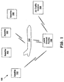
- Fig. 1 is a pictorial representation of a Local Area Augmentation System (LAAS) 100, which augments a differential global positioning satellite (DGPS) system.
- the LAAS 100 includes a plurality of satellites 102 and a LAAS Ground Facility (LGF) 106 for providing precision approach data and landing capability to an aircraft 104. While Fig. 1 depicts four satellites, the plurality of satellites 102 may include any number of satellites currently orbiting the earth and any new satellites that are installed in the future.
- the LAAS 100 may also include additional components not depicted in Fig. 1 .
- the satellites 102 may provide the aircraft 104 and the LGF 106 with GPS ranging signals and orbital parameters. Additionally, the LGF 106 may provide differential corrections, integrity parameters, and precision approach pathpoint data to the aircraft 104. The aircraft 104 may apply the LGF corrections to the GPS ranging signals to accurately determine its position. The aircraft 104 may use an on-board GPS receiver(s) (not shown) to receive the ranging signals and to calculate an estimate of its position. Communication between the LGF and the aircraft 104 may be conducted using Very High Frequency (VHF) Data Broadcast (VDB).
- VHF Very High Frequency
- VDB Very High Frequency Data Broadcast
- the LGF 106 may provide status information to air traffic control 108 via an Air Traffic Control Unit (ATCU) (not shown).
- ATCU Air Traffic Control Unit
- the ATCU provides air traffic controllers with LGF status information and runway control capabilities.
- LGF status information may also be available on a Local Status Panel (LSP) (not shown).
- LSP Local Status Panel
- Fig. 2 depicts a block diagram of an exemplary LGF 200.
- the LGF 200 includes at least one reference receiver (RR) 202, a DGPS Cabinet 204, and at least one VDB Cabinet 206.
- the LGF 200 may include additional components not depicted in Fig. 2 .
- the RR 202 may include a receiver 208, which may obtain information from the satellites 102 using an antenna.
- the receiver 208 may include multiple channels to simultaneously track signals from the satellites 102. Typically, the receiver 208 includes five to twenty-four tracking channels, but may include more or less depending on its design.
- Each tracking channel includes a tracking loop, which may include a code tracking loop and a carrier tracking loop.
- the code tracking loop may operate to keep incoming satellite code in phase with a replica code generated at the receiver 208, while the carrier tracking loop may operate to keep the incoming satellite carrier signal in phase and/or frequency with a replica carrier signal.
- the RR 202 may also include a power supply and additional components not depicted in Fig. 2 .
- the DGPS Cabinet 204 may communicate with the RR 202, the ATCU, the VDB Cabinet 206, environmental sensors, and a National Airspace System (NAS) Infrastructure Management System (NIMS).
- the DGPS Cabinet 204 may include a Maintenance Data Terminal (MDT), a Local Status Panel (LSP), an Input/Output controller, a processor, an auxiliary Input/Output controller, a data recorder, a NIMS proxy, and other operational devices, such as power supplies.
- MDT Maintenance Data Terminal
- LSP Local Status Panel
- An Input/Output controller Input/Output controller
- processor processor
- auxiliary Input/Output controller a data recorder
- a NIMS proxy and other operational devices, such as power supplies.
- the DPGS Cabinet 204 may include additional components not depicted in Fig. 2 .
- the VDB Cabinet 206 may communicate with the DGPS Cabinet 204 and the aircraft 104.
- the VDB Cabinet 206 may include a transmitter, a receiver, a multiplexer, a status panel, and a power system.
- the VDB Cabinet 206 may include additional components not depicted in Fig. 2 .
- the requirements of the LGF 200 are documented in the FAA released Specification, FAA-E-2937A, for a Category I LGF on April 17, 2002.
- the FAA LGF specification has identified satellite signal deformation, which includes deformation of a correlation peak, as a threat to the LGF that must be handled to ensure accuracy and integrity of the LAAS.
- the broadcast sigma (a) must overbound the distribution of the error in differential corrections at all times. Accordingly, a means to monitor satellite signal deformation is needed to determine whether the LGF 200 meets the performance requirements specified by FAA.
- U. S. Patent Application No. 09/691,690 titled, "Apparatus for Navigation Satellite Signal Quality Monitoring, "filed October 18, 2000 and naming Mats A. Brenner as inventor, describes a scheme for monitoring satellite signal deformation.
- Satellite signal deformations that occur in the front end of one of the receivers 208 can typically be ignored since these deformations are common to all satellites.
- this front end signal deformation may bias correlation measurements used for monitoring the satellite signal deformation.
- the scheme for monitoring satellite signal deformation described in U.S. Patent Application No. 09/691,690 does not correct for biasing to the correlation measurements caused by front end signal deformation. Accordingly, a method for removing this bias is needed.
- One way to correct for this bias would be to characterize every individual receiver 208 over the operational temperature range. However, this technique is cumbersome. A more efficient method involving a correlation transformation is described with reference to Fig. 3 .
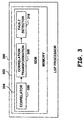
- Fig. 3 is a simplified block diagram illustrating a LGF processor 300 according to an exemplary embodiment of the present invention.
- the LGF processor 300 may, for example, be implemented in the DGPS Cabinet 204 of the LGF 200 shown in Fig. 2 .
- the LGF processor 300 includes a memory 302 having a signal deformation monitor (SDM) 304 stored thereon.
- the SDM 304 may, for example, consist of a series of machine instructions operable to assist in monitoring signal deformation.
- the memory 302 is shown as being "on-board," (i.e. part of the LGF processor 300) the memory may instead be located in a physically separate location from the LGF processor 300, with a means for connecting the memory and the LGF processor 300.
- the SDM 304 of the exemplary embodiment is a software module, other implementation schemes may alternatively be used, such as a firmware or hardware implementation. The software scheme described herein provides the most flexibility.
- the SDM 304 may include a correlator 306, a correlation transformation 308, and a fault detector 310.
- the correlator 306 may determine a plurality of correlation measurements at points along a correlation curve. The correlation curve is further described with reference to Fig. 4 . Each correlation measurement may be based upon a correlation between a received satellite signal and a reference.
- An exemplary correlator 306 is described in U. S. Patent Application No. 09/691, 690 ; however, any combination of hardware, firmware, and software may be used to perform the correlation between the received satellite signal and the reference.
- the correlation transformation 308 may subtract the mean of the correlation measurements over all tracked satellites from each of the correlation measurements.
- the correlation transformation 308 may be performed using any combination of hardware, firmware, and software. Since all selected satellite signals pass through the front end of the same receiver 208, any variations in the front end may be canceled. By canceling out the variations, front end signal deformation may not bias the correlation measurements determined by the correlator 306. Additional details regarding the correlation transformation 308 are described with reference to Fig. 5 .
- the fault detector 310 may determine the differences between the correlation measurements and the correlation curve and detect signal distortion based on the magnitudes of the differences. Additionally or alternatively, the fault detector 310 may calculate a plurality of differential measurements by determining the difference in value between a pair of correlation measurements. The plurality of differential measurements may then be compared to expected values of the measurements. The expected values are the differential values expected if there was no satellite signal deformation. This comparison may be used to detect signal deformation.
- An exemplary fault detector 310 is described in U.S. Patent Application No. 09/691,690 ; however, any combination of hardware, firmware, and software operable to determine the differences between the correlation measurements along the correlation curve may be used to detect signal deformation.
- Fig. 4 is a simplified correlation curve 400, according to an exemplary embodiment of the present invention.
- the correlation curve 400 may be realized by correlating code received from a satellite with a plurality of code references that are time shifted replicas of the code transmitted by the same satellite.
- the correlator 306 may perform this correlation.
- the correlation curve 400 illustrates code offset in chips, with a maximum correlation of 1.00 occurring at the correlation peak 402 (point P).
- the correlation peak 402 occurs where a reference code has a zero time shift with respect to the received code. This measurement is referred to as being "punctual.”
- the in-phase measurements e.g. point M 1
- the in-phase measurements represent the amount of correlation between the received code and reference codes that have predetermined time shifts that make the reference code early with respect to the received code. These measurements are referred to as being "early.”
- the in-phase measurements e.g. points M 2 -M 6
- the in-phase measurements represent the amount of correlation between the received code and reference codes that have predetermined time shifts that make the reference code late with respect to the received code. These measurements are referred to as being "late.”
- the correlation measurements of Fig. 4 may be obtained when Doppler is tracked (i.e. quadrature measurements are driven to zero).
- the internal code replicas may be positioned at different offsets ⁇ n to ⁇ K relative to the received signal code.
- the resulting in-phase measurements are averaged over an interval T and are low-pass filtered. Other implementations may also be used.
- the fault detector 310 within SDM 304 determines whether the signal deformation threshold has been reached.
- Fig. 5 is a correlation diagram 500 illustrating a typical front end deformation 502 of the correlation peak 504.
- the front end correlation peak deformation may be the same for all received satellite signals. Therefore, it may be possible to define a correlation measurement f ⁇ k that is independent of this common deformation.
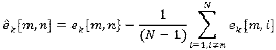
- the front end independent correlation measurement may be calculated by subtracting the mean over all selected satellites from each of the correlation measurements.
- the correlation transformation 308 in the SDM 304 may perform this calculation.
- the fault detector 310 in the SDM 304 may calculate a plurality of differential measurements by determining the difference in value between a pair of correlation measurements. The plurality of differential measurements may then be compared to expected values of these measurements. This comparison may be used to detect signal deformation.
- both the correlation measurements and the differential measurements are converted to front end independent entities based on the same algorithm.
- a satellite with a favorable signal-to-noise ratio relative to other satellites may be degraded more than this, but the advantage of removing a bias that is about 3 times the 1-sigma performance is likely to outweigh this drawback for most applications. If a satellite is degraded so that its presence is unfavorable, it may be deselected as the conversion is performed. Accurate results may be obtained if all noise-induced biases are removed before these new measurements are formed.
- the transformed correlation and differential measurements may be used to form SDM monitor discriminators that optimize the visibility of the signal deformations that pose a threat and must be detected.
- U.S. Patent Application No. 09/691,690 sets forth methods and apparatus for forming these discriminators and provides additional details on correlation and signal distortion detection.
- a reliable signal deformation monitor may be constructed that is independent of deformations occurring at the receiver front end.
Landscapes
- Engineering & Computer Science (AREA)
- Radar, Positioning & Navigation (AREA)
- Remote Sensing (AREA)
- Computer Networks & Wireless Communication (AREA)
- Physics & Mathematics (AREA)
- General Physics & Mathematics (AREA)
- Position Fixing By Use Of Radio Waves (AREA)
Claims (6)
- System zum Überwachen einer Satellitensignaldeformation, das in Kombination Folgendes umfasst:einen Korrelator (306), der dafür ausgelegt ist, mehrere Korrelationsmessungen für jeden von mehreren Satelliten an Punkten entlang einer Korrelationskurve (400) zu bestimmen, wobei jede Korrelationsmessung auf einer Korrelation zwischen einem empfangenen Satellitensignal und einer Referenz basiert;eine Korrelationstransformation (308), die dafür ausgelegt ist, einen Mittelwert der Korrelationsmessungen über die mehreren Satelliten von jeder der mehreren Korrelationsmessungen zu subtrahieren, wodurch eine Verzerrung infolge einer Front-End-Signaldeformation aus den mehreren Korrelationsmessungen entfernt wird; undeinen Fehlerdetektor (310), der dafür ausgelegt ist, einen Diskriminator auf der Basis mehrerer Differenzen zwischen den mehreren Korrelationsmessungen und der Korrelationskurve (400) zu bestimmen und eine Signaldeformation anhand dessen zu detektieren, ob eine Signaldeformationsschwelle erreicht wurde.
- System nach Anspruch 1, wobei die mehreren Korrelationsmessungen gemäß der folgenden Gleichung berechnet werden:

- System nach Anspruch 2, wobei die Standardabweichung der mehreren Korrelationsmessungen gemäß der folgenden Gleichung berechnet wird:

- System nach Anspruch 1, wobei der Fehlerdetektor (310) dafür ausgelegt ist, eine Differenzialmessung durch Bestimmen einer Differenz zwischen einem Paar Korrelationsmessungen zu berechnen.
- System nach Anspruch 4, wobei die Differenzialmessung gemäß der folgenden Gleichung berechnet wird:
- System nach Anspruch 5, wobei die Standardabweichung der Differenzialmessung gemäß der folgenden Gleichung berechnet wird:

Applications Claiming Priority (9)
| Application Number | Priority Date | Filing Date | Title |
|---|---|---|---|
| US41308002P | 2002-09-24 | 2002-09-24 | |
| US41321102P | 2002-09-24 | 2002-09-24 | |
| US41325202P | 2002-09-24 | 2002-09-24 | |
| US41325102P | 2002-09-24 | 2002-09-24 | |
| US413211P | 2002-09-24 | ||
| US413252P | 2002-09-24 | ||
| US413251P | 2002-09-24 | ||
| US413080P | 2003-09-22 | ||
| PCT/US2003/029955 WO2004031799A1 (en) | 2002-09-24 | 2003-09-24 | Signal deformation monitor |
Publications (2)
| Publication Number | Publication Date |
|---|---|
| EP1570288A1 EP1570288A1 (de) | 2005-09-07 |
| EP1570288B1 true EP1570288B1 (de) | 2016-10-19 |
Family
ID=34753885
Family Applications (3)
| Application Number | Title | Priority Date | Filing Date |
|---|---|---|---|
| EP03755852.5A Expired - Lifetime EP1570288B1 (de) | 2002-09-24 | 2003-09-24 | Signaldeformationsmonitor |
| EP03755853.3A Expired - Lifetime EP1570286B1 (de) | 2002-09-24 | 2003-09-24 | Radiofrequenzinterferenzmonitor |
| EP03770399.8A Expired - Lifetime EP1573354B1 (de) | 2002-09-24 | 2003-09-24 | Niedrigleistungsentdeckung und -kompensation für satellitensystemen |
Family Applications After (2)
| Application Number | Title | Priority Date | Filing Date |
|---|---|---|---|
| EP03755853.3A Expired - Lifetime EP1570286B1 (de) | 2002-09-24 | 2003-09-24 | Radiofrequenzinterferenzmonitor |
| EP03770399.8A Expired - Lifetime EP1573354B1 (de) | 2002-09-24 | 2003-09-24 | Niedrigleistungsentdeckung und -kompensation für satellitensystemen |
Country Status (1)
| Country | Link |
|---|---|
| EP (3) | EP1570288B1 (de) |
Families Citing this family (3)
| Publication number | Priority date | Publication date | Assignee | Title |
|---|---|---|---|---|
| CN112596078A (zh) * | 2020-12-19 | 2021-04-02 | 中国电波传播研究所(中国电子科技集团公司第二十二研究所) | 一种基于载噪比统计的卫星导航欺骗干扰检测方法 |
| WO2023023912A1 (zh) * | 2021-08-23 | 2023-03-02 | 华为技术有限公司 | 一种节点间测距的方法及装置 |
| CN114826360B (zh) * | 2022-04-28 | 2024-10-11 | 上海航天测控通信研究所 | 一种用于分集接收的环路失锁解决方法及系统 |
Citations (1)
| Publication number | Priority date | Publication date | Assignee | Title |
|---|---|---|---|---|
| EP0535570A1 (de) * | 1991-10-01 | 1993-04-07 | Rockwell International Corporation | Verarbeitung transienter Detektion, insbesondere Erkennung akustischer Signale unter Wasser |
Family Cites Families (1)
| Publication number | Priority date | Publication date | Assignee | Title |
|---|---|---|---|---|
| US6331835B1 (en) * | 1999-02-02 | 2001-12-18 | The Charles Stark Draper Laboratory, Inc. | Deeply-integrated adaptive GPS-based navigator with extended-range code tracking |
-
2003
- 2003-09-24 EP EP03755852.5A patent/EP1570288B1/de not_active Expired - Lifetime
- 2003-09-24 EP EP03755853.3A patent/EP1570286B1/de not_active Expired - Lifetime
- 2003-09-24 EP EP03770399.8A patent/EP1573354B1/de not_active Expired - Lifetime
Patent Citations (1)
| Publication number | Priority date | Publication date | Assignee | Title |
|---|---|---|---|---|
| EP0535570A1 (de) * | 1991-10-01 | 1993-04-07 | Rockwell International Corporation | Verarbeitung transienter Detektion, insbesondere Erkennung akustischer Signale unter Wasser |
Also Published As
| Publication number | Publication date |
|---|---|
| EP1573354A2 (de) | 2005-09-14 |
| EP1570286B1 (de) | 2018-08-08 |
| EP1573354B1 (de) | 2017-01-25 |
| EP1570288A1 (de) | 2005-09-07 |
| EP1570286A1 (de) | 2005-09-07 |
Similar Documents
| Publication | Publication Date | Title |
|---|---|---|
| US6667713B2 (en) | Self-monitoring satellite system | |
| EP0776484B1 (de) | Differentielles gps bodenstationsystem | |
| US7555262B2 (en) | Radio frequency interference monitor | |
| EP1328823B1 (de) | Verfahren und vorrichtung zur schätzung der geschwindigkeit eines endgerätes in einem drahtlosen kommunikationssystem | |
| EP0776483B1 (de) | Fail-safe differentielles gps bodenstationsystem | |
| RU2621827C2 (ru) | Бортовая система содействия пилотированию летательного аппарата, основанная на системе gnss, имеющая избыточную и несходную архитектуру для повышенного уровня достоверности | |
| US5438337A (en) | Navigation system using re-transmitted GPS | |
| US9513376B1 (en) | Low-cost high integrity integrated multi-sensor precision navigation system | |
| US6311127B1 (en) | Satellite navigation system having redundant signal processing and matched filtering | |
| JP2000512018A (ja) | 衛星位置決定システムのためのスプーフィング検出システム | |
| EP2434313A2 (de) | Verfahren zur Verschmelzung mehrerer GPS-Messungsarten in eine gewichtete Kleinstquadratlösung | |
| US11921223B2 (en) | System and method for detecting spoofing of global navigation satellite system signals using a plurality of antennas | |
| EP2081042A2 (de) | Navigationssystem mit Vorrichtung zur Detektion von Genauigkeitsfehlern | |
| EP3869233A1 (de) | Detektion und abschwächung von gnss-korrelationsverzerrung | |
| US6888498B2 (en) | Method and system for compensating satellite signals | |
| WO2004031799A1 (en) | Signal deformation monitor | |
| US20020118133A1 (en) | System and method for computing navigation information in the presence of interference | |
| US6809684B2 (en) | Signal deformation monitor | |
| US20240027631A1 (en) | Mac method for monitoring, with common bias compensation, the integrity of a point positioning process using virtual beacons | |
| EP1570288B1 (de) | Signaldeformationsmonitor | |
| EP1554598B1 (de) | Validierung von bakensignalen | |
| US7423585B2 (en) | Navigation signal group delay calibration | |
| EP1970723A1 (de) | Verfahren zur Berechnung verbesserter SBAS-Schutzebenen, die für nicht gesteuerte Umgebungen gelten | |
| US6172638B1 (en) | Satellite signal receiver with detector of incoherence between code phase and carrier frequency measurements | |
| CN116540268B (zh) | 一种机载定位完好性监测方法及装置 |
Legal Events
| Date | Code | Title | Description |
|---|---|---|---|
| PUAI | Public reference made under article 153(3) epc to a published international application that has entered the european phase |
Free format text: ORIGINAL CODE: 0009012 |
|
| 17P | Request for examination filed |
Effective date: 20050425 |
|
| AK | Designated contracting states |
Kind code of ref document: A1 Designated state(s): AT BE BG CH CY CZ DE DK EE ES FI FR GB GR HU IE IT LI LU MC NL PT RO SE SI SK TR |
|
| AX | Request for extension of the european patent |
Extension state: AL LT LV MK |
|
| DAX | Request for extension of the european patent (deleted) | ||
| RBV | Designated contracting states (corrected) |
Designated state(s): FR |
|
| REG | Reference to a national code |
Ref country code: DE Ref legal event code: 8566 |
|
| 17Q | First examination report despatched |
Effective date: 20131218 |
|
| RAP1 | Party data changed (applicant data changed or rights of an application transferred) |
Owner name: HONEYWELL INTERNATIONAL INC. |
|
| GRAP | Despatch of communication of intention to grant a patent |
Free format text: ORIGINAL CODE: EPIDOSNIGR1 |
|
| RIC1 | Information provided on ipc code assigned before grant |
Ipc: G01S 19/21 20100101AFI20160415BHEP Ipc: G01S 19/23 20100101ALN20160415BHEP Ipc: G01S 19/01 20100101ALN20160415BHEP |
|
| RIC1 | Information provided on ipc code assigned before grant |
Ipc: G01S 19/01 20100101ALN20160428BHEP Ipc: G01S 19/21 20100101AFI20160428BHEP Ipc: G01S 19/23 20100101ALN20160428BHEP |
|
| INTG | Intention to grant announced |
Effective date: 20160524 |
|
| GRAS | Grant fee paid |
Free format text: ORIGINAL CODE: EPIDOSNIGR3 |
|
| GRAA | (expected) grant |
Free format text: ORIGINAL CODE: 0009210 |
|
| AK | Designated contracting states |
Kind code of ref document: B1 Designated state(s): FR |
|
| PLBE | No opposition filed within time limit |
Free format text: ORIGINAL CODE: 0009261 |
|
| STAA | Information on the status of an ep patent application or granted ep patent |
Free format text: STATUS: NO OPPOSITION FILED WITHIN TIME LIMIT |
|
| 26N | No opposition filed |
Effective date: 20170720 |
|
| REG | Reference to a national code |
Ref country code: FR Ref legal event code: PLFP Year of fee payment: 15 |
|
| REG | Reference to a national code |
Ref country code: FR Ref legal event code: PLFP Year of fee payment: 16 |
|
| PGFP | Annual fee paid to national office [announced via postgrant information from national office to epo] |
Ref country code: FR Payment date: 20180927 Year of fee payment: 16 |
|
| PG25 | Lapsed in a contracting state [announced via postgrant information from national office to epo] |
Ref country code: FR Free format text: LAPSE BECAUSE OF NON-PAYMENT OF DUE FEES Effective date: 20190930 |
|
| P01 | Opt-out of the competence of the unified patent court (upc) registered |
Effective date: 20230525 |