EP1569464A2 - Optische Anordnung mit nicht invertierender Beleuchtungsvorrichtung - Google Patents
Optische Anordnung mit nicht invertierender Beleuchtungsvorrichtung Download PDFInfo
- Publication number
- EP1569464A2 EP1569464A2 EP05003034A EP05003034A EP1569464A2 EP 1569464 A2 EP1569464 A2 EP 1569464A2 EP 05003034 A EP05003034 A EP 05003034A EP 05003034 A EP05003034 A EP 05003034A EP 1569464 A2 EP1569464 A2 EP 1569464A2
- Authority
- EP
- European Patent Office
- Prior art keywords
- colour
- light
- sub
- beams
- modulating means
- Prior art date
- Legal status (The legal status is an assumption and is not a legal conclusion. Google has not performed a legal analysis and makes no representation as to the accuracy of the status listed.)
- Withdrawn
Links
Images


Classifications
-
- H—ELECTRICITY
- H04—ELECTRIC COMMUNICATION TECHNIQUE
- H04N—PICTORIAL COMMUNICATION, e.g. TELEVISION
- H04N9/00—Details of colour television systems
- H04N9/12—Picture reproducers
- H04N9/31—Projection devices for colour picture display, e.g. using electronic spatial light modulators [ESLM]
- H04N9/3102—Projection devices for colour picture display, e.g. using electronic spatial light modulators [ESLM] using two-dimensional electronic spatial light modulators
- H04N9/3105—Projection devices for colour picture display, e.g. using electronic spatial light modulators [ESLM] using two-dimensional electronic spatial light modulators for displaying all colours simultaneously, e.g. by using two or more electronic spatial light modulators
-
- H—ELECTRICITY
- H04—ELECTRIC COMMUNICATION TECHNIQUE
- H04N—PICTORIAL COMMUNICATION, e.g. TELEVISION
- H04N9/00—Details of colour television systems
- H04N9/12—Picture reproducers
- H04N9/31—Projection devices for colour picture display, e.g. using electronic spatial light modulators [ESLM]
- H04N9/3141—Constructional details thereof
- H04N9/317—Convergence or focusing systems
Definitions
- the present invention relates to an optical system and methods of operating the same for a projection system. More specifically the present invention relates to an optical system and method of operating the same for a color projection system having a good throughput efficiency and good color uniformity.
- Large-screen, high-brightness electronic projection display apparatuses serve different broad areas of application: electronic presentations for e.g. business, education and advertising, entertainment for e.g. home theatre and electronic cinema, display of status and information for e.g. military, utilities and transportation, simulation in e.g. training and games. In all these areas the need to correctly display color images is large.
- a spatial light modulator unit comprises at least one spatial light modulator, which is a device that modulates incident light in a spatial pattern corresponding to an electrical or optical input.
- the spatial light modulator is a pixelated device, i.e. an array of pixel display elements, wherein each pixel or group of pixels can be addressed and driven independently to project or display an arbitrary image.
- the spatial light modulator can modulate incident light in its phase, intensity, polarisation, or direction, and the light modulation may be achieved by a variety of materials exhibiting various electro-optic or magneto-optic effects or by materials that modulate light by surface deformation.
- An SLM comprises a one- or two-dimensional array of light-modulating elements. Silicon technology used in projection data monitors is capable of producing small-sized, two-dimensional light-valve arrays having several hundred thousand to several million light-modulating elements.
- Spatial light modulators are either transmissive or reflective. Transmissive devices modulate the light beam as it passes through the unit. Reflective devices modulate the light as it reflects from a mirror inside the unit.
- Typical examples of SLM devices are a deformable mirror device (DMD), also called digital mirror device or digital micromirror device, a reflective LCD device, an LCOS device, etc.
- a single imager spatial colour filter design whereby each pixel is divided into three colour sub-pixels
- a single imager colour field sequential system whereby the beam is sequentially filtered to each primary colour which is then modulated in the single imager
- a two, three or multi-imager parallel colour system whereby the light beam is split into two, three or more primary colours, each colour beam is directed to an imager and the modulated colour beams are converged into a single beam for projection.
- An X-cube is a dichroic prism which allows to split the white light of the light source into three primary colours and/or to recombine the three primary colours to one illumination beam for projection.
- either light of different sources having a different wavelength or wavelength range can be used, or, what is more common, the light of a white light source is used and split into a number, typically three, basic colours or colour ranges. Very often these correspond with the three primary colours red, green and blue.
- the optics used to split the light of a white light source will play an important role and should be designed carefully. Not only are the sizes of the projection screens continuously increasing, so that small errors in colour projection become relatively more important, the human eye is also very sensitive to colour differences. Therefore, it is an essential feature to obtain colour projection as optimal as possible. This includes both a high contrast and a good colour homogeneity, i.e. a reduced colour shift.
- One way to improve the colour uniformity and homogeneity is providing equal path lengths for the different colours. This allows uniform magnifications of the illumination pattern for each of the three colour channels. If illumination patterns with generally the same intensity uniformity profiles are formed and these are superposed, this allows improved uniformity of the colour image.
- US 6,532,044 describes an electronic projector combining multiple projection lens assemblies with equal colour component optical path lengths to provide improved display images and a compact arrangement.
- the document discusses the use of separate projection lens assemblies for each of the basic colours which are arranged in a non-linear, close-packed arrangement to receive the different colour components of light.
- the arrangement does not comprise an X-cube but has different dichroic mirrors. Therefore, equal path lengths can be obtained using mirrors and dichroic mirrors, as suggested in US 6,532,044. Nevertheless, as no convergence of the different colour beams is performed, the system is relatively complex compared to conventional three imager parallel colour systems.
- Three projection lens assemblies are provided, which makes the quality for colour imaging strongly dependent of the quality and outlining of the different projection assemblies.
- DE4313139 describes a projection system having a metal halide lamp emitting light in its three primary colours by a system of filters and mirrors.
- the system is built such that the three optical paths from the source to the LCD panels are all equal in length.
- the advantage of the system is that there is an improved projection by providing a shorter distance between the focus and the rear of the projection lens and that fewer dichroic mirrors are needed in the colour synthesizer. Nevertheless, the system does not include an X-cube. This leads to additional problems with colour shift and light intensity of the different colours in the illumination beam as after modulation the different colour beams need to pass different and a different number of dichroic mirrors in order to form one single illumination beam.
- EP 0 458 687 describes a system having a large degree of compactness and a good resolution power.
- the system is based on a mirror system whereby each of the primary colours is modulated by a light modulating means.
- This system also does not comprise an X-cube and therefore recombination of the different colour beams needs to be performed by different dichroic mirrors, leading to additional problems with colour shift and light intensity of the different colours.
- a colour projection system for projecting an image on a screen comprising at least one light source for emitting a light beam, e.g. a white light beam, and a light splitting means for splitting the emitted light beam into colour sub-beams.
- Each sub-beam comprises light of a different wavelength or wavelength range.
- the colour projection system furthermore comprises, for each of the colour sub-beams, a light modulating means and a dichroic prism for recombining the colour sub-beams.
- Each of said modulating means is positioned adjacent to a side of the dichroic prism.
- the colour projection system furthermore comprises further optical components for imaging each of the colour sub-beams onto its light modulating means such that the images of each of the colour sub-beams on the corresponding light modulating means have a substantial equal size and such that the images of each of the colour sub-beams on the screen have the same orientation.
- the images of each of the colour sub-beams may have a substantial equal size which may be such that differences between the size of the images of each of the colour sub-beams on the corresponding light modulating means are preferably smaller than 5%, more preferably smaller than 1 %, most preferably smaller than 0.5%.
- the colour projection system furthermore may be adjusted such that the light path from at least one light source to behind the dichroic prism is situated in one plane.
- the dichroic prism may be an X-cube.
- the colour projection system may be such that for an image representing a plane of equal colour, the distance between the average colour coordinates in the 1976 CIE Chromaticity Diagram for the ANSI-points at the left side of the image on the screen and for the ANSI-points at the right side of the image on the screen is preferably smaller than 0.01, more preferably smaller than 0.007, most preferably smaller than 0.005. This distance is measured in the 1976 CIE Chromaticity Diagram.
- the ANSI points are defined as the points that are at the centre of the rectangles created by dividing an image on a screen into 9 equal rectangles. The rectangles do not overlap but cover the whole image.
- the optical components of the colour projection system furthermore may comprise a first imaging lens, whereby for each colour sub-beam the light path length between the first imaging lens and the light modulating means is preferably equal within 1%, more preferably equal within 0.1 %, most preferably equal within 0.01%. This means that the difference in length may, preferably, not be larger than 1%, more preferably not larger than 0.1 %, most preferably not larger than 0.01%.
- the first imaging lens is the imaging lens which is closest in the light path to the light source or light sources.
- the light splitting means may comprise at least a first light splitting device for splitting the emitted, e.g. white, beam in a first colour beam comprising light of a first wavelength or wavelength region and a further colour beam, whereby the first light splitting device may be positioned in the pupil of the first imaging lens.
- a first light splitting device for splitting the emitted, e.g. white, beam in a first colour beam comprising light of a first wavelength or wavelength region and a further colour beam, whereby the first light splitting device may be positioned in the pupil of the first imaging lens.
- the first light splitting device may be a dichroic mirror.
- the dichroic mirror may have a small incidence angle dependency.
- the dichroic mirror in the colour projection system may be transmitting a first part of the light beam and reflecting a second part of the light beam and may have, preferably, a 50% transmission point whereby 50% of the light beam is transmitted, wherein the small incidence angle dependency is such that the difference for the wavelength at which the 50% transmission point of the dichroic mirror is positioned for different angles of incidence, may be preferably smaller than 25 nm, more preferably smaller than 17 nm, most preferably smaller than 7 nm.
- the further optical components furthermore may comprise colour filters.
- the optical components also may comprise a further number of imaging lenses positioned in the light paths of the different colour sub-beams, wherein either for each colour sub-beam, the number of imaging lenses is even or for each colour sub-beam the number of imaging lenses is odd.
- the light modulating means may be transmissive light modulating means and the colour projection system may not comprise a mirror between the transmissive light modulating means and the dichroic prism.
- the optical components of the colour projection system furthermore may comprise a number of mirrors positioned in the light paths of the different colour sub-beams, wherein either for each colour sub-beam the number of mirrors is even or for each colour sub-beam the number of mirrors is odd.
- the invention also relates to a method for projecting a colour image, comprising the steps of driving one or more light sources to create a light beam, e.g. a white light beam, splitting said emitted light beam in colour sub-beams, each comprising light of a different wavelength or wavelength region, imaging each of said colour sub-beams on a light modulating means, positioned adjacent to a side of a dichroic prism, modulating each of said colour sub-beams by said light modulating means and recombining said modulated colour sub-beams in said dichroic prism and projecting said recombined light beam.
- a light beam e.g. a white light beam
- splitting said emitted light beam in colour sub-beams each comprising light of a different wavelength or wavelength region
- each of said colour sub-beams on a light modulating means thereby is performed such that the image on the light modulating means has equal size for each of said colour sub-beams and such that the image on the screen has equal orientation for each of said colour sub-beams.
- said imaging may be performed such that the light paths between a first imaging lens, being the image lens positioned closest in the light path to the at least one light source and the light modulating means for each of the colour sub-beams are preferably equal in length within 1%, more preferably equal within 0, 1 %, most preferably equal within 0,01 %.
- the optical recombination system is based on an X-cube, thereby avoiding or at least reducing the use of mirrors on the light paths downstream the light modulating means and thus avoiding strong influences of small errors in flatness which may occur in the mirrors. It is a specific advantage of the present invention that the colour beams are combined in a single optical component, thereby reducing the chance of errors introduced by shift of multiple optical components with respect to each other.
- the image on the light valve has an equal magnification and has an equal sign of magnification, i.e. that either none of the colour images is inverted or all of the colour images are inverted.
- the teachings of the present invention permit the design of improved methods and apparatus for optical systems for projection systems.
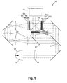
- Fig. 1 shows an optical system for a colour projection system according to an embodiment of the present invention.
- the present invention relates particularly to the colour splitting and recombination system of a projector system, and it is not expected that the invention is limited by the integrating method.
- the optical system i.e. the colour splitting and recombination system, as proposed in any of the embodiments of the present invention can be used with light tunnels, with light guides, with light rods, with integrator lenses or any other integrating method.
- the optical system 50 comprises one or more light sources 52 which may be any light generating device, e.g. a metal halide lamp or an LED array.
- the light source 52 also may include a parabolic or elliptic reflector 53 to optimally reflect the back projected light from the light source 52.
- the optical systems furthermore may comprise lenses and mirrors.
- the lenses typically are made of optical glass and may have an anti-reflective coating on both sides. Other types of lens materials may be used such as quartz, but these are less preferable as these are more expensive.
- dichroic mirrors typically are made of standard glass, such as float glass, and comprise coatings which e.g. reflect a first set of colours and transmit the remaining colours. These dichroic mirrors can e.g. be obtained from the company UNAXIS, for example.
- the dichroic mirrors furthermore may comprise standard anti-reflective coatings.
- the light beam coming from the light source 52 is imaged using one imaging lens 54 onto spatial light modulating means for the different colours, i.e. a first light modulating means 56a for a first colour e.g. blue, a second light modulating means 56b for a second colour e.g. green and a third light modulating means 56c for a third colour e.g. red.
- the light beam is split in a plurality of sub-beams having different colours, e.g. three sub-beams. This is performed using any suitable colour splitting device, e.g. dichroic mirrors 58 and 60 allowing certain colours to pass through the mirror, whereas other colours are reflected.
- the light modulating system 62a, 62b, 62c used can comprise any type of light modulating means 56a, 56b, 56c.
- the light modulating means 56a, 56b, 56c can be any of a transmissive liquid crystal display device, an LCOS device a deformable mirror device (DMD), also called digital mirror device or digital micromirror device, a reflective LCD device, or any other suitable light modulating means.
- DMD deformable mirror device
- the light modulating system 62a, 62b, 62c also may comprise a lens 64a, 64b, 64c, a polarizer 66a, 66b, 66c and an analyzer 68a, 68b, 68c, ....
- the optical system will be described using a transmissive LCD device as a light modulating means 56a, 56b, 56c.
- the polarizers 66a, 66b, 66c and analyzers 68a, 68b, 68c can be standard optical components, as may e.g. be obtained from the company Polatechno, for example.
- the light modulating means 56a, 56b, 56c act as imagers, i.e. they modulate the different colour sub-beams such that for each of these colours an arbitrary image is created.
- the light modulating means 56a, 56b, 56c comprise an array of light modulating elements.
- the light modulating elements can be addressed and driven such as to display an arbitrary image. After this modulation, the different sub-beams are converged in a single beam using an X-cube 70.
- An X-cube is typically made of optical glass and has anti-reflective coatings on all sides of the X-cube.
- the X-cube 70 allows recombining the different colour sub-beams into one light beam which is directed to a projection lens 72 to project the image, consisting of the plurality, e.g. three, colour sub-images, onto a screen (not shown in Fig. 1).
- an X-cube 70 is used having an s-p-s polarization, meaning that the X-cube 70 is optimised for receiving the red and the blue colour sub-beam having a first polarization, i.e. the s-polarization, an receiving the green sub-beam having a second polarization, i.e. the p-polarization.
- the analyzers 68a, 68b, 68c are adjusted to obtain the correct polarization for the colour sub-beams in the present example.
- the invention is not limited to the use of an s-p-s-polarization X-cube, other X-cubes also can be used.
- the projector system combines compactness, i.e. whereby the light system has a light path that is situated in one plane, and an optimized colour uniformity, i.e. whereby the image of the different colour beams all have the same size on the light modulating means 56a, 56b, 56c and all have the same orientation, i.e. that the magnification for each of the colour light beams is the same on the light modulating means 56a, 56b, 56c.
- the term "the same magnification” means that both the size of each of the images is the same and the sign of the magnification is the same. This can be achieved by optimizing the position and the number of lenses in each of the light beams and colour light sub-beams.
- the lens system used in the light system for the projection system is designed such that the size of the colour images and the orientation of the colour images on the light modulating means are substantially equal for all different colours.
- the differences between the sizes of the different colour images are preferably smaller than 5%, more preferably smaller than 1 %, most preferably smaller than 0.5%.
- Obtaining the same orientation for all colour images on the screen means that there either has to be an odd number of imaging lenses for each of the colour images on the light modulating means 56a, 56b, 56c or that an even number of imaging lenses has to be provided for each of the colour images on the light modulating means 56a, 56b, 56c, i.e. in each of the colour sub-beam paths of the light system.
- a second one-to-one imaging system is provided, such that the image in the colour light path comprising the one-to-one imaging systems is doubly inverted.
- the number of mirrors is either odd for all colour light sub-beams or even for all colour light sub-beams, such that no differently mirrored colour images on the screen are obtained. It is to be noted that the mirror inside the X-cube should also be taken into account for counting the total number of mirrors for each light sub-beam.
- FIG.1 An illustration of such a system is shown in Fig.1 whereby, in order to obtain an equal magnification for all different colour light paths additional lenses are added in one colour light path.
- a light beam from a light source 52 is directed to an imaging lens 54 and then directed to a dichroic mirror 58 to split the light beam into a blue and a yellow sub-beam.
- the blue light sub-beam is directed onto a light modulating system 62a whereby an image is generated in the blue light sub-beam.
- the yellow sub-beam is directed onto a second dichroic mirror 60 so as to split it into a green and a red sub-beam and the green sub-beam is directed onto a light modulating system 62b, whereby an image is generated in the green light sub-beam.
- the remaining part of the yellow sub-beam i.e. the red sub-beam, is directed onto a light modulating system 62c, whereby an image is generated in the red light sub-beam.
- the blue, green and red sub-beams are recombined in an X-cube 70, whereafter the recombined beam is directed to a projection lens 72 to be projected onto a screen.
- the light path of the red sub-beam is significantly longer than the light paths of the other sub-beams. Therefore, in order to obtain the same magnification, a lens system is provided in the longer light path.
- a double one-to-one imaging is performed in the red sub-beam in sequence using a double set of additional lenses 74. In this way the red colour image is inverted twice and therefore, no or less discoloration will be visible.
- the current embodiment has the advantage that each of the light modulating means 56a, 56b, 56c can be positioned close to the X-cube 70, thus providing a very short light path between each of the light modulating means 56a, 56b, 56c and the X-cube 70. In these cases, no additional mirror is necessary to guide the light beams from the light modulating means 56a, 56b, 56c to the X-cube 70.
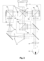
- Fig. 2. shows an alternative example of the present embodiment, showing the same components as the previous example, but wherein the light modulating system 62a, 62b, 62c is based on reflective spatial light modulating means 56a, 56b, 56c that are not positioned directly in the vicinity of the X-cube 70.
- the light in the different light paths is first directed to the light modulating means 56a, 56b, 56c by reflection on a mirror 76a, 76b, 76c making an angle of 45° with the light modulating means 56a, 56b, 56c, then modulated by driving the light modulating means 56a, 56b, 56c and subsequently directed towards the X-cube 70 through the mirror 76a, 76b, 76c.
- an X-cube 70 is used having an s-p-s polarization, meaning that the X-cube 70 is optimised for receiving the red and the blue colour sub-beam having a first polarization, i.e. the s-polarization, and receiving the green sub-beam having a second polarization, i.e. the p-polarization.
- a half wavelength plate 78 is provided in the light paths of both the red and the blue sub-beam.
- the present example again illustrates that additional optical components are used to obtain a substantially equal magnification, i.e.
- the three colour sub-images 80, 84, 88 are shown, furthermore showing a small area 82, 86, 90 with a higher brightness, corresponding with a spot having a higher brightness in the illumination beam.
- the colour sub-image 80 is inverted.
- the sub-images 80, 84, 88 correspond with settings of the light modulating means 56a, 56b, 56c such as to obtain a homogeneous colour. For the system not inverting or inverting the colour sub-images an even number of times (left hand side of Fig.
- the combination of the three colour sub-images 80, 84, 88 leads to a full colour image 92 with an area 94 having an increased brightness but not having colour inhomogeneities, whereas for the system inverting one of the colour sub-image an odd number of times (right hand side of Fig. 3), the combination of the three colour sub-images 80, 84, 88 leads to a full colour image 92 showing a first area 96 and a second area 98 having not only a different brightness, but also a difference in colour for both area 96 and area 98.
- a mirrored image of one of the coloured images is created with respect to the other coloured images.
- Any brightness non-uniformity in the object thus causes a colour non-uniformity in the image on the screen.
- the human eye is very sensitive to colour non-uniformity and thus, a brightness non-uniformity in the object is seen as a discoloration.
- a non-uniformity in the object causes a brightness non-uniformity on the screen image.
- the human eye is less sensitive to brightness non-uniformities, this significantly reduces the problem.
- a measure for representing colour differences is the shift in the CIE 1976 U.C.S. Chromaticity Diagram, as defined by the "Commission Internationale de l'Eclairage” (CIE) in 1976.
- CIE Commission Internationale de l'Eclairage
- the distance between the colour coordinates in the u'v' colour diagram for a point at the left side of the image and a point at the right side of the image is discussed, for an image that in principle should have the same colour coordinates for all points of the image, i.e. an image whereby all points of the image should have a colour corresponding with the same point in the colour diagram, for all points of the image.
- the distance corresponds directly with a visual colour difference.
- ⁇ u'v' thus means that the colour coordinates of a point left and right on the screen are positioned closer together, so that the colour difference between the two point is appearing smaller for the human eye.
- Table 1 shows values for the left-right colour shift for a conventional system and the left-right colour shift for a system having a double inverted colour image for one of the different colours.
- the average shift in the colour diagram typically is about 0.013
- the colour shift is reduced to 0.0045.
- This colour shift is measured according to the following procedure. The image on the screen is divided in 9 rectangles, which do not overlap and fill the image on the screen completely. The centres of these rectangles define the 9 ANSI-points (American National Standard Institute). These 9 ANSI points are typically used to define characteristics of a display.
- the colour shift is measured by measuring the x and y CIE 1976 colour coordinates, which can be converted to u' and v' CIE 1976, averaging the u' and v' values for the 3 ANSI points at the left side of the image and for the 3 ANSI points at the right side of the image and determining the distance in the CIE 1976 U.C.S. Chromaticity Diagram between the average u' and v' values for the left ANSI points and the average u' and v' values for the right ANSI points.
- the human eye can see colour differences that are separated 0.004 in the u'v' colour diagram.
- the external conditions play an important role, i.e. the amount of stray light present from the environment, the brightness of the image and even the status of the person looking at the image, i.e. whether this person is tired, what the quality of the eyes of the viewer is, etc.
- Fig. 4 a schematic representation of an optical system for a projection system 100 according to a second embodiment of the present invention is shown.
- the projection system comprises a light source 52, a number of optical components, a number of light modulating means 56a, 56b, 56c for forming an image for a corresponding number of colour sub-beams which are created, an X-cube 70 for recombining the colour sub-beams and a projection lens 72 for projecting the images on a screen (not represented in Fig. 4).
- the images of the colour sub-beams projected onto the light modulating means 56a, 56b, 56c have the same magnification and the same orientation.
- the differences in magnification between the sizes of the different colour images are preferably smaller than 5%, more preferably smaller than 1%, most preferably smaller than 0.5%. In this embodiment, this is performed by providing equal light paths for all colour sub-beams. With equal light paths, it is meant that the distances between the imaging lens or imaging lenses 104, 112 and the light modulating means 56a, 56b, 56c are preferably equal, for all colours, within 5%, more preferably within 1%, most preferably within 0.1%.
- the light source 52 used for generating the light beam may be any light generating device, such as e.g. a metal halide lamp or an array of LEDs.
- the light source may have a parabolic shaped or elliptic shaped reflector 53 to optimally direct the light out of the light source 52.
- the position of the different light modulating means 56a, 56b, 56c can be changed in order to obtain equal light paths for all colours, this is not possible for systems using an X-cube 70. Therefore, if the system comprises an X-cube 70 for recombining the colour sub-beams and if the light modulating means 56a, 56b, 56c are positioned near this X-cube 70, a specific optical setup is needed.
- a compact optical system whereby the light path is completely situated in one plane and whereby equal light path lengths for all colours are provided, can only be made if light splitting means 102 are provided near the pupil of the imaging lens(es) 104, 112, preferably at the pupil of the imaging lens(es) 104, 112. Positioning the light splitting means 102 at the pupil of the imaging lens(es) 104, 112 is preferred as by placing the light splitting means 102 not exactly at the pupil, the angles of incidence are increased, leading either to loss of light as more light needs to be cut away out of the spectrum or to more discoloration. It is not obvious to position the light splitting means 102 at the pupil of the imaging lens(es) 104, 112.
- the light splitting means 102 typically is a dichroic mirror which suffers from incident angle dependent colour shift. The latter cannot be corrected using a gradient filter, which is the standard solution to solve for angle dependency if the dichroic mirror is placed away from the pupil of the imaging lens(es) 104, 112. Therefore, in the current embodiment, the light splitting means 102 should be selected specifically such that the angle dependency of the dichroic mirror is minimal.
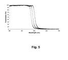
- Fig. 5 shows a graph of the transmission of a dichroic mirror as a function of the wavelength for different angles of incidence.
- the dichroic mirror substantially blocks a first part of the white light, transmits a second part of the white light and shows a transition area.
- the 50% transmission point i.e. the wavelength at which the transmission for the light is 50%, is strongly angle of incidence dependent.
- the graph shows the 50% transmission point for an angle of incidence (AOI) of 45° (triangle), an angle of incidence (AOI) of 40° (cross) and an angle of incidence (AOI) of 35° (square). It can be seen that the angle dependency for this dichroic mirror is limited, i.e.
- Fig. 5 also illustrates that the colour shift angle dependency of the dichroic mirror cannot be reduced completely by an optimised selection of the dichroic mirror, i.e. there always will remain some angle dependency.
- further means may be provided to filter unwanted light from the different colour sub-beams.
- FIG. 4 A layout for an optical system according to this embodiment is shown in Fig. 4.
- the light beam is directed to a light splitting means 102 to split the light beam in different colour components.
- typically three colour sub-beams are used, which may be but is not limited to the primary colours red, green and blue. These colours typically are defined by the wavelength of the emitted light or the wavelength region wherein the wavelength of the emitted light is situated.
- red, green and blue sub-beam typically is defined by the wavelength of the emitted light or the wavelength region wherein the wavelength of the emitted light is situated.
- the light splitting means 102 splits the light beam into different coloured sub-beams, i.e. a first sub-beam comprising light of a first colour, in this example red, and a second sub-beam comprising light of the remaining colours, in this example green and blue.
- a first sub-beam comprising light of a first colour, in this example red
- a second sub-beam comprising light of the remaining colours, in this example green and blue.
- the first splitting of the light beam is performed in the pupil plane of the imaging lens with telecentric illumination. This allows to obtain equal light paths for the different colour sub-beams in a compact setup of the projection system. The latter leads to colour sub-images having an equal size on the light modulating means 56a, 56b, 56c, thereby reducing the colour shift.
- additional optical components are used, which can be lenses and/or mirrors.
- the lenses typically are made of optical glass and have standard anti-reflecting coatings on both sides.
- the lenses also can be made of other material, e.g. quartz, but optical glass is preferred as this material is less expensive.
- the mirrors typically are made of float glass and have standard reflecting coatings on one side. Such coatings can e.g. be obtained from the company UNAXIS.
- dichroic mirrors are used, typically made of float glass and comprising a dichroic reflecting coating, e.g.
- the light splitting means 102 typically is a dichroic mirror, which in the present example transmits red light into a first light path, while cyan light is reflected on a second light path.
- the red light sub-beam is focussed by an imaging lens 104 on the light modulating means 56c corresponding with the red light sub-beam.
- the mirrors 106, 108, 110 direct the red light sub-beam onto a light modulating system which comprises a light modulating means 56c and, depending on the type of light modulating means 56c used, furthermore may comprise a lens 64c, a polarizer 66c and an analyser 68c.
- a light modulating system which comprises a light modulating means 56c and, depending on the type of light modulating means 56c used, furthermore may comprise a lens 64c, a polarizer 66c and an analyser 68c.
- the latter components have been discussed with respect to a previous embodiment of the invention, and are introduced if e.g. the light modulating means 56c are a transmissive LCD panel.
- the light modulating system can have any or all of the characteristics described with respect to the light modulating systems used in other embodiments.
- light from in the second light path will be imaged on the light modulating means 56b, 56c by an imaging lens 112 and directed by a mirror 113 on a dichroic mirror 114 for splitting the cyan sub-beam into a green sub-beam and a blue sub-beam.
- the green sub-beam is then directed onto a further mirror 116 and finally onto a light modulating system, which comprises a light modulating means 56b and furthermore may comprise a lens 64b, and a polarizer 66b and analyzer 68b depending on the light modulating means used 56b.
- the light modulating system can have any or all of the characteristics described with respect to the light modulating systems used in other embodiments.
- the blue light sub-beam is directed on the light modulating system using a further mirror 118.
- the light modulating system comprises a light modulating means 56a, and furthermore may comprise a lens 64a and a polarizer 66a and analyzer 68a depending on the light modulating means used.
- the light modulating means can have any or all of the characteristics described with respect to the light modulating means used in other embodiments.
- the first sub-beam and the second sub-beam may include some colour-shifted light. Therefore it is a specific feature of this embodiment to provide additional colour filters. These colour filters are positioned in the light path of two colour sub-beams. These two colour sub-beams are the sub-beams corresponding with the colour that is first separated from the other colours in the pupil plane and with the neighbouring colour, i.e. the colour which is closest to the first separated colour in the wavelength spectrum. In the present example, the colour filters thus will be positioned in the light path of the red and the green sub-beam.
- These colour filters also can be dichroic mirrors, made of standard glass, such as float glass, and comprising a coating to filter specific colours, as can e.g. be obtained from the company UNAXIS.
- the colour filters are introduced by replacing the mirrors in the different light paths with dichroic mirrors. In this way it is possible to filter out the yellow light generated by colour shift due to incidence angle dependency.
- a mercury lamp is used, in this way also the yellow mercury spectral line is removed, which is an additional advantage of the system.
- the sub-beams are recombined using an X-cube 70. The recombined light beam will be projected on a screen by a projection lens 72.
- the discoloration i.e. the inhomogeneity in colour or colour shifts
- the discoloration i.e. the inhomogeneity in colour or colour shifts
- the discoloration on the screen also can be reduced further by taking into account the number of mirrors that are used for each of the colour beams.
- the colour inhomogeneities can be further reduced if the number of mirroring parts for each of the colours is all even or all odd.
- the mirror in the X-cube has to be taken into account.
- the distance between the colour coordinates of a point left and a point right of an image that in principle displays one colour, i.e. the image left-right colour shift, for a system providing equal path lengths according to the present embodiment of the invention, is 0.0064. This is less than half the left-right colour shift of a conventional system (0.013). This is also shown in Table 1.
- the current embodiment has the additional advantage that each of the light modulating means 56a, 56b, 56c can be positioned close to the X-cube 70, thus providing a very short light path between each of the light modulating means 56a, 56b, 56c and the X-cube 70. In these cases, no additional mirror is necessary to guide the light colour sub-beams from the light modulating means to the X-cube.
- Fig. 6 shows another example of the current embodiment wherein an equal path length system with reflective light modulating means 56a, 56b, 56c is shown.
- the colour projection system has the same components as the previous example, but the light modulating system 62a, 62b, 62c now is based on reflective light modulating means 56a, 56b, 56c that are not positioned directly in the vicinity of the X-cube 70.
- the light in the different light paths is first directed to the light modulating means 56a, 56b, 56c by reflection on a mirror 76a, 76b, 76c making an angle of 45° with the light modulating means 56a, 56b, 56c, then modulated by driving the light modulating means 56a, 56b, 56c and subsequently directed towards the X-cube 70 through the mirror 76a, 76b, 76c.
- Half wavelength plates 78 are provided to obtain the correct polarization of the colour sub-beams for use with an s-p-s X-cube 70.
- the current example of the present embodiment is less optimum and less compact, it still has the advantage of providing substantially equal path lengths for the different colour beams between the imaging lens(es) 104, 112 which is (are) closest in the light path to the light source 52 or light sources and the light modulating means 56a, 56b, 56c, i.e. the path lengths do not differ more than 1%, preferably do not differ more than 0.1%, more preferably do not differ more than 0.01 %.
- the light path from the light source or light sources till behind the dichroic prism, e.g. the X-cube is situated in one plane. It is furthermore a specific advantage of the embodiments of the present invention that the systems are compact. Furthermore it is a specific advantage of the embodiments of the present invention that the size of the different colour images on the light modulating means are substantially equal in size and have the same orientation.
Landscapes
- Engineering & Computer Science (AREA)
- Multimedia (AREA)
- Signal Processing (AREA)
- Projection Apparatus (AREA)
- Video Image Reproduction Devices For Color Tv Systems (AREA)
Applications Claiming Priority (2)
| Application Number | Priority Date | Filing Date | Title |
|---|---|---|---|
| US10/785,249 US7192141B2 (en) | 2004-02-24 | 2004-02-24 | Optical arrangement for non-inverting illumination system |
| US785249 | 2004-02-24 |
Publications (2)
| Publication Number | Publication Date |
|---|---|
| EP1569464A2 true EP1569464A2 (de) | 2005-08-31 |
| EP1569464A3 EP1569464A3 (de) | 2007-10-03 |
Family
ID=34750466
Family Applications (1)
| Application Number | Title | Priority Date | Filing Date |
|---|---|---|---|
| EP05003034A Withdrawn EP1569464A3 (de) | 2004-02-24 | 2005-02-14 | Optische Anordnung mit nicht invertierender Beleuchtungsvorrichtung |
Country Status (2)
| Country | Link |
|---|---|
| US (1) | US7192141B2 (de) |
| EP (1) | EP1569464A3 (de) |
Cited By (2)
| Publication number | Priority date | Publication date | Assignee | Title |
|---|---|---|---|---|
| US11029592B2 (en) | 2018-11-20 | 2021-06-08 | Flightsafety International Inc. | Rear projection simulator with freeform fold mirror |
| US11122243B2 (en) | 2018-11-19 | 2021-09-14 | Flightsafety International Inc. | Method and apparatus for remapping pixel locations |
Families Citing this family (11)
| Publication number | Priority date | Publication date | Assignee | Title |
|---|---|---|---|---|
| JP4652112B2 (ja) * | 2005-04-26 | 2011-03-16 | 富士フイルム株式会社 | 投射型表示装置 |
| US7641350B2 (en) * | 2005-11-28 | 2010-01-05 | Jds Uniphase Corporation | Front surface mirror for providing white color uniformity for polarized systems with a large range of incidence angles |
| JP2008209888A (ja) * | 2007-01-31 | 2008-09-11 | Sony Corp | 光学装置および投射型表示装置 |
| ITRM20070183A1 (it) * | 2007-04-03 | 2008-10-04 | Optikon 2000 Spa | Apparato oftalmologico multifunzione. |
| US20110108042A1 (en) * | 2009-11-10 | 2011-05-12 | Philip Morris Usa Inc. | Registered banded cigarette paper, cigarettes, and method of manufacture |
| TW201232149A (en) * | 2011-01-21 | 2012-08-01 | Delta Electronics Inc | Light system for projection device and projection device comprising the same |
| US20130044120A1 (en) * | 2011-08-19 | 2013-02-21 | Apple Inc. | Thermal color shift reduction in lcds |
| US8970740B2 (en) * | 2012-12-14 | 2015-03-03 | In View Technology Corporation | Overlap patterns and image stitching for multiple-detector compressive-sensing camera |
| TWI448659B (zh) * | 2012-12-27 | 2014-08-11 | Metal Ind Res & Dev Ct | Optical image capture module, alignment method and observation method |
| US11378810B2 (en) | 2018-03-20 | 2022-07-05 | Arizona Board Of Regents On Behalf Of The University Of Arizona | Polygon x-prism for imaging and display applications |
| CN112799272B (zh) * | 2019-11-13 | 2023-09-15 | 深圳光峰科技股份有限公司 | 显示设备及其控制方法 |
Family Cites Families (12)
| Publication number | Priority date | Publication date | Assignee | Title |
|---|---|---|---|---|
| EP1063554B1 (de) * | 1994-12-28 | 2004-03-03 | Seiko Epson Corporation | Polarisations-Beleuchtungsvorrichtung und diese verwendender Projektor |
| JP2738331B2 (ja) * | 1995-03-16 | 1998-04-08 | 日本電気株式会社 | 投射型液晶表示装置 |
| JP3631296B2 (ja) * | 1995-04-04 | 2005-03-23 | 三菱電機株式会社 | 画像生成装置 |
| JP3290091B2 (ja) * | 1997-03-31 | 2002-06-10 | シャープ株式会社 | 投影型画像表示装置 |
| JPH11212022A (ja) * | 1998-01-28 | 1999-08-06 | Nec Corp | 映像投射装置 |
| US6467911B1 (en) * | 1998-10-08 | 2002-10-22 | Minolta Co., Ltd. | Projector and lamp unit |
| JP3622556B2 (ja) * | 1999-02-23 | 2005-02-23 | セイコーエプソン株式会社 | 照明光学系および投写型表示装置 |
| JP2001154151A (ja) * | 1999-11-25 | 2001-06-08 | Minolta Co Ltd | 照明光学系及びそれを用いた液晶プロジェクタ |
| KR100374532B1 (ko) * | 2000-04-19 | 2003-03-04 | 정의신 | 인터넷 검색시 광고 방법 |
| JP2002090878A (ja) * | 2000-09-20 | 2002-03-27 | Seiko Epson Corp | プロジェクタ |
| JP3802502B2 (ja) * | 2002-03-28 | 2006-07-26 | 三洋電機株式会社 | 投写型映像表示装置 |
| US6807020B2 (en) * | 2002-08-01 | 2004-10-19 | Jenmar Visual Systems | Lens optimization and color correction for image projection systems |
-
2004
- 2004-02-24 US US10/785,249 patent/US7192141B2/en not_active Expired - Lifetime
-
2005
- 2005-02-14 EP EP05003034A patent/EP1569464A3/de not_active Withdrawn
Cited By (6)
| Publication number | Priority date | Publication date | Assignee | Title |
|---|---|---|---|---|
| US11122243B2 (en) | 2018-11-19 | 2021-09-14 | Flightsafety International Inc. | Method and apparatus for remapping pixel locations |
| US11595626B2 (en) | 2018-11-19 | 2023-02-28 | Flightsafety International Inc. | Method and apparatus for remapping pixel locations |
| US11812202B2 (en) | 2018-11-19 | 2023-11-07 | Flightsafety International Inc. | Method and apparatus for remapping pixel locations |
| US12192686B2 (en) | 2018-11-19 | 2025-01-07 | Flightsafety International Inc. | Method and apparatus for remapping pixel locations |
| US11029592B2 (en) | 2018-11-20 | 2021-06-08 | Flightsafety International Inc. | Rear projection simulator with freeform fold mirror |
| US11709418B2 (en) | 2018-11-20 | 2023-07-25 | Flightsafety International Inc. | Rear projection simulator with freeform fold mirror |
Also Published As
| Publication number | Publication date |
|---|---|
| US7192141B2 (en) | 2007-03-20 |
| US20050185143A1 (en) | 2005-08-25 |
| EP1569464A3 (de) | 2007-10-03 |
Similar Documents
| Publication | Publication Date | Title |
|---|---|---|
| US8979272B2 (en) | Multi-primary color display | |
| US7929193B2 (en) | Multi-primary color projection display | |
| US5555035A (en) | Very high resolution light valve writing system based on tilting lower resolution flat panels | |
| US10678061B2 (en) | Low etendue illumination | |
| KR20120023627A (ko) | 고 동적 범위 투사 시스템 | |
| JP2006154834A (ja) | 画像を表示するための表示システムおよび方法 | |
| US7192141B2 (en) | Optical arrangement for non-inverting illumination system | |
| US6919990B2 (en) | Methods and systems for low loss separation and combination of light | |
| US6665122B1 (en) | Projection-type image display apparatus | |
| CN108345160B (zh) | 一种投影显示系统 | |
| WO2020088163A1 (zh) | 投影系统及投影控制方法 | |
| US10104352B2 (en) | Projector and image display method | |
| EP4155818A1 (de) | Anzeigesystem | |
| KR20050084151A (ko) | 마이크로디스플레이용 동적 범위 및 콘트라스트 향상 | |
| US7494225B2 (en) | Projector including an illumination device with a light cut-off member and rotating prism | |
| KR100822505B1 (ko) | 화상 표시 장치 및 프로젝터 | |
| JP2002214706A (ja) | 画像表示用照明装置、投射型表示装置及び画像表示方法 | |
| US12038679B2 (en) | Wavelength conversion apparatus, light source system and display device | |
| Roelandt et al. | Color uniformity in compact LED illumination for DMD projectors | |
| US12204237B2 (en) | Image display apparatus and image display unit | |
| CN111352287A (zh) | 光源系统及投影设备 | |
| WO2005094070A1 (en) | Dual liquid crystal on silicon (lcos) to digital light pulse (dlp) relay | |
| EP1463336A2 (de) | Projektionsvorrichtung und Verfahren zum Übertragen von Licht in einem Projektionsgerät | |
| JP4543680B2 (ja) | 照明光学系 | |
| JP2008532056A (ja) | 小型投射ディスプレイ |
Legal Events
| Date | Code | Title | Description |
|---|---|---|---|
| PUAI | Public reference made under article 153(3) epc to a published international application that has entered the european phase |
Free format text: ORIGINAL CODE: 0009012 |
|
| AK | Designated contracting states |
Kind code of ref document: A2 Designated state(s): AT BE BG CH CY CZ DE DK EE ES FI FR GB GR HU IE IS IT LI LT LU MC NL PL PT RO SE SI SK TR |
|
| AX | Request for extension of the european patent |
Extension state: AL BA HR LV MK YU |
|
| RIN1 | Information on inventor provided before grant (corrected) |
Inventor name: DE MEERLEER, PETER Inventor name: VAN BELLE, KOEN Inventor name: VAN DEN BOSSCHE, BART Inventor name: BEYERS, KOEN Inventor name: HALSBERGHE, BRECHT |
|
| PUAL | Search report despatched |
Free format text: ORIGINAL CODE: 0009013 |
|
| AK | Designated contracting states |
Kind code of ref document: A3 Designated state(s): AT BE BG CH CY CZ DE DK EE ES FI FR GB GR HU IE IS IT LI LT LU MC NL PL PT RO SE SI SK TR |
|
| AX | Request for extension of the european patent |
Extension state: AL BA HR LV MK YU |
|
| 17P | Request for examination filed |
Effective date: 20080403 |
|
| AKX | Designation fees paid |
Designated state(s): AT BE BG CH CY CZ DE DK EE ES FI FR GB GR HU IE IS IT LI LT LU MC NL PL PT RO SE SI SK TR |
|
| 17Q | First examination report despatched |
Effective date: 20090402 |
|
| STAA | Information on the status of an ep patent application or granted ep patent |
Free format text: STATUS: THE APPLICATION IS DEEMED TO BE WITHDRAWN |
|
| 18D | Application deemed to be withdrawn |
Effective date: 20091013 |