EP1569407B1 - Computer system for allocating storage area to a computer based on a security level - Google Patents
Computer system for allocating storage area to a computer based on a security level Download PDFInfo
- Publication number
- EP1569407B1 EP1569407B1 EP04009222A EP04009222A EP1569407B1 EP 1569407 B1 EP1569407 B1 EP 1569407B1 EP 04009222 A EP04009222 A EP 04009222A EP 04009222 A EP04009222 A EP 04009222A EP 1569407 B1 EP1569407 B1 EP 1569407B1
- Authority
- EP
- European Patent Office
- Prior art keywords
- computer
- information
- storage system
- volume
- server
- Prior art date
- Legal status (The legal status is an assumption and is not a legal conclusion. Google has not performed a legal analysis and makes no representation as to the accuracy of the status listed.)
- Expired - Fee Related
Links
Images


Classifications
-
- H—ELECTRICITY
- H04—ELECTRIC COMMUNICATION TECHNIQUE
- H04L—TRANSMISSION OF DIGITAL INFORMATION, e.g. TELEGRAPHIC COMMUNICATION
- H04L63/00—Network architectures or network communication protocols for network security
- H04L63/04—Network architectures or network communication protocols for network security for providing a confidential data exchange among entities communicating through data packet networks
- H04L63/0428—Network architectures or network communication protocols for network security for providing a confidential data exchange among entities communicating through data packet networks wherein the data content is protected, e.g. by encrypting or encapsulating the payload
-
- H—ELECTRICITY
- H04—ELECTRIC COMMUNICATION TECHNIQUE
- H04L—TRANSMISSION OF DIGITAL INFORMATION, e.g. TELEGRAPHIC COMMUNICATION
- H04L67/00—Network arrangements or protocols for supporting network services or applications
- H04L67/01—Protocols
- H04L67/10—Protocols in which an application is distributed across nodes in the network
- H04L67/1097—Protocols in which an application is distributed across nodes in the network for distributed storage of data in networks, e.g. transport arrangements for network file system [NFS], storage area networks [SAN] or network attached storage [NAS]
-
- H—ELECTRICITY
- H04—ELECTRIC COMMUNICATION TECHNIQUE
- H04L—TRANSMISSION OF DIGITAL INFORMATION, e.g. TELEGRAPHIC COMMUNICATION
- H04L9/00—Cryptographic mechanisms or cryptographic arrangements for secret or secure communications; Network security protocols
- H04L9/40—Network security protocols
-
- H—ELECTRICITY
- H04—ELECTRIC COMMUNICATION TECHNIQUE
- H04L—TRANSMISSION OF DIGITAL INFORMATION, e.g. TELEGRAPHIC COMMUNICATION
- H04L67/00—Network arrangements or protocols for supporting network services or applications
- H04L67/2866—Architectures; Arrangements
- H04L67/288—Distributed intermediate devices, i.e. intermediate devices for interaction with other intermediate devices on the same level
-
- H—ELECTRICITY
- H04—ELECTRIC COMMUNICATION TECHNIQUE
- H04L—TRANSMISSION OF DIGITAL INFORMATION, e.g. TELEGRAPHIC COMMUNICATION
- H04L69/00—Network arrangements, protocols or services independent of the application payload and not provided for in the other groups of this subclass
- H04L69/30—Definitions, standards or architectural aspects of layered protocol stacks
- H04L69/32—Architecture of open systems interconnection [OSI] 7-layer type protocol stacks, e.g. the interfaces between the data link level and the physical level
- H04L69/322—Intralayer communication protocols among peer entities or protocol data unit [PDU] definitions
- H04L69/329—Intralayer communication protocols among peer entities or protocol data unit [PDU] definitions in the application layer [OSI layer 7]
-
- Y—GENERAL TAGGING OF NEW TECHNOLOGICAL DEVELOPMENTS; GENERAL TAGGING OF CROSS-SECTIONAL TECHNOLOGIES SPANNING OVER SEVERAL SECTIONS OF THE IPC; TECHNICAL SUBJECTS COVERED BY FORMER USPC CROSS-REFERENCE ART COLLECTIONS [XRACs] AND DIGESTS
- Y10—TECHNICAL SUBJECTS COVERED BY FORMER USPC
- Y10S—TECHNICAL SUBJECTS COVERED BY FORMER USPC CROSS-REFERENCE ART COLLECTIONS [XRACs] AND DIGESTS
- Y10S707/00—Data processing: database and file management or data structures
- Y10S707/953—Organization of data
- Y10S707/959—Network
-
- Y—GENERAL TAGGING OF NEW TECHNOLOGICAL DEVELOPMENTS; GENERAL TAGGING OF CROSS-SECTIONAL TECHNOLOGIES SPANNING OVER SEVERAL SECTIONS OF THE IPC; TECHNICAL SUBJECTS COVERED BY FORMER USPC CROSS-REFERENCE ART COLLECTIONS [XRACs] AND DIGESTS
- Y10—TECHNICAL SUBJECTS COVERED BY FORMER USPC
- Y10S—TECHNICAL SUBJECTS COVERED BY FORMER USPC CROSS-REFERENCE ART COLLECTIONS [XRACs] AND DIGESTS
- Y10S707/00—Data processing: database and file management or data structures
- Y10S707/99931—Database or file accessing
- Y10S707/99939—Privileged access
-
- Y—GENERAL TAGGING OF NEW TECHNOLOGICAL DEVELOPMENTS; GENERAL TAGGING OF CROSS-SECTIONAL TECHNOLOGIES SPANNING OVER SEVERAL SECTIONS OF THE IPC; TECHNICAL SUBJECTS COVERED BY FORMER USPC CROSS-REFERENCE ART COLLECTIONS [XRACs] AND DIGESTS
- Y10—TECHNICAL SUBJECTS COVERED BY FORMER USPC
- Y10S—TECHNICAL SUBJECTS COVERED BY FORMER USPC CROSS-REFERENCE ART COLLECTIONS [XRACs] AND DIGESTS
- Y10S707/00—Data processing: database and file management or data structures
- Y10S707/99951—File or database maintenance
- Y10S707/99956—File allocation
Definitions
- the present invention relates to a storage area management method in a storage area network (hereinafter, "IP-SAN") for establishing a connection among a plurality of computers and storage systems over the Internet Protocol (IP) network.
- IP Internet Protocol
- the SAN is a network used for establishing a connection among a plurality of storage systems and computers.
- Fibre Channel Protocol is often used for data transfer over the SAN.
- FC-SAN Fibre Channel Protocol
- iSCSI is a protocol used for transmitting and receiving SCSI commands and data over the IP network.
- the SCSI commands are those conventionally used for communications between computers and storage systems, and the data is the one to be transferred based on those commands.
- iSCSI authored by Julian Satran, et al., January 19, 2003, IETF, ⁇ URL: http://www.ietf.org/internet-drafts/draft-ietf-ips-iscsi-2 0.txt>.
- the IP-SAN has such an advantage that any existing LAN (Local Area Network) equipment that is already in use as infrastructure can be used therewith, for example.
- LAN Local Area Network
- IP-SAN requires much consideration for security. This is because, unlike the FC-SAN, a network used for the IP-SAN may not always be secure enough, e.g., the Internet, and intracorporate LAN. Further, it is common knowledge that attack methods and attack programs have been developed specifically for the IP network.
- zoning for partitioning a communications path using switches or fabrics
- LUN masking Logical Unit Number masking
- the IPSec may be used to encrypt the communications path between computers and storage systems.
- the IPSec refer to "Security Architecture for IP” authored by Stephen Kent and Randall Arkinson, November 1998, IETF, ⁇ URL: http://www.ietf.org/rfc/rfc2401.txt>.
- the IPSec is a technique of encrypting a communications path using a shared key.
- IKE Internet Key Exchange
- IP-SAN devices to be connected to the IP-SAN are not all necessarily equipped with means for security protection as above.
- some devices to be connected to the IP-SAN may be implemented with IPSec but some may not, and security protection is not necessarily always required for communications between computers and storage systems.
- system managers are required to always pay attention to matters such as whether devices connected to a network have a safeguard for security protection, and the security level of system components. While paying attention as such, the system managers need to allocate storage systems connected to the network and their storage areas to computers also connected to the network. This problematically puts an enormous burden on the system managers. What is more, once such allocation settings are made by the system managers, computer users find it difficult to freely change the settings of storage area allocation. Further, the security level setting for communications between the computers and the storage systems may be unnecessarily high, resulting in a waste of system resources.
- US 2002/0174306 A1 discloses virtual storage exchange system (VSX) that provides the storage device to a host computer using storage mapping rules.
- VSX virtual storage exchange system
- US 2003/0225801 Al disclose storage attributes that are device related including capacity, bandwidth, I/O rates, sequential/direct, reliability/error rates, concurrent copy capability, physical location, security, lease duration, cost, etc.
- An embodiment is directed to a system including a computer for managing information about computers and storage systems to be connected to a network.
- a computer for managing information about computers and storage systems to be connected to a network.
- the network management server selects any of the storage systems that is satisfying predetermined requirements, and then instructs the storage system to create a storage area.
- the storage system accordingly creates a storage area following the predetermined requirements, and after completion, forwards a creation completion notice to the network management server.
- the network management server After receiving the notice, the network management server notifies the computers of information for using thus created storage area, e.g., network address assigned to a port of the storage system. Based on such information, the computers use the created storage area.
- information for using thus created storage area e.g., network address assigned to a port of the storage system.
- the information about the storage systems and others managed by the network management server is information about the security level.
- the request coming from the computers may also include a request about the security level. If this is the case, the network management server may search its own information for any storage system meeting the security level requested by the computers. The resulting storage system is then instructed to create a storage area.
- the security level may be information indicating whether or not an encryption process is executable in the devices for data transmission and reception.
- FIG. 1 is a diagram showing an exemplary system structure of a first embodiment.
- the system includes: a computer (in the below, referred also to as “server”) 101; a storage system 102; and a network management server (in the below, referred also to as “management server”) 103.
- the server and the storage system are connected to each other over an IP network 104.
- a control network 105 connects among the server, the storage system, and the management server.
- the system exemplarily shown in FIG. 1 has the IP network 104 and the control network 105 are each independent network. Alternatively, these networks may be shared as a single network.
- the server 101 and the storage system 102 to be connected to the IP network 104 are both arbitrary in number.
- the server 101 performs data transmission and reception with the storage system 102 over the IP network 104.
- the IP network 104 is the one over which IP packets can be transferred.
- IP network includes Ethernet LANs, Ethernet WANs (Wide Area Network), and wide area IP networks, lease lines, and others provided by local exchange carriers.
- the management server 103 performs transmission and reception of management information with the server 101 and the storage system 102 over the control network 105.
- the server 101 is a general computer, and provided with a processor (in the below, referred also to as "CPU") 106, memory 107, and a host bus adapter (in the below, referred also to as "HBA") 108.
- the CPU 106, the memory 107, and the HBA 108 are connected together via a bus 109.
- the memory stores a path management program 110, a disk path management table 111, and a password management table 112.
- these programs are stored in the memory 107, for example, of the server 101 via a portable storage device or over a network.
- the processor 106 determines a data communications path between the server 101 and the storage system 102 over the IP network 104. This determination is made based on information stored in the disk path management table 111 about paths between the server and the storage system. The processor 106 uses information coming from managers, users, other programs, and the like, as a basis for determining or changing the data communications path.
- the path information stored in the disk path management table 111 is used by the server 101 to make access to the storage system 102 connected to the IP network 104.
- the disk path management table 111 also stores path property information, e. g. , whether the path is provided with the encryption property using IPSec.
- the HBA 108 is connection equipment used for establishing a connection between the server 101 and the IP network 104.
- the HBA 108 has an Interface chip (hereinafter, referred also to as "IF chip") 113, a physical port 115 for connection to the IP network 104, and an IPSec processing unit 127.
- IF chip Interface chip
- the physical port 115 is always used for data transfer between the server 101 and the IP network 104.
- the IF chip 113 is a circuit for exercising control over a packet process for packet transmission and reception to/from the IP network 104, e.g. , SCSI command encapsulation, and DMA (Direct Memory Access) transfer between the physical port 115 and the memory 107 of the server 101, and others.
- SCSI command encapsulation e.g., SCSI command encapsulation
- DMA Direct Memory Access
- the IPSec processing unit 127 is a processor for going through processes of data encryption and decryption before communications, cryptographic key exchange and authentication between devices, for example. Prior to authentication, the IPSec processing unit 127 searches the password management table 112 stored in the memory 107 for a password needed for authentication of the device on the other end.
- HBA 108 in the present embodiment is assumed to execute processes required for encrypted transfer using IPSec.
- the issue here is that the HBA 108 of the server 101 may not always be capable of going through the IPSec process. Accordingly, for distinction hereinafter, the HBA 108 capable of going through the IPSec process is referred to as HBA 108a, and the one not capable of going through the IPSec process is referred to as HBA 108b.
- the storage system 102 is provided with host adapters 120a and 120b, a CPU 116, a disk adapter 117, memory 119, cache memory 118, and disk device group 121.
- a bus 122 establishes a connection among the host adapters 120a and 120b, the CPU 116, the disk adapter 117, the memory 119, and the cache memory 118. Instead of such a bus 122, a switch is an alternative option.
- the disk adapter 117 connects together the disk device group 121 and the bus 122.
- the memory 119 stores a volume information table 123, and a password management table 124.
- the CPU 116 makes access to the memory 119 via the bus 122 to execute a program stored in the memory 119.
- the disk adapter 117 exercises access control over the CPU 116 with respect to the disk device group 121.
- the cache memory 118 temporarily stores data to be transferred to the server 101 or data coming therefrom.
- the disk device group 121 includes one or more of a disk device.
- the disk device group 121 may plurally include volatile memory such as a flash memory card.
- Each disk device has a physical storage area. From such a physical storage area belonging to each corresponding disk device, the storage system 102 creates a logical storage area (in the below, referred to as "physical volume"). Using the physical volume as a unit, the storage system 102 handles its own storage area as a single logical storage.
- the disk device group structuring the physical volume may be in the RAID structure.
- the storage system 102 creates a volume from one or more physical volumes.
- the volume is a unit of the logical storage area that is provided to the server 101, and is equivalent to a logical unit (LU) used with the SCSI protocol, for example.
- LU logical unit
- the host adapters 120 each include a physical port 125 that is to be connected to the IP network 104.
- the host adapter 120a also includes the IPSec processing unit 127 for executing a process needed for encrypted transfer using IPSec.
- the storage system 102 includes, one each, the host adapter 120a that executes a process for encrypted transfer using IPSec, and the host adapter 120b that does not execute such a process.
- the number of the host adapters 120 is not surely restrictive, and the storage system 102 may include the arbitrary number of the host adopters 120a and 120b, respectively.
- the storage system 102 may include either the host adapter 102a or 102b.
- the volume information table 123 stores information that shows the interrelation between physical volumes and volumes. To be specific, stored therein are a volume number corresponding to a specific physical volume (hereinafter, referred to as logical unit number (LUN), a volume capacity, and identifier (ID) information (e.g., address) of the physical port 115 assigned to the volume. Every time a volume is newly created, the storage system 102 updates the contents of the volume information table 123.
- LUN logical unit number
- ID identifier
- the password management table 124 stores a password needed for authentication under IKE when the host adapter 120a of the storage system 102 executes the IPSec process.
- the management server 103 is a general computer, and includes a processor (in the below, referred also to as "CPU") 128, memory 129, and a network adapter 130.
- a bus 131 establishes a connection among the CPU 128, the memory 129, and the network adapter 130 .
- the memory 129 stores a network management program 132, and a network configuration database 133.
- the network configuration database 133 includes a port attribute table 134, and a storage capacity management table 135.
- the port attribute table 134 information is registered for the management server 103 to manage the physical port connected to the IP network 104.
- registered are a node identifier (ID) for uniquely distinguishing a device having the physical port, an address for any other devices to access the physical port, and information about whether an HBA or a host adapter having the physical port can execute the IPSec process.
- ID node identifier
- the storage capacity management table 1335 information is registered for the management server 103 to manage the storage capacity of the storage system 102 connected to the IP network 104.
- the information indicates the still-available capacity (hereinafter, "unused capacity") of the storage area and the already-used capacity thereof (hereinafter, “capacity of used area” or “used capacity”) in the respective storage systems 102 connected to the IP network 104.
- unused capacity still-available capacity
- capacity of used area hereinafter, "used capacity”
- the processor 128 of the management server 103 executes the network management program 132 for information collection via the control network 105.
- the information is the one about the physical ports located in the server 101 and the storage system 102, and the one about the unused capacity and the used capacity in the storage. Then, based on thus collected information, the management server 103 creates or updates the port attribute table 134 and the storage capacity management table 135.
- the management server 103 When a volume creation request comes from the server 101, the system manager, or the like, the management server 103 responsively makes a search of the contents of the port attribute table 134 and the storage capacity management table 135. After the search, another request for creating a volume satisfying the requirements is issued with respect to the storage system 102. Further, after receiving a volume creation completion notice from the storage system 102, the management server 103 notifies completion of volume creation to the server 101, the manager, or others. Herein, the server 101 or the system manager is the one having issued the volume creation request. Then, the management server 103 collects passwords needed for authentication at the time of IKE, and issues a command for the server 101 and the storage system 102 to register any newly input password with the password management tables 112 and 117 .
- FIG. 2 is a diagram showing an exemplary structure of the port attribute table 134, which stores property information about the physical ports 115 and 125 (hereinafter, referred to as collectively “physical port 115 and others” or simply “physical port”) connected to the IP network 104.
- the port attribute table 134 has entries corresponding in number to the physical ports 115 and others connected to the IP network 104. Each entry includes fields 201 to 207. Specifically, the field 201 is registered with a node ID for identifying which device includes the physical port 115 and others corresponding to the entry; the field 202 is registered with an object identifier (ID) of an SCSI object assigned to the corresponding physical port 115 and others; the field 203 is registered with an IP address assigned to the corresponding physical port 115 and others; the field 204 is registered with a node type that is information for distinguishing which device has the corresponding physical port 115 and others, i.e.
- ID object identifier
- the server 101 or the storage system 102 the field 205 is registered with information indicating whether the HBA 108 or the host adapter 120 having the corresponding physical port 115 and others includes an IPSec processing unit; the field 206 is registered with an authentication identifier (ID); and the field 207 is registered with a password.
- ID authentication identifier
- assignment of an SCSI object to a physical port means that the server 101 determines which physical port to use when using an SCSI object. Accordingly, once determined, the server 101 is not allowed to use an SCSI object using any other physical port.
- the object ID is an SCSI object identifier that is defined by SAM (SCSI Architecture Model).
- SAM Serial Bus Architecture Model
- the SCSI object is a generic term for a device from which an SCSI command is issued (logically or physically: hereinafter, "SCSI initiator"), and a device that receives the SCSI command (logically or physically: hereinafter, "SCSI target”).
- the object ID is equivalent to an iSCSI name with iSCSI, and WWN with FC.
- the device to be connected to the IP network 104 can have one or more SCSI objects. In FIG.
- the storage system 102 having a node ID of "Storage 1" has two SCSI objects (in this example, SCSI targets) of iqn.2003-03.com.example:storagel, and iqn.2003-04.com.example:storagel.
- the field 202 will be blank.
- the physical port having assigned with the IP address of 10.10.10.204 has the blank field 202. This indicates that this physical port is assigned to no SCSI object.
- the authentication ID identifies which terminal is in charge of key exchange at the time of IKE authentication during an encryption process using IPSec.
- the authentication ID is assigned to every physical port in which the IPSec can be used.
- the authentication ID may be the IP address assigned to the physical port, the combination of IP address and network mask, or the node ID.
- the password is used for IKE authentication, and similarly to the authentication ID, assigned to every physical port in which the IPSec can be used.
- the field 207 stores, as passwords, password character strings under the Pre-shared key mode for password setting, or digital signatures, if used, those approved by the Certificate Authority.
- the IP address is used as the authentication ID with the Pre-Shared key mode for password setting, and thus the field 206 stores 10.10.10.101, and the field 207 stores a password character string of aaaaaa.
- the port attribute table 134 is under the management of the management server 103.
- the management server 103 updates the port attribute table 134 responding to any addition to the system of new physical port 115 and others, new volume assignment to the physical port 115 and others, or password setting.
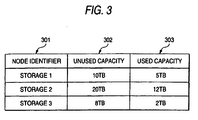
- FIG. 3 is a diagram showing an exemplary structure of the storage capacity management table 135, which stores information about storage area usage in the storage system 102 connected to the IP network 104.
- the storage capacity management table 135 has entries corresponding in number to the storage systems 102, for example, connected to the IP network 104. Each entry includes fields 301 to 303. Specifically, the field 301 is registered with a node ID for identifying the corresponding storage system 102; the field 302 is registered with information about the unused capacity of the corresponding storage system 102; and the field 303 is registered with information about the used capacity of the corresponding storage system 102.
- the unused capacity is information telling how much storage capacity is left unused with no physical volume created in the storage area of the disk device group 121 of the storage system 102.
- the used capacity tells how much storage capacity is already in use as physical volumes in the storage area of the disk device group 121.
- the storage area of "Storage 1" has 10T-Bytes of unused capacity, and 5T-Bytes of used capacity.
- the storage capacity management table 135 is under the management of the network management program 132. Accordingly, every time the storage system connected to the IP network 104 is created (or deleted) with any new physical volume, the network management program 132 responsively updates the contents of the storage capacity management table 135.
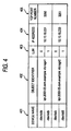
- FIG. 4 is a diagram showing an exemplary structure of the disk path management table 111 in the server 101.
- the disk path management table 111 stores names of virtual storages (in the below, "disk devices") to be used by the server 101 via the IP network 104, and information for the server 101 to access these disk devices.
- the disk path management table 111 has entries corresponding in number to the disk devices to be used by the server 101.
- Each entry includes fields 401 to 405.
- the field 401 is registered with a device name provided in the server 101 to the corresponding disk device;
- the field 402 is registered with an object ID of an SCSI object including the corresponding disk device;
- the field 403 is registered with a LUN of a volume corresponding to the disk device;
- the field 404 is registered with an IP address of a physical port assigned to the SCSI object including the corresponding disk device;
- the field 405 is registered with a TCP port number of the physical port assigned to the SCSI object including the corresponding disk device.
- the disk device is a unit used for the storage area in programs exemplified by an operating system ("OS") to be executed by the server 101.
- the disk device is structured by one or more volumes.
- the device name is exemplified by "/dev/had” as shown in FIG. 4 .
- the contents of the disk path management table 111 maybe set manually by system managers, and the device names and others may be set arbitrarily by the OS on the server 101 or the path management program 110.
- one SCSI object e.g., SCSI target
- SCSI object may include a plurality of disk devices, or a plurality of SCSI objects may structure a single disk device.
- the SCSI object is the one structured by one or more volumes.
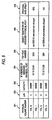
- FIG. 5 is a diagram showing an exemplary structure of the volume information table 123 in the storage system 102.
- the volume information table 123 stores property information of the physical volumes created by the respective storage systems 102.
- the volume information table 123 has entries corresponding in number to the physical volumes of the storage system 102. Each entry has fields 501 to 507.
- the field 501 is registered with a physical volume number that is an identifier of the corresponding physicalvolume; the field 502 is registered with a LUN of a volume corresponding to the physical volume; the field 503 is registered with a capacity of the corresponding physical volume; the field 506 is registered with an object ID of an SCSI obj ect including the corresponding physical volume; the field 504 is registered with an IP address assigned to the physical port interrelated to the SCSI object including the corresponding physical volume; the field 505 is registered with a port number of a TCP port to be used for establishing a TCP connection with the SCSI object including the corresponding physical volume; and the field 507 is registered with information indicating whether or not an IPSec processing unit is included in an HBA or others having the physical port corresponding to the physical volume.
- the volume information table 123 is under the management of the storage system 102. Thus, after creation of physical volumes, the storage system 102 creates volume properties every time creating any volume from the resulting physical volumes. Thus created volume properties are registered with the volume information table 123.
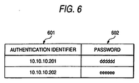
- FIG. 6 is a diagram showing an exemplary structure of the password management table 124 in any device connected to the IP network 104.
- the password management table 124 has entries corresponding in number to the other devices with which encrypted transfer is performed. Each entry has fields 601 and 602. Specifically, the field 601 is registered with information about an authentication ID of the other device for encrypted transfer using IPSec, and the field 602 is registered with a password used for authentication under IKE during the encrypted transfer.
- the password management table 112 is updated responding to every password registration.
- the user issues a volume creation request to the management server 103.
- the user includes also a request for the property (in this example, security level) of the resulting volume.
- the management server 103 searches the port attribute table 134 and the storage capacity management table 135 for the storage device 102 that is capable of volume creation meeting the user's request (in this example, storage capacity and security level).
- the management server 103 instructs thus found storage system 102 for volume creation as requested by the user. Especially if the security level (in this example, encrypted transfer using IPSec) requested by the user is high, the management server 103 instructs the storage system 102 to assign the resulting volume to the physical port belonging to the HBA or others including the IPSec processing unit. In the below, such a physical port is referred to as physical port with IPSec.
- the management server 103 forwards the completion notice and information to the user, e.g., the server 101 or manager.
- the information is the one needed to use the volume such as IP address corresponding to the volume.
- the user uses thus provided information to use the created volume, e.g., disk device creation using the volume.
- the server 101 first forwards an authentication ID and a password in accordance with IPSec protocol to the storage system 102 including the volume. Using thus provided authentication ID and the password, the storage system 102 authenticates the server 101. If the server 101 is authenticated by the storage system 102, the server 101 encrypts data to be stored in the volume, and the resulting data is transmitted to the storage system 102.
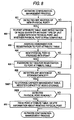
- FIG. 7 is a diagram showing an exemplary overall procedure of a volume assignment process of the present embodiment.
- the management server 103 executes a network configuration management process until a volume creation request comes from the server 101 or a manager (Step 701).
- the management server 103 accordingly executes a volume creation/assignment process (Step 703). After this process, any new volume becomes available for the server 101.
- the Steps 701 and 703 will be described in detail later.
- FIG. 8 is a diagram showing the procedure of the network configuration management process to be executed by the management server 103.
- the management server 103 updates the contents of various tables by detecting any addition of new physical port 115 and others to the IP network 104, whether thus added physical port is provided with IPSec, whether the storage system 102 is increased in capacity, and the like.
- the management server 103 keeps checking whether the IP network 104 is connected with any new physical port 115 and others. This check is not necessarily done all the time, and may be done at regular intervals, or at arbitrary time. Specifically, the management server 103 may be notified of any addition of new physical port manually by the system manager, or the management server 103 may regularly collect structure information about any device connected to the IP network 104 over the control network 105.
- the management server 103 maycollect MIB (Management Information Base) from the device connected to the IP network 104 using SNMP (Simple Network Management Protocol).
- MIB Management Information Base
- SNMP Simple Network Management Protocol
- the management server 103 may detect an SCN (State Change Notification) issued by the iSNS server over the control network 105.
- the iSNS is the known technique defined by the "Internet Storage Name Service being the Internet draft, and therewith, the IP-SAN devices and FC-SAN devices can be found, identified, and managed (for reference, ⁇ URL: http://www.ietf.org/internet-drafts/draft-ietf-ips-isns-21 .txt>)(Step 801).
- the management server 103 collects information about whether the newly-added physical port is provided with IPSec, and the node ID and the node type of the device including the physical port. Then, the management server 103 registers thus collected information with the port attribute table 134. Such information may be collected through the system manager's manual input to the management server 103, or the management server 103 may automatically collect such information using MIB and others from the device including thus newly added physical port (Step 802).
- the management server 103 assigns an IP address and an object ID to thus added physical port.
- the object ID is not necessarily assigned in this step. If not assigned in this step, the object ID is assigned to the physical port in the volume creation/assignment process to be executed by the management server 103 and the storage system 102.
- the IP address may be assigned through the system manager's manual input to the management server 103, or the management server 103 may automatically assign the IP address using a program such as a DHCP (Dynamic Host Configuration Protocol).
- DHCP Dynamic Host Configuration Protocol
- the object ID may be assigned through the system manager's manual input to the management server 103, or the device including the newly-added physical port may automatically assign the object ID to the port.
- the management server 103 uses a notice provided by the system manager or information such as MIB. The detection result is registered with the port attribute table 134. If no object ID is assigned, the field 202 in FIG. 2 becomes blank in the storage system 102 having a node ID of "Storage 2", and the physical port having assigned with the IP address of 10.10.10.204 (Step 803).
- the management server 103 determines whether or not the added physical port is provided with IPSec, specifically, whether the HBA or others including the added physical port is provided with an IPSec processing unit (Step 804).
- the management server 103 When the added physical port is provided with IPSec, the management server 103 makes a setting of an authentication ID and a password to be used by the added physical port at the time of IKE authentication. That is, the management server 103 provides the system manager with a notice about setting of an authentication ID and a password. The system manager then accordingly makes information input of an authentication ID and a password for the new physical port over an input interface of the management server 103. The management server 103 then registers thus input authentication ID and password with the port attribute table 134 (Step 805).
- Step 801 If no newphysical port is found in Step 801, if the physical port newly added in Step 804 is not provided with IPSec, or after Step 805 is through, the management server 103 makes a detection whether the storage system 102 connected to the IP network shows any change in storage capacity, and whether the device including the new physical port is the storage system 102. Such detections are done similarly to the case of connection detection of physical port to the IP network 104, i.e., the system manager's manual setting, or regularly collection of structure information using MIB and others (Step 806).
- the management server 103 If detecting any addition of the storage system 102 or any storage capacity change of the existing storage device 102, the management server 103 accordingly registers the storage capacity of the newly-added storage system 102 (or the storage system 102 showing some changes) with the storage capacity management table 135.
- the management server 103 may collect the storage capacity information of the storage system 102 similarly to the case of physical port detection (Step 807).
- the management server 103 makes a detection whether any physical port is deleted from the network 104, more specifically, whether any physical port is removed from the network 104. Such a detection may be done by detecting the IP address of the deleted physical port using the system manager's notice or regularly-collected information such as MIB (Step 808).
- the management server 103 specifies information about the deleted physical port through search of the field 203 of the port attribute table 134. Then, thus specified information is deleted from the port attribute table 134 (Step 809).
- FIGS. 9 and 10 are both a diagram showing the volume creation/assignment process to be executed by the management server 103 and the storage system 102.
- the volume creation/assignment process is executed responding to a volume creation request coming from the server 101 or the manager.
- the volume creation request includes information about the storage capacity required for a volume to be created, and the access security level for the volume, e.g., whether or not accessing the volume requires encryption using IPSec.
- the management server 103 Based on the information about the access security level for the volume included in the volume creation request, the management server 103 first determines whether accessing the volume requires encrypted transfer using IPSec (Step 901).
- the management server 103 specifies any physical port provided with no IPSec through search of the field 205 of the port attribute table 134.
- the management server 103 specifies the IP address of thus specified physical port, and the node ID of the storage system 102 including the physical port.
- the management server 103 makes a search of the storage capacity management table 135 using thus specified node ID, and then checks the unused capacity of the storage system 102 having the specified node ID. From the storage systems 102 having the specified node ID, the management server 103 then specifies the storage system 102 having the unused capacity equal to or more than the storage capacity of the volume requested for creation (Step 902).
- the management server 103 then issues a command for volume creation with the storage capacity requested by the server or the system manager.
- the storage system 102 After receiving the command for volume creation, the storage system 102 starts creating a volume having the requested storage capacity. After completion of volume creation, the storage system 102 forwards a completion notice to the management server 103.
- the management server 103 Upon reception of the completion notice, the management server 103 issues a command to the storage system 102 having been through with volume creation.
- the command is the one instructing the storage system 102 to assign thus created volume to a physical port without IPSec.
- This command includes information that is collected by the management server 103 in Step 902 about the IP address assigned to the physical port without IPSec in the specified storage system 102.
- the storage system 102 assigns the created volume to the specified physical port.
- the storage system 102 determines a TCP port number for establishing a TCP connection to the created volume.
- the storage system 102 may automatically determine the TCP port number, or the server 101 or the manager having issued the volume creation request may be encouraged to determine the TCP port number.
- the management server 103 may automatically determine the TCP port number, or encourage the server 101 or the system manager having issued the volume creation request to determine the TCP port number. And thus determined TCP port number may be included in the port assignment command.
- the storage system 102 notifies the management server 103 of the result (Step 903).
- the management server 103 separately issues the volume creation command and the port assignment command. In an alternate manner, these commands may be issued as one command. Described below is the operation procedure in Step 903 in such a structure.
- the management server 103 issues a volume creation/ port assignment command to the storage system 102 specified in Step 902.
- This command is for volume creation with the storage capacity requested by the server or the manager, and for assigning the created volume to a physical port 125 having no IPSec.
- This command includes the information that is collected by the management server 103 in Step 902 about the IP address assigned to the physical port without IPSec in the specified storage system 102. Further, the command may include the TCP port number for use at the time of establishing a TCP connection to the created volume.
- the storage system 102 After receiving the volume creation/port assignment command, the storage system 102 accordingly creates a volume of the requested storage capacity. If failed in volume creation, the storage system 102 issues error information with respect to the management server 103. If succeeded in volume creation, the storage system 102 assigns the resulting volume to the designated physical port 125. After completion of such assignment, the storage system 102 notifies the management server 103 of the result.
- Step 906 If no such storage system 102 capable of volume creation as requested in Step 902, or if Step 903 is not completely through due to failure of the storage system 102, for example, the management server 103 notifies the error information to the server 101 or the manager having issued the volume creation request, and then terminates the volume creation/assignment process (Step 906).
- the management server 103 updates the contents of the storage capacity management table 135 and the volume information table 123. To be specific, in the storage capacity management table 135, the management server 103 decreases the capacity of the created volume from the unused capacity of the storage system 102 having created the volume in Step 903, and from the used capacity thereof, increases the capacity of the created volume.
- the management server 103 To the storage system 102 having been through volume creation in Step 903, the management server 103 also issues a command for updating the volume information table 123. Responding to the command, the storage system 102. adds an entry to the volume information table 123 to cover any required information about the volume created in Step 903.
- the information includes the physical volume number of a physical volume corresponding to the created volume, the LUN number assigned to the volume, the storage capacity of the volume, the IP address of the port assigned with the volume, the TCP port number to be used to establish the TCP connection to the volume, the object ID assigned to the volume, and whether or not the port assigned with the volume is provided with IPSec.
- the management server 103 encourages the system manager to make input of an object ID, and the system manager responsively manually makes input of the object ID to the management server 103. Then, the management server 103 instructs the storage system 102 to update the volume information table 123 with the object ID. In an alternate manner, any device including a physical port having been assigned with a volume may automatically assign an object ID to the physical port (Step 905).
- Step 905 the management server 103 issues a volume creation completion notice to the server 101 or the system manager having issued the volume creation request.
- the volume creation completion notice includes information about access paths to the created volume, i.e., the IP address and the TCP port number of the physical port having been assigned with the created volume, and the LUN and the object ID assigned to the volume (Step 907).
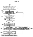
- the management server 103 makes a search of the field 205 of the port attribute table 134 to specify which physical port is provided with IPSec. Then, the management server 103 specifies the node ID of the storage system 102 having the IP address of the specified physical port and the physical port itself. Then, the management server 103 makes a search of the storage capacity management table 135 using the specified node ID to check the unused capacity of the storage system 102 having thus specified node ID. From the storage systems 102 having the specified node ID, if plural, the management server 103 specifies the storage system 102 having the unused capacity equal to or more than the storage capacity of the volume requested for creation (Steps 1001 and 1002 of FIG. 10 ).
- the management server 103 issues a command for creating a volume with the storage capacity requested by the server or the system manager.
- the storage system 102 After receiving the command, the storage system 102 goes through volume creation with the requested storage capacity. After completion of volume creation, the storage system 102 forwards a notice of indicating completion of volume creation to the management server 103.
- the management server 103 Upon reception of the notice, to the storage system 102 having created the volume, the management server 103 issues a command for assigning the created volume to the physical port with IPSec.
- This command includes information that is collected by the management server 103 in Step 1002 about the IP address assigned to the physical port with IPSec locating in the specified storage system 102.
- the storage system 102 In response to the port assignment command provided by the management server 103, the storage system 102 accordingly assigns the created volume to the designated physical port. After such assignment, the storage system 102 notifies the management server 103 of the result (Step 1003).
- the management server 103 separately issues the volume creation command and the port assignment command. In an alternate manner, these commands may be issued as one command. Described below is the operation procedure in Step 1003 in such a structure.
- the management server 103 issues a volume creation/ port assignment command to the storage system 102 specified in Step 1002.
- This command is also for volume creation with the storage capacity requested by the server or the manager, and for assigning the created volume to a physical port having IPSec.
- This command includes information that is collected by the management server 103 in Step 1002 about the IP address assigned to the physical port with IPSec locating in the specified storage system 102.
- the storage system 102 After receiving the volume creation/port assignment command, the storage system 102 accordingly creates a volume of the requested storage capacity. If failed in volume creation, the storage system 102 issues error information with respect to the management server 103.
- the storage system 102 assigns the resulting volume to the designated physical port. After completion of such assignment, the storage system 102 notifies the management server 103 of the result.
- Step 1002 If no such storage system 102 capable of volume creation as requested in Step 1002 is found on the system, if no physical port is provided with IPSec, or if Step 1003 is not completely through due to failure of the storage system 102, for example, the management server 103 notifies error information to the server 101 or the system manager having issued the volume creation request, and then terminates the volume creation/assignment process (Step 1008).
- Steps 1002 and 1003 are successfully through, the management server 103 executes an authentication key agreement process to register a password to be used for IKE authentication with the device using the IPSec.
- the authentication key agreement process will be described in detail later by referring to FIG. 11 .
- the management server 103 updates the contents of the storage capacity management table 135 and the volume information table 123. To be specific, in the storage capacity management table 135, the management server 103 decreases the capacity of the created volume from the unused capacity of the storage system 102 having created the volume in Step 1003, and from the used capacity thereof, increases the capacity of the created volume.
- the management server 103 To the storage system 102 having been through volume creation in Step 1003, the management server 103 also issues a command for updating the volume information table 123. Responding to the command, the storage system 102 adds an entry to the volume information table 123 to cover any required information about the volume created in Step 1003.
- the information includes the physical volume number of a physical volume corresponding to the created volume, the LUN number assigned to the volume, the storage capacity of the volume, the object ID assigned to the volume, and whether or not the port assigned to the volume is provided with IPSec (Step 1006) .
- Step 1006 or 1008 the management server 103 issues a volume creation completion notice to the server 101 or the system manager having issued the volume creation request. This is the end of the volume creation/assignment process with the requested volume.
- the server 101 After receiving the volume creation completion notice, the server 101 provides the created volume with a device name for the purpose of handling the volume as a disk device.
- the OS operating on the server 101 may automatically provide a device name, or the user of the server 101 may manually determine it.
- the server 101 adds the disk path management table 111 with the device name provided to the volume, and path information for accessing the volume included in the volume creation completion notice, i. e. , the object ID and LUN assigned to the volume, and the IP address and the TCP port number of the port having been assigned with the volume.
- the management server 103 determines whether the server 101 having issued the volume creation request includes a physical port 115a with IPSec. This is for determining the security level requested potentially by the server 101. To be specific, the management server 103 makes a search of the port attribute table 134 based on the IP address of the server 101 having issued the volume creation request so as to specify whether the server 101 has the physical port 115a with IPSec.
- the management server 103 determines that accessing the created volume requires security protection. Thus, the management server 103 instructs the storage system 102 to assign the physical port with IPSec to the created volume. On the other hand, in the case where the server 101 having issued the volume creation request has no physical port 115a with IPSec, the management server 103 determines that accessing the created volume does not require security protection. Therefore, the management server 103 instructs the storage system 102 to assign a physical port 115b without IPSec to the created volume.
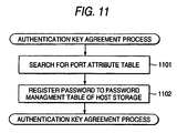
- FIG. 11 is a diagram showing the detailed procedure of the authentication key agreement process to be executed by the management server 103.
- Step 702 of the volume assignment process when the server 101 issues a volume creation request, the management server 103 having started the authentication key agreement process makes a search of the port attribute table 134 to specify the authentication IDs and the passwords of the physical ports 115 and 125.
- the physical port 115 is the one located in the server 101 having issued the volume creation request
- the physical port 125 is the one assigned with the volume in Step 903 or 1003.
- the management server 103 searches the port attribute table 134 for those authentication IDs and passwords based on the IP addresses assigned to the physical ports.
- Step 702 of the volume assignment process if the manager issues a volume creation request, the management server 103 having started the authentication key agreement process issues a command for the manager to designate the server 101 for permitting access to the created volume.
- the management server 103 specifies the authentication IDs and the passwords of the physical port 115 located in the server 101 and the physical port assigned with the volume in Step 903 or 1003 through search of the port attribute table 134.
- the management server 103 searches the port attribute table 122 for the authentication ID and the password of the physical port 115a located in the server 101 which is supposed to be allowed for access (in the below, "access-permitted server 101") based on the node ID of the access-permitted server 101.
- the management server 103 also searches the port attribute table 122 for the authentication ID and the password of the physical port 125a having been assigned with the volume based on the IP address assigned thereto (Step 1101).
- the management server 103 After specifying the authentication IDs and the passwords for various physical ports, the management server 103 forwards a command to the storage system 102.
- the command is for registering, with the password management table of the storage system 102, the authentication ID and the password selected from those specified in Step 1101 for use with the physical port 115 of the server 101.
- Also forwarded is another command for registering, with the password management table of the server 101, the authentication ID and the password from those specified for use with the physical port 125a of the storage system 102.
- the management server 103 when the server 101 and others are not asking for the high security level, the management server 103 so applies control that the created volume is assigned to any physical port having no IPSec. This is not restrictive, and even if the server 101 and others are not asking for the high security level, the management server 103 may so apply control that the created volume is assigned to any physical port with IPSec. Although this will secure the security more than necessary, this enables volume assignment even if the storage system having some unused capacity has only physical ports with IPSec.
- the management server 103 when the management server 103 notifies the server 101 of volume creation, the path information to the storage system 102 having been through with volume creation is forwarded theretogether. This excludes other servers 101 to acquire information needed for accessing the created volume. As a result, the created volume is available only for the server 101 notified of volume creation.
- iSCSI defined is a process (discovery) for the server to find any object (target) included in any arbitrary storage system 102, i. e. , to acquire path information.
- a plurality of servers 101 can share the path information about volume access.
- discovery denotes the operation of an SCSI initiator executed to acquire information needed to log in an SCSI target through inquiry for a computer in charge of a name assigned to the SCSI target.
- a computer is referred as "name service server” below.
- name service protocol corresponding to the iSCSI
- SLP Service Location Protocol
- SLP Service Location Protocol
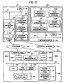
- FIG. 12 is a diagram showing an exemplary system structure of the second embodiment.
- the main difference from the first embodiment is that the management server 103 includes a name service server in addition to the management server 103. Note that, in the below, any component identical to that of the first embodiment is provided with the same reference numeral.
- the management server 103 is a general computer similarly to the first embodiment, and includes a processor, memory, and a network adapter.
- the memory stores the network management program 132, a name service program 1201, and the network configuration database 133.
- the network configuration database 133 is provided with the port attribute table 134, the storage capacity management table 135, and a storage address information table 1202.
- the management server 103 By executing the network management program 132 in addition to the processes in the first embodiment, after volume creation, the management server 103 registers, with its own storage address information table 1202, the access path to the created volume and the object ID of the server 101 accessible to the volume.
- the access path means information needed for volume access. In this manner, the management server 103 can provide a plurality of servers 101 with access path information about any specific one volume.
- the management server 103 By executing also the name service program 1201, the management server 103 specifies information needed to log in the SCSI target. Such specification is made based on the storage address information table 1202 with respect to a discovery request of the SCSI target that is received from the server 101 connected to the IP network 104. Then, the management server 103 forwards thus specified information to the server 101 from which the discovery request came.
- the management server 103 notifies the server 101 of the object ID, the IP address, and the TCP port number of the SCSI target requested by the discovery request.
- the name service program 1201 and the storage address information table 1202 are both stored in the memory 129 of the management server 103. In an alternative structure, those programs may be operated by not the management server 103 but by another computer.
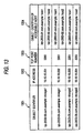
- FIG. 13 is a diagram showing an exemplary structure of the storage address information table 1202, which takes charge of managing information needed for the server 101 connected to the network 104 to access an SCSI target locating in the storage system 102 that is also connected to the network 104.
- This storage address information table 1202 includes entries corresponding in number to the SCSI targets in the storage system 102 connected to the network 104.
- Each entry has fields 1301 to 1304. Specifically, the field 1301 is registered with an object ID assigned to an SCSI target corresponding to the entry; the field 1302 is registered with an IP address assigned to the SCSI target; the field 1303 is registered with a TCP port number corresponding to the IP address of the SCSI target; and the field 1304 is registered with an object ID assigned to the server 101 that is accessible to the corresponding SCSI target.
- the field 1304 of any one specific entry stores object IDs as many as the servers 101 accessible to the SCSI target corresponding to the entry. Every time a volume is created, the management server 103 updates the storage address information table 1202.
- the information to be stored in the storage address information table 1202 has a dependency on a protocol to be used for name service.
- the storage address information table 1202 also stores information about those attributes.
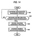
- FIG. 14 is a diagram showing an exemplary overall procedure of a volume assignment process of the second embodiment.
- Steps 1401 and 1402 are the same as Steps 701 and 702 of FIG. 8 in the first embodiment, and thus are not described again.
- the management server 103 After detecting a volume creation request from the server 101, the manager, or others in Step 1402, the management server 103 executes a volume creation/assignment process (Step 1403) and a storage address notification process (Step 1404). These processes will be described in detail later.
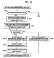
- FIGS. 15 and 16 are both a diagram showing an exemplary procedure for the volume creation/assignment process (Step 1403 of FIG. 14 ) to be executed by the management server 103 and the storage system 102.
- a volume creation request coming from the server 101 or the manager to the management server 103 includes information about the storage capacity required for a volume to be created, and the security level for the volume, e. g. , whether accessing the volume requires encryption using IPSec or not.
- the management server 103 may determine the security level depending on the property of the physical port of the server 101.
- Steps 1501 to 1505, and 1508 are the same in process as Steps 901 to 906 in the volume creation/assignment process of FIG. 9 in the first embodiment, and thus are not described again.
- Steps 1601 to 1606, and 1609 are the same in process as Steps 1001 to 1006, and 1008 in the volume creation/assignment process of FIG. 10 in the first embodiment, and thus are not described again.
- Step 1505 the management server 103 registers, as a new entry with the storage address information table 1202, information included in the assignment request to the physical port issued with respect to the storage system 102 in Step 1503.
- the information herein includes the IP address, the TCP port number, and the object ID.
- the management server 103 determines which server 101 is accessible to the volume created in Step 1503. The management server 103 then registers the object ID of thus determined server 101 to the field 1304 of the entry that is newly added to the storage address information table 1202.
- the management server 103 may encourage the manager to register the server 101 accessible to the created volume. If the volume creation request comes from the server 101, the server 101 may be registered with the storage address information table 1202 by the management server 103 as the one accessible to the created volume.
- the servers 101 connected to the network 104 may be divided into a plurality of groups in advance, and the management server 103 may register every server 101 in the group (the server 101 having issued the volume creation request included) with the storage address information table 1202 as the servers 101 accessible to the created volume (Step 1506).
- the management server 103 issues a volume creation completion notice (information about access paths is not included) to the server 101 or the manager having issued the volume creation request. This is the end of the volume creation/assignment process for the case where the requested volume is not in need for the encrypted transfer.
- Step 1606 the management server 103 registers, as a new entry with the storage address information table 1202, the IP address, the TCP port number, and the object ID included in the assignment request to the physical port issued with respect to the storage system 102 in Step 1603.
- the management server 103 determines which server 101 is accessible to the volume created in Step 1603. The management server 103 then adds the object ID of thus determined server 101 to the field 1304 of the entry that is newly added to the storage address information table 1202.
- the ways to determine the accessible server 101 are similar to those described by referring to FIG. 15 (Step 1607).
- the management server 103 then issues a volume creation completion notice (information about access paths is not included) to the server 101 or the manager having issued the volume creation request.
- FIG. 17 is a diagram showing an exemplary procedure for a storage address notification process to be executed in Step 1405 of FIG. 14 .
- the management server 103 makes a search of the storage address information table 1202 to specify the object ID, the IP address, the TCP port number assigned to the volume created in Step 1403, and the server 101 accessible to the created volume (Step 1701).
- the management server 103 notifies the server 101 specified in Step 1701 of the object ID, the IP address, and the TCP port number specified also in Step 1701.
- the management server 103 operating as the iSNS server issues an SCN to the server 101 to request discovery to the server 101 connected to the network 104 (Step 1702).
- the server 101 connected to the network 104 handles the management server 103 as a name service server, and in the present embodiment, as an iSNS server.
- the server 101 issues a discovery request to the management server 103 to receive information about making access to a target for its use.
- FIG. 18 is a diagram showing an exemplary procedure for a process to be executed when the management server 103 receives the discovery request. In the below, such a process is referred to as "name service process”.
- the management server 103 is monitoring whether any discovery request comes from the server 101 (Step 1801).
- the management server 103 After receiving the discovery request from the server 101, the management server 103 makes a search of the storage address information table 1202 to specify which SCSI target is accessible by the server 101 having issued the discovery request. The management server 103 then acquires from the storage address information table 1202 the object ID, the IP address, and the TCP port number of the SCSI target accessible by the server 101 having issued the discovery request (Step 1802).
- the management server 103 then notifies the server 101 having issued the discovery request of the object ID, the IP address, and the TCP port number acquired in Step 1802 (Step 1803).
- the management server 103 can perform volume provision to users in a more flexible manner.
- the management server 103 and others assign a plurality of physical ports to the created volume, thereby providing a plurality of access paths to the created volume.
- This allows both types of a physical port usable with IPSec and another unusable with IPSec to be assigned to a singly created volume. That is, the volume can be accessed by several different access paths.
- the management server 103 notifies the server 101 of every access path plurally available.
- the server 101 having issued the discovery request includes an HBA with IPSec, for example, notified are any access path(s) using encryptable physical port (s).
- the server 101 includes no HBA with IPSec for example, notified are any access path(s) using unencryptable physical volume (s).
- notified may be every access path using physical ports with IPSec, or every access path using physical ports without IPSec.
- the management server 103 can check by reference to the port attribute table.
- FIG. 19 is a diagram showing an exemplary structure of the volume information table 123 in the case where a volume is assigned with a plurality of ports.
- the volume information table 123 basically in the same structure as that of FIG. 5 except for some differences. That is, a field 1904 herein can plurally carry an IP address of the assigned port, and a field 1905 herein can carry an SCSI object of the assigned port and a TCP port number for use at the time of establishing a TPC connection both plurally. Further, correspondingly, a field for carrying information indicating whether the physical port denoted by the registered IP address has IPSec is provided plurally for a single object.
- to a physical port Vol. 0 assigned are an IP address 10.10.10.201 of the physical port with IPSec, and an IP address 10.10.10.202 of the physical port without IPSec.
- FIG. 20 is a diagram showing an exemplary structure of the storage address information table 1202 in this modification example.
- the storage address information table 1202 can register information about a plurality of access paths for a single SCSI target.
- the storage address information table 1202 can register information about a plurality of access paths for a single SCSI target.
- the storage address information table 1202 can register information about a plurality of access paths for a single SCSI target.
- the IP address 10.10.10.202 and a TCP port number 3260 of a port with IPSec is information about the IP address 10.10.10.202 and a TCP port number 3260 of a port with IPSec.
- volume creation/assignment process in Step 1403 and the storage address notification process in Step 1404 are executed in different order. Described below are only the difference.
- Step 1501 of the volume creation/assignment process no determination is made in Step 1501 of the volume creation/assignment process, and the procedure goes to Step 1601. No difference is observed in Steps 1601 and 1602.
- Step 1603 the management server 103 issues a command to the storage system 102 for assigning the created volume to both the physical port with IPSec and another without IPSec.
- the physical ports to be assigned with the created volume, desgnated by the management server 103 is arbitrary in number, two or more.
- the management server 103 registers an authentication ID and a password of the physical port with IPSec assigned to the volume. This registration is done with the password management table 112 of the server 101 accessible to the created volume. If the physical port with IPSec assigned to the volume is plural in number, their authentication IDs and passwords are all registered with the password management table 112.
- the volume information table 123 is updated in Step 1605, the volume information table 123 is registered with the IP addresses, and the TCP port numbers of every physical port assigned with the volume by the storage system 102 in Step 1603.
- the storage address information table 1202 is updated in Step 1608, the storage address information table 1202 is registered with the IP addresses, and the TCP port numbers of every physical port assigned with the volume by the storage system 102 in Step 1603. Also registered is information about whether the physical ports are provided with IPSec.
- Step 1702 of the storage address notification process in Step 1405 the management server 103 asks discovery for the server 101 accessible to the volume specified in Step 1701.
- the management server 103 After receiving the discovery request from the server 101, the management server 103 makes a search of the storage address information table 1202 to specify which object is accessible by the server 101 having sent the discovery request. Then, the management server 103 makes a search of the port attribute information 134 to check the property of the physical port located in the server 101 having sent the discovery request. Herein, the property indicates whether the IPSec is provided or not. If the server 101 from which the discovery request came includes an HBA with IPSec, the management server 103 forwards, to the server 101, the IP address and the TCP port number of the physical port with IPSec out of those assigned to the specified object. On the other hand, when the server 101 has no HBA with IPSec, the management server 103 forwards the IP address and the TCP port number of the physical port without IPSec out of those assigned to the specified object to the server 101.
- FIG. 21 is a diagram showing the exemplary procedure for the name service process to be executed by the management server 103 in this modification example.
- the management server 103 is monitoring whether any discovery request comes from the server 101 (Step 2101).
- the management server 103 After receiving the discovery request from the server 101, the management server 103 makes a search of the port attribute table 134 based on information about the IP address of the server 101 included in the discovery request so that the node ID of the server 101 having issued the discovery request is specified. The management server 103 then makes a search of the port attribute table 134 again this time based on thus specified node ID to specify whether the server 101 having issued the discovery request includes an HBA with IPSec (Steps 2102 and 2103).
- the management server 103 makes a search of the storage address information table 1202 to specify which SCSI target is accessible by the server 101 having issued the discovery request. Then, the management server 103 also makes a search of the storage address information table 1202 this time to specify the object ID, the IP address, and the TCP port number of the physical port with IPSec out of those assigned to the specified SCSI target (Step 2104).
- Step 2104 the management server 103 notifies the server 101 having issued the discovery request of the information specified in Step 2104, i.e., the object ID, the IP address, and the TCP port number of the specified physical port.
- the procedure then returns to Step 2101 (Step 2105).
- the management server 103 makes a search of the storage address information table 1202 to specify which SCSI target is accessible by the server 101 having issued the discovery request. Then, the management server 103 also makes a search of the storage address information table 1202 this time based on the specified SCSI target to specify the object ID, the IP address, and the TCP port number of the physical port without IPSec out of those assigned to the specified SCSI target (Step 2106).
- the management server 103 notifies the server 101 having issued the discovery request of the information specified in Step 2206, i.e. , the object ID, the IP address, and the TCP port number of the specified physical port. The procedure then returns to Step 2101 (Step 2107).
- the server 101 issuing a discovery request may also include therein a request for the security level (necessity for encryption).
- the server 101 becomes possible to ask for a target meeting its requesting security level to the management server 103.
- Vendor Specific Attribute denotes a bit string arbitrarily usable for providing any specific attribute to the iSNS server (management server 103 in the present embodiment) and the iSNS client (server 101 or storage system 102 in the present embodiment).
- the Vendor Specific Message is the one embedding arbitrary information into packets to be exchanged between the iSNS server and the iSNS client.
- Vendor Specific Attribute and “Vendor Specific Message” are specifically used as below. That is, as the attribute information to be registered with the Vendor Specific Attribute, defined is "whether or not IPSec is provided". Specifically, such a definition is made that the bit string is set to a bit 1 for every port under the management of the iSNS server, i.e. , for every IP address if the IPSec is usable. If IPSec is not usable, the bit string is set to a bit 0. Also defined is “Vendor Specific Message” foe exchanging such information as "necessity for encryption and "whether or not IPSec is provided”.
- a "whether or not IPSec is provided” message embedded with information about whether IPSec is usable is forwarded to the iSNS server.
- the iSNS client includes therein the "necessity of encryption” message embedded with whether encryption is needed for transmission to the iSNS server.
- the iSNS server makes a search of thus collected attribute information of iSNS client. If the discovery request is asking for encryption, the iSNS client can notify only the storage system 102 with IPSec from those accessible by the iSNS client.
- FIG. 22 is a diagram showing the exemplary procedure for the name service process in the case where the server 101 issues a discovery request including the security level (necessity for encryption) in the above anothermodification example .
- the management server 103 is monitoring whether any discovery request comes from the server 101 (Step 2201).
- the management server 103 After receiving the discovery request, the management server 103 makes a determination based on the information in the discovery request whether the server 101 having issued the discovery request is requiring encryption (Step 2202).
- the management server 103 goes through the process similarly to Steps 2104 and 2105 in the above modification example ( FIG. 21 ). To be specific, the management server 103 forwards, to the server 101, information about any SCSI target including the physical port with IPSec out of those accessible by the server 101 (Steps 2203 and 2204).
- the management server 103 goes through the process similarly to Steps 2106 and 2107 in the above modification example ( FIG. 21 ). To be specific, the management server 103 forwards, to the server 101, information about any SCSI target including the physical port without IPSec out of those accessible by the server 101 (Steps 2205 and 2206).
- the management server 103 may skip the process for determining whether IPSec is provided, and to the server 101, simply forwards information about the physical port assigned to the SCSI target accessible by the server 101. That is, when the server 101 is asking for the low security level, the management server 103 may notify the server of the information about the physical port having the higher security level among others of the SCSI target corresponding to the low security level.
- the management server 103 can instruct the storage system 102 to assign a plurality of physical ports 125 to a single volume. If this is the case, at the time of notifying the server 101 of volume creation completion, the management server 103 also notifies information about the physical ports 125 assigned to the volume. After receiving such a notice, the server 101 responsively uses thus notified physical ports 125 based on its own arbitrary requirement, e. g. , one of the notified physical ports 125 is generally used, and the other may be used for a substitution path.
- the physical ports included in the information notified to the server 101 may be those all high in security level, partially high in security level, or all low in security level.
- notified may be information including only the physical ports with the high security level, or information including at least one physical port with the high security level.
- the management server 103 upon reception of the discovery request, arbitrarily selects the physical port assigned to the volume accessible by the server 101, or depending on the type of the physical port of the server 101 or the security level requested by the server 101. The information about thus selected physical port is forwarded to the server 101.
- the issue here is that, in such a manner as in the second embodiment, the server 101 itself will find it difficult to change the security level as appropriate for volume access.
- a third embodiment considered is such a structure that the server 101 itself goes through physical port selection for volume access depending on the security level.
- the management server 103 after receiving the discovery request from the server 101, the management server 103 forwards, to the server 101, information about the object ID, the IP address, the TCP port number of every physical port assigned to the volume accessible by the server 101, and the information whether IPSec is provided thereto.
- the server 101 stores the information into the disk path management table 111.
- the server 101 uses information about a plurality of paths for the volume stored in the disk path management table 111 as a basis to select any physical port with IPSec for access only when encryption using IPSec is required.
- FIG. 23 is a diagram showing an exemplary structure of the disk path management table 111 in the present embodiment.
- the disk path management table 111 in the present embodiment is basically in the same structure as that of FIG. 4 in the first embodiment except for some differences. That is, herein, the device name may be assigned with a plurality of IP addresses, and a field 2306 is provided for registering information about whether or not IPSec is provided to the physical ports corresponding to these IP addresses.
- the port with the IP address of 10.10.10.201 and the TCP port number of 3260 is assigned with a port with the IP address of 10.10.10.202 and the TCP port number of 3260.
- the port with the IP address of 10.10.10.201 and the TCP port number of 3260 is the physical port with IPSec
- the port with the IP address of 10.10.10.202 and the TCP port number of 3260 is the physical port without IPSec,.
- FIG. 24 is a diagram showing an exemplary process of a path selection process to be executed by the server 101 through execution of the path management program 110.
- the server 101 uses the communications path using IPSec, otherwise, used is the communications path not using IPSec.
- the server 101 determines whether or not a volume access request has been issued (Step 2401).
- the server 101 makes a search of the disk path management table 1307 to check if there is any information about the volume requested for access (Steps 2402 and 2403).
- the server 101 issues a discovery request to the management server 103.
- the management server 103 having received the discovery request executes the name service process similarly to that of FIG. 22 .
- Step 2403 If there is information about the volume requested for access in Step 2403, or if the information about the volume requested for access is provided in Step 2404 by the management server 103, the server 101 determines whether an access path is plurally available for the volume requested for access or not (Step 2405).
- the server 101 determines whether the program having issued the volume access request is in need of encrypted transfer.
- the program for volume access may include information about the necessity of encryption for the access request for the server 101 to detect, or the user of the server 101 may in advance make a setting of the necessity of encryption for every program, and a determination may be made in accordance with the setting (Step 2406).
- the server 101 selects the access path using the physical port with IPSec on the target side. Then, the server 101 uses thus selected access path to carry out communications with the storage system 102 including the volume requested for access (Step 2409).
- the server 101 selects the access path using the physical port without IPSec on the target side. Then, the server 101 uses thus selected access path to carry out communications with the storage system 102 including the volume requested for access (Step 2408).
- the server 101 carries out communications with the storage system 102 using the only access path available for the volume requested to access.
- the server 101 receives information about a plurality of access paths together with a volume creation completion notice for registration with the disk path management table.
Description
- The present invention relates to a storage area management method in a storage area network (hereinafter, "IP-SAN") for establishing a connection among a plurality of computers and storage systems over the Internet Protocol (IP) network.
- For efficient data management in companies and others, establishing the Storage Area Network (SAN) is a popular option. The SAN is a network used for establishing a connection among a plurality of storage systems and computers. For data transfer over the SAN, the Fibre Channel Protocol is often used. In the below, such SAN is referred to as FC-SAN.
- Another type of SAN, i.e., IP-SAN, using an iSCSI is recently receiving attention. Here, the iSCSI is a protocol used for transmitting and receiving SCSI commands and data over the IP network. The SCSI commands are those conventionally used for communications between computers and storage systems, and the data is the one to be transferred based on those commands. For details about the iSCSI, refer to "iSCSI" authored by Julian Satran, et al., January 19, 2003, IETF, <URL: http://www.ietf.org/internet-drafts/draft-ietf-ips-iscsi-2 0.txt>. Compared with the FC-SAN, the IP-SAN has such an advantage that any existing LAN (Local Area Network) equipment that is already in use as infrastructure can be used therewith, for example.
- The issue here is that the IP-SAN requires much consideration for security. This is because, unlike the FC-SAN, a network used for the IP-SAN may not always be secure enough, e.g., the Internet, and intracorporate LAN. Further, it is common knowledge that attack methods and attack programs have been developed specifically for the IP network.
- For maintaining the security with the SAN, a possibility is access control between computers and storage systems, or encryption of a communications path. As a technique for realizing access control between computers and storage systems, considered are zoning for partitioning a communications path using switches or fabrics, or LUN masking (Logical Unit Number masking) for end-to-end access control between ports. The LUN masking technique is found in
JP-A-2001-265655 - For the IP-SAN, the IPSec may be used to encrypt the communications path between computers and storage systems. For details about the IPSec, refer to "Security Architecture for IP" authored by Stephen Kent and Randall Arkinson, November 1998, IETF, <URL: http://www.ietf.org/rfc/rfc2401.txt>. The IPSec is a technique of encrypting a communications path using a shared key. With IPSec, the shared key is managed under IKE (Internet Key Exchange), details of which are found in "The Internet Key Exchange (IKE)" authored by Dan Harkins and Dave Carrel, November 1998, IETF, <URL: http://www.ietf.org/rfc/rfc2409.txt>.
- The problem here is that devices to be connected to the IP-SAN are not all necessarily equipped with means for security protection as above. For example, some devices to be connected to the IP-SAN may be implemented with IPSec but some may not, and security protection is not necessarily always required for communications between computers and storage systems.
- In such cases, for system configuration, system managers are required to always pay attention to matters such as whether devices connected to a network have a safeguard for security protection, and the security level of system components. While paying attention as such, the system managers need to allocate storage systems connected to the network and their storage areas to computers also connected to the network. This problematically puts an enormous burden on the system managers. What is more, once such allocation settings are made by the system managers, computer users find it difficult to freely change the settings of storage area allocation. Further, the security level setting for communications between the computers and the storage systems may be unnecessarily high, resulting in a waste of system resources.
-
US 2002/0174306 A1 discloses virtual storage exchange system (VSX) that provides the storage device to a host computer using storage mapping rules. -
US 2003/0225801 Al disclose storage attributes that are device related including capacity, bandwidth, I/O rates, sequential/direct, reliability/error rates, concurrent copy capability, physical location, security, lease duration, cost, etc. - It is an object of this invention to avoid the above problems and provide a computer system that is easy to manage and makes economic use of available system resources.
- This object is met by the computer system defined in
claim 1 and the management computer defined in claim 12. - An embodiment is directed to a system including a computer for managing information about computers and storage systems to be connected to a network. In the below, such a computer is referred also to as "network management server". In response to any request coming from the computers, the network management server selects any of the storage systems that is satisfying predetermined requirements, and then instructs the storage system to create a storage area. The storage system accordingly creates a storage area following the predetermined requirements, and after completion, forwards a creation completion notice to the network management server.
- After receiving the notice, the network management server notifies the computers of information for using thus created storage area, e.g., network address assigned to a port of the storage system. Based on such information, the computers use the created storage area.
- Wherein, specifically, the information about the storage systems and others managed by the network management server is information about the security level. The request coming from the computers may also include a request about the security level. If this is the case, the network management server may search its own information for any storage system meeting the security level requested by the computers. The resulting storage system is then instructed to create a storage area.
- Note here that the security level may be information indicating whether or not an encryption process is executable in the devices for data transmission and reception.
- Other structures of the present invention will become more apparent from the following detailed description of embodiments and others.
-
-
FIG. 1 is a diagram showing an exemplary system structure of a first embodiment; -
FIG. 2 is a diagram showing an exemplary structure of a port attribute table; -
FIG. 3 is a diagram showing an exemplary structure of a storage capacity management table; -
FIG. 4 is a diagram showing an exemplary structure of a disk path management table; -
FIG. 5 is a diagram showing an exemplary structure of a volume information table; -
FIG. 6 is a diagram showing an exemplary structure of a password management table; -
FIG. 7 is a diagram showing an exemplary procedure for a volume assignment process; -
FIG. 8 is a diagram showing an exemplary procedure for a network configuration management process; -
FIG. 9 is a diagram showing an exemplary procedure for a volume creation/assignment process; -
FIG. 10 is a diagram showing the exemplary procedure for the volume creation/assignment process; -
FIG. 11 is a diagram showing an exemplary procedure for an authentication key agreement process; -
FIG. 12 is a diagram showing an exemplary system structure of a second embodiment; -
FIG. 13 is a diagram showing an exemplary structure of a storage address information table; -
FIG. 14 is a diagram showing an exemplary overall procedure of a volume assignment process of the second embodiment; -
FIG. 15 is a diagram showing an exemplary procedure for a volume creation/assignment process of the second embodiment; -
FIG. 16 is a diagram showing the exemplary procedure for the volume creation/assignment process of the second embodiment; -
FIG. 17 is a diagram showing an exemplary procedure for a storage address notification process; -
FIG. 18 is a diagram showing an exemplary procedure for a name service process; -
FIG. 19 is a diagram showing an exemplary structure of a volume information table; -
FIG. 20 is a diagram showing an exemplary structure of a storage address information table; -
FIG. 21 is a diagram showing the exemplary procedure for the name service process; -
FIG. 22 is a diagram showing the exemplary procedure for the name service process; -
FIG. 23 is a diagram showing an exemplary structure of a disk path management table; and -
FIG. 24 is a diagram showing an exemplary procedure for a path selection process. -
FIG. 1 is a diagram showing an exemplary system structure of a first embodiment. The system includes: a computer (in the below, referred also to as "server") 101; astorage system 102; and a network management server (in the below, referred also to as "management server") 103. The server and the storage system are connected to each other over anIP network 104. Acontrol network 105 connects among the server, the storage system, and the management server. - Note here that the system exemplarily shown in
FIG. 1 has theIP network 104 and thecontrol network 105 are each independent network. Alternatively, these networks may be shared as a single network. Theserver 101 and thestorage system 102 to be connected to theIP network 104 are both arbitrary in number. - The
server 101 performs data transmission and reception with thestorage system 102 over theIP network 104. TheIP network 104 is the one over which IP packets can be transferred. Specifically, such an IP network includes Ethernet LANs, Ethernet WANs (Wide Area Network), and wide area IP networks, lease lines, and others provided by local exchange carriers. - The
management server 103 performs transmission and reception of management information with theserver 101 and thestorage system 102 over thecontrol network 105. - The
server 101 is a general computer, and provided with a processor (in the below, referred also to as "CPU") 106,memory 107, and a host bus adapter (in the below, referred also to as "HBA") 108. TheCPU 106, thememory 107, and theHBA 108 are connected together via abus 109. The memory stores apath management program 110, a disk path management table 111, and a password management table 112. Herein, these programs are stored in thememory 107, for example, of theserver 101 via a portable storage device or over a network. - Through the execution of the
path management program 110, theprocessor 106 determines a data communications path between theserver 101 and thestorage system 102 over theIP network 104. This determination is made based on information stored in the disk path management table 111 about paths between the server and the storage system. Theprocessor 106 uses information coming from managers, users, other programs, and the like, as a basis for determining or changing the data communications path. - The path information stored in the disk path management table 111 is used by the
server 101 to make access to thestorage system 102 connected to theIP network 104. The disk path management table 111 also stores path property information, e. g. , whether the path is provided with the encryption property using IPSec. - For data encryption using IPSec between the
server 101 and the storage system before communications, there needs to set a cryptographic key needed for encryption to both theserver 101 and thestorage system 102 in charge of communications. To manage thus set cryptographic key, there are two ways: manual cryptographic key management, and automatic cryptographic key management. With the iSCSI draft, however, the manual cryptographic key management is prohibited. Also with the iSCSI draft, an IKE automatic key management protocol is required to be incorporated for automatic cryptographic key management. At the time of key exchange under IKE, an authentication process is executed mutually between theserver 101 and the storage system. The password management table 112 stores its own password needed for such authentication under IKE. Here, when the present invention is used under the circumstances that the iSCSI draft is not necessarily implemented, key setting may be done with the manual cryptographic key management, or with the automatic cryptographic key management other then IKE. - The
HBA 108 is connection equipment used for establishing a connection between theserver 101 and theIP network 104. TheHBA 108 has an Interface chip (hereinafter, referred also to as "IF chip") 113, aphysical port 115 for connection to theIP network 104, and anIPSec processing unit 127. Thephysical port 115 is always used for data transfer between theserver 101 and theIP network 104. - The
IF chip 113 is a circuit for exercising control over a packet process for packet transmission and reception to/from theIP network 104, e.g. , SCSI command encapsulation, and DMA (Direct Memory Access) transfer between thephysical port 115 and thememory 107 of theserver 101, and others. - The
IPSec processing unit 127 is a processor for going through processes of data encryption and decryption before communications, cryptographic key exchange and authentication between devices, for example. Prior to authentication, theIPSec processing unit 127 searches the password management table 112 stored in thememory 107 for a password needed for authentication of the device on the other end. - Note that the
HBA 108 in the present embodiment is assumed to execute processes required for encrypted transfer using IPSec. The issue here is that theHBA 108 of theserver 101 may not always be capable of going through the IPSec process. Accordingly, for distinction hereinafter, theHBA 108 capable of going through the IPSec process is referred to as HBA 108a, and the one not capable of going through the IPSec process is referred to as HBA 108b. - The
storage system 102 is provided withhost adapters CPU 116, adisk adapter 117,memory 119,cache memory 118, anddisk device group 121. Abus 122 establishes a connection among thehost adapters CPU 116, thedisk adapter 117, thememory 119, and thecache memory 118. Instead of such abus 122, a switch is an alternative option. Thedisk adapter 117 connects together thedisk device group 121 and thebus 122. Thememory 119 stores a volume information table 123, and a password management table 124. - The
CPU 116 makes access to thememory 119 via thebus 122 to execute a program stored in thememory 119. Thedisk adapter 117 exercises access control over theCPU 116 with respect to thedisk device group 121. Thecache memory 118 temporarily stores data to be transferred to theserver 101 or data coming therefrom. - The
disk device group 121 includes one or more of a disk device. Herein, instead of non-volatile memory such as the disk device, thedisk device group 121 may plurally include volatile memory such as a flash memory card. Each disk device has a physical storage area. From such a physical storage area belonging to each corresponding disk device, thestorage system 102 creates a logical storage area (in the below, referred to as "physical volume"). Using the physical volume as a unit, thestorage system 102 handles its own storage area as a single logical storage. Here, the disk device group structuring the physical volume may be in the RAID structure. - The
storage system 102 creates a volume from one or more physical volumes. The volume is a unit of the logical storage area that is provided to theserver 101, and is equivalent to a logical unit (LU) used with the SCSI protocol, for example. - The host adapters 120 each include a physical port 125 that is to be connected to the
IP network 104. Thehost adapter 120a also includes theIPSec processing unit 127 for executing a process needed for encrypted transfer using IPSec. In the present embodiment, thestorage system 102 includes, one each, thehost adapter 120a that executes a process for encrypted transfer using IPSec, and thehost adapter 120b that does not execute such a process. The number of the host adapters 120 is not surely restrictive, and thestorage system 102 may include the arbitrary number of thehost adopters storage system 102 may include either the host adapter 102a or 102b. - The volume information table 123 stores information that shows the interrelation between physical volumes and volumes. To be specific, stored therein are a volume number corresponding to a specific physical volume (hereinafter, referred to as logical unit number (LUN), a volume capacity, and identifier (ID) information (e.g., address) of the
physical port 115 assigned to the volume. Every time a volume is newly created, thestorage system 102 updates the contents of the volume information table 123. - The password management table 124 stores a password needed for authentication under IKE when the
host adapter 120a of thestorage system 102 executes the IPSec process. - The
management server 103 is a general computer, and includes a processor (in the below, referred also to as "CPU") 128,memory 129, and a network adapter 130. Abus 131 establishes a connection among theCPU 128, thememory 129, and the network adapter 130 . Thememory 129 stores anetwork management program 132, and anetwork configuration database 133. - The
network configuration database 133 includes a port attribute table 134, and a storage capacity management table 135. - With the port attribute table 134, information is registered for the
management server 103 to manage the physical port connected to theIP network 104. To be specific, with respect to a specific physical port, registered are a node identifier (ID) for uniquely distinguishing a device having the physical port, an address for any other devices to access the physical port, and information about whether an HBA or a host adapter having the physical port can execute the IPSec process. - With the storage capacity management table 135, information is registered for the
management server 103 to manage the storage capacity of thestorage system 102 connected to theIP network 104. To be specific, the information indicates the still-available capacity (hereinafter, "unused capacity") of the storage area and the already-used capacity thereof (hereinafter, "capacity of used area" or "used capacity") in therespective storage systems 102 connected to theIP network 104. Such information is registered with the storage capacity management table 135 for everystorage system 102. - The
processor 128 of themanagement server 103 executes thenetwork management program 132 for information collection via thecontrol network 105. Herein, the information is the one about the physical ports located in theserver 101 and thestorage system 102, and the one about the unused capacity and the used capacity in the storage. Then, based on thus collected information, themanagement server 103 creates or updates the port attribute table 134 and the storage capacity management table 135. - When a volume creation request comes from the
server 101, the system manager, or the like, themanagement server 103 responsively makes a search of the contents of the port attribute table 134 and the storage capacity management table 135. After the search, another request for creating a volume satisfying the requirements is issued with respect to thestorage system 102. Further, after receiving a volume creation completion notice from thestorage system 102, themanagement server 103 notifies completion of volume creation to theserver 101, the manager, or others. Herein, theserver 101 or the system manager is the one having issued the volume creation request. Then, themanagement server 103 collects passwords needed for authentication at the time of IKE, and issues a command for theserver 101 and thestorage system 102 to register any newly input password with the password management tables 112 and 117 . - Described now are the contents of the respective tables included in each device. In the present embodiment, although information is managed in the form of table, this is not surely restrictive.
-
FIG. 2 is a diagram showing an exemplary structure of the port attribute table 134, which stores property information about thephysical ports 115 and 125 (hereinafter, referred to as collectively "physical port 115 and others" or simply "physical port") connected to theIP network 104. - The port attribute table 134 has entries corresponding in number to the
physical ports 115 and others connected to theIP network 104. Each entry includesfields 201 to 207. Specifically, thefield 201 is registered with a node ID for identifying which device includes thephysical port 115 and others corresponding to the entry; thefield 202 is registered with an object identifier (ID) of an SCSI object assigned to the correspondingphysical port 115 and others; thefield 203 is registered with an IP address assigned to the correspondingphysical port 115 and others; thefield 204 is registered with a node type that is information for distinguishing which device has the correspondingphysical port 115 and others, i.e. , theserver 101 or thestorage system 102; thefield 205 is registered with information indicating whether theHBA 108 or the host adapter 120 having the correspondingphysical port 115 and others includes an IPSec processing unit; thefield 206 is registered with an authentication identifier (ID); and thefield 207 is registered with a password. - Here, assignment of an SCSI object to a physical port means that the
server 101 determines which physical port to use when using an SCSI object. Accordingly, once determined, theserver 101 is not allowed to use an SCSI object using any other physical port. - The object ID is an SCSI object identifier that is defined by SAM (SCSI Architecture Model). Herein, the SCSI object is a generic term for a device from which an SCSI command is issued (logically or physically: hereinafter, "SCSI initiator"), and a device that receives the SCSI command (logically or physically: hereinafter, "SCSI target"). The object ID is equivalent to an iSCSI name with iSCSI, and WWN with FC. The device to be connected to the
IP network 104 can have one or more SCSI objects. InFIG. 2 example, thestorage system 102 having a node ID of "Storage 1" has two SCSI objects (in this example, SCSI targets) of iqn.2003-03.com.example:storagel, and iqn.2003-04.com.example:storagel. - In the case that the
physical port 115 and others are assigned to no SCSI object, for example, thefield 202 will be blank. InFIG. 2 example, in thestorage system 102 having a node ID of "Storage 2", the physical port having assigned with the IP address of 10.10.10.204 has theblank field 202. This indicates that this physical port is assigned to no SCSI object. - The authentication ID identifies which terminal is in charge of key exchange at the time of IKE authentication during an encryption process using IPSec. The authentication ID is assigned to every physical port in which the IPSec can be used. The authentication ID may be the IP address assigned to the physical port, the combination of IP address and network mask, or the node ID.
- The password is used for IKE authentication, and similarly to the authentication ID, assigned to every physical port in which the IPSec can be used. The
field 207 stores, as passwords, password character strings under the Pre-shared key mode for password setting, or digital signatures, if used, those approved by the Certificate Authority. InFIG. 2 example, as to thephysical port 115 in "Host 1" having assigned with the IP address of 10.10.10.101, the IP address is used as the authentication ID with the Pre-Shared key mode for password setting, and thus thefield 206 stores 10.10.10.101, and thefield 207 stores a password character string of aaaaaa. - The port attribute table 134 is under the management of the
management server 103. Themanagement server 103 updates the port attribute table 134 responding to any addition to the system of newphysical port 115 and others, new volume assignment to thephysical port 115 and others, or password setting. -
FIG. 3 is a diagram showing an exemplary structure of the storage capacity management table 135, which stores information about storage area usage in thestorage system 102 connected to theIP network 104. - The storage capacity management table 135 has entries corresponding in number to the
storage systems 102, for example, connected to theIP network 104. Each entry includesfields 301 to 303. Specifically, thefield 301 is registered with a node ID for identifying the correspondingstorage system 102; thefield 302 is registered with information about the unused capacity of thecorresponding storage system 102; and thefield 303 is registered with information about the used capacity of thecorresponding storage system 102. - The unused capacity is information telling how much storage capacity is left unused with no physical volume created in the storage area of the
disk device group 121 of thestorage system 102. The used capacity tells how much storage capacity is already in use as physical volumes in the storage area of thedisk device group 121. - In
FIG. 3 example, the storage area of "Storage 1" has 10T-Bytes of unused capacity, and 5T-Bytes of used capacity. Herein, the storage capacity management table 135 is under the management of thenetwork management program 132. Accordingly, every time the storage system connected to theIP network 104 is created (or deleted) with any new physical volume, thenetwork management program 132 responsively updates the contents of the storage capacity management table 135. -
FIG. 4 is a diagram showing an exemplary structure of the disk path management table 111 in theserver 101. The disk path management table 111 stores names of virtual storages (in the below, "disk devices") to be used by theserver 101 via theIP network 104, and information for theserver 101 to access these disk devices. The disk path management table 111 has entries corresponding in number to the disk devices to be used by theserver 101. - Each entry includes
fields 401 to 405. Specifically, thefield 401 is registered with a device name provided in theserver 101 to the corresponding disk device; thefield 402 is registered with an object ID of an SCSI object including the corresponding disk device; thefield 403 is registered with a LUN of a volume corresponding to the disk device; thefield 404 is registered with an IP address of a physical port assigned to the SCSI object including the corresponding disk device; and thefield 405 is registered with a TCP port number of the physical port assigned to the SCSI object including the corresponding disk device. - Here, the disk device is a unit used for the storage area in programs exemplified by an operating system ("OS") to be executed by the
server 101. The disk device is structured by one or more volumes. In the present embodiment, the device name is exemplified by "/dev/had" as shown inFIG. 4 . The contents of the disk path management table 111 maybe set manually by system managers, and the device names and others may be set arbitrarily by the OS on theserver 101 or thepath management program 110. - Alternatively, one SCSI object, e.g., SCSI target, may include a plurality of disk devices, or a plurality of SCSI objects may structure a single disk device. The SCSI object is the one structured by one or more volumes.
-
FIG. 5 is a diagram showing an exemplary structure of the volume information table 123 in thestorage system 102. The volume information table 123 stores property information of the physical volumes created by therespective storage systems 102. The volume information table 123 has entries corresponding in number to the physical volumes of thestorage system 102. Each entry hasfields 501 to 507. Specifically, thefield 501 is registered with a physical volume number that is an identifier of the corresponding physicalvolume; thefield 502 is registered with a LUN of a volume corresponding to the physical volume; thefield 503 is registered with a capacity of the corresponding physical volume; thefield 506 is registered with an object ID of an SCSI obj ect including the corresponding physical volume; thefield 504 is registered with an IP address assigned to the physical port interrelated to the SCSI object including the corresponding physical volume; thefield 505 is registered with a port number of a TCP port to be used for establishing a TCP connection with the SCSI object including the corresponding physical volume; and the field 507 is registered with information indicating whether or not an IPSec processing unit is included in an HBA or others having the physical port corresponding to the physical volume. - The volume information table 123 is under the management of the
storage system 102. Thus, after creation of physical volumes, thestorage system 102 creates volume properties every time creating any volume from the resulting physical volumes. Thus created volume properties are registered with the volume information table 123. -
FIG. 6 is a diagram showing an exemplary structure of the password management table 124 in any device connected to theIP network 104. The password management table 124 has entries corresponding in number to the other devices with which encrypted transfer is performed. Each entry hasfields field 601 is registered with information about an authentication ID of the other device for encrypted transfer using IPSec, and thefield 602 is registered with a password used for authentication under IKE during the encrypted transfer. - The password management table 112 is updated responding to every password registration.
- In the present embodiment, if a user or a manager of the
server 101 wants to newly use the storage area of thestorage system 102, the user issues a volume creation request to themanagement server 103. In the request, the user includes also a request for the property (in this example, security level) of the resulting volume. After receiving such a volume creation request, themanagement server 103 searches the port attribute table 134 and the storage capacity management table 135 for thestorage device 102 that is capable of volume creation meeting the user's request (in this example, storage capacity and security level). - If the
storage system 102 meeting the user's request is found, themanagement server 103 instructs thus foundstorage system 102 for volume creation as requested by the user. Especially if the security level (in this example, encrypted transfer using IPSec) requested by the user is high, themanagement server 103 instructs thestorage system 102 to assign the resulting volume to the physical port belonging to the HBA or others including the IPSec processing unit. In the below, such a physical port is referred to as physical port with IPSec. - Then, after receiving a completion notice from the
storage system 102 telling that the volume creation is done, themanagement server 103 forwards the completion notice and information to the user, e.g., theserver 101 or manager. Herein, the information is the one needed to use the volume such as IP address corresponding to the volume. In response to the completion notice, the user uses thus provided information to use the created volume, e.g., disk device creation using the volume. In the case where theserver 101 carries out communications with respect to the volume thus secured with security, theserver 101 first forwards an authentication ID and a password in accordance with IPSec protocol to thestorage system 102 including the volume. Using thus provided authentication ID and the password, thestorage system 102 authenticates theserver 101. If theserver 101 is authenticated by thestorage system 102, theserver 101 encrypts data to be stored in the volume, and the resulting data is transmitted to thestorage system 102. - In the below, described is the processing procedure of the present embodiment in detail.
-
FIG. 7 is a diagram showing an exemplary overall procedure of a volume assignment process of the present embodiment. First, themanagement server 103 executes a network configuration management process until a volume creation request comes from theserver 101 or a manager (Step 701). When receiving a volume creation request from theserver 101 or the manager (Step 702), themanagement server 103 accordingly executes a volume creation/assignment process (Step 703). After this process, any new volume becomes available for theserver 101. TheSteps -
FIG. 8 is a diagram showing the procedure of the network configuration management process to be executed by themanagement server 103. In the network configuration management process, themanagement server 103 updates the contents of various tables by detecting any addition of newphysical port 115 and others to theIP network 104, whether thus added physical port is provided with IPSec, whether thestorage system 102 is increased in capacity, and the like. - Until receiving a volume creation request from the
server 101, for example, themanagement server 103 keeps checking whether theIP network 104 is connected with any newphysical port 115 and others. This check is not necessarily done all the time, and may be done at regular intervals, or at arbitrary time. Specifically, themanagement server 103 may be notified of any addition of new physical port manually by the system manager, or themanagement server 103 may regularly collect structure information about any device connected to theIP network 104 over thecontrol network 105. - To regularly collect the structure information about any device connected to the
IP network 104, themanagement server 103 maycollect MIB (Management Information Base) from the device connected to theIP network 104 using SNMP (Simple Network Management Protocol). Alternatively, if an iSNS (Internet Storage Name Service) server is connected to thecontrol network 105, themanagement server 103 may detect an SCN (State Change Notification) issued by the iSNS server over thecontrol network 105. Here, the iSNS is the known technique defined by the "Internet Storage Name Service being the Internet draft, and therewith, the IP-SAN devices and FC-SAN devices can be found, identified, and managed (for reference, <URL: http://www.ietf.org/internet-drafts/draft-ietf-ips-isns-21 .txt>)(Step 801). - If detecting any addition of new physical port to the
IP network 104, themanagement server 103 collects information about whether the newly-added physical port is provided with IPSec, and the node ID and the node type of the device including the physical port. Then, themanagement server 103 registers thus collected information with the port attribute table 134. Such information may be collected through the system manager's manual input to themanagement server 103, or themanagement server 103 may automatically collect such information using MIB and others from the device including thus newly added physical port (Step 802). - Thereafter, the
management server 103 assigns an IP address and an object ID to thus added physical port. Note here that the object ID is not necessarily assigned in this step. If not assigned in this step, the object ID is assigned to the physical port in the volume creation/assignment process to be executed by themanagement server 103 and thestorage system 102. The IP address may be assigned through the system manager's manual input to themanagement server 103, or themanagement server 103 may automatically assign the IP address using a program such as a DHCP (Dynamic Host Configuration Protocol). - The object ID may be assigned through the system manager's manual input to the
management server 103, or the device including the newly-added physical port may automatically assign the object ID to the port. For detection of thus assigned IP address and the object ID, themanagement server 103 uses a notice provided by the system manager or information such as MIB. The detection result is registered with the port attribute table 134. If no object ID is assigned, thefield 202 inFIG. 2 becomes blank in thestorage system 102 having a node ID of "Storage 2", and the physical port having assigned with the IP address of 10.10.10.204 (Step 803). - Then, based on the information collected in
Step 802, themanagement server 103 determines whether or not the added physical port is provided with IPSec, specifically, whether the HBA or others including the added physical port is provided with an IPSec processing unit (Step 804). - When the added physical port is provided with IPSec, the
management server 103 makes a setting of an authentication ID and a password to be used by the added physical port at the time of IKE authentication. That is, themanagement server 103 provides the system manager with a notice about setting of an authentication ID and a password. The system manager then accordingly makes information input of an authentication ID and a password for the new physical port over an input interface of themanagement server 103. Themanagement server 103 then registers thus input authentication ID and password with the port attribute table 134 (Step 805). - If no newphysical port is found in
Step 801, if the physical port newly added inStep 804 is not provided with IPSec, or afterStep 805 is through, themanagement server 103 makes a detection whether thestorage system 102 connected to the IP network shows any change in storage capacity, and whether the device including the new physical port is thestorage system 102. Such detections are done similarly to the case of connection detection of physical port to theIP network 104, i.e., the system manager's manual setting, or regularly collection of structure information using MIB and others (Step 806). - If detecting any addition of the
storage system 102 or any storage capacity change of the existingstorage device 102, themanagement server 103 accordingly registers the storage capacity of the newly-added storage system 102 (or thestorage system 102 showing some changes) with the storage capacity management table 135. Themanagement server 103 may collect the storage capacity information of thestorage system 102 similarly to the case of physical port detection (Step 807). - If no addition of the
storage system 102 or no capacity change of thestorage system 102 is detected inStep 806, or after Step 807 is through, themanagement server 103 makes a detection whether any physical port is deleted from thenetwork 104, more specifically, whether any physical port is removed from thenetwork 104. Such a detection may be done by detecting the IP address of the deleted physical port using the system manager's notice or regularly-collected information such as MIB (Step 808). - Once detected the IP address of the physical port deleted from the
network 104, themanagement server 103 specifies information about the deleted physical port through search of thefield 203 of the port attribute table 134. Then, thus specified information is deleted from the port attribute table 134 (Step 809). -
FIGS. 9 and10 are both a diagram showing the volume creation/assignment process to be executed by themanagement server 103 and thestorage system 102. The volume creation/assignment process is executed responding to a volume creation request coming from theserver 101 or the manager. The volume creation request includes information about the storage capacity required for a volume to be created, and the access security level for the volume, e.g., whether or not accessing the volume requires encryption using IPSec. - Based on the information about the access security level for the volume included in the volume creation request, the
management server 103 first determines whether accessing the volume requires encrypted transfer using IPSec (Step 901). - If determined in
Step 901 as not necessarily, themanagement server 103 specifies any physical port provided with no IPSec through search of thefield 205 of the port attribute table 134. Themanagement server 103 then specifies the IP address of thus specified physical port, and the node ID of thestorage system 102 including the physical port. Next, themanagement server 103 makes a search of the storage capacity management table 135 using thus specified node ID, and then checks the unused capacity of thestorage system 102 having the specified node ID. From thestorage systems 102 having the specified node ID, themanagement server 103 then specifies thestorage system 102 having the unused capacity equal to or more than the storage capacity of the volume requested for creation (Step 902). - To the
storage system 102 specified inStep 902, themanagement server 103 then issues a command for volume creation with the storage capacity requested by the server or the system manager. - After receiving the command for volume creation, the
storage system 102 starts creating a volume having the requested storage capacity. After completion of volume creation, thestorage system 102 forwards a completion notice to themanagement server 103. - Upon reception of the completion notice, the
management server 103 issues a command to thestorage system 102 having been through with volume creation. The command is the one instructing thestorage system 102 to assign thus created volume to a physical port without IPSec. This command includes information that is collected by themanagement server 103 inStep 902 about the IP address assigned to the physical port without IPSec in the specifiedstorage system 102. - In response to such a port assignment command provided by the
management server 103, thestorage system 102 assigns the created volume to the specified physical port. - The
storage system 102 then determines a TCP port number for establishing a TCP connection to the created volume. Thestorage system 102 may automatically determine the TCP port number, or theserver 101 or the manager having issued the volume creation request may be encouraged to determine the TCP port number. Alternatively, before themanagement server 103 issues a port assignment command, themanagement server 103 may automatically determine the TCP port number, or encourage theserver 101 or the system manager having issued the volume creation request to determine the TCP port number. And thus determined TCP port number may be included in the port assignment command. After completion of assignment, thestorage system 102 notifies themanagement server 103 of the result (Step 903). - In the above example, the
management server 103 separately issues the volume creation command and the port assignment command. In an alternate manner, these commands may be issued as one command. Described below is the operation procedure inStep 903 in such a structure. - The
management server 103 issues a volume creation/ port assignment command to thestorage system 102 specified inStep 902. This command is for volume creation with the storage capacity requested by the server or the manager, and for assigning the created volume to a physical port 125 having no IPSec. This command includes the information that is collected by themanagement server 103 inStep 902 about the IP address assigned to the physical port without IPSec in the specifiedstorage system 102. Further, the command may include the TCP port number for use at the time of establishing a TCP connection to the created volume. - After receiving the volume creation/port assignment command, the
storage system 102 accordingly creates a volume of the requested storage capacity. If failed in volume creation, thestorage system 102 issues error information with respect to themanagement server 103. If succeeded in volume creation, thestorage system 102 assigns the resulting volume to the designated physical port 125. After completion of such assignment, thestorage system 102 notifies themanagement server 103 of the result. - If no
such storage system 102 capable of volume creation as requested inStep 902, or ifStep 903 is not completely through due to failure of thestorage system 102, for example, themanagement server 103 notifies the error information to theserver 101 or the manager having issued the volume creation request, and then terminates the volume creation/assignment process (Step 906). - In the casewhere Steps 902 and 903 are successfully through, the
management server 103 updates the contents of the storage capacity management table 135 and the volume information table 123. To be specific, in the storage capacity management table 135, themanagement server 103 decreases the capacity of the created volume from the unused capacity of thestorage system 102 having created the volume inStep 903, and from the used capacity thereof, increases the capacity of the created volume. - To the
storage system 102 having been through volume creation inStep 903, themanagement server 103 also issues a command for updating the volume information table 123. Responding to the command, thestorage system 102. adds an entry to the volume information table 123 to cover any required information about the volume created inStep 903. In detail, the information includes the physical volume number of a physical volume corresponding to the created volume, the LUN number assigned to the volume, the storage capacity of the volume, the IP address of the port assigned with the volume, the TCP port number to be used to establish the TCP connection to the volume, the object ID assigned to the volume, and whether or not the port assigned with the volume is provided with IPSec. - Note here that, as the physical port 125 having assigned with the IP address of 10.10.10.204 in the
storage system 102 with the node ID of "Storage2" ofFIG. 2 example, there are some physical ports 125 having been assigned with no object ID. In the case of applying volume assignment to such physical ports 125, object ID assignment is performed in the following manner. That is, themanagement server 103 encourages the system manager to make input of an object ID, and the system manager responsively manually makes input of the object ID to themanagement server 103. Then, themanagement server 103 instructs thestorage system 102 to update the volume information table 123 with the object ID. In an alternate manner, any device including a physical port having been assigned with a volume may automatically assign an object ID to the physical port (Step 905). - After
Step 905 is through, themanagement server 103 issues a volume creation completion notice to theserver 101 or the system manager having issued the volume creation request. The volume creation completion notice includes information about access paths to the created volume, i.e., the IP address and the TCP port number of the physical port having been assigned with the created volume, and the LUN and the object ID assigned to the volume (Step 907). - On the other hand, if determined in
Step 901 that the volume requires encrypted transfer using IPSec, themanagement server 103 makes a search of thefield 205 of the port attribute table 134 to specify which physical port is provided with IPSec. Then, themanagement server 103 specifies the node ID of thestorage system 102 having the IP address of the specified physical port and the physical port itself. Then, themanagement server 103 makes a search of the storage capacity management table 135 using the specified node ID to check the unused capacity of thestorage system 102 having thus specified node ID. From thestorage systems 102 having the specified node ID, if plural, themanagement server 103 specifies thestorage system 102 having the unused capacity equal to or more than the storage capacity of the volume requested for creation (Steps FIG. 10 ). - To the
storage system 102 specified inStep 1002, themanagement server 103 issues a command for creating a volume with the storage capacity requested by the server or the system manager. - After receiving the command, the
storage system 102 goes through volume creation with the requested storage capacity. After completion of volume creation, thestorage system 102 forwards a notice of indicating completion of volume creation to themanagement server 103. - Upon reception of the notice, to the
storage system 102 having created the volume, themanagement server 103 issues a command for assigning the created volume to the physical port with IPSec. This command includes information that is collected by themanagement server 103 inStep 1002 about the IP address assigned to the physical port with IPSec locating in the specifiedstorage system 102. - In response to the port assignment command provided by the
management server 103, thestorage system 102 accordingly assigns the created volume to the designated physical port. After such assignment, thestorage system 102 notifies themanagement server 103 of the result (Step 1003). - In the above example, the
management server 103 separately issues the volume creation command and the port assignment command. In an alternate manner, these commands may be issued as one command. Described below is the operation procedure in Step 1003 in such a structure. - The
management server 103 issues a volume creation/ port assignment command to thestorage system 102 specified inStep 1002. This command is also for volume creation with the storage capacity requested by the server or the manager, and for assigning the created volume to a physical port having IPSec. This command includes information that is collected by themanagement server 103 inStep 1002 about the IP address assigned to the physical port with IPSec locating in the specifiedstorage system 102. - After receiving the volume creation/port assignment command, the
storage system 102 accordingly creates a volume of the requested storage capacity. If failed in volume creation, thestorage system 102 issues error information with respect to themanagement server 103. - If succeeded in volume creation, the
storage system 102 assigns the resulting volume to the designated physical port. After completion of such assignment, thestorage system 102 notifies themanagement server 103 of the result. - If no
such storage system 102 capable of volume creation as requested inStep 1002 is found on the system, if no physical port is provided with IPSec, or if Step 1003 is not completely through due to failure of thestorage system 102, for example, themanagement server 103 notifies error information to theserver 101 or the system manager having issued the volume creation request, and then terminates the volume creation/assignment process (Step 1008). - In the case where
Steps 1002 and 1003 are successfully through, themanagement server 103 executes an authentication key agreement process to register a password to be used for IKE authentication with the device using the IPSec. The authentication key agreement process will be described in detail later by referring toFIG. 11 . - After the authentication key agreement process is through, the
management server 103 updates the contents of the storage capacity management table 135 and the volume information table 123. To be specific, in the storage capacity management table 135, themanagement server 103 decreases the capacity of the created volume from the unused capacity of thestorage system 102 having created the volume in Step 1003, and from the used capacity thereof, increases the capacity of the created volume. - To the
storage system 102 having been through volume creation in Step 1003, themanagement server 103 also issues a command for updating the volume information table 123. Responding to the command, thestorage system 102 adds an entry to the volume information table 123 to cover any required information about the volume created in Step 1003. In detail, the information includes the physical volume number of a physical volume corresponding to the created volume, the LUN number assigned to the volume, the storage capacity of the volume, the object ID assigned to the volume, and whether or not the port assigned to the volume is provided with IPSec (Step 1006) . - After
Step 1006 or 1008 is through, themanagement server 103 issues a volume creation completion notice to theserver 101 or the system manager having issued the volume creation request. This is the end of the volume creation/assignment process with the requested volume. - Here, after receiving the volume creation completion notice, the
server 101 provides the created volume with a device name for the purpose of handling the volume as a disk device. The OS operating on theserver 101 may automatically provide a device name, or the user of theserver 101 may manually determine it. Thereafter, theserver 101 adds the disk path management table 111 with the device name provided to the volume, and path information for accessing the volume included in the volume creation completion notice, i. e. , the object ID and LUN assigned to the volume, and the IP address and the TCP port number of the port having been assigned with the volume. - Considered here is the case where the volume creation request coming from the
server 101 or others may not include information about the security level (necessity for encryption). If this is the case, themanagement server 103 determines whether theserver 101 having issued the volume creation request includes a physical port 115a with IPSec. This is for determining the security level requested potentially by theserver 101. To be specific, themanagement server 103 makes a search of the port attribute table 134 based on the IP address of theserver 101 having issued the volume creation request so as to specify whether theserver 101 has the physical port 115a with IPSec. - In the case where the
server 101 having issued the volume creation request has the physical port 115a with IPSec, themanagement server 103 determines that accessing the created volume requires security protection. Thus, themanagement server 103 instructs thestorage system 102 to assign the physical port with IPSec to the created volume. On the other hand, in the case where theserver 101 having issued the volume creation request has no physical port 115a with IPSec, themanagement server 103 determines that accessing the created volume does not require security protection. Therefore, themanagement server 103 instructs thestorage system 102 to assign a physical port 115b without IPSec to the created volume. -
FIG. 11 is a diagram showing the detailed procedure of the authentication key agreement process to be executed by themanagement server 103. - In
Step 702 of the volume assignment process, when theserver 101 issues a volume creation request, themanagement server 103 having started the authentication key agreement process makes a search of the port attribute table 134 to specify the authentication IDs and the passwords of thephysical ports 115 and 125. Herein, thephysical port 115 is the one located in theserver 101 having issued the volume creation request, and the physical port 125 is the one assigned with the volume inStep 903 or 1003. In this example, themanagement server 103 searches the port attribute table 134 for those authentication IDs and passwords based on the IP addresses assigned to the physical ports. - Moreover, in
Step 702 of the volume assignment process, if the manager issues a volume creation request, themanagement server 103 having started the authentication key agreement process issues a command for the manager to designate theserver 101 for permitting access to the created volume. In response to such information provided by the manager about whichserver 101 is permitted for access, i.e., node ID of theserver 101 permitted for access, themanagement server 103 specifies the authentication IDs and the passwords of thephysical port 115 located in theserver 101 and the physical port assigned with the volume inStep 903 or 1003 through search of the port attribute table 134. - Herein, the
management server 103 searches the port attribute table 122 for the authentication ID and the password of the physical port 115a located in theserver 101 which is supposed to be allowed for access (in the below, "access-permittedserver 101") based on the node ID of the access-permittedserver 101. Themanagement server 103 also searches the port attribute table 122 for the authentication ID and the password of thephysical port 125a having been assigned with the volume based on the IP address assigned thereto (Step 1101). - After specifying the authentication IDs and the passwords for various physical ports, the
management server 103 forwards a command to thestorage system 102. Herein, the command is for registering, with the password management table of thestorage system 102, the authentication ID and the password selected from those specified inStep 1101 for use with thephysical port 115 of theserver 101. Also forwarded is another command for registering, with the password management table of theserver 101, the authentication ID and the password from those specified for use with thephysical port 125a of thestorage system 102. - In the above example, when the
server 101 and others are not asking for the high security level, themanagement server 103 so applies control that the created volume is assigned to any physical port having no IPSec. This is not restrictive, and even if theserver 101 and others are not asking for the high security level, themanagement server 103 may so apply control that the created volume is assigned to any physical port with IPSec. Although this will secure the security more than necessary, this enables volume assignment even if the storage system having some unused capacity has only physical ports with IPSec. - In the first embodiment described above, when the
management server 103 notifies theserver 101 of volume creation, the path information to thestorage system 102 having been through with volume creation is forwarded theretogether. This excludesother servers 101 to acquire information needed for accessing the created volume. As a result, the created volume is available only for theserver 101 notified of volume creation. - Further, with iSCSI, defined is a process (discovery) for the server to find any object (target) included in any
arbitrary storage system 102, i. e. , to acquire path information. In this manner, with iSCSI, a plurality ofservers 101 can share the path information about volume access. Thus, as a second embodiment, considered now is a case where such a discovery process is executed in a cooperative manner with the volume assignment process in themanagement server 103 of the first embodiment. - Here, discovery denotes the operation of an SCSI initiator executed to acquire information needed to log in an SCSI target through inquiry for a computer in charge of a name assigned to the SCSI target. Such a computer is referred as "name service server" below. As a name service protocol corresponding to the iSCSI, exemplified are iSNS, and SLP (Service Location Protocol) that is defined by "Finding iSCSI Targets and Name Servers Using SLP" being the Internet draft (for reference: <URL:
http://www.ietf.org/internet-drafts/draft-ietf-ips-iscsi-s 1p-0.6.txt>). -
FIG. 12 is a diagram showing an exemplary system structure of the second embodiment. In the below, described are only differences from the first embodiment. In this second embodiment, the main difference from the first embodiment is that themanagement server 103 includes a name service server in addition to themanagement server 103. Note that, in the below, any component identical to that of the first embodiment is provided with the same reference numeral. - The
management server 103 is a general computer similarly to the first embodiment, and includes a processor, memory, and a network adapter. The memory stores thenetwork management program 132, aname service program 1201, and thenetwork configuration database 133. - The
network configuration database 133 is provided with the port attribute table 134, the storage capacity management table 135, and a storage address information table 1202. - By executing the
network management program 132 in addition to the processes in the first embodiment, after volume creation, themanagement server 103 registers, with its own storage address information table 1202, the access path to the created volume and the object ID of theserver 101 accessible to the volume. Here, the access path means information needed for volume access. In this manner, themanagement server 103 can provide a plurality ofservers 101 with access path information about any specific one volume. - By executing also the
name service program 1201, themanagement server 103 specifies information needed to log in the SCSI target. Such specification is made based on the storage address information table 1202 with respect to a discovery request of the SCSI target that is received from theserver 101 connected to theIP network 104. Then, themanagement server 103 forwards thus specified information to theserver 101 from which the discovery request came. - In the case of using an iSNS as the
name service program 1201, themanagement server 103 notifies theserver 101 of the object ID, the IP address, and the TCP port number of the SCSI target requested by the discovery request. In the exemplary structure ofFIG. 12 , thename service program 1201 and the storage address information table 1202 are both stored in thememory 129 of themanagement server 103. In an alternative structure, those programs may be operated by not themanagement server 103 but by another computer. -
FIG. 13 is a diagram showing an exemplary structure of the storage address information table 1202, which takes charge of managing information needed for theserver 101 connected to thenetwork 104 to access an SCSI target locating in thestorage system 102 that is also connected to thenetwork 104. This storage address information table 1202 includes entries corresponding in number to the SCSI targets in thestorage system 102 connected to thenetwork 104. - Each entry has
fields 1301 to 1304. Specifically, thefield 1301 is registered with an object ID assigned to an SCSI target corresponding to the entry; thefield 1302 is registered with an IP address assigned to the SCSI target; thefield 1303 is registered with a TCP port number corresponding to the IP address of the SCSI target; and thefield 1304 is registered with an object ID assigned to theserver 101 that is accessible to the corresponding SCSI target. - The
field 1304 of any one specific entry stores object IDs as many as theservers 101 accessible to the SCSI target corresponding to the entry. Every time a volume is created, themanagement server 103 updates the storage address information table 1202. - Here, the information to be stored in the storage address information table 1202 has a dependency on a protocol to be used for name service. When the
name service program 1201 takes charge of managing any other attributes, the storage address information table 1202 also stores information about those attributes. -
FIG. 14 is a diagram showing an exemplary overall procedure of a volume assignment process of the second embodiment.Steps Steps FIG. 8 in the first embodiment, and thus are not described again. After detecting a volume creation request from theserver 101, the manager, or others inStep 1402, themanagement server 103 executes a volume creation/assignment process (Step 1403) and a storage address notification process (Step 1404). These processes will be described in detail later. -
FIGS. 15 and16 are both a diagram showing an exemplary procedure for the volume creation/assignment process (Step 1403 ofFIG. 14 ) to be executed by themanagement server 103 and thestorage system 102. Similarly to the first embodiment, a volume creation request coming from theserver 101 or the manager to themanagement server 103 includes information about the storage capacity required for a volume to be created, and the security level for the volume, e. g. , whether accessing the volume requires encryption using IPSec or not. Here, similarly to the first embodiment, themanagement server 103 may determine the security level depending on the property of the physical port of theserver 101. - In
FIG. 15 ,Steps 1501 to 1505, and 1508 are the same in process asSteps 901 to 906 in the volume creation/assignment process ofFIG. 9 in the first embodiment, and thus are not described again. Further, inFIG. 16 ,Steps 1601 to 1606, and 1609 are the same in process asSteps 1001 to 1006, and 1008 in the volume creation/assignment process ofFIG. 10 in the first embodiment, and thus are not described again. - In
FIG. 15 , afterStep 1505 is through, themanagement server 103 registers, as a new entry with the storage address information table 1202, information included in the assignment request to the physical port issued with respect to thestorage system 102 inStep 1503. The information herein includes the IP address, the TCP port number, and the object ID. Further, themanagement server 103 determines whichserver 101 is accessible to the volume created inStep 1503. Themanagement server 103 then registers the object ID of thus determinedserver 101 to thefield 1304 of the entry that is newly added to the storage address information table 1202. - There are various ways to determine which
server 101 is accessible to the newly-created volume. For example, if the volume creation request comes from the manager, themanagement server 103 may encourage the manager to register theserver 101 accessible to the created volume. If the volume creation request comes from theserver 101, theserver 101 may be registered with the storage address information table 1202 by themanagement server 103 as the one accessible to the created volume. Alternatively, theservers 101 connected to thenetwork 104 may be divided into a plurality of groups in advance, and themanagement server 103 may register everyserver 101 in the group (theserver 101 having issued the volume creation request included) with the storage address information table 1202 as theservers 101 accessible to the created volume (Step 1506). - Then, the
management server 103 issues a volume creation completion notice (information about access paths is not included) to theserver 101 or the manager having issued the volume creation request. This is the end of the volume creation/assignment process for the case where the requested volume is not in need for the encrypted transfer. - In
FIG. 16 , afterStep 1606 is through, themanagement server 103 registers, as a new entry with the storage address information table 1202, the IP address, the TCP port number, and the object ID included in the assignment request to the physical port issued with respect to thestorage system 102 inStep 1603. - The
management server 103 determines whichserver 101 is accessible to the volume created inStep 1603. Themanagement server 103 then adds the object ID of thus determinedserver 101 to thefield 1304 of the entry that is newly added to the storage address information table 1202. The ways to determine theaccessible server 101 are similar to those described by referring toFIG. 15 (Step 1607). - The
management server 103 then issues a volume creation completion notice (information about access paths is not included) to theserver 101 or the manager having issued the volume creation request. -
FIG. 17 is a diagram showing an exemplary procedure for a storage address notification process to be executed in Step 1405 ofFIG. 14 . Themanagement server 103 makes a search of the storage address information table 1202 to specify the object ID, the IP address, the TCP port number assigned to the volume created inStep 1403, and theserver 101 accessible to the created volume (Step 1701). - Next, the
management server 103 notifies theserver 101 specified inStep 1701 of the object ID, the IP address, and the TCP port number specified also inStep 1701. As an exemplary way for such notification, themanagement server 103 operating as the iSNS server issues an SCN to theserver 101 to request discovery to theserver 101 connected to the network 104 (Step 1702). - Here, the
server 101 connected to thenetwork 104 handles themanagement server 103 as a name service server, and in the present embodiment, as an iSNS server. Thus, theserver 101 issues a discovery request to themanagement server 103 to receive information about making access to a target for its use. -
FIG. 18 is a diagram showing an exemplary procedure for a process to be executed when themanagement server 103 receives the discovery request. In the below, such a process is referred to as "name service process". - When the process based on the discovery request is not executed, the
management server 103 is monitoring whether any discovery request comes from the server 101 (Step 1801). - After receiving the discovery request from the
server 101, themanagement server 103 makes a search of the storage address information table 1202 to specify which SCSI target is accessible by theserver 101 having issued the discovery request. Themanagement server 103 then acquires from the storage address information table 1202 the object ID, the IP address, and the TCP port number of the SCSI target accessible by theserver 101 having issued the discovery request (Step 1802). - The
management server 103 then notifies theserver 101 having issued the discovery request of the object ID, the IP address, and the TCP port number acquired in Step 1802 (Step 1803). - According to the present embodiment, through management of the access path information about the volume located in the
storage system 102, themanagement server 103 can perform volume provision to users in a more flexible manner. - In an exemplary modification structure of the second embodiment, the
management server 103 and others assign a plurality of physical ports to the created volume, thereby providing a plurality of access paths to the created volume. This allows both types of a physical port usable with IPSec and another unusable with IPSec to be assigned to a singly created volume. That is, the volume can be accessed by several different access paths. - Therefore, in response to a discovery request issued from the
server 101, themanagement server 103 notifies theserver 101 of every access path plurally available. When theserver 101 having issued the discovery request includes an HBA with IPSec, for example, notified are any access path(s) using encryptable physical port (s). When theserver 101 includes no HBA with IPSec, for example, notified are any access path(s) using unencryptable physical volume (s). Alternatively, in response to the discovery request issued by theserver 101, notified may be every access path using physical ports with IPSec, or every access path using physical ports without IPSec. Here, about whether or not the physical port of theserver 101 is provided with IPSec, themanagement server 103 can check by reference to the port attribute table. -
FIG. 19 is a diagram showing an exemplary structure of the volume information table 123 in the case where a volume is assigned with a plurality of ports. The volume information table 123 basically in the same structure as that ofFIG. 5 except for some differences. That is, afield 1904 herein can plurally carry an IP address of the assigned port, and afield 1905 herein can carry an SCSI object of the assigned port and a TCP port number for use at the time of establishing a TPC connection both plurally. Further, correspondingly, a field for carrying information indicating whether the physical port denoted by the registered IP address has IPSec is provided plurally for a single object. InFIG. 19 example, to a physical port Vol. 0, assigned are an IP address 10.10.10.201 of the physical port with IPSec, and an IP address 10.10.10.202 of the physical port without IPSec. -
FIG. 20 is a diagram showing an exemplary structure of the storage address information table 1202 in this modification example. In this modification example, unlike the storage address information table 1202 ofFIG. 14 , the storage address information table 1202 can register information about a plurality of access paths for a single SCSI target. For example, inFIG. 20 , for an SCSI target whose object ID is iqn.2003-Ol.com.example:storagel, registered is information about the IP address 10.10.10.202 and aTCP port number 3260 of a port with IPSec, and the IP address 10.10.10.202 and theTCP port number 3260 of a port without IPSec. - In the volume assignment process in this modification example, the volume creation/assignment process in
Step 1403 and the storage address notification process inStep 1404 are executed in different order. Described below are only the difference. - First, no determination is made in
Step 1501 of the volume creation/assignment process, and the procedure goes toStep 1601. No difference is observed inSteps - In
Step 1603, themanagement server 103 issues a command to thestorage system 102 for assigning the created volume to both the physical port with IPSec and another without IPSec. Here, the physical ports to be assigned with the created volume, desgnated by themanagement server 103, is arbitrary in number, two or more. - In the authentication key agreement process in
Step 1605, themanagement server 103 registers an authentication ID and a password of the physical port with IPSec assigned to the volume. This registration is done with the password management table 112 of theserver 101 accessible to the created volume. If the physical port with IPSec assigned to the volume is plural in number, their authentication IDs and passwords are all registered with the password management table 112. - When the volume information table 123 is updated in
Step 1605, the volume information table 123 is registered with the IP addresses, and the TCP port numbers of every physical port assigned with the volume by thestorage system 102 inStep 1603. - When the storage address information table 1202 is updated in
Step 1608, the storage address information table 1202 is registered with the IP addresses, and the TCP port numbers of every physical port assigned with the volume by thestorage system 102 inStep 1603. Also registered is information about whether the physical ports are provided with IPSec. - In
Step 1702 of the storage address notification process in Step 1405, themanagement server 103 asks discovery for theserver 101 accessible to the volume specified inStep 1701. - After receiving the discovery request from the
server 101, themanagement server 103 makes a search of the storage address information table 1202 to specify which object is accessible by theserver 101 having sent the discovery request. Then, themanagement server 103 makes a search of theport attribute information 134 to check the property of the physical port located in theserver 101 having sent the discovery request. Herein, the property indicates whether the IPSec is provided or not. If theserver 101 from which the discovery request came includes an HBA with IPSec, themanagement server 103 forwards, to theserver 101, the IP address and the TCP port number of the physical port with IPSec out of those assigned to the specified object. On the other hand, when theserver 101 has no HBA with IPSec, themanagement server 103 forwards the IP address and the TCP port number of the physical port without IPSec out of those assigned to the specified object to theserver 101. -
FIG. 21 is a diagram showing the exemplary procedure for the name service process to be executed by themanagement server 103 in this modification example. When the process based on the discovery request is not executed, themanagement server 103 is monitoring whether any discovery request comes from the server 101 (Step 2101). - After receiving the discovery request from the
server 101, themanagement server 103 makes a search of the port attribute table 134 based on information about the IP address of theserver 101 included in the discovery request so that the node ID of theserver 101 having issued the discovery request is specified. Themanagement server 103 then makes a search of the port attribute table 134 again this time based on thus specified node ID to specify whether theserver 101 having issued the discovery request includes an HBA with IPSec (Steps 2102 and 2103). - In the case where the
server 101 having issued the discovery request is including the HBA with IPSec, themanagement server 103 makes a search of the storage address information table 1202 to specify which SCSI target is accessible by theserver 101 having issued the discovery request. Then, themanagement server 103 also makes a search of the storage address information table 1202 this time to specify the object ID, the IP address, and the TCP port number of the physical port with IPSec out of those assigned to the specified SCSI target (Step 2104). - Then, the
management server 103 notifies theserver 101 having issued the discovery request of the information specified inStep 2104, i.e., the object ID, the IP address, and the TCP port number of the specified physical port. The procedure then returns to Step 2101 (Step 2105). - On the other hand, in the case where the
server 101 having issued the discovery request is determined inStep 2103 as including no physical port with IPSec, themanagement server 103 makes a search of the storage address information table 1202 to specify which SCSI target is accessible by theserver 101 having issued the discovery request. Then, themanagement server 103 also makes a search of the storage address information table 1202 this time based on the specified SCSI target to specify the object ID, the IP address, and the TCP port number of the physical port without IPSec out of those assigned to the specified SCSI target (Step 2106). - Then, the
management server 103 notifies theserver 101 having issued the discovery request of the information specified inStep 2206, i.e. , the object ID, the IP address, and the TCP port number of the specified physical port. The procedure then returns to Step 2101 (Step 2107). - As another exemplary modification structure of the second embodiment, the
server 101 issuing a discovery request may also include therein a request for the security level (necessity for encryption). With such a structure, theserver 101 becomes possible to ask for a target meeting its requesting security level to themanagement server 103. - Such a structure is enabled by using "Vendor Specific Attribute" and "Vendor Specific Message" provided for the iSNS protocol. Herein, the Vendor Specific Attribute denotes a bit string arbitrarily usable for providing any specific attribute to the iSNS server (
management server 103 in the present embodiment) and the iSNS client (server 101 orstorage system 102 in the present embodiment). The Vendor Specific Message is the one embedding arbitrary information into packets to be exchanged between the iSNS server and the iSNS client. - The above-described "Vendor Specific Attribute" and "Vendor Specific Message" are specifically used as below. That is, as the attribute information to be registered with the Vendor Specific Attribute, defined is "whether or not IPSec is provided". Specifically, such a definition is made that the bit string is set to a
bit 1 for every port under the management of the iSNS server, i.e. , for every IP address if the IPSec is usable. If IPSec is not usable, the bit string is set to abit 0. Also defined is "Vendor Specific Message" foe exchanging such information as "necessity for encryption and "whether or not IPSec is provided". - In the above definition, when the iSNS client registers its own address with the iSNS server, a "whether or not IPSec is provided" message embedded with information about whether IPSec is usable is forwarded to the iSNS server. This enable iSNS server to collect attribute information relating to "whether or not IPSec is provided" of the iSNS client. Then, when issuing a discovery request to the iSNS server, the iSNS client includes therein the "necessity of encryption" message embedded with whether encryption is needed for transmission to the iSNS server. In response to the discovery request, the iSNS server makes a search of thus collected attribute information of iSNS client. If the discovery request is asking for encryption, the iSNS client can notify only the
storage system 102 with IPSec from those accessible by the iSNS client. -
FIG. 22 is a diagram showing the exemplary procedure for the name service process in the case where theserver 101 issues a discovery request including the security level (necessity for encryption) in the above anothermodification example . When the process based on the discovery request is not executed, themanagement server 103 is monitoring whether any discovery request comes from the server 101 (Step 2201). - After receiving the discovery request, the
management server 103 makes a determination based on the information in the discovery request whether theserver 101 having issued the discovery request is requiring encryption (Step 2202). - If the
server 101 having issued the discovery request is determined as requiring encryption, themanagement server 103 goes through the process similarly toSteps FIG. 21 ). To be specific, themanagement server 103 forwards, to theserver 101, information about any SCSI target including the physical port with IPSec out of those accessible by the server 101 (Steps 2203 and 2204). - If the
server 101 having issued the discovery request is determined as not requiring encryption, on the other hand, themanagement server 103 goes through the process similarly toSteps FIG. 21 ). To be specific, themanagement server 103 forwards, to theserver 101, information about any SCSI target including the physical port without IPSec out of those accessible by the server 101 (Steps 2205 and 2206). - In
Step 2205, themanagement server 103 may skip the process for determining whether IPSec is provided, and to theserver 101, simply forwards information about the physical port assigned to the SCSI target accessible by theserver 101. That is, when theserver 101 is asking for the low security level, themanagement server 103 may notify the server of the information about the physical port having the higher security level among others of the SCSI target corresponding to the low security level. - Note here that, also in the first embodiment, similarly to the second embodiment, the
management server 103 can instruct thestorage system 102 to assign a plurality of physical ports 125 to a single volume. If this is the case, at the time of notifying theserver 101 of volume creation completion, themanagement server 103 also notifies information about the physical ports 125 assigned to the volume. After receiving such a notice, theserver 101 responsively uses thus notified physical ports 125 based on its own arbitrary requirement, e. g. , one of the notified physical ports 125 is generally used, and the other may be used for a substitution path. - In such a case, the physical ports included in the information notified to the
server 101 may be those all high in security level, partially high in security level, or all low in security level. For example, if theserver 101 is asking for the high security level, notified may be information including only the physical ports with the high security level, or information including at least one physical port with the high security level. - In the second embodiment, upon reception of the discovery request, the
management server 103 arbitrarily selects the physical port assigned to the volume accessible by theserver 101, or depending on the type of the physical port of theserver 101 or the security level requested by theserver 101. The information about thus selected physical port is forwarded to theserver 101. The issue here is that, in such a manner as in the second embodiment, theserver 101 itself will find it difficult to change the security level as appropriate for volume access. - For betterment, in a third embodiment, considered is such a structure that the
server 101 itself goes through physical port selection for volume access depending on the security level. - In detail, in such a structure, after receiving the discovery request from the
server 101, themanagement server 103 forwards, to theserver 101, information about the object ID, the IP address, the TCP port number of every physical port assigned to the volume accessible by theserver 101, and the information whether IPSec is provided thereto. - Further, upon reception of such information, the
server 101 stores the information into the disk path management table 111. Theserver 101 uses information about a plurality of paths for the volume stored in the disk path management table 111 as a basis to select any physical port with IPSec for access only when encryption using IPSec is required. -
FIG. 23 is a diagram showing an exemplary structure of the disk path management table 111 in the present embodiment. The disk path management table 111 in the present embodiment is basically in the same structure as that ofFIG. 4 in the first embodiment except for some differences. That is, herein, the device name may be assigned with a plurality of IP addresses, and afield 2306 is provided for registering information about whether or not IPSec is provided to the physical ports corresponding to these IP addresses. - For example, in
FIG. 23 , to the device having the device name of /dev/hda is assigned with a port with the IP address of 10.10.10.201 and the TCP port number of 3260, and a port with the IP address of 10.10.10.202 and the TCP port number of 3260. Here, the port with the IP address of 10.10.10.201 and the TCP port number of 3260 is the physical port with IPSec, and the port with the IP address of 10.10.10.202 and the TCP port number of 3260 is the physical port without IPSec,. -
FIG. 24 is a diagram showing an exemplary process of a path selection process to be executed by theserver 101 through execution of thepath management program 110. When the volume access request is requiring encryption, theserver 101 uses the communications path using IPSec, otherwise, used is the communications path not using IPSec. - First, in the program executed by the
server 101, theserver 101 determines whether or not a volume access request has been issued (Step 2401). - If issued, the
server 101 makes a search of the disk path management table 1307 to check if there is any information about the volume requested for access (Steps 2402 and 2403). - If there is no such information about the volume requested for access, the
server 101 issues a discovery request to themanagement server 103. Themanagement server 103 having received the discovery request executes the name service process similarly to that ofFIG. 22 . - If there is information about the volume requested for access in
Step 2403, or if the information about the volume requested for access is provided inStep 2404 by themanagement server 103, theserver 101 determines whether an access path is plurally available for the volume requested for access or not (Step 2405). - If a plurality of access paths are available, the
server 101 determines whether the program having issued the volume access request is in need of encrypted transfer. For such a determination, for example, the program for volume access may include information about the necessity of encryption for the access request for theserver 101 to detect, or the user of theserver 101 may in advance make a setting of the necessity of encryption for every program, and a determination may be made in accordance with the setting (Step 2406). - If the program is in need of encrypted transfer, the
server 101 selects the access path using the physical port with IPSec on the target side. Then, theserver 101 uses thus selected access path to carry out communications with thestorage system 102 including the volume requested for access (Step 2409). - If the program is not in need of encrypted transfer, on the other hand, the
server 101 selects the access path using the physical port without IPSec on the target side. Then, theserver 101 uses thus selected access path to carry out communications with thestorage system 102 including the volume requested for access (Step 2408). - If determined that the access path is not plurally available in
Step 2405, theserver 101 carries out communications with thestorage system 102 using the only access path available for the volume requested to access. - Herein, the first embodiment also can achieve the same effects as the third embodiment. For the purpose, the
server 101 receives information about a plurality of access paths together with a volume creation completion notice for registration with the disk path management table.
Claims (13)
- A computer system, comprising:a first computer (101);a plurality of storage systems (102) coupled to the first computer over a network (104, 105); anda second computer (103) coupled to the first computer (101) and the plurality of storage systems (102),whereinthe first computer (101) is adapted to send a request to the second computer (103) for creating a logical volume constructed on a physical disk in one of the plurality of storage systems (102), the request including information about whether or not accessing the volume requires encryption using IPSec,the second computer (103) has information about whether each of a plurality of interface devices in the plurality of storage systems (102) used for coupling with the network (104, 105) is capable of ciphered communication with the first computer (101) using an IPSec process, and is adapted to select, in response to the request, one of the plurality of the storage systems (102) in accordance with the information in the second computer (103) and transmit a command to the selected storage system (102) for creating the logical volume and interrelating the logical volume used by the first computer (101) to one of the plurality of interface devices capable of ciphered communication using the IPSec process in the selected storage system (102),the selected storage system (102) is adapted to create the logical volume and interrelate the created logical volume to the one of the plurality of interface devices capable of ciphered communication using the IPSec process in accordance with the command, and forward a creation completion notice to the second computer (103),the second computer (103) is adapted to notify the first computer (101) of address information in the network (104, 105) assigned to the one of the plurality of interface devices capable of ciphered communication using the IPSec process, andbased on the address information, the first computer (101) is adapted to access the logical volume in the storage system (102) via the one of the plurality of interface devices capable of ciphered communication using the IPSec process.
- A computer system according to claim 1, wherein
the second computer (103) is adapted to select from the plurality of storage systems (102) a first storage system (102), which has a first interface device and a second interface device each of which can execute ciphered communication with the first computer (101) using the IPSec process, if the request indicates to create a first logical volume with which the first computer (101) can communicate using the IPSec process, and send a first command to the first storage system (102),
the first command is a command for interrelating the first logical volume to the first and second interface devices capable of ciphered communication using the IPSec process in the first storage system (102),
in accordance with the first command, the first storage system (102) is adapted to interrelate the area first logical volume to the first and second interface devices capable of ciphered communication using the IPSec process, and
the second computer (103) is adapted to notify the first computer (101) of address information as the path information in the network (104, 105) assigned to each of the first and second interface devices capable of ciphered communication using the IPSec process. - A computer system according to claim 2, wherein
the second computer (103) further includes information about the first computer (101) connected to the network (104, 105) that can use the first logical volume in the first storage system (102),
the first computer (101) is adapted to issue a request for forwarding to the second computer (1103) information about the storage area available therefor, and
based on the second information, the second computer (103) is adapted to transmit to the first computer (101) having issued the request the path information to the first logical volume that is available for the first computer (101). - A computer system according to claim 3, wherein after receiving the notice from one of the plurality of storage systems (102), the second computer (103) is adapted to register, with the second information, information about the first computer (101) having requested creation of the storage area when notifying the first computer (101) of the path information about the first logical volume in the one of the plurality of storage systems (102).
- A computer system according to claim 1, wherein
the information about the plurality of storage systems (102) is information about the security level of each of the plurality of storage systems (102) and the first computer (101),
the request of the first computer (101) is a request for creating the logical volume, and
the second computer (103) is adapted to check the security level of the first computer (101) based on the information, select from the plurality of storage systems (102) a first storage system (102) meeting the security level of the first computer (101) based on the information, and command the first storage system (102) to create the logical volume depending on the security level of the first computer (101). - A computer system according to claim 5, wherein
the first computer (101) and each of the plurality of storage systems (102) have an interface device coupled to the network (104, 105) for communicating with each other via the network (104, 105),
the information about the security level is information about whether or not the interface device in each of the plurality of storage systems (102) and the first computer (101) capable of ciphered communication using the IPSec process, and
when the security level of the first computer (101) is at a level where the first computer (101) has a first interface device capable of ciphered communication using the IPSec process, the second computer (103) is adapted to select the first storage system (102) which has a second interface device capable of ciphered communication using the IPSec process, and commands the first storage system (102) to interrelate the logical volume to the second interface device capable of ciphered communication using the IPSec process in the first storage system (102). - A computer system according to claim 1, wherein
the information about the storage system (102) is information about whether or not an interface device provided in each of the plurality of storage systems (102) used for connection with the network (104, 105) is capable of ciphered communication using the IPSec process,
the request of the first computer (101) is a request for creating the logical volume,
based on the request for creating the logical volume, the second computer (103) is adapted to select from the plurality of storage systems (102) a first storage system (102) that has a first interface device capable of ciphered communication using the IPSec process and transmit a command to the first storage system (102) for creating the logical volume related to the first interface device capable of ciphered communication using the IPSec process in the first storage system (102),
in accordance with the command, the first storage system (102) is adapted to create the logical volume and interrelate the created logical volume to the first interface device capable of ciphered communication using the IPSec process, and
the second computer (103) is adapted to notify the first computer (101) of address information as the path information in the network (104, 105) assigned to the first interface device capable of ciphered communication using the IPSec process. - A computer system according to claim 1, wherein
the information about the storage system (102) is information about whether or not an interface device provided in each of the plurality of storage systems (102) used for connection with the network (104, 105) is capable of ciphered communication using the IPSec process, the request of the first computer (101) is a request for creating the logical volume,
based on the request for creating the logical volume, the second computer (103) is adapted to select from the plurality of storage systems (102) a first storage system (102) which has a first interface device and a second interface device each of which is capable of ciphered communication using the IPSec process, and transmit a command to the first storage system (102) for creating the logical volume, in accordance with the command, the first storage system (102) is adapted to create the logical volume and interrelate the created logical volume to the first and second interface devices capable of ciphered communication using the IPSec process, and
the second computer (103) is adapted to notify the first computer (101) of address information as the path information in the network (104, 105) assigned to each of the first and second interface devices capable of ciphered communication using the IPSec process. - A computer system according to claim 1, wherein
the information about the storage system (102) is information about whether or not an interface device provided in each of the plurality of storage systems (102) used for connection with the network (104, 105) is capable of ciphered communication using IPSec process,
the request of the first computer (101) is a request for creating the logical volume, based on the request for creating the logical volume, the second computer (103) is adapted to select a first storage system (102) which has a first interface device capable of ciphered communication using the IPSec process and has a second interface device incapable of the ciphered communication, and transmit a command to the first storage system (102) for creating the logical volume,
in accordance with the command, the first storage system (102) is adapted to create the logical volume and interrelate the created logical volume to the first interface device capable of ciphered communication using the IPSec process and to the second interface device incapable of ciphered communication, and
the second computer (103) is adapted to notify the first computer (101) of address information as the path information in the network (104, 105) assigned to the first interface device and address information in the network (104, 105) assigned to the second interface device. - A computer system according to claim 9, wherein the first computer (101) is adapted to select one address in the
address information received from the second computer (103) to make access to the logical volume of the first storage system (102). - A computer system according to claim 10, wherein when the first computer (101) is in need of a high security level for accessing the logical volume in the first storage system, the first computer (101) is adapted to select the address information corresponding to the first interface device capable of ciphered communication using the IPSec process.to make access to the logical volume in the first storage system (102).
- A management computer (103) coupled to a computer (101) and a plurality of storage systems (102), comprising:a control section;memory; andan interface to be connected to a network (104, 105) having a connection with the computer (101) and the plurality of storage systems (102),wherein
the memory includes information indicating whether or not an interface device provided in each of the plurality of storage systems (102) to be connected to the network (104, 105) is capable of ciphered communication using an IPSec process, when the computer (101) makes a request to create a logical volume constructed on a physical disk device in one of the plurality of storage systems (102) over the interface, the control section is adapted to select a first storage system (102) which has a first interface device capable of ciphered communication using the IPSec process, and transmit to the first storage system (102) a command for creating the logical volume and interrelate it to the first interface device capable of ciphered communication using the IPSec process based on the request, and
after receiving a completion notice from the first storage system (102), the management computer (103) is adapted to notify the computer (101) of address information assigned to the first interface device capable of ciphered communication using the IPSec process. - A computer system according to claim 11, comprising a plurality of computers and a plurality of storage systems (102).
Applications Claiming Priority (2)
| Application Number | Priority Date | Filing Date | Title |
|---|---|---|---|
| JP2004052700 | 2004-02-27 | ||
| JP2004052700A JP3976324B2 (en) | 2004-02-27 | 2004-02-27 | A system that allocates storage areas to computers according to security levels |
Publications (3)
| Publication Number | Publication Date |
|---|---|
| EP1569407A2 EP1569407A2 (en) | 2005-08-31 |
| EP1569407A3 EP1569407A3 (en) | 2006-06-07 |
| EP1569407B1 true EP1569407B1 (en) | 2011-09-28 |
Family
ID=34747530
Family Applications (1)
| Application Number | Title | Priority Date | Filing Date |
|---|---|---|---|
| EP04009222A Expired - Fee Related EP1569407B1 (en) | 2004-02-27 | 2004-04-19 | Computer system for allocating storage area to a computer based on a security level |
Country Status (3)
| Country | Link |
|---|---|
| US (1) | US7099904B2 (en) |
| EP (1) | EP1569407B1 (en) |
| JP (1) | JP3976324B2 (en) |
Families Citing this family (26)
| Publication number | Priority date | Publication date | Assignee | Title |
|---|---|---|---|---|
| JP4716838B2 (en) | 2005-10-06 | 2011-07-06 | 株式会社日立製作所 | Computer system, management computer, and volume allocation change method for management computer |
| US7272690B2 (en) * | 2003-12-17 | 2007-09-18 | International Business Machines Corporation | Method and system for assigning a resource |
| JP2005310025A (en) * | 2004-04-26 | 2005-11-04 | Hitachi Ltd | Storage device, computer system, and initiator license method |
| US7827294B2 (en) | 2004-05-06 | 2010-11-02 | American Express Travel Related Services Company, Inc. | System and method for dynamic security provisioning of computing resources |
| JP4485256B2 (en) * | 2004-05-20 | 2010-06-16 | 株式会社日立製作所 | Storage area management method and management system |
| US20060031326A1 (en) * | 2004-07-06 | 2006-02-09 | Francis Ovenden | Managing personal communications from a calendar scheduling application |
| JP2006092154A (en) * | 2004-09-22 | 2006-04-06 | Hitachi Ltd | Storage system and storage control method |
| US20060126520A1 (en) * | 2004-12-15 | 2006-06-15 | Cisco Technology, Inc. | Tape acceleration |
| JP2006172385A (en) * | 2004-12-20 | 2006-06-29 | Hitachi Ltd | Computer system, method for calling storage management program and storage system |
| US8069270B1 (en) | 2005-09-06 | 2011-11-29 | Cisco Technology, Inc. | Accelerated tape backup restoration |
| JP4699849B2 (en) * | 2005-09-28 | 2011-06-15 | 株式会社日立製作所 | Access path management method and apparatus |
| US8266431B2 (en) * | 2005-10-31 | 2012-09-11 | Cisco Technology, Inc. | Method and apparatus for performing encryption of data at rest at a port of a network device |
| JP2007310656A (en) * | 2006-05-18 | 2007-11-29 | Hitachi Ltd | Computer system and logical path difference detection method |
| JP2007334710A (en) * | 2006-06-16 | 2007-12-27 | Fujitsu Ltd | Storage controlling device and method, and storage device |
| US20080098321A1 (en) * | 2006-10-19 | 2008-04-24 | Ramamurthy Krithivas | Method and apparatus for in-band discovery of capabilities of managed devices |
| US20080177881A1 (en) * | 2007-01-19 | 2008-07-24 | Dell Products, Lp | System and Method for Applying Quality of Service (QoS) in iSCSI Through ISNS |
| US20080263126A1 (en) * | 2007-04-18 | 2008-10-23 | Nirali Sanghi | Internet bridge for applications and web servers |
| US8341331B2 (en) * | 2008-04-10 | 2012-12-25 | Sandisk Il Ltd. | Method, apparatus and computer readable medium for storing data on a flash device using multiple writing modes |
| US8464074B1 (en) | 2008-05-30 | 2013-06-11 | Cisco Technology, Inc. | Storage media encryption with write acceleration |
| WO2010002381A1 (en) * | 2008-06-30 | 2010-01-07 | Hewlett-Packard Development Company, L.P. | Automatic firewall configuration |
| US8938566B2 (en) * | 2011-03-17 | 2015-01-20 | American Megatrends, Inc. | Data storage system for managing serial interface configuration based on detected activity |
| US8775774B2 (en) * | 2011-08-26 | 2014-07-08 | Vmware, Inc. | Management system and methods for object storage system |
| US9152340B2 (en) * | 2013-05-28 | 2015-10-06 | Netapp, Inc. | System and method for managing and producing a dataset image across multiple storage systems |
| US10051000B2 (en) * | 2015-07-28 | 2018-08-14 | Citrix Systems, Inc. | Efficient use of IPsec tunnels in multi-path environment |
| CN107358129A (en) * | 2016-05-09 | 2017-11-17 | 恩智浦美国有限公司 | The data storage device and method of safety |
| US11068581B1 (en) * | 2018-01-26 | 2021-07-20 | EMC IP Holding Company LLC | Techniques for establishing host connectivity |
Family Cites Families (26)
| Publication number | Priority date | Publication date | Assignee | Title |
|---|---|---|---|---|
| US140193A (en) * | 1873-06-24 | Improvement in clothes-driers | ||
| US84290A (en) * | 1868-11-24 | Improvement in cloth-measuring- apparatus | ||
| US229690A (en) * | 1880-07-06 | Manufacture of paper | ||
| US78227A (en) * | 1868-05-26 | To all whom ii may concern | ||
| US158966A (en) * | 1875-01-19 | Improvement in the construction of prisons | ||
| US115447A (en) * | 1871-05-30 | Improvement in sliding gas-joints for extension drop-lights | ||
| US163568A (en) * | 1875-05-25 | Improvement in spark-arresters for locomotives | ||
| JP3544297B2 (en) | 1998-04-08 | 2004-07-21 | 富士通株式会社 | Access control method, storage device, and storage medium |
| US6336187B1 (en) * | 1998-06-12 | 2002-01-01 | International Business Machines Corp. | Storage system with data-dependent security |
| US6751729B1 (en) * | 1998-07-24 | 2004-06-15 | Spatial Adventures, Inc. | Automated operation and security system for virtual private networks |
| JP4598248B2 (en) | 2000-01-14 | 2010-12-15 | 株式会社日立製作所 | Storage subsystem security system |
| US6754718B1 (en) * | 2000-05-10 | 2004-06-22 | Emc Corporation | Pushing attribute information to storage devices for network topology access |
| US7113996B2 (en) | 2000-07-21 | 2006-09-26 | Sandy Craig Kronenberg | Method and system for secured transport and storage of data on a network |
| US6985956B2 (en) * | 2000-11-02 | 2006-01-10 | Sun Microsystems, Inc. | Switching system |
| WO2002065309A1 (en) * | 2001-02-13 | 2002-08-22 | Candera, Inc. | System and method for policy based storage provisioning and management |
| CA2358980A1 (en) | 2001-10-12 | 2003-04-12 | Karthika Technologies Inc. | Distributed security architecture for storage area networks (san) |
| US20030115447A1 (en) | 2001-12-18 | 2003-06-19 | Duc Pham | Network media access architecture and methods for secure storage |
| US6934799B2 (en) | 2002-01-18 | 2005-08-23 | International Business Machines Corporation | Virtualization of iSCSI storage |
| JP4220166B2 (en) | 2002-02-19 | 2009-02-04 | 株式会社日立製作所 | Access control method for storage area network system |
| JP4146653B2 (en) | 2002-02-28 | 2008-09-10 | 株式会社日立製作所 | Storage device |
| US7089587B2 (en) * | 2002-04-04 | 2006-08-08 | International Business Machines Corporation | ISCSI target offload administrator |
| US8335915B2 (en) | 2002-05-14 | 2012-12-18 | Netapp, Inc. | Encryption based security system for network storage |
| US7269612B2 (en) * | 2002-05-31 | 2007-09-11 | International Business Machines Corporation | Method, system, and program for a policy based storage manager |
| JP4382328B2 (en) | 2002-06-11 | 2009-12-09 | 株式会社日立製作所 | Secure storage system |
| JP4159328B2 (en) | 2002-09-11 | 2008-10-01 | Necインフロンティア株式会社 | Network, IPsec setting server device, IPsec processing device, and IPsec setting method used therefor |
| JP4123088B2 (en) * | 2003-08-06 | 2008-07-23 | 株式会社日立製作所 | Storage network management apparatus and method |
-
2004
- 2004-02-27 JP JP2004052700A patent/JP3976324B2/en not_active Expired - Fee Related
- 2004-04-19 EP EP04009222A patent/EP1569407B1/en not_active Expired - Fee Related
- 2004-04-21 US US10/828,287 patent/US7099904B2/en not_active Expired - Fee Related
Also Published As
| Publication number | Publication date |
|---|---|
| US7099904B2 (en) | 2006-08-29 |
| JP3976324B2 (en) | 2007-09-19 |
| JP2005242730A (en) | 2005-09-08 |
| US20050192923A1 (en) | 2005-09-01 |
| EP1569407A3 (en) | 2006-06-07 |
| EP1569407A2 (en) | 2005-08-31 |
Similar Documents
| Publication | Publication Date | Title |
|---|---|---|
| EP1569407B1 (en) | Computer system for allocating storage area to a computer based on a security level | |
| JP4311637B2 (en) | Storage controller | |
| US10135827B2 (en) | Secure access to remote resources over a network | |
| TWI245510B (en) | Secure system and method for san management in a non-trusted server environment | |
| US7093021B2 (en) | Electronic device for secure authentication of objects such as computers in a data network | |
| US6295575B1 (en) | Configuring vectors of logical storage units for data storage partitioning and sharing | |
| US8346952B2 (en) | De-centralization of group administration authority within a network storage architecture | |
| JP4741292B2 (en) | Device management system | |
| US6421711B1 (en) | Virtual ports for data transferring of a data storage system | |
| EP1625524B1 (en) | Distributed filesystem network security extension | |
| JP4327630B2 (en) | Storage area network system, security system, security management program, storage device using Internet protocol | |
| US20060109850A1 (en) | IP-SAN network access control list generating method and access control list setup method | |
| US7822982B2 (en) | Method and apparatus for automatic and secure distribution of a symmetric key security credential in a utility computing environment | |
| JP4311636B2 (en) | A computer system that shares a storage device among multiple computers | |
| US20030229689A1 (en) | Method and system for managing stored data on a computer network | |
| US20050193103A1 (en) | Method and apparatus for automatic configuration and management of a virtual private network | |
| JP2007299136A (en) | Network access control system, terminal, address application device, terminal system authentication device, network access control method and computer program | |
| US20060036818A1 (en) | Storage connection changing method for storage management system | |
| WO2006096875A1 (en) | Smart tunneling to resources in a remote network |
Legal Events
| Date | Code | Title | Description |
|---|---|---|---|
| PUAI | Public reference made under article 153(3) epc to a published international application that has entered the european phase |
Free format text: ORIGINAL CODE: 0009012 |
|
| AK | Designated contracting states |
Kind code of ref document: A2 Designated state(s): AT BE BG CH CY CZ DE DK EE ES FI FR GB GR HU IE IT LI LU MC NL PL PT RO SE SI SK TR |
|
| AX | Request for extension of the european patent |
Extension state: AL HR LT LV MK |
|
| PUAL | Search report despatched |
Free format text: ORIGINAL CODE: 0009013 |
|
| 17P | Request for examination filed |
Effective date: 20060331 |
|
| AK | Designated contracting states |
Kind code of ref document: A3 Designated state(s): AT BE BG CH CY CZ DE DK EE ES FI FR GB GR HU IE IT LI LU MC NL PL PT RO SE SI SK TR |
|
| AX | Request for extension of the european patent |
Extension state: AL HR LT LV MK |
|
| AKX | Designation fees paid |
Designated state(s): DE FR GB IE |
|
| 17Q | First examination report despatched |
Effective date: 20070201 |
|
| GRAP | Despatch of communication of intention to grant a patent |
Free format text: ORIGINAL CODE: EPIDOSNIGR1 |
|
| GRAS | Grant fee paid |
Free format text: ORIGINAL CODE: EPIDOSNIGR3 |
|
| GRAA | (expected) grant |
Free format text: ORIGINAL CODE: 0009210 |
|
| AK | Designated contracting states |
Kind code of ref document: B1 Designated state(s): DE FR GB IE |
|
| REG | Reference to a national code |
Ref country code: GB Ref legal event code: FG4D |
|
| REG | Reference to a national code |
Ref country code: IE Ref legal event code: FG4D |
|
| REG | Reference to a national code |
Ref country code: DE Ref legal event code: R096 Ref document number: 602004034505 Country of ref document: DE Effective date: 20111201 |
|
| PLBE | No opposition filed within time limit |
Free format text: ORIGINAL CODE: 0009261 |
|
| STAA | Information on the status of an ep patent application or granted ep patent |
Free format text: STATUS: NO OPPOSITION FILED WITHIN TIME LIMIT |
|
| 26N | No opposition filed |
Effective date: 20120629 |
|
| REG | Reference to a national code |
Ref country code: DE Ref legal event code: R097 Ref document number: 602004034505 Country of ref document: DE Effective date: 20120629 |
|
| REG | Reference to a national code |
Ref country code: IE Ref legal event code: MM4A |
|
| REG | Reference to a national code |
Ref country code: FR Ref legal event code: ST Effective date: 20121228 |
|
| PG25 | Lapsed in a contracting state [announced via postgrant information from national office to epo] |
Ref country code: IE Free format text: LAPSE BECAUSE OF NON-PAYMENT OF DUE FEES Effective date: 20120419 |
|
| PG25 | Lapsed in a contracting state [announced via postgrant information from national office to epo] |
Ref country code: FR Free format text: LAPSE BECAUSE OF NON-PAYMENT OF DUE FEES Effective date: 20120430 |
|
| REG | Reference to a national code |
Ref country code: DE Ref legal event code: R082 Ref document number: 602004034505 Country of ref document: DE Representative=s name: PATENTANWAELTE BETTEN & RESCH, DE |
|
| REG | Reference to a national code |
Ref country code: DE Ref legal event code: R081 Ref document number: 602004034505 Country of ref document: DE Owner name: GOOGLE, INC., MOUNTAIN VIEW, US Free format text: FORMER OWNER: HITACHI, LTD., TOKYO, JP Effective date: 20111007 Ref country code: DE Ref legal event code: R082 Ref document number: 602004034505 Country of ref document: DE Representative=s name: BETTEN & RESCH PATENT- UND RECHTSANWAELTE PART, DE Effective date: 20130611 Ref country code: DE Ref legal event code: R081 Ref document number: 602004034505 Country of ref document: DE Owner name: GOOGLE, INC., MOUNTAIN VIEW, US Free format text: FORMER OWNER: HITACHI, LTD., TOKYO, JP Effective date: 20130611 Ref country code: DE Ref legal event code: R081 Ref document number: 602004034505 Country of ref document: DE Owner name: GOOGLE, INC., US Free format text: FORMER OWNER: HITACHI, LTD., TOKYO, JP Effective date: 20130611 Ref country code: DE Ref legal event code: R081 Ref document number: 602004034505 Country of ref document: DE Owner name: GOOGLE, INC., US Free format text: FORMER OWNER: HITACHI, LTD., TOKYO, JP Effective date: 20111007 Ref country code: DE Ref legal event code: R082 Ref document number: 602004034505 Country of ref document: DE Representative=s name: PATENTANWAELTE BETTEN & RESCH, DE Effective date: 20130611 Ref country code: DE Ref legal event code: R081 Ref document number: 602004034505 Country of ref document: DE Owner name: GOOGLE LLC (N.D.GES.D. STAATES DELAWARE), MOUN, US Free format text: FORMER OWNER: HITACHI, LTD., TOKYO, JP Effective date: 20111007 Ref country code: DE Ref legal event code: R081 Ref document number: 602004034505 Country of ref document: DE Owner name: GOOGLE LLC (N.D.GES.D. STAATES DELAWARE), MOUN, US Free format text: FORMER OWNER: HITACHI, LTD., TOKYO, JP Effective date: 20130611 |
|
| REG | Reference to a national code |
Ref country code: GB Ref legal event code: 732E Free format text: REGISTERED BETWEEN 20130919 AND 20130925 |
|
| PGFP | Annual fee paid to national office [announced via postgrant information from national office to epo] |
Ref country code: DE Payment date: 20170427 Year of fee payment: 14 Ref country code: GB Payment date: 20170427 Year of fee payment: 14 |
|
| REG | Reference to a national code |
Ref country code: DE Ref legal event code: R082 Ref document number: 602004034505 Country of ref document: DE Representative=s name: BETTEN & RESCH PATENT- UND RECHTSANWAELTE PART, DE Ref country code: DE Ref legal event code: R081 Ref document number: 602004034505 Country of ref document: DE Owner name: GOOGLE LLC (N.D.GES.D. STAATES DELAWARE), MOUN, US Free format text: FORMER OWNER: GOOGLE, INC., MOUNTAIN VIEW, CALIF., US |
|
| REG | Reference to a national code |
Ref country code: DE Ref legal event code: R119 Ref document number: 602004034505 Country of ref document: DE |
|
| GBPC | Gb: european patent ceased through non-payment of renewal fee |
Effective date: 20180419 |
|
| PG25 | Lapsed in a contracting state [announced via postgrant information from national office to epo] |
Ref country code: DE Free format text: LAPSE BECAUSE OF NON-PAYMENT OF DUE FEES Effective date: 20181101 |
|
| PG25 | Lapsed in a contracting state [announced via postgrant information from national office to epo] |
Ref country code: GB Free format text: LAPSE BECAUSE OF NON-PAYMENT OF DUE FEES Effective date: 20180419 |
|
| P01 | Opt-out of the competence of the unified patent court (upc) registered |
Effective date: 20230516 |