EP1569358B1 - Channel adaptation synchronized to periodically varying channel - Google Patents
Channel adaptation synchronized to periodically varying channel Download PDFInfo
- Publication number
- EP1569358B1 EP1569358B1 EP05251166.4A EP05251166A EP1569358B1 EP 1569358 B1 EP1569358 B1 EP 1569358B1 EP 05251166 A EP05251166 A EP 05251166A EP 1569358 B1 EP1569358 B1 EP 1569358B1
- Authority
- EP
- European Patent Office
- Prior art keywords
- tonemap
- line cycle
- channel
- zero crossing
- tone map
- Prior art date
- Legal status (The legal status is an assumption and is not a legal conclusion. Google has not performed a legal analysis and makes no representation as to the accuracy of the status listed.)
- Expired - Lifetime
Links
Images




Classifications
-
- H—ELECTRICITY
- H04—ELECTRIC COMMUNICATION TECHNIQUE
- H04B—TRANSMISSION
- H04B3/00—Line transmission systems
- H04B3/54—Systems for transmission via power distribution lines
- H04B3/542—Systems for transmission via power distribution lines the information being in digital form
-
- H—ELECTRICITY
- H04—ELECTRIC COMMUNICATION TECHNIQUE
- H04L—TRANSMISSION OF DIGITAL INFORMATION, e.g. TELEGRAPHIC COMMUNICATION
- H04L5/00—Arrangements affording multiple use of the transmission path
- H04L5/003—Arrangements for allocating sub-channels of the transmission path
- H04L5/0044—Allocation of payload; Allocation of data channels, e.g. PDSCH or PUSCH
-
- H—ELECTRICITY
- H04—ELECTRIC COMMUNICATION TECHNIQUE
- H04B—TRANSMISSION
- H04B2203/00—Indexing scheme relating to line transmission systems
- H04B2203/54—Aspects of powerline communications not already covered by H04B3/54 and its subgroups
- H04B2203/5462—Systems for power line communications
- H04B2203/5495—Systems for power line communications having measurements and testing channel
Definitions
- Communication systems are designed to reliably transfer information using the underlying physical medium.
- Well-known communication systems like Ethernet use special wiring (e.g., Cat 5 cable) for exchanging information.
- Such systems by design, allow all connected stations to exchange data at a fixed data rate.
- Cat 5 cable Cat 5 cable
- Such systems allow all connected stations to exchange data at a fixed data rate.
- Power line communication systems are one example of such systems.
- Power line communication systems use existing AC wiring to exchange information. Owing to their being designed for much lower frequency transmissions, AC wiring provides varying channel characteristics at the higher frequencies used for data transmission (e.g., depending on the wiring used and the actual layout). To maximize the data rate between various links, stations need to adjust their transmission parameters dynamically in both time and frequency. This process is called channel adaptation. Channel adaptation results in a set of transmission parameters (referred to as tone maps in this document) that can be used on each link. Tone maps include such parameters as the frequencies used, their modulation, and the forward error correction (FEC) used. In high-speed power line communication systems, good channel adaptation is critical to providing high data rates on all links.
- tone maps include such parameters as the frequencies used, their modulation, and the forward error correction (FEC) used.
- WO 02/51089 discloses an orthogonal frequency division multiplexing (OFDM) method for transmitting data on electrical power supply lines in which OFDM blocks to be transmitted have a length of approximately 85% of the interval between two periodic disturbing pulses.
- the carrier interval accordingly results from the reciprocal duration of the OFDM blocks.
- the transmitted OFDM blocks are synchronized with pulse-shaped periodic jammers in such a manner that one block at a time is located between two disturbing pulses.
- the pulse-shaped jammers can be gated at the receiver.
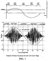
- Power line communication systems share the power line medium with various appliances that draw electric power from the power supply grid. These devices are some of the major sources of noise that affect the characteristics of power line channels. Several types of such devices generate noise that varies with the AC line cycle phase and the carrier frequencies. FIG. 1 shows an example wherein the noise around the zero crossing on the AC line cycle is lower by comparison to the noise at the peaks of the AC cycle. Devices like triaccontrolled dimmers turn on and off during each AC line cycle. These not only generate impulse noise but also change the channel frequency response. Further, several devices that use AC motors (e.g., vacuum cleaners, drills, etc.) generate noise that is also a function of the phase of the line cycle. The net effect is a time varying channel whose noise characteristics and frequency response depend on the AC line cycle phase.
- AC motors e.g., vacuum cleaners, drills, etc.
- the invention provides a method of operating in a network in which a plurality of stations communicate over a shared medium having a periodically varying channel according to Claim 1.
- the method includes determining a plurality of channel adaptations for communication between a pair of stations, and assigning a different one of the plurality of channel adaptations to each of a plurality of phase regions of the periodically varying channel.
- the channel adaptations for a particular phase region may be adapted to the channel in that phase region.
- the network may be a power line communication network
- the shared medium may be an AC power line (inside or outside a building and low, medium, or high voltage)
- the channel characteristics may vary with the phase of the AC line cycle.
- Channel adaptation may be synchronized to the periodically varying channel.
- Channel adaptation may be substantially unique between any pair of transmitter and receiver.
- Each station may have a channel adaptation facility that interacts with the channel facility at other stations.
- the channel adaptation facility may include a tone map generator for generating a tone map.
- the channel adaptation facility may include an indication of the start of the AC line cycle.
- the stations may exchange tone maps.
- the tone map generator may have the capability to generate multiple tone maps, with different tone maps being assigned to different phases regions of the AC line cycle. Different tone maps may be assigned to different regions of each half cycle of the AC line cycle, with each half cycle of the AC line cycle being treated as equivalent to the other half cycle for the purpose of channel adaptation.
- the AC line cycle may be divided into a plurality of substantially equal size phase regions, to which a different tone map may be assigned. Some of the substantially equal size phase regions may be assigned the same tone map.
- Associated with each tone map may be an indication of the tolerance of that tone map for use outside its boundaries.
- the indication of the start of an AC line cycle may include recognition of an AC line cycle zero crossing.
- the indication of the start of an AC line cycle may include recognition of an AC line cycle zero crossing followed by a rising signal.
- the indication of the start of an AC line cycle may include recognition of an AC line cycle zero crossing followed by a falling signal.
- the indication of the start of an AC line cycle may include recognition of a repeating feature in the AC line signal.
- the repeating feature in the AC line signal may include one or more of the following: a zero crossing, a peak in AC power amplitude, a peak or a minimum in noise amplitude.
- Time stamps may be transmitted between stations to aid synchronization of channel adaptation to the AC line cycle.
- the phase of the AC line cycle at a receiving station may be offset from the AC line cycle at a transmitting station, and information relating to the phase offset may be provided to the transmitting station so that the channel adaptation used by the transmitting station is synchronized to the AC line cycle at the receiving station.
- the information relating to the phase offset may include a zero crossing offset between the receiving and transmitting stations.
- the receiving station may determine the zero crossing offset, and transmit it to the transmitting station.
- the transmitting station may determine the zero crossing offset.
- One station in the network may track the AC line cycle zero crossing and transmit information on the time of the zero crossing to a plurality of stations on the network, and the plurality of stations may use the time of the zero crossing at the one station as their own local AC line cycle zero crossing.
- the AC line cycle zero crossing may be derived using virtual tracking, wherein a station uses its local clock along with knowledge of the AC line cycle frequency to track a virtual zero crossing.
- the number of tone map regions, boundaries of each region, and the tone map for each region may be determined based on periodically varying channel attenuation characteristics or on periodically varying local noise characteristics. If data is transmitted in packets that include at least one header and one payload, the tone map boundaries and length of the packets may be configured so that the payload of most packets is transmitted within one phase region so that a payload does not cross a boundary between tone maps. Or the tone map boundaries and length of the packets may be configured so that the payload of at least some packets is transmitted in two adjoining phase regions, so that a first portion of the payload is transmitted using one tone map and a second portion of the payload is transmitted using a second tone map.
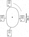
- the network configuration may include a plurality of stations, S 1 to S n , communicating over power line medium M. Because of the previously discussed channel variations between different locations on a power line network, medium M is unique between any pair of stations. Furthermore, the medium characteristics (which include attenuation, noise etc.,) show a periodic behavior.
- Each station S i has a channel adaptation function A i , that interacts with channel adaptation function at other stations to determine communication parameters that are referred to as tone maps.
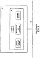
- FIG. 3 shows a typical station configuration.
- Each station S includes a channel adaptation function A, which includes a local clock, tone map generator, medium period start indicator (MPSI) and medium period start synchronization (MPSS).
- the tone map generator provides the tone maps that are used at various phase regions of the AC cycle. Each tone map specifies parameters including the set of carriers that are to be used, their modulation, and the forward error correction coding to be used.
- the local clock is a free running clock operating at a certain frequency. It is used as a time reference at each station.
- the medium period start indicator (MPSI) provides a reference for the start of the medium period for channel adaptation purposes.
- the medium period start synchronizer (MPSS) is used in implementations in which the MPSI of the transmitter and the MPSI of the receiver are offset from each other. The MPSS enables the tone map boundaries to be properly interpreted by the transmitter and the receiver.
- Stations exchange structured protocol entities called packets, the format of which is shown in FIG. 4 .
- the packet format allows for the exchange of tone maps, various fields required for medium period start synchronization (which can vary with the particular implementation), and regular data.
- the tone map generator uses knowledge of channel characteristics and the variation of those characteristics with the phase of the AC line cycle to derive multiple tone maps, which are assigned to different phase regions.
- the tone map generator uses the channel characteristics and their variation of those characteristics with the phase of the AC line cycle to determine the number of tone maps regions and the boundaries for each tone map region.
- Tone Map generator also generates tone maps for each of the tone map regions.
- the channel characteristics used by the tone map generator can include channel attenuation characteristics (or equivalently, the channel impulse response).
- the channel characteristics used by the tone map generator can also include local noise characteristics.
- the receiver generates multiple tone maps that can be used in various phase regions of each AC line cycle.
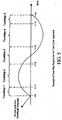
- FIG. 5 shows an example of such an implementation.
- the medium period start indicator (MPSI) tracks the rising edge of the AC zero crossing, and the channel estimation process produces five tone maps, one for each of five phase regions of the AC line cycle.
- ToneMap-1 is valid in regions (0, t1).
- ToneMap-2 is valid in regions (t1, t2).
- ToneMap-3 is valid in regions (t2, t3).
- ToneMap-4 is valid in region (t3, t4).
- ToneMap-5 is valid in region (t4, t5).
- the number of tone maps and their boundaries can be varied enormously from what is shown in FIG. 5 .
- FIG. 6 shows an example of the tone maps used in this implementation.
- the MPSI tracks the zero crossing of the AC line cycle, and the channel estimation process produces three tone maps. ToneMap-1 is valid in regions (0, t1) and (t3, t3+t1). ToneMap-2 is valid in regions (t1, t2) and (t3+t1, t3+t2). ToneMap-3 is valid in regions (t2, t3) and (t3+t2, t3+t3).
- the number of tone maps and their boundaries can be varied enormously from what is shown in FIG. 6 .
- Another implementation divides the AC line cycle into a fixed number of equal size phase regions.
- the channel adaptation process in this case results in tone maps for each of the equal size regions. It may turn out, that the same tone map is used in more than one of the regions.
- This approach can also use either full line cycle (e.g., FIG. 5 ) or half line cycle (e.g., FIG. 6 ) repetition of tone maps.
- FIG. 7 shows an example where each half line cycle is divided into five phase regions, and the channel adaptation process produces tone maps for each of the five regions.
- ToneMap-1 and ToneMap-2 might be the same.
- the MPSI tracks the zero crossings of the AC line cycle.
- the tone maps generated may contain a tolerance for their boundaries.
- a tone map may have a 100 ⁇ sec tolerance, which indicates that the tone map may be used up to a maximum of 100 ⁇ sec away from the actual boundary.
- a tone map may have a zero tolerance, indicating that the tone map may not be used beyond the boundaries provided.
- Another approach is to have tone maps boundaries overlap to indicate the tolerance.
- the transmitting station should ensure that proper tone maps are used at various phases of the AC line cycle.
- Some implementations that are considered preferred are presented below. These implementations can be used in packet-oriented networks, where MAC Protocol Data Units (MPDUs) are used to exchange data between stations.
- MPDUs MAC Protocol Data Units
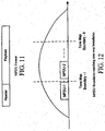
- FIG. 11 shows the MPDU format.
- MPDU contains header and payload fields.
- the header field contains information on MPDU transmission duration and tone map used for transmitting the payload fields.
- the payload field contains the data that is being exchanged.
- FIG. 12 shows an example with two tone map boundaries within a AC half line cycle. In this case, the length of MPDU-1 is chosen so that the payload duration does not cross the tone map boundary - 1. A similar procedure has to be used at the tone map boundary - II. Another approach is to allow for change of tone map within the MPDU payload.
- FIG. 13 shows an example of this preferred implementation. In this case, the MPDU header will indicate the location within the MPDU payload where a tone map change occurs. Thus, the MPDUs payload duration need not be aligned to the tone map boundaries.
- the AC line phase experienced by the transmitter may not be offset from the phase experienced by the receiver (Station B).
- This can result from various causes, including the two stations being on different phases of the AC power in the building, or inductive loading from an AC motor.
- a circuit at both the transmitter and receiver tracks the rising edge of the AC line cycle zero crossing, and information characterizing the offset of the zero crossings is transmitted to the other station.
- the transmitter (Station A in FIG. 9 ) may insert the offset of the current time from AC zero crossing (T A,zc,Offset ) just before transmitting a packet,
- the receiver may then store its local AC zero crossing offset (T B,zc,Offset ) upon reception of the packet.
- the difference between the local and received zero crossing offsets (T B,zc,Offset -T A,zc,Offset ) provides the relative phase offset of the receiver from the transmitter.
- Information relating to the phase offset can be sent back to the transmitter in another packet so that tone maps used by the transmitter can be synchronized to the zero crossing at the receiver.
- the transmitter could determine the offset, by itself, based on zero crossing offset information received from the receiver.
- Another implementation uses a centralized approach, wherein one station (referred to as the synchronizer station) in the network has a circuit for tracking the rising edge of the AC line cycle zero crossing.
- the packet format for this implementation enables the transmission of the zero crossing offset between the synchronizer station and all other stations in the network (e.g., by broadcast to all stations in the network and/or unicast to each individual station). All stations in the network track the AC line cycle zero crossing of the synchronizer station and use it as their own local AC line cycle zero crossing.
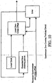
- FIG. 10 shows an example of a circuit that can be used to track the synchronizer station zero crossing. This circuit computes the expected zero crossing period based on a feedback loop. Tone map boundaries of all stations in the network are synchronized as all stations track the same synchronizer station zero crossing.
- a circuit tracking the falling edge of the AC Line cycle zero crossing can be used.
- a circuit tracking the zero crossing (irrespective of whether it is the rising or falling edge) of the AC line cycle can be used.
- a circuit tracking a certain phase for example, a peak of one polarity of the other
- a circuit that tracks the synchronous noise on the line cycle is another of the many possibilities.
- the physical tracking of the zero crossing can also be replaced by virtual tracking.
- a station uses its local clock along with knowledge of the AC line cycle frequency to track a virtual zero crossing. If the local clocks are not tightly synchronized, stations may exchange time stamps to obtain tight synchronization.
- Time stamps of various types can be sent while channel adaptation is in progress. or during regular transmissions.
Landscapes
- Engineering & Computer Science (AREA)
- Signal Processing (AREA)
- Computer Networks & Wireless Communication (AREA)
- Power Engineering (AREA)
- Cable Transmission Systems, Equalization Of Radio And Reduction Of Echo (AREA)
Description
- Communication systems are designed to reliably transfer information using the underlying physical medium. Well-known communication systems like Ethernet use special wiring (e.g., Cat 5 cable) for exchanging information. Such systems, by design, allow all connected stations to exchange data at a fixed data rate. With the increasing need for ubiquitous exchange of information, a new class of no-new-wire systems has emerged. Such systems use existing infrastructure to exchange information. Power line communication systems are one example of such systems.
- Power line communication systems use existing AC wiring to exchange information. Owing to their being designed for much lower frequency transmissions, AC wiring provides varying channel characteristics at the higher frequencies used for data transmission (e.g., depending on the wiring used and the actual layout). To maximize the data rate between various links, stations need to adjust their transmission parameters dynamically in both time and frequency. This process is called channel adaptation. Channel adaptation results in a set of transmission parameters (referred to as tone maps in this document) that can be used on each link. Tone maps include such parameters as the frequencies used, their modulation, and the forward error correction (FEC) used. In high-speed power line communication systems, good channel adaptation is critical to providing high data rates on all links.
-
WO 02/51089 - The article entitled, "Digital Signal Processing For Multi-Carrier Data Transmission On Phase-Controlled Power Lines With Nonlinearities", G. Dickmann et al, IEEE, , discloses a method involving transmitting data blockwise inside intervals where the channel is linear. This includes restricting transmission to only one interval Ir of length Tr = T/2.1/6 per line half-period.
- We have discovered that higher data rates can be achieved in power line communication systems by taking into account the fact that the noise and/or the frequency response of the power line channel between any pair of stations depends on the AC line cycle phase.
- Power line communication systems share the power line medium with various appliances that draw electric power from the power supply grid. These devices are some of the major sources of noise that affect the characteristics of power line channels. Several types of such devices generate noise that varies with the AC line cycle phase and the carrier frequencies.
FIG. 1 shows an example wherein the noise around the zero crossing on the AC line cycle is lower by comparison to the noise at the peaks of the AC cycle. Devices like triaccontrolled dimmers turn on and off during each AC line cycle. These not only generate impulse noise but also change the channel frequency response. Further, several devices that use AC motors (e.g., vacuum cleaners, drills, etc.) generate noise that is also a function of the phase of the line cycle. The net effect is a time varying channel whose noise characteristics and frequency response depend on the AC line cycle phase. - The invention provides a method of operating in a network in which a plurality of stations communicate over a shared medium having a periodically varying channel according to
Claim 1. The method includes determining a plurality of channel adaptations for communication between a pair of stations, and assigning a different one of the plurality of channel adaptations to each of a plurality of phase regions of the periodically varying channel. - In preferred implementations, one or more of the following features may be incorporated. The channel adaptations for a particular phase region may be adapted to the channel in that phase region. The network may be a power line communication network, the shared medium may be an AC power line (inside or outside a building and low, medium, or high voltage), and the channel characteristics may vary with the phase of the AC line cycle. Channel adaptation may be synchronized to the periodically varying channel. Channel adaptation may be substantially unique between any pair of transmitter and receiver. Each station may have a channel adaptation facility that interacts with the channel facility at other stations. The channel adaptation facility may include a tone map generator for generating a tone map. The channel adaptation facility may include an indication of the start of the AC line cycle. The stations may exchange tone maps. The tone map generator may have the capability to generate multiple tone maps, with different tone maps being assigned to different phases regions of the AC line cycle. Different tone maps may be assigned to different regions of each half cycle of the AC line cycle, with each half cycle of the AC line cycle being treated as equivalent to the other half cycle for the purpose of channel adaptation. The AC line cycle may be divided into a plurality of substantially equal size phase regions, to which a different tone map may be assigned. Some of the substantially equal size phase regions may be assigned the same tone map. Associated with each tone map may be an indication of the tolerance of that tone map for use outside its boundaries. The indication of the start of an AC line cycle may include recognition of an AC line cycle zero crossing. The indication of the start of an AC line cycle may include recognition of an AC line cycle zero crossing followed by a rising signal. The indication of the start of an AC line cycle may include recognition of an AC line cycle zero crossing followed by a falling signal. The indication of the start of an AC line cycle may include recognition of a repeating feature in the AC line signal. The repeating feature in the AC line signal may include one or more of the following: a zero crossing, a peak in AC power amplitude, a peak or a minimum in noise amplitude. Time stamps may be transmitted between stations to aid synchronization of channel adaptation to the AC line cycle. The phase of the AC line cycle at a receiving station may be offset from the AC line cycle at a transmitting station, and information relating to the phase offset may be provided to the transmitting station so that the channel adaptation used by the transmitting station is synchronized to the AC line cycle at the receiving station. The information relating to the phase offset may include a zero crossing offset between the receiving and transmitting stations. The receiving station may determine the zero crossing offset, and transmit it to the transmitting station. The transmitting station may determine the zero crossing offset. One station in the network may track the AC line cycle zero crossing and transmit information on the time of the zero crossing to a plurality of stations on the network, and the plurality of stations may use the time of the zero crossing at the one station as their own local AC line cycle zero crossing. The AC line cycle zero crossing may be derived using virtual tracking, wherein a station uses its local clock along with knowledge of the AC line cycle frequency to track a virtual zero crossing. The number of tone map regions, boundaries of each region, and the tone map for each region may be determined based on periodically varying channel attenuation characteristics or on periodically varying local noise characteristics. If data is transmitted in packets that include at least one header and one payload, the tone map boundaries and length of the packets may be configured so that the payload of most packets is transmitted within one phase region so that a payload does not cross a boundary between tone maps. Or the tone map boundaries and length of the packets may be configured so that the payload of at least some packets is transmitted in two adjoining phase regions, so that a first portion of the payload is transmitted using one tone map and a second portion of the payload is transmitted using a second tone map.
- Among the many advantages of the invention (some of which may be achieved only in some of its implementations) are the following. It enables stations to operate reliability and at higher data rates under various power line environments. It provides a channel adaptation mechanism that can be used in power line communication systems as well as other media that are affected by periodically varying channel impairments. It can provide a higher level of guaranteed quality of service (QoS).
-
-
FIG. 1 shows an example of the variation in noise with AC line cycle phase. -
FIG. 2 is a schematic of a power line network configuration. -
FIG. 3 is a block diagram of the configuration of a station on the power line network. -
FIG. 4 shows the format of a packet sent over the network. -
FIG. 5 shows an implementation in which a different tone maps may be assigned to each of five different phase regions of the AC line cycle. -
FIG. 6 shows an implementation in which a different tone map may be assigned to each of three different phase regions of each half period of the AC line cycle. -
FIG. 7 shows an implementation in which a different tone map may be assigned to each of five equal-size phase regions of each half period of the AC line cycle. -
FIG. 8 shows an example in which the phase of the AC line cycle is offset between the transmitting and receiving stations. -
FIG. 9 illustrates the use of transmitter zero cross time stamps to compute the phase offset between stations. -
FIG. 10 is a block diagram of a synchronizer zero crossing tracking circuit that can be used in some implementations. -
FIG. 11 shows the MPDU format. -
FIG. 12 shows an example where MPDU boundaries matching tone map boundaries. -
FIG 13 shows an example where MPDU boundaries cross tone map boundaries. - There are a great many possible implementations of the invention, too many to describe herein. Some possible implementations that are presently preferred are described below. It cannot be emphasized too strongly, however, that these are descriptions of implementations of the invention, and not descriptions of the invention, which is not limited to the detailed implementations described in this section but is described in broader terms in the claims.
- As shown in
FIG. 2 , the network configuration may include a plurality of stations, S1 to Sn, communicating over power line medium M. Because of the previously discussed channel variations between different locations on a power line network, medium M is unique between any pair of stations. Furthermore, the medium characteristics (which include attenuation, noise etc.,) show a periodic behavior. Each station Si has a channel adaptation function Ai, that interacts with channel adaptation function at other stations to determine communication parameters that are referred to as tone maps. -
FIG. 3 shows a typical station configuration. Each station S includes a channel adaptation function A, which includes a local clock, tone map generator, medium period start indicator (MPSI) and medium period start synchronization (MPSS). The tone map generator provides the tone maps that are used at various phase regions of the AC cycle. Each tone map specifies parameters including the set of carriers that are to be used, their modulation, and the forward error correction coding to be used. The local clock is a free running clock operating at a certain frequency. It is used as a time reference at each station. The medium period start indicator (MPSI) provides a reference for the start of the medium period for channel adaptation purposes. The medium period start synchronizer (MPSS) is used in implementations in which the MPSI of the transmitter and the MPSI of the receiver are offset from each other. The MPSS enables the tone map boundaries to be properly interpreted by the transmitter and the receiver. - Stations exchange structured protocol entities called packets, the format of which is shown in
FIG. 4 . The packet format allows for the exchange of tone maps, various fields required for medium period start synchronization (which can vary with the particular implementation), and regular data. - Various implementations of the tone map generator are possible. In general terms, the tone map generator uses knowledge of channel characteristics and the variation of those characteristics with the phase of the AC line cycle to derive multiple tone maps, which are assigned to different phase regions. The tone map generator uses the channel characteristics and their variation of those characteristics with the phase of the AC line cycle to determine the number of tone maps regions and the boundaries for each tone map region. Tone Map generator also generates tone maps for each of the tone map regions. The channel characteristics used by the tone map generator can include channel attenuation characteristics (or equivalently, the channel impulse response). The channel characteristics used by the tone map generator can also include local noise characteristics.
- In one implementation, the receiver generates multiple tone maps that can be used in various phase regions of each AC line cycle.
FIG. 5 shows an example of such an implementation. In this example, the medium period start indicator (MPSI) tracks the rising edge of the AC zero crossing, and the channel estimation process produces five tone maps, one for each of five phase regions of the AC line cycle. ToneMap-1 is valid in regions (0, t1). ToneMap-2 is valid in regions (t1, t2). ToneMap-3 is valid in regions (t2, t3). ToneMap-4 is valid in region (t3, t4). ToneMap-5 is valid in region (t4, t5). The number of tone maps and their boundaries can be varied enormously from what is shown inFIG. 5 . - Another implementation allows the receiver to generate multiple tone maps that can be used in various phase regions of each AC half line cycle. But in this implementation, both the positive and negative halves of the AC line cycle are treated as equivalent. The two halves of the line cycle are very often substantially identical (except for being of opposite phase) in most PLC networks.
FIG. 6 shows an example of the tone maps used in this implementation. The MPSI tracks the zero crossing of the AC line cycle, and the channel estimation process produces three tone maps. ToneMap-1 is valid in regions (0, t1) and (t3, t3+t1). ToneMap-2 is valid in regions (t1, t2) and (t3+t1, t3+t2). ToneMap-3 is valid in regions (t2, t3) and (t3+t2, t3+t3). As with the first implementation example, the number of tone maps and their boundaries can be varied enormously from what is shown inFIG. 6 . - Another implementation divides the AC line cycle into a fixed number of equal size phase regions. The channel adaptation process in this case results in tone maps for each of the equal size regions. It may turn out, that the same tone map is used in more than one of the regions. This approach can also use either full line cycle (e.g.,
FIG. 5 ) or half line cycle (e.g.,FIG. 6 ) repetition of tone maps.FIG. 7 shows an example where each half line cycle is divided into five phase regions, and the channel adaptation process produces tone maps for each of the five regions. Depending on the channel conditions, it is possible that the same tone map is used in multiple regions. For example, ToneMap-1 and ToneMap-2 might be the same. In this example, the MPSI tracks the zero crossings of the AC line cycle. - In all the above implementations, the tone maps generated may contain a tolerance for their boundaries. For example, a tone map may have a 100 µsec tolerance, which indicates that the tone map may be used up to a maximum of 100 µsec away from the actual boundary. Alternatively, a tone map may have a zero tolerance, indicating that the tone map may not be used beyond the boundaries provided. Another approach is to have tone maps boundaries overlap to indicate the tolerance. The transmitting station should ensure that proper tone maps are used at various phases of the AC line cycle. Several approaches can be used by the transmitter to maintain tone map boundaries. Some implementations that are considered preferred are presented below. These implementations can be used in packet-oriented networks, where MAC Protocol Data Units (MPDUs) are used to exchange data between stations.
FIG. 11 shows the MPDU format. MPDU contains header and payload fields. The header field contains information on MPDU transmission duration and tone map used for transmitting the payload fields. The payload field contains the data that is being exchanged. - One preferred implementation is to align the MPDU payload boundaries so that they do not cross tone map boundaries.
FIG. 12 shows an example with two tone map boundaries within a AC half line cycle. In this case, the length of MPDU-1 is chosen so that the payload duration does not cross the tone map boundary - 1. A similar procedure has to be used at the tone map boundary - II. Another approach is to allow for change of tone map within the MPDU payload.FIG. 13 shows an example of this preferred implementation. In this case, the MPDU header will indicate the location within the MPDU payload where a tone map change occurs. Thus, the MPDUs payload duration need not be aligned to the tone map boundaries. - As shown in
FIG. 8 , the AC line phase experienced by the transmitter (Station A) may not be offset from the phase experienced by the receiver (Station B). This can result from various causes, including the two stations being on different phases of the AC power in the building, or inductive loading from an AC motor. Generally, it is desirable that the tone maps used be prescribed by the phase of the receiver. For that to happen, the transmitter must be made aware of the relative phase offset of the receiver from the transmitter. A wide variety of implementations are possible for achieving this result. - One implementation uses knowledge of the AC zero crossing at each station. A circuit at both the transmitter and receiver, tracks the rising edge of the AC line cycle zero crossing, and information characterizing the offset of the zero crossings is transmitted to the other station. For example, the transmitter (Station A in
FIG. 9 ) may insert the offset of the current time from AC zero crossing (TA,zc,Offset) just before transmitting a packet, The receiver may then store its local AC zero crossing offset (TB,zc,Offset) upon reception of the packet. The difference between the local and received zero crossing offsets (TB,zc,Offset-TA,zc,Offset) provides the relative phase offset of the receiver from the transmitter. Information relating to the phase offset can be sent back to the transmitter in another packet so that tone maps used by the transmitter can be synchronized to the zero crossing at the receiver. Alternatively, the transmitter could determine the offset, by itself, based on zero crossing offset information received from the receiver. - Another implementation uses a centralized approach, wherein one station (referred to as the synchronizer station) in the network has a circuit for tracking the rising edge of the AC line cycle zero crossing. The packet format for this implementation enables the transmission of the zero crossing offset between the synchronizer station and all other stations in the network (e.g., by broadcast to all stations in the network and/or unicast to each individual station). All stations in the network track the AC line cycle zero crossing of the synchronizer station and use it as their own local AC line cycle zero crossing.
FIG. 10 shows an example of a circuit that can be used to track the synchronizer station zero crossing. This circuit computes the expected zero crossing period based on a feedback loop. Tone map boundaries of all stations in the network are synchronized as all stations track the same synchronizer station zero crossing. - Various alternatives to tracking the rising edge of the AC line cycle zero crossing are possible. For example, a circuit tracking the falling edge of the AC Line cycle zero crossing can be used. Alternatively, a circuit tracking the zero crossing (irrespective of whether it is the rising or falling edge) of the AC line cycle can be used. And a circuit tracking a certain phase (for example, a peak of one polarity of the other) can be tracked in place of zero crossings. Another of the many possibilities is a circuit that tracks the synchronous noise on the line cycle.
- The physical tracking of the zero crossing can also be replaced by virtual tracking. To use virtual tracking, a station uses its local clock along with knowledge of the AC line cycle frequency to track a virtual zero crossing. If the local clocks are not tightly synchronized, stations may exchange time stamps to obtain tight synchronization.
- Time stamps of various types can be sent while channel adaptation is in progress. or during regular transmissions.
- Many other implementations of the invention other than those described above are within the invention, which is defined by the following claims.
Claims (29)
- A method of operating in a network in which a plurality of stations (S1-Sn) communicate over a shared medium (M) having a periodically varying channel, comprising
determining a plurality of channel adaptations for communication between a pair of stations;assigning a different one of the plurality of channel adaptations to each of a plurality of phase regions of the periodically varying channel,wherein the plurality of channel adaptations include communication parameters specifying at least a plurality of frequencies used for communicating between the pair of stationsand respective modulations for the specified frequencies. - The method of claim 1 wherein the plurality of channel adaptations for a particular phase region are adapted to the channel in that phase region.
- The method of claim 2 wherein the network is a power line communication network, the shared medium (M) is an AC power line, and channel characteristics vary with the phase of the AC line cycle.
- The method of claim 1 where channel adaptation is substantially unique between any pair of transmitter and receiver.
- The method of claim 1 wherein each station has a channel adaptation facility (A1-An) that interacts with the channel adaptation facility at other stations.
- The method of claim 5 wherein the channel adaptation facility (A1-An) comprises a tone map generator for generating a tone map (ToneMap-1 - ToneMap-5; ToneMap-1 - ToneMap-3; TM-1 - TM-5).
- The method of claim 6 wherein the channel adaptation facility (A1-Art) comprises an indication of the start of an AC line cycle.
- The method of claim 6 wherein the stations (S1-Sn) exchange tone maps (ToneMap-1 ToneMap-5; ToneMap-1 - ToneMap-3; TM-1 - TM-5).
- The method of claim 6 wherein the tone map generator has the capability to generate multiple tone maps (ToneMap-1 - ToneMap-5; ToneMap-1 - ToneMap-3; TM- 1 - TM-5), with different tone maps being assigned to different phases regions of the AC line cycle.
- The method of claim 9 wherein different tone maps (ToneMap-1 - ToneMap-3) are assigned to different regions of each half cycle of the AC line cycle, with each half cycle of the AC line cycle being treated as equivalent to the other half cycle for the purpose of channel adaptation.
- The method of claim 9 wherein the AC line cycle is divided into a plurality of substantially equal size phase regions, to which a different tone map (TM-1 - TM-5) may be assigned.
- The method of claim 11 wherein some of the substantially equal size phase regions are assigned the same tone map (TM-1 - TM-5).
- The method of claim 6 wherein associated with each tone map (ToneMap-1 - ToneMap-5; ToneMap-1 - ToneMap-3; TM-1 - TM-5) is an indication of the tolerance of that tone map for use outside its boundaries.
- The method of claim 7 wherein the indication of the start of the AC line cycle comprises recognition of an AC line cycle zero crossing.
- The method of claim 7 wherein the indication of the start of the AC line cycle comprises recognition of an AC line cycle zero crossing followed by a rising signal.
- The method of claim 7 wherein the indication of the start of the AC line cycle comprises recognition of an AC line cycle zero crossing followed by a falling signal.
- The method of claim 7 wherein the indication of the start of the AC line cycle comprises recognition of a repeating feature in an AC line signal.
- The method of claim 17 wherein the repeating feature in the AC line signal comprises one or more of the following: a zero crossing, a peak in AC power amplitude, a peak or a minimum in noise amplitude.
- The method of claim 1 wherein time stamps are transmitted between stations (S1-Sn) to aid synchronization of channel adaptation.
- The method of claim 3 wherein the phase of the AC line cycle at a receiving station is offset from the AC line cycle at a transmitting station, and information relating
to the phase offset is provided to the transmitting station so that the channel adaptation used by the transmitting station is synchronized to the AC line cycle at the receiving station. - The method of claim 20 wherein the information relating to the phase offset comprises a zero crossing offset between the receiving and transmitting stations.
- The method of claim 21 wherein the receiving station determines the zero crossing offset, and transmits it to the transmitting station.
- The method of claim 22 wherein the transmitting station determines the zero crossing offset.
- The method of claim 14 wherein one station in the network tracks the AC line cycle Zero crossing and transmits information on a time of the zero crossing to a plurality of stations on the network, and wherein the plurality of stations (S1-Sn) use the time of the zero crossing at the one station as their own local AC line cycle zero crossing.
- The method of claim 14 wherein the AC line cycle zero crossing is derived using virtual tracking, wherein a station (S1-Sn) uses its local clock along with knowledge of the AC line cycle frequency to track a virtual zero crossing.
- The method of claim 9 wherein the number of tone map regions, boundaries of each region, and the tone map (ToneMap-1 - ToneMap-5; ToneMap-1 ToneMap-3; TM-1 TM-5) for-each region are determined based on periodically varying channel attenuation characteristics.
- The method of claim 9 wherein the number of tone map regions, boundaries of each region, and the tone map (ToneMap-1 - ToneMap-5; ToneMap-1 - ToneMap-3; TM-1 - TM-5) for each region are determined based on periodically varying local noise characteristics.
- The method of claim 9 wherein data is transmitted in packets that include at least one header and one payload, and wherein the tone map boundaries arid length of the packets are configured so that the payload of most packets is transmitted within one phase region so that the payload does not cross a boundary between tone maps (ToneMap-1 ToneMap-5; ToneMap-1 - ToneMap-3; TM-1 - TM-5).
- The method of claim 9 wherein data is transmitted in packets that include at least one header and one payload, and wherein the tone map boundaries and length of the packets are configured so that the payload of at least some packets is transmitted in two adjoining phase regions, so that a first portion of the payload is transmitted using one tone map and a second portion of the payload is transmitted using a second tone map.
Applications Claiming Priority (2)
| Application Number | Priority Date | Filing Date | Title |
|---|---|---|---|
| US787544 | 1985-10-15 | ||
| US10/787,544 US7715425B2 (en) | 2004-02-26 | 2004-02-26 | Channel adaptation synchronized to periodically varying channel |
Publications (3)
| Publication Number | Publication Date |
|---|---|
| EP1569358A2 EP1569358A2 (en) | 2005-08-31 |
| EP1569358A3 EP1569358A3 (en) | 2005-10-12 |
| EP1569358B1 true EP1569358B1 (en) | 2016-06-29 |
Family
ID=34750512
Family Applications (1)
| Application Number | Title | Priority Date | Filing Date |
|---|---|---|---|
| EP05251166.4A Expired - Lifetime EP1569358B1 (en) | 2004-02-26 | 2005-02-28 | Channel adaptation synchronized to periodically varying channel |
Country Status (4)
| Country | Link |
|---|---|
| US (1) | US7715425B2 (en) |
| EP (1) | EP1569358B1 (en) |
| JP (1) | JP2005253076A (en) |
| CN (1) | CN1722629A (en) |
Families Citing this family (35)
| Publication number | Priority date | Publication date | Assignee | Title |
|---|---|---|---|---|
| EP1554848A4 (en) * | 2002-10-21 | 2010-03-03 | Intellon Corp | Contention-free access intervals on a csma network |
| US7684568B2 (en) * | 2003-11-24 | 2010-03-23 | Intellon Corporation | Encrypting data in a communication network |
| US8090857B2 (en) | 2003-11-24 | 2012-01-03 | Qualcomm Atheros, Inc. | Medium access control layer that encapsulates data from a plurality of received data units into a plurality of independently transmittable blocks |
| US8571026B2 (en) * | 2004-05-12 | 2013-10-29 | Stmicroelectronics, Inc. | System and method for an intelligent load center with integrated powerline communications network switching and network management capabilities |
| JP5052742B2 (en) | 2004-07-22 | 2012-10-17 | パナソニック株式会社 | Transmitting apparatus and communication system using the same |
| DE102004044957B4 (en) * | 2004-09-16 | 2007-04-19 | Infineon Technologies Ag | Medium access control unit, mobile radio device and method for mapping by means of a mobile radio device data to be transmitted |
| JP4852246B2 (en) * | 2005-01-04 | 2012-01-11 | パナソニック株式会社 | COMMUNICATION DEVICE, INTEGRATED CIRCUIT, AND COMMUNICATION METHOD |
| US7756942B2 (en) * | 2005-07-21 | 2010-07-13 | Sony Corporation | System and method for establishing master component in multiple home networks |
| US7822059B2 (en) | 2005-07-27 | 2010-10-26 | Atheros Communications, Inc. | Managing contention-free time allocations in a network |
| US7729372B2 (en) * | 2005-07-27 | 2010-06-01 | Sharp Corporation | Communicating in a network that includes a medium having varying transmission characteristics |
| US7558294B2 (en) * | 2005-07-27 | 2009-07-07 | Intellon Corporation | Time synchronization in a network |
| US8175190B2 (en) | 2005-07-27 | 2012-05-08 | Qualcomm Atheros, Inc. | Managing spectra of modulated signals in a communication network |
| JP4635947B2 (en) * | 2005-10-12 | 2011-02-23 | パナソニック株式会社 | Power line communication device, integrated circuit, and power line communication method |
| US7876717B2 (en) * | 2005-12-09 | 2011-01-25 | Sony Corporation | System and method for providing access in powerline communications (PLC) network |
| KR101217628B1 (en) * | 2006-02-16 | 2013-01-02 | 삼성전자주식회사 | Method for packet aggregation in power line communication network and apparatus therefor |
| DE102006049507B4 (en) * | 2006-10-17 | 2016-05-25 | Sew-Eurodrive Gmbh & Co Kg | Plant and method for operating a plant |
| JP4877004B2 (en) * | 2007-03-27 | 2012-02-15 | 東京電力株式会社 | Wireless sensor network power saving system |
| KR101484798B1 (en) | 2007-05-10 | 2015-01-28 | 퀄컴 인코포레이티드 | Managing Distributed Access to Shared Media |
| JP5448359B2 (en) * | 2007-05-30 | 2014-03-19 | パナソニック株式会社 | Power line communication method, power line communication apparatus, and power line communication system |
| US20080298382A1 (en) * | 2007-05-31 | 2008-12-04 | Matsushita Electric Industrial Co., Ltd. | Method, apparatus and system for progressive refinementof channel estimation to increase network data throughput and reliability |
| JP5121054B2 (en) * | 2007-06-01 | 2013-01-16 | パナソニック株式会社 | COMMUNICATION METHOD, COMMUNICATION DEVICE, AND COMMUNICATION SYSTEM |
| US9521090B2 (en) * | 2007-06-04 | 2016-12-13 | Qualcomm Incorporated | Authorizing stations into a centrally managed network |
| JP5152967B2 (en) | 2007-10-12 | 2013-02-27 | パナソニック株式会社 | COMMUNICATION METHOD, COMMUNICATION DEVICE, AND COMMUNICATION SYSTEM, |
| TW200934154A (en) * | 2007-12-28 | 2009-08-01 | Panasonic Corp | Communication device and communication system |
| JP2011524724A (en) * | 2008-06-16 | 2011-09-01 | ダブリュ. ヤング、ローレンス | Managing coexistence between signaling protocols on shared media |
| US8296494B1 (en) * | 2010-03-31 | 2012-10-23 | The Boeing Company | Expanded electronic bus communication capacity |
| JP5678171B2 (en) | 2010-04-12 | 2015-02-25 | クゥアルコム・インコーポレイテッドQualcomm Incorporated | Channel estimation for low overhead communication in networks |
| JPWO2012014502A1 (en) * | 2010-07-30 | 2013-09-12 | パナソニック株式会社 | COMMUNICATION METHOD, COMMUNICATION DEVICE, AND COMMUNICATION FRAME GENERATION METHOD |
| US8761276B2 (en) | 2010-12-29 | 2014-06-24 | Hong Kong Applied Science and Technology Research Institute Company Limited | OFDM symbol structure for power line communication |
| US8891605B2 (en) | 2013-03-13 | 2014-11-18 | Qualcomm Incorporated | Variable line cycle adaptation for powerline communications |
| US9537641B2 (en) * | 2013-05-30 | 2017-01-03 | Qualcomm Incorporated | Channel adaptation to compensate for interference from neighbor powerline communication networks |
| CN110278008B (en) * | 2018-03-16 | 2021-05-04 | 华为技术有限公司 | A power line communication method, device and computer storage medium |
| US11811273B2 (en) | 2018-06-01 | 2023-11-07 | Franklin Electric Co., Inc. | Motor protection device and method for protecting a motor |
| US10454267B1 (en) | 2018-06-01 | 2019-10-22 | Franklin Electric Co., Inc. | Motor protection device and method for protecting a motor |
| CN110719223B (en) * | 2019-09-16 | 2020-08-11 | 清华大学 | Method and system for cooperative self-adaptive adjustment of detection period |
Family Cites Families (189)
| Publication number | Priority date | Publication date | Assignee | Title |
|---|---|---|---|---|
| US3806885A (en) | 1972-12-29 | 1974-04-23 | Ibm | Polling mechanism for transferring control from one data processing system or subsystem to another |
| US4032884A (en) | 1976-02-24 | 1977-06-28 | The United States Of America As Represented By The Secretary Of The Army | Adaptive trunk data transmission system |
| US4593280A (en) | 1982-03-05 | 1986-06-03 | Burroughs Corporation | Write token regeneration in a timed token ring |
| US4569044A (en) | 1983-05-25 | 1986-02-04 | Case Western Reserve University | Distributed data communication system |
| US4581734A (en) | 1984-02-14 | 1986-04-08 | Rosemount Inc. | Multipriority communication system |
| US4677612A (en) | 1984-02-14 | 1987-06-30 | Rosemount Inc. | Communication system with subdivided transmission cycles |
| DE3413144A1 (en) | 1984-04-07 | 1985-10-17 | Licentia Patent-Verwaltungs-Gmbh, 6000 Frankfurt | Digital local communications system with the logical structure of a loop |
| US4630261A (en) | 1984-07-30 | 1986-12-16 | International Business Machines Corp. | Integrated buffer management and signaling technique |
| US4682324A (en) | 1985-10-11 | 1987-07-21 | General Electric Company | Implicit preemptive lan |
| GB8606217D0 (en) | 1986-03-13 | 1986-04-16 | Univ Strathclyde | Local area network priority control system |
| US4720850A (en) | 1986-03-14 | 1988-01-19 | American Telephone And Telegraph Company At&T Bell Laboratories | Communication system control arrangement |
| US5003539A (en) | 1986-04-11 | 1991-03-26 | Ampex Corporation | Apparatus and method for encoding and decoding attribute data into error checking symbols of main data |
| JPS62239641A (en) | 1986-04-11 | 1987-10-20 | Hitachi Ltd | Broadcast communication method |
| JPS6336622A (en) * | 1986-07-31 | 1988-02-17 | Nec Home Electronics Ltd | Method and apparatus for spread spectrum power line carrier communication |
| US4726018A (en) | 1986-08-25 | 1988-02-16 | International Business Machines Corporation | Method of providing priority access to a transmission communication ring |
| EP0313707B1 (en) | 1987-10-30 | 1993-03-31 | International Business Machines Corporation | Data integrity securing means |
| GB2217152A (en) | 1988-02-10 | 1989-10-18 | Plessey Co Plc | Data packet switching |
| US5001472A (en) | 1988-02-11 | 1991-03-19 | Datapoint Corporation | Uneven token distribution technique for token based local area network |
| US4881241A (en) | 1988-02-24 | 1989-11-14 | Centre National D'etudes Des Telecommunications | Method and installation for digital communication, particularly between and toward moving vehicles |
| US5105423A (en) | 1988-05-17 | 1992-04-14 | Ricoh Company, Ltd. | Digital transmission device having an error correction mode and method for shifting down a data transmission rate |
| US5121396A (en) | 1988-10-27 | 1992-06-09 | International Business Machines Corp. | Preservation of crc integrity upon intentional data alteration during message transmission |
| JPH02172332A (en) * | 1988-12-26 | 1990-07-03 | Nec Home Electron Ltd | Reception signal equalizer for spread spectrum communication system |
| US5140584A (en) | 1989-03-01 | 1992-08-18 | Kabushiki Kaisha Toshiba | Packet communication system and method of controlling same |
| US5081678A (en) | 1989-06-28 | 1992-01-14 | Digital Equipment Corporation | Method for utilizing an encrypted key as a key identifier in a data packet in a computer network |
| US5214646A (en) | 1990-01-31 | 1993-05-25 | Amnon Yacoby | System and method for interconnecting local area networks |
| FR2658017B1 (en) | 1990-02-06 | 1992-06-05 | France Etat | METHOD FOR BROADCASTING DIGITAL DATA, ESPECIALLY FOR BROADBAND BROADCASTING TO MOBILES, WITH TIME-FREQUENCY INTERLACING AND ASSISTING THE ACQUISITION OF AUTOMATIC FREQUENCY CONTROL, AND CORRESPONDING RECEIVER. |
| FR2658016B1 (en) | 1990-02-06 | 1994-01-21 | Etat Francais Cnet | METHOD FOR BROADCASTING DIGITAL DATA, ESPECIALLY FOR BROADBAND BROADCASTING TO MOBILES, WITH TIME-FREQUENCY INTERLACING AND CONSISTENT DEMODULATION, AND CORRESPONDING RECEIVER. |
| FR2660131B1 (en) | 1990-03-23 | 1992-06-19 | France Etat | DEVICE FOR TRANSMITTING DIGITAL DATA WITH AT LEAST TWO LEVELS OF PROTECTION, AND CORRESPONDING RECEPTION DEVICE. |
| JPH05505290A (en) | 1990-03-30 | 1993-08-05 | エヌディーエス・リミテッド | Transmission and reception in hostile environments with interference |
| EP0453863A2 (en) | 1990-04-27 | 1991-10-30 | National Semiconductor Corporation | Methods and apparatus for implementing a media access control/host system interface |
| CA2018301A1 (en) | 1990-06-05 | 1991-12-05 | David P. G. Schenkel | Packet communication system and method of clearing communication bus |
| FR2671923B1 (en) | 1991-01-17 | 1993-04-16 | France Etat | DEVICE FOR CONSISTENT DEMODULATION OF DIGITAL DATA INTERLACED IN TIME AND IN FREQUENCY, WITH ESTIMATION OF THE FREQUENTIAL RESPONSE OF THE TRANSMISSION AND THRESHOLD CHANNEL, AND CORRESPONDING TRANSMITTER. |
| US5280480A (en) | 1991-02-21 | 1994-01-18 | International Business Machines Corporation | Source routing transparent bridge |
| US5339313A (en) | 1991-06-28 | 1994-08-16 | Digital Equipment Corporation | Method and apparatus for traffic congestion control in a communication network bridge device |
| US5231634B1 (en) | 1991-12-18 | 1996-04-02 | Proxim Inc | Medium access protocol for wireless lans |
| US5555268A (en) | 1994-01-24 | 1996-09-10 | Fattouche; Michel | Multicode direct sequence spread spectrum |
| US5896561A (en) | 1992-04-06 | 1999-04-20 | Intermec Ip Corp. | Communication network having a dormant polling protocol |
| FR2690029B1 (en) | 1992-04-08 | 1995-03-31 | France Telecom | Method for transmitting digital paging data, and corresponding paging receiver. |
| US5426646A (en) | 1992-06-25 | 1995-06-20 | The United States Of America As Represented By The Secretary Of The Navy | Instantaneous bit-error-rate meter |
| JPH0677963A (en) | 1992-07-07 | 1994-03-18 | Hitachi Ltd | Communication system and terminal equipment |
| DE69322322T2 (en) | 1992-07-08 | 1999-06-17 | Koninklijke Philips Electronics N.V., Eindhoven | Chained coding for OFDM transmission |
| US5343473A (en) | 1992-08-07 | 1994-08-30 | International Business Machines Corporation | Method of determining whether to use preempt/resume or alternate protocol for data transmission |
| GB9218874D0 (en) | 1992-09-07 | 1992-10-21 | British Broadcasting Corp | Improvements relating to the transmission of frequency division multiplex signals |
| FI91695C (en) | 1992-10-05 | 1994-07-25 | Nokia Telecommunications Oy | Procedure for prioritizing traffic between local networks that are connected via a backbone network |
| US5448565A (en) | 1992-11-12 | 1995-09-05 | International Business Machines Corp. | Multiport LAN bridge |
| JPH06164608A (en) * | 1992-11-17 | 1994-06-10 | Toshiba Corp | Serial transmission line synchronization establishment method |
| ES2159540T3 (en) | 1993-02-08 | 2001-10-16 | Koninkl Philips Electronics Nv | RECEIVER, WITH MULTIPLEXOR OF ORTOGONAL FREQUENCY DIVISION, WITH COMPENSATION FOR DIFFERENTIAL DELAYS. |
| US5504747A (en) | 1993-03-03 | 1996-04-02 | Apple Computer, Inc. | Economical payload stream routing in a multiple-ring network |
| EP0616453B1 (en) | 1993-03-17 | 2000-05-31 | Koninklijke Philips Electronics N.V. | Receiver for differentially encoded PSK signals |
| US5384777A (en) | 1993-04-19 | 1995-01-24 | International Business Machines Corporation | Adaptive medium access control scheme for wireless LAN |
| US5504785A (en) | 1993-05-28 | 1996-04-02 | Tv/Com Technologies, Inc. | Digital receiver for variable symbol rate communications |
| JP2967897B2 (en) | 1993-07-22 | 1999-10-25 | エヌ・ティ・ティ移動通信網株式会社 | Automatic retransmission request data transmission method |
| SE515335C2 (en) | 1993-09-14 | 2001-07-16 | Nec Corp | Speed conversion device which can determine a transmission rate as desired |
| US5515379A (en) | 1993-10-18 | 1996-05-07 | Motorola, Inc. | Time slot allocation method |
| FR2712760B1 (en) | 1993-11-19 | 1996-01-26 | France Telecom | Method for transmitting bits of information by applying concatenated block codes. |
| US5473602A (en) | 1994-03-04 | 1995-12-05 | Nova-Net Communications, Inc. | Wireless radio packet switching network |
| US5432848A (en) | 1994-04-15 | 1995-07-11 | International Business Machines Corporation | DES encryption and decryption unit with error checking |
| EP0679000A1 (en) | 1994-04-22 | 1995-10-25 | Koninklijke Philips Electronics N.V. | Soft quantisation |
| US5436905A (en) | 1994-05-16 | 1995-07-25 | Industrial Technology Research Institute | Group randomly addressed polling MAC protocol for wireless data |
| US5636230A (en) | 1994-05-31 | 1997-06-03 | Motorola, Inc. | Method for eliminating a receiving data unit as a source of excessive resend requests |
| US5481535A (en) | 1994-06-29 | 1996-01-02 | General Electric Company | Datagram message communication service employing a hybrid network |
| US5563883A (en) | 1994-07-18 | 1996-10-08 | Cheng; Alexander L. | Dynamic channel management and signalling method and apparatus |
| FR2725573B1 (en) | 1994-10-11 | 1996-11-15 | Thomson Csf | METHOD AND DEVICE FOR CONTROLLING CONGESTION OF SPORADIC EXCHANGES OF DATA PACKETS IN A DIGITAL TRANSMISSION NETWORK |
| US5568476A (en) | 1994-10-26 | 1996-10-22 | 3Com Corporation | Method and apparatus for avoiding packet loss on a CSMA/CD-type local area network using receive-sense-based jam signal |
| DE69433872T2 (en) | 1994-10-26 | 2005-07-14 | International Business Machines Corp. | Medium access control scheme for wireless local area networks with interleaved variable length time division frames |
| US6044154A (en) | 1994-10-31 | 2000-03-28 | Communications Devices, Inc. | Remote generated, device identifier key for use with a dual-key reflexive encryption security system |
| EP0712220A1 (en) | 1994-11-08 | 1996-05-15 | International Business Machines Corporation | Hop-by-hop flow control in an ATM network |
| WO1996019054A1 (en) | 1994-12-12 | 1996-06-20 | British Telecommunications Public Limited Company | Digital transmission system for encoding and decoding attribute data into error checking symbols of main data |
| MY123040A (en) | 1994-12-19 | 2006-05-31 | Salbu Res And Dev Proprietary Ltd | Multi-hop packet radio networks |
| US5818821A (en) | 1994-12-30 | 1998-10-06 | Intelogis, Inc. | Universal lan power line carrier repeater system and method |
| US5884040A (en) | 1995-01-11 | 1999-03-16 | Sony Corporation | Per-packet jamming in a multi-port bridge for a local area network |
| DK2302810T3 (en) | 1995-02-01 | 2013-07-22 | Sony Corp | Multichannel transmission with interleaving when addressing on-site RAM |
| JP3130752B2 (en) | 1995-02-24 | 2001-01-31 | 株式会社東芝 | OFDM transmission receiving method and transmitting / receiving apparatus |
| US5548649A (en) | 1995-03-28 | 1996-08-20 | Iowa State University Research Foundation | Network security bridge and associated method |
| US5651009A (en) | 1995-05-02 | 1997-07-22 | Motorola, Inc. | System and method for hybrid contention/polling protocol collision resolution using a depth first search technique |
| US6006017A (en) | 1995-05-02 | 1999-12-21 | Motorola Inc. | System for determining the frequency of repetitions of polling active stations relative to the polling of inactive stations |
| US5793307A (en) | 1995-05-05 | 1998-08-11 | Motorola, Inc. | Method and apparatus for a hybrid limited contention and polling protocol |
| KR0160700B1 (en) | 1995-05-24 | 1998-12-01 | 김광호 | Multiple access method using single channel |
| JPH08331095A (en) | 1995-05-31 | 1996-12-13 | Sony Corp | Communications system |
| WO1996042155A1 (en) | 1995-06-08 | 1996-12-27 | Motorola Inc. | Method of encrypting data packets and detecting decryption errors |
| ES2185681T3 (en) | 1995-07-11 | 2003-05-01 | Cit Alcatel | SIGNAL ASSIGNMENT IN A MULTIPORTER SYSTEM. |
| US6115429A (en) | 1995-08-04 | 2000-09-05 | Huang; Shih-Wei | Data receiving method for receiving data through predetermined clear zones of a powerline |
| US5615212A (en) | 1995-09-11 | 1997-03-25 | Motorola Inc. | Method, device and router for providing a contention-based reservation mechanism within a mini-slotted dynamic entry polling slot supporting multiple service classes |
| US5717689A (en) | 1995-10-10 | 1998-02-10 | Lucent Technologies Inc. | Data link layer protocol for transport of ATM cells over a wireless link |
| US6125150A (en) | 1995-10-30 | 2000-09-26 | The Board Of Trustees Of The Leland Stanford, Junior University | Transmission system using code designed for transmission with periodic interleaving |
| US5825807A (en) | 1995-11-06 | 1998-10-20 | Kumar; Derek D. | System and method for multiplexing a spread spectrum communication system |
| US5737330A (en) | 1996-01-11 | 1998-04-07 | Meteor Communications Corporation | System and method for the efficient control of a radio communications network |
| US5706348A (en) | 1996-01-29 | 1998-01-06 | International Business Machines Corporation | Use of marker packets for synchronization of encryption/decryption keys in a data communication network |
| WO1997033409A1 (en) | 1996-03-08 | 1997-09-12 | Siemens Aktiengesellschaft | Process for transmitting data packets of predefinable priority classes using ethernet from a first device to at least one other device |
| US5828677A (en) | 1996-03-20 | 1998-10-27 | Lucent Technologies Inc. | Adaptive hybrid ARQ coding schemes for slow fading channels in mobile radio systems |
| US5790541A (en) | 1996-04-01 | 1998-08-04 | Motorola, Inc. | Apparatus, method, system and system method for distributed routing in a multipoint communication system |
| TW317058B (en) | 1996-04-23 | 1997-10-01 | Ibm | Data communication system for a wireless access to an atm network |
| US5771235A (en) | 1996-05-01 | 1998-06-23 | 3Com Corporation | Scalable CSMA/CD repeater |
| US6052377A (en) | 1996-05-28 | 2000-04-18 | Matsushita Electric Co., Ltd. | Access control method in communication system |
| US5764931A (en) | 1996-05-31 | 1998-06-09 | Sun Microsystems, Inc. | Method and apparatus for passing bus mastership between processors using predefined bus mastership states |
| US5818826A (en) | 1996-06-17 | 1998-10-06 | International Business Machines Corporation | Media access control protocols in a wireless communication network supporting multiple transmission rates |
| US5940399A (en) | 1996-06-20 | 1999-08-17 | Mrv Communications, Inc. | Methods of collision control in CSMA local area network |
| US5732113A (en) | 1996-06-20 | 1998-03-24 | Stanford University | Timing and frequency synchronization of OFDM signals |
| US6192397B1 (en) | 1996-06-20 | 2001-02-20 | Nortel Networks Limited | Method for establishing a master-slave relationship in a peer-to-peer network |
| US5956338A (en) | 1996-07-09 | 1999-09-21 | Ericsson, Inc. | Protocol for broadband data communication over a shared medium |
| DE69738175T2 (en) | 1996-08-27 | 2008-01-31 | Nippon Telegraph And Telephone Corp. | Link transmission network |
| US5892769A (en) | 1996-08-28 | 1999-04-06 | Motorola Inc. | Method and system for prioritized multiple access using contention signatures for contention-based reservation |
| US5987011A (en) | 1996-08-30 | 1999-11-16 | Chai-Keong Toh | Routing method for Ad-Hoc mobile networks |
| WO1998010551A2 (en) | 1996-09-02 | 1998-03-12 | Telia Ab | Improvements in, or relating to, multi-carrier transmission systems |
| US5923648A (en) | 1996-09-30 | 1999-07-13 | Amsc Subsidiary Corporation | Methods of dynamically switching return channel transmissions of time-division multiple-access (TDMA) communication systems between signalling burst transmissions and message transmissions |
| US5914959A (en) | 1996-10-31 | 1999-06-22 | Glenayre Electronics, Inc. | Digital communications system having an automatically selectable transmission rate |
| US6041358A (en) | 1996-11-12 | 2000-03-21 | Industrial Technology Research Inst. | Method for maintaining virtual local area networks with mobile terminals in an ATM network |
| DE19647833B4 (en) | 1996-11-19 | 2005-07-07 | Deutsches Zentrum für Luft- und Raumfahrt e.V. | Method for simultaneous radio transmission of digital data between a plurality of subscriber stations and a base station |
| JP3518209B2 (en) | 1996-12-05 | 2004-04-12 | 株式会社日立製作所 | ATM exchange and congestion control method |
| JP3684727B2 (en) | 1996-12-26 | 2005-08-17 | ソニー株式会社 | Communication method and receiving apparatus |
| JPH10190612A (en) | 1996-12-26 | 1998-07-21 | Sony Corp | Communication method and receiving device |
| US5978379A (en) | 1997-01-23 | 1999-11-02 | Gadzoox Networks, Inc. | Fiber channel learning bridge, learning half bridge, and protocol |
| US5948060A (en) | 1997-01-24 | 1999-09-07 | International Business Machines Corporation | Speeding-up communication rates on links transferring data structures by a method of handing scatter/gather of storage blocks in commanded computer systems |
| US6370156B2 (en) | 1997-01-31 | 2002-04-09 | Alcatel | Modulation/demodulation of a pilot carrier, means and method to perform the modulation/demodulation |
| US6076115A (en) | 1997-02-11 | 2000-06-13 | Xaqti Corporation | Media access control receiver and network management system |
| US6108713A (en) | 1997-02-11 | 2000-08-22 | Xaqti Corporation | Media access control architectures and network management systems |
| US6487212B1 (en) | 1997-02-14 | 2002-11-26 | Advanced Micro Devices, Inc. | Queuing structure and method for prioritization of frames in a network switch |
| US5940438A (en) | 1997-02-18 | 1999-08-17 | Mitsubishi Electric Information Technology Center America, Inc (Ita) | Universal modem for digital video, audio and data communications |
| AUPO563097A0 (en) * | 1997-03-13 | 1997-04-10 | Southern Poro Communications Pty Ltd | An improved CDMA receiver |
| US6005894A (en) | 1997-04-04 | 1999-12-21 | Kumar; Derek D. | AM-compatible digital broadcasting method and system |
| US5886993A (en) | 1997-05-30 | 1999-03-23 | Motorola, Inc. | System, device, and method for sharing contention mini-slots among multiple priority classes |
| US6385672B1 (en) | 1997-05-30 | 2002-05-07 | 3Com Corporation | System to optimize packet buffer utilization via selectively partitioned transmit and receive buffer portions |
| US5828293A (en) * | 1997-06-10 | 1998-10-27 | Northern Telecom Limited | Data transmission over a power line communications system |
| US6151296A (en) | 1997-06-19 | 2000-11-21 | Qualcomm Incorporated | Bit interleaving for orthogonal frequency division multiplexing in the transmission of digital signals |
| US5966412A (en) | 1997-06-30 | 1999-10-12 | Thomson Consumer Electronics, Inc. | Apparatus and method for processing a Quadrature Amplitude Modulated (QAM) signal |
| US6414952B2 (en) | 1997-08-28 | 2002-07-02 | Broadcom Homenetworking, Inc. | Virtual gateway system and method |
| US6092214A (en) | 1997-11-06 | 2000-07-18 | Cisco Technology, Inc. | Redundant network management system for a stackable fast ethernet repeater |
| US6041063A (en) | 1997-09-16 | 2000-03-21 | Olicom A/S | High availability, scaleable bandwidth, multiport ATM-emulated LAN interface |
| DE19746691B4 (en) | 1997-10-22 | 2005-09-22 | Telefonaktiebolaget Lm Ericsson (Publ) | Broadcasting station, mobile units and method of transmitting data for a wireless packet-oriented communication system |
| JP3516432B2 (en) | 1997-11-18 | 2004-04-05 | 株式会社東芝 | Node device and packet transfer method |
| US5841778A (en) | 1997-11-21 | 1998-11-24 | Siemens Business Communication Systems, Inc. | System for adaptive backoff mechanisms in CSMA/CD networks |
| US6169744B1 (en) | 1998-01-07 | 2001-01-02 | 3Com Corporation | Method and protocol for a medium access control layer for local area networks with multiple-priority traffic |
| US6098179A (en) | 1998-01-22 | 2000-08-01 | Digital Equipment Corporation | Method and apparatus for performing error detection |
| US6130894A (en) | 1998-03-09 | 2000-10-10 | Broadcom Homenetworking, Inc. | Off-line broadband network interface |
| US6243449B1 (en) | 1998-03-20 | 2001-06-05 | Nortel Networks Limited | Mass calling event detection and control |
| US6278716B1 (en) | 1998-03-23 | 2001-08-21 | University Of Massachusetts | Multicast with proactive forward error correction |
| US6343083B1 (en) | 1998-04-09 | 2002-01-29 | Alcatel Usa Sourcing, L.P. | Method and apparatus for supporting a connectionless communication protocol over an ATM network |
| US6246770B1 (en) | 1998-04-23 | 2001-06-12 | General Electric Company | Method and apparatus for feature configuration in remotely located ultrasound imaging system |
| GB2337906B (en) | 1998-05-28 | 2003-07-23 | 3Com Technologies Ltd | Method for transmitting multi-media packet data using a contention-resolution process |
| US6222851B1 (en) | 1998-05-29 | 2001-04-24 | 3Com Corporation | Adaptive tree-based contention resolution media access control protocol |
| US6252849B1 (en) | 1998-06-30 | 2001-06-26 | Sun Microsystems, Inc. | Flow control using output port buffer allocation |
| JP2000022838A (en) | 1998-06-30 | 2000-01-21 | Fujitsu Ltd | Delay suppression method for subscriber line transmission system. |
| US6215792B1 (en) | 1998-06-30 | 2001-04-10 | Motorola, Inc. | System, device, and method for initial ranging in a communication network |
| US6263445B1 (en) | 1998-06-30 | 2001-07-17 | Emc Corporation | Method and apparatus for authenticating connections to a storage system coupled to a network |
| US6363052B1 (en) | 1998-07-20 | 2002-03-26 | At&T Corp | Congestion control in network systems |
| US6567914B1 (en) | 1998-07-22 | 2003-05-20 | Entrust Technologies Limited | Apparatus and method for reducing transmission bandwidth and storage requirements in a cryptographic security system |
| US6182147B1 (en) | 1998-07-31 | 2001-01-30 | Cisco Technology, Inc. | Multicast group routing using unidirectional links |
| US6295296B1 (en) | 1998-09-08 | 2001-09-25 | Cisco Technology, Inc. | Use of a single data structure for label forwarding and imposition |
| US6334185B1 (en) | 1998-09-08 | 2001-12-25 | Telefonaktiebolaget Lm Ericsson (Publ) | Method and apparatus for centralized encryption key calculation |
| US6526451B2 (en) | 1998-09-30 | 2003-02-25 | Stmicroelectronics, Inc. | Method and network device for creating circular queue structures in shared memory |
| US6216244B1 (en) | 1998-10-07 | 2001-04-10 | Cisco Systems, Inc. | Point-to-multipoint variable antenna compensation system |
| EP1108317B1 (en) * | 1998-10-27 | 2002-08-28 | Siemens Aktiengesellschaft | Channel allocation method and device for coded and combined information sets |
| JP2983985B1 (en) | 1999-01-28 | 1999-11-29 | エスアールエンジニアリング株式会社 | Article movable support device |
| US6466580B1 (en) | 1999-02-23 | 2002-10-15 | Advanced Micro Devices, Inc. | Method and apparatus for processing high and low priority frame data transmitted in a data communication system |
| JP3743194B2 (en) | 1999-02-25 | 2006-02-08 | 株式会社日立製作所 | Packet relay device |
| US6480489B1 (en) | 1999-03-01 | 2002-11-12 | Sun Microsystems, Inc. | Method and apparatus for data re-assembly with a high performance network interface |
| EP1161820B1 (en) | 1999-03-12 | 2006-04-19 | Aware, Inc. | Seamless rate adaptive multicarrier modulation system and protocols |
| US6538985B1 (en) | 1999-05-25 | 2003-03-25 | 3Com Corporation | Channel reservation media access control protocol using orthogonal frequency division multiplexing |
| US6430661B1 (en) | 1999-06-28 | 2002-08-06 | Legerity, Inc. | Method and apparatus for accessing variable sized data with prioritization |
| US6278685B1 (en) | 1999-08-19 | 2001-08-21 | Intellon Corporation | Robust transmission mode |
| US6778507B1 (en) | 1999-09-01 | 2004-08-17 | Qualcomm Incorporated | Method and apparatus for beamforming in a wireless communication system |
| US6442129B1 (en) * | 1999-12-06 | 2002-08-27 | Intellon Corporation | Enhanced channel estimation |
| US6397368B1 (en) | 1999-12-06 | 2002-05-28 | Intellon Corporation | Forward error correction with channel adaptation |
| CN101364837B (en) | 2000-01-14 | 2016-02-03 | 交互数字技术公司 | For equipment and the method for CDMA communication |
| JP3556145B2 (en) * | 2000-02-18 | 2004-08-18 | 大崎電気工業株式会社 | Power line data transmission system |
| US6845091B2 (en) | 2000-03-16 | 2005-01-18 | Sri International | Mobile ad hoc extensions for the internet |
| US6882634B2 (en) | 2000-04-07 | 2005-04-19 | Broadcom Corporation | Method for selecting frame encoding parameters to improve transmission performance in a frame-based communications network |
| DE10017747A1 (en) | 2000-04-10 | 2001-10-18 | Polytrax Inf Technology Ag | Procedure for controlling multiple access in networks |
| US6421725B1 (en) | 2000-05-04 | 2002-07-16 | Worldcom, Inc. | Method and apparatus for providing automatic notification |
| US6289000B1 (en) | 2000-05-19 | 2001-09-11 | Intellon Corporation | Frame control encoder/decoder for robust OFDM frame transmissions |
| US6747976B1 (en) | 2000-05-23 | 2004-06-08 | Centre for Wireless Communications of The National University of Singapore | Distributed scheduling architecture with efficient reservation protocol and dynamic priority scheme for wireless ATM networks |
| JP4810051B2 (en) | 2000-06-07 | 2011-11-09 | コネクサント システムズ,アイエヌシー. | Method and apparatus for media access control in power line communication network system |
| US6473435B1 (en) | 2000-06-30 | 2002-10-29 | Marconi Communications, Inc. | Method and apparatus for transferring packets to a memory |
| US7298691B1 (en) | 2000-08-04 | 2007-11-20 | Intellon Corporation | Method and protocol to adapt each unique connection in a multi-node network to a maximum data rate |
| US6671284B1 (en) | 2000-08-04 | 2003-12-30 | Intellon Corporation | Frame control for efficient media access |
| US20020065047A1 (en) | 2000-11-30 | 2002-05-30 | Moose Paul H. | Synchronization, channel estimation and pilot tone tracking system |
| DE10063675C1 (en) * | 2000-12-20 | 2002-06-20 | Siemens Ag | Method and device for transmitting data on at least one electrical power supply line |
| DE60233603D1 (en) | 2001-01-16 | 2009-10-15 | Daphimo Co B V Llc | Fast initialization using seamless rate adaptation |
| US7889759B2 (en) | 2001-05-04 | 2011-02-15 | Entropic Communications, Inc. | Broadband cable network utilizing common bit-loading |
| US7020095B2 (en) | 2001-06-16 | 2006-03-28 | Maxim Integrated Products, Inc. | System and method for modulation of non-data bearing carriers in a multi-carrier modulation system |
| KR100398022B1 (en) | 2001-06-20 | 2003-09-19 | 주식회사 젤라인 | method of transmitting multiple channel packet in system of power line communication |
| JP3972730B2 (en) * | 2001-07-18 | 2007-09-05 | 株式会社デンソー | Vehicle communication system |
| US7020822B2 (en) | 2001-08-02 | 2006-03-28 | Texas Instruments Incorporated | Automatic repeat request for centralized channel access |
| US7245605B2 (en) | 2001-11-02 | 2007-07-17 | At&T Corp. | Preemptive packet for maintaining contiguity in cyclic prioritized multiple access (CPMA) contention-free sessions |
| US20030217182A1 (en) | 2002-05-15 | 2003-11-20 | Xiaodong Liu | Interface architecture |
| JP2003338778A (en) * | 2002-05-21 | 2003-11-28 | Toshiba Corp | Power line carrier |
| US7826466B2 (en) | 2002-06-26 | 2010-11-02 | Atheros Communications, Inc. | Communication buffer scheme optimized for VoIP, QoS and data networking over a power line |
| WO2004029766A2 (en) * | 2002-09-25 | 2004-04-08 | Enikia Llc | Method and system for timing controlled signal transmission in a point to multipoint power line communications system |
| US7307357B2 (en) | 2002-09-30 | 2007-12-11 | Amperion, Inc. | Method and system to increase the throughput of a communications system that uses an electrical power distribution system as a communications pathway |
-
2004
- 2004-02-26 US US10/787,544 patent/US7715425B2/en not_active Expired - Fee Related
-
2005
- 2005-02-25 JP JP2005051492A patent/JP2005253076A/en active Pending
- 2005-02-28 CN CNA2005100528140A patent/CN1722629A/en active Pending
- 2005-02-28 EP EP05251166.4A patent/EP1569358B1/en not_active Expired - Lifetime
Also Published As
| Publication number | Publication date |
|---|---|
| US20050190785A1 (en) | 2005-09-01 |
| EP1569358A2 (en) | 2005-08-31 |
| EP1569358A3 (en) | 2005-10-12 |
| CN1722629A (en) | 2006-01-18 |
| JP2005253076A (en) | 2005-09-15 |
| US7715425B2 (en) | 2010-05-11 |
Similar Documents
| Publication | Publication Date | Title |
|---|---|---|
| US7715425B2 (en) | Channel adaptation synchronized to periodically varying channel | |
| US7949356B2 (en) | Clock synchronization over a shared medium | |
| Latchman et al. | Homeplug AV and IEEE 1901: a handbook for PLC designers and users | |
| US8089901B2 (en) | Communicating in a network that includes a medium having varying transmission characteristics | |
| CN101317391B (en) | Managing contention-free time allocations in a network | |
| CA2191437C (en) | Method and apparatus for coordinating multi-point-to-point communications in a multi-tone data transmission system | |
| US6430148B1 (en) | Multidirectional communication systems | |
| AU2005219907B2 (en) | Method and apparatus for allocating subcarriers in a broadband wireless communication system using multiple carriers | |
| US20070025398A1 (en) | Time synchronization in a network | |
| AU2012274232A1 (en) | Method and apparatus for transmitting and receiving time division duplex frame configuration information in wireless communication system | |
| EP2865121B1 (en) | Framing scheme and method for overhead and latency reduction of digital communications | |
| JP2013502839A (en) | Convolutional codes using concatenated repetition codes | |
| US20130070790A1 (en) | Superframe format for mv-lv communication in multi tone-mask plc networks | |
| US7426204B2 (en) | Symbol synchronization method for OFDM-based wireless communication system | |
| US7376075B1 (en) | Circular constellations with coherent gain/differential phase and pilots | |
| US7277381B2 (en) | Method of data transmission by orthogonal frequency-division multiplexing | |
| EP3011700A1 (en) | Robust on-line reconfiguration (olr) and synchronization protocol for digital subscriber line (dsl) | |
| Ohta et al. | Intra-system interference avoidance for packet-level index modulation in Internet of Things | |
| WO2007121387A2 (en) | Use of overhead in a wireless communication system | |
| Chandran et al. | Asynchronous communication and symbol synchronization in multipoint-to-point multicarrier systems |
Legal Events
| Date | Code | Title | Description |
|---|---|---|---|
| PUAI | Public reference made under article 153(3) epc to a published international application that has entered the european phase |
Free format text: ORIGINAL CODE: 0009012 |
|
| PUAL | Search report despatched |
Free format text: ORIGINAL CODE: 0009013 |
|
| 17P | Request for examination filed |
Effective date: 20050317 |
|
| AK | Designated contracting states |
Kind code of ref document: A2 Designated state(s): AT BE BG CH CY CZ DE DK EE ES FI FR GB GR HU IE IS IT LI LT LU MC NL PL PT RO SE SI SK TR |
|
| AX | Request for extension of the european patent |
Extension state: AL BA HR LV MK YU |
|
| AK | Designated contracting states |
Kind code of ref document: A3 Designated state(s): AT BE BG CH CY CZ DE DK EE ES FI FR GB GR HU IE IS IT LI LT LU MC NL PL PT RO SE SI SK TR |
|
| AX | Request for extension of the european patent |
Extension state: AL BA HR LV MK YU |
|
| AKX | Designation fees paid |
Designated state(s): AT BE BG CH CY CZ DE DK EE ES FI FR GB GR HU IE IS IT LI LT LU MC NL PL PT RO SE SI SK TR |
|
| AXX | Extension fees paid |
Extension state: MK Payment date: 20050317 Extension state: YU Payment date: 20050317 Extension state: HR Payment date: 20050317 Extension state: LV Payment date: 20050317 Extension state: AL Payment date: 20050317 Extension state: BA Payment date: 20050317 |
|
| RAP1 | Party data changed (applicant data changed or rights of an application transferred) |
Owner name: ATHEROS POWERLINE LLC |
|
| RAP1 | Party data changed (applicant data changed or rights of an application transferred) |
Owner name: ATHEROS COMUNICATIONS, INC. |
|
| RAP1 | Party data changed (applicant data changed or rights of an application transferred) |
Owner name: QUALCOMM ATHEROS, INC. |
|
| RAP1 | Party data changed (applicant data changed or rights of an application transferred) |
Owner name: QUALCOMM INCORPORATED |
|
| GRAP | Despatch of communication of intention to grant a patent |
Free format text: ORIGINAL CODE: EPIDOSNIGR1 |
|
| RIC1 | Information provided on ipc code assigned before grant |
Ipc: H04L 5/00 20060101ALI20150513BHEP Ipc: H04L 27/26 20060101ALI20150513BHEP Ipc: H04B 3/54 20060101AFI20150513BHEP |
|
| INTG | Intention to grant announced |
Effective date: 20150616 |
|
| INTG | Intention to grant announced |
Effective date: 20151210 |
|
| GRAS | Grant fee paid |
Free format text: ORIGINAL CODE: EPIDOSNIGR3 |
|
| RIN1 | Information on inventor provided before grant (corrected) |
Inventor name: YONGE, LAWRENCE W. Inventor name: BLANCHARD, BART W. Inventor name: EARNSHAW, WILLIAM Inventor name: KATAR, SRINIVAS Inventor name: MASHBURN, HARPER BRENT Inventor name: KOSTOFF, STANLEY J. Inventor name: AFKHAMIE, HASSAN KAYWAN |
|
| GRAA | (expected) grant |
Free format text: ORIGINAL CODE: 0009210 |
|
| AK | Designated contracting states |
Kind code of ref document: B1 Designated state(s): AT BE BG CH CY CZ DE DK EE ES FI FR GB GR HU IE IS IT LI LT LU MC NL PL PT RO SE SI SK TR |
|
| AX | Request for extension of the european patent |
Extension state: AL BA HR LV MK YU |
|
| REG | Reference to a national code |
Ref country code: GB Ref legal event code: FG4D |
|
| REG | Reference to a national code |
Ref country code: CH Ref legal event code: EP |
|
| REG | Reference to a national code |
Ref country code: AT Ref legal event code: REF Ref document number: 809809 Country of ref document: AT Kind code of ref document: T Effective date: 20160715 |
|
| REG | Reference to a national code |
Ref country code: IE Ref legal event code: FG4D |
|
| REG | Reference to a national code |
Ref country code: DE Ref legal event code: R096 Ref document number: 602005049607 Country of ref document: DE |
|
| REG | Reference to a national code |
Ref country code: LT Ref legal event code: MG4D |
|
| PG25 | Lapsed in a contracting state [announced via postgrant information from national office to epo] |
Ref country code: LT Free format text: LAPSE BECAUSE OF FAILURE TO SUBMIT A TRANSLATION OF THE DESCRIPTION OR TO PAY THE FEE WITHIN THE PRESCRIBED TIME-LIMIT Effective date: 20160629 Ref country code: FI Free format text: LAPSE BECAUSE OF FAILURE TO SUBMIT A TRANSLATION OF THE DESCRIPTION OR TO PAY THE FEE WITHIN THE PRESCRIBED TIME-LIMIT Effective date: 20160629 |
|
| REG | Reference to a national code |
Ref country code: NL Ref legal event code: MP Effective date: 20160629 |
|
| PG25 | Lapsed in a contracting state [announced via postgrant information from national office to epo] |
Ref country code: NL Free format text: LAPSE BECAUSE OF FAILURE TO SUBMIT A TRANSLATION OF THE DESCRIPTION OR TO PAY THE FEE WITHIN THE PRESCRIBED TIME-LIMIT Effective date: 20160629 Ref country code: SE Free format text: LAPSE BECAUSE OF FAILURE TO SUBMIT A TRANSLATION OF THE DESCRIPTION OR TO PAY THE FEE WITHIN THE PRESCRIBED TIME-LIMIT Effective date: 20160629 Ref country code: GR Free format text: LAPSE BECAUSE OF FAILURE TO SUBMIT A TRANSLATION OF THE DESCRIPTION OR TO PAY THE FEE WITHIN THE PRESCRIBED TIME-LIMIT Effective date: 20160930 |
|
| REG | Reference to a national code |
Ref country code: AT Ref legal event code: MK05 Ref document number: 809809 Country of ref document: AT Kind code of ref document: T Effective date: 20160629 |
|
| PG25 | Lapsed in a contracting state [announced via postgrant information from national office to epo] |
Ref country code: EE Free format text: LAPSE BECAUSE OF FAILURE TO SUBMIT A TRANSLATION OF THE DESCRIPTION OR TO PAY THE FEE WITHIN THE PRESCRIBED TIME-LIMIT Effective date: 20160629 Ref country code: CZ Free format text: LAPSE BECAUSE OF FAILURE TO SUBMIT A TRANSLATION OF THE DESCRIPTION OR TO PAY THE FEE WITHIN THE PRESCRIBED TIME-LIMIT Effective date: 20160629 Ref country code: IS Free format text: LAPSE BECAUSE OF FAILURE TO SUBMIT A TRANSLATION OF THE DESCRIPTION OR TO PAY THE FEE WITHIN THE PRESCRIBED TIME-LIMIT Effective date: 20161029 Ref country code: RO Free format text: LAPSE BECAUSE OF FAILURE TO SUBMIT A TRANSLATION OF THE DESCRIPTION OR TO PAY THE FEE WITHIN THE PRESCRIBED TIME-LIMIT Effective date: 20160629 Ref country code: SK Free format text: LAPSE BECAUSE OF FAILURE TO SUBMIT A TRANSLATION OF THE DESCRIPTION OR TO PAY THE FEE WITHIN THE PRESCRIBED TIME-LIMIT Effective date: 20160629 Ref country code: IT Free format text: LAPSE BECAUSE OF FAILURE TO SUBMIT A TRANSLATION OF THE DESCRIPTION OR TO PAY THE FEE WITHIN THE PRESCRIBED TIME-LIMIT Effective date: 20160629 |
|
| PG25 | Lapsed in a contracting state [announced via postgrant information from national office to epo] |
Ref country code: ES Free format text: LAPSE BECAUSE OF FAILURE TO SUBMIT A TRANSLATION OF THE DESCRIPTION OR TO PAY THE FEE WITHIN THE PRESCRIBED TIME-LIMIT Effective date: 20160629 Ref country code: PL Free format text: LAPSE BECAUSE OF FAILURE TO SUBMIT A TRANSLATION OF THE DESCRIPTION OR TO PAY THE FEE WITHIN THE PRESCRIBED TIME-LIMIT Effective date: 20160629 Ref country code: AT Free format text: LAPSE BECAUSE OF FAILURE TO SUBMIT A TRANSLATION OF THE DESCRIPTION OR TO PAY THE FEE WITHIN THE PRESCRIBED TIME-LIMIT Effective date: 20160629 Ref country code: BE Free format text: LAPSE BECAUSE OF FAILURE TO SUBMIT A TRANSLATION OF THE DESCRIPTION OR TO PAY THE FEE WITHIN THE PRESCRIBED TIME-LIMIT Effective date: 20160629 Ref country code: PT Free format text: LAPSE BECAUSE OF FAILURE TO SUBMIT A TRANSLATION OF THE DESCRIPTION OR TO PAY THE FEE WITHIN THE PRESCRIBED TIME-LIMIT Effective date: 20161031 |
|
| REG | Reference to a national code |
Ref country code: DE Ref legal event code: R097 Ref document number: 602005049607 Country of ref document: DE |
|
| PLBE | No opposition filed within time limit |
Free format text: ORIGINAL CODE: 0009261 |
|
| STAA | Information on the status of an ep patent application or granted ep patent |
Free format text: STATUS: NO OPPOSITION FILED WITHIN TIME LIMIT |
|
| PG25 | Lapsed in a contracting state [announced via postgrant information from national office to epo] |
Ref country code: DK Free format text: LAPSE BECAUSE OF FAILURE TO SUBMIT A TRANSLATION OF THE DESCRIPTION OR TO PAY THE FEE WITHIN THE PRESCRIBED TIME-LIMIT Effective date: 20160629 |
|
| 26N | No opposition filed |
Effective date: 20170330 |
|
| PG25 | Lapsed in a contracting state [announced via postgrant information from national office to epo] |
Ref country code: SI Free format text: LAPSE BECAUSE OF FAILURE TO SUBMIT A TRANSLATION OF THE DESCRIPTION OR TO PAY THE FEE WITHIN THE PRESCRIBED TIME-LIMIT Effective date: 20160629 Ref country code: BG Free format text: LAPSE BECAUSE OF FAILURE TO SUBMIT A TRANSLATION OF THE DESCRIPTION OR TO PAY THE FEE WITHIN THE PRESCRIBED TIME-LIMIT Effective date: 20160929 |
|
| PG25 | Lapsed in a contracting state [announced via postgrant information from national office to epo] |
Ref country code: MC Free format text: LAPSE BECAUSE OF FAILURE TO SUBMIT A TRANSLATION OF THE DESCRIPTION OR TO PAY THE FEE WITHIN THE PRESCRIBED TIME-LIMIT Effective date: 20160629 |
|
| REG | Reference to a national code |
Ref country code: CH Ref legal event code: PL |
|
| PG25 | Lapsed in a contracting state [announced via postgrant information from national office to epo] |
Ref country code: LI Free format text: LAPSE BECAUSE OF NON-PAYMENT OF DUE FEES Effective date: 20170228 Ref country code: CH Free format text: LAPSE BECAUSE OF NON-PAYMENT OF DUE FEES Effective date: 20170228 |
|
| REG | Reference to a national code |
Ref country code: IE Ref legal event code: MM4A |
|
| REG | Reference to a national code |
Ref country code: FR Ref legal event code: ST Effective date: 20171031 |
|
| PG25 | Lapsed in a contracting state [announced via postgrant information from national office to epo] |
Ref country code: LU Free format text: LAPSE BECAUSE OF NON-PAYMENT OF DUE FEES Effective date: 20170228 |
|
| PG25 | Lapsed in a contracting state [announced via postgrant information from national office to epo] |
Ref country code: FR Free format text: LAPSE BECAUSE OF NON-PAYMENT OF DUE FEES Effective date: 20170228 |
|
| PG25 | Lapsed in a contracting state [announced via postgrant information from national office to epo] |
Ref country code: IE Free format text: LAPSE BECAUSE OF NON-PAYMENT OF DUE FEES Effective date: 20170228 |
|
| PGFP | Annual fee paid to national office [announced via postgrant information from national office to epo] |
Ref country code: GB Payment date: 20180125 Year of fee payment: 14 Ref country code: DE Payment date: 20180207 Year of fee payment: 14 |
|
| PG25 | Lapsed in a contracting state [announced via postgrant information from national office to epo] |
Ref country code: HU Free format text: LAPSE BECAUSE OF FAILURE TO SUBMIT A TRANSLATION OF THE DESCRIPTION OR TO PAY THE FEE WITHIN THE PRESCRIBED TIME-LIMIT; INVALID AB INITIO Effective date: 20050228 |
|
| REG | Reference to a national code |
Ref country code: DE Ref legal event code: R119 Ref document number: 602005049607 Country of ref document: DE |
|
| GBPC | Gb: european patent ceased through non-payment of renewal fee |
Effective date: 20190228 |
|
| PG25 | Lapsed in a contracting state [announced via postgrant information from national office to epo] |
Ref country code: CY Free format text: LAPSE BECAUSE OF NON-PAYMENT OF DUE FEES Effective date: 20160629 |
|
| PG25 | Lapsed in a contracting state [announced via postgrant information from national office to epo] |
Ref country code: GB Free format text: LAPSE BECAUSE OF NON-PAYMENT OF DUE FEES Effective date: 20190228 Ref country code: DE Free format text: LAPSE BECAUSE OF NON-PAYMENT OF DUE FEES Effective date: 20190903 |
|
| PG25 | Lapsed in a contracting state [announced via postgrant information from national office to epo] |
Ref country code: TR Free format text: LAPSE BECAUSE OF FAILURE TO SUBMIT A TRANSLATION OF THE DESCRIPTION OR TO PAY THE FEE WITHIN THE PRESCRIBED TIME-LIMIT Effective date: 20160629 |