EP1569316A1 - Method and apparatus for simultaneously charging multiple rechargeable batteries - Google Patents
Method and apparatus for simultaneously charging multiple rechargeable batteries Download PDFInfo
- Publication number
- EP1569316A1 EP1569316A1 EP04251147A EP04251147A EP1569316A1 EP 1569316 A1 EP1569316 A1 EP 1569316A1 EP 04251147 A EP04251147 A EP 04251147A EP 04251147 A EP04251147 A EP 04251147A EP 1569316 A1 EP1569316 A1 EP 1569316A1
- Authority
- EP
- European Patent Office
- Prior art keywords
- battery
- charging
- charger
- rechargeable batteries
- controller
- Prior art date
- Legal status (The legal status is an assumption and is not a legal conclusion. Google has not performed a legal analysis and makes no representation as to the accuracy of the status listed.)
- Granted
Links
- 238000000034 method Methods 0.000 title claims description 13
- 238000005259 measurement Methods 0.000 claims description 12
- 238000010586 diagram Methods 0.000 description 4
- 238000012986 modification Methods 0.000 description 2
- 230000004048 modification Effects 0.000 description 2
- 238000007599 discharging Methods 0.000 description 1
- 238000006467 substitution reaction Methods 0.000 description 1
Images


Classifications
-
- H—ELECTRICITY
- H02—GENERATION; CONVERSION OR DISTRIBUTION OF ELECTRIC POWER
- H02J—CIRCUIT ARRANGEMENTS OR SYSTEMS FOR SUPPLYING OR DISTRIBUTING ELECTRIC POWER; SYSTEMS FOR STORING ELECTRIC ENERGY
- H02J7/00—Circuit arrangements for charging or depolarising batteries or for supplying loads from batteries
- H02J7/0013—Circuit arrangements for charging or depolarising batteries or for supplying loads from batteries acting upon several batteries simultaneously or sequentially
- H02J7/0014—Circuits for equalisation of charge between batteries
- H02J7/0018—Circuits for equalisation of charge between batteries using separate charge circuits
Definitions
- the invention relates generally to chargers for rechargeable batteries of mobile electronic devices.
- embodiments of the invention relate to a method for simultaneously charging the battery inside a mobile electronic device and a second battery for the mobile electronic device.
- charging currents from a single current source may be allocated to two or more separate charging ports having two or more rechargeable batteries coupled respectively thereto so that the two or more rechargeable batteries will be fully charged at substantially the same time. Relative amounts of charge required to fully charge the two or more rechargeable batteries may be determined.
- a charging current allocated to a particular charging port may be determined at least in part on an average current drain during usage of the rechargeable battery coupled to the particular charging port.
- a charger has a single current source and two or more separate charging ports.
- the charger includes a current allocator to allocate charging currents from the single current source to the two or more charging ports.
- the charger also includes a controller to determine the charging currents so that two or more rechargeable batteries coupled respectively to the two or more charging ports will be fully charged at substantially the same time.
- the charger may include one or more lookup tables and a measurement unit to measure voltage differences at the two or more charging ports.
- the controller may determine from the one or more lookup tables an amount of charge required to fully charge a battery based on the measured voltage difference, a battery type, and an average current drain of the battery during usage.
- a particular one of the rechargeable batteries may be inside a battery-operated device.
- the controller may receive a voltage of the particular rechargeable battery from the battery-operated device.
- the charger may include one or more look up tables, and the controller may determine from the one or more lookup tables an amount of charge required to fully charge a battery based on the received voltage, a battery type, and an average current drain of the battery during usage.
- FIG. 1 is simplified front view of a charger, a battery-operated device and a battery, in accordance with some embodiments of the invention
- FIG. 2 is a simplified block diagram of a charger, a battery-operated device and a battery, in accordance with some embodiments of the invention
- FIG. 3 is a simplified block diagram of a charger and two batteries, in accordance with some embodiments of the invention.
- FIG. 4 is a flowchart of an exemplary method for simultaneously charging multiple rechargeable batteries, according to some embodiments of the invention.
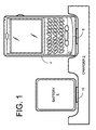
- FIG. 1 is simplified front view of a charger 2, a battery-operated device 4 and a battery 6, in accordance with some embodiments of the invention.
- Charger 2 may have, for example, two charging ports 8 and 10.
- Battery-operated device 4 is coupled to charging port 8 and battery 6 is coupled to charging port 10.
- Charger 2 may be capable of simultaneously charging the battery of battery-operated device 4 and battery 6.
- charger 2 may have more than two charging ports, and may therefore be capable of simultaneously charging more than two batteries.
- a charger according to some embodiments of the invention may have five charging ports, and may be capable of simultaneously charging one, two, three, four or five batteries.
- FIG. 2 is a simplified block diagram of charger 2, battery-operated device 4 and battery 6, in accordance with some embodiments of the invention.
- Battery-operated device 4 may include a battery 5 and charging circuitry 7.
- Charger 2 may have, for example, two charging ports 8 and 10, having respective positive terminals 12 and 14, and respective negative terminals 16 and 18.
- a positive terminal 20 of battery 5 may be coupled to positive terminal 12 of charging port 8 via charging circuitry 7 and a negative terminal 22 of battery 5 may be coupled to negative terminal 16 of charging port 8 via charging circuitry 7.
- a positive terminal 24 of battery 6 may be coupled to positive terminal 14 of charging port 10 and a negative terminal 26 of battery 6 may be coupled to negative terminal 18 of charging port 10.
- FIG. 3 is a simplified block diagram of charger 2 and batteries 5 and 6 to be charged, in accordance with some embodiments of the invention. Many of the elements in FIG. 3 are the same as or similar to elements of FIG. 2, and therefore the following description applies equally to FIG. 2 and FIG. 3.
- Charger 2 may include a current source 28, a current allocator 30, a controller 32 and a measurement unit 34.
- Current source 28 may be capable of providing a current 36 of, for example, 500 milliamps (mA).
- Current allocator 30 may receive current 36, and may be capable of allocating a current portion 40 of current 36 to charging port 8 and a current portion 42 of current 36 to charging port 10.
- current portion 40 may be 140 mA and current portion 42 may be 360 mA.
- the allocation proportions of current 36 to current portions 40 and 42 may be controllable, at least in part, by controller 32 via control signals 38.
- controller 32 may optionally receive battery type identifications 45 and 46 from batteries 5 and 6, respectively.
- charging circuitry 7 may obtain the battery type identification from battery 5 and pass the information onwards to controller 32.
- Controller 32 may comprise one or more look up tables 48 containing information regarding one or more types of batteries. Such information may include, for example, the maximum charge capacity, the average current drain from the battery during usage, and the estimated relationship between the output voltage of the battery and the unused capacity of the battery.
- the type of batteries 5 and 6, and optionally the average current drain from batteries 5 and 6 during usage may be known in advance.
- mechanical constraints may mean that only one type of battery can be coupled to charging port 8 or to charging port 10.
- Measurement unit 34 may be capable of measuring the voltage difference between positive terminal 12 and negative terminal 16, and may be capable of measuring the voltage difference between positive terminal 14 and negative terminal 18.
- Measurement unit 34 may be controlled, at least in part, by controller 32. Controller 32 may command measurement unit 34 via signals 52 to measure the voltage difference between positive terminal 12 and negative terminal 16, and may receive the measurement result from measurement unit 34 via signals 54. In addition, controller 32 may command measurement unit 34 via signals 52 to measure the voltage difference between positive terminal 14 and negative terminal 18, and may receive the measurement result from measurement unit 34 via signals 54.
- battery-operated device 4 may report the actual voltage of battery 5 to controller 32 via a data path 55.
- Controller 32 may use look-up table 48 to determine the charge in the battery coupled to the charging port from the measurement of the voltage difference and the average current drain from the battery during usage.
- FIG. 4 is a flowchart of an exemplary method for simultaneously charging multiple rechargeable batteries, according to some embodiments of the invention.
- the exemplary method of FIG. 4 may be executed by controller 32, although the invention is not limited in this respect.
- Controller 32 may check whether any batteries are coupled to charging ports 8 and 10 (100). If no battery is coupled to charging ports 8 and 10 (102), the method may continue to block 100. However, if at least one battery is coupled (to either charging port 8, charging port 10, or to both), controller 32 may determine the types of the coupled batteries (104). The difference between the maximum charge capacity and the charge in the battery is determined for each of the coupled batteries (106). For example, this difference is determined by measuring the battery's voltage and obtaining the corresponding information from look up tables 48 for the average current drain from the battery during usage.
- the charging current for each of the coupled batteries is set (e.g., current portions 40 and 42) so that all coupled batteries may become fully charged at substantially the same time (108).
- the method may repeat from block 100 in order to detect changes in the number and type of coupled batteries, and to adjust the charging currents accordingly, and to adjust the charging currents according to the progress of the charging process.
- Battery 5 Battery 6 maximum capacity 600 mAh 1000 mAh charge in battery 360 mAh 400 mAh amount of charge required to fully charge battery 240 mAh 600 mAh time required to fully charge battery 240 mAh / (current portion 40) 600 mAh / (current portion 42)
- the total available current (current 36) is 500 mA. Therefore, the sum of current portion 40 and current portion 42 may not exceed 500 mA.
- current allocator 30 will allocate current portion 40 to battery 5 and current portion 42 to battery 6 according to the following calculation:
- controller 32 may recheck the charge of the batteries from time to time so that current allocator 30 can readjust the charge allocation accordingly.
Abstract
Description
- The invention relates generally to chargers for rechargeable batteries of mobile electronic devices. In particular, embodiments of the invention relate to a method for simultaneously charging the battery inside a mobile electronic device and a second battery for the mobile electronic device.
- Many users of mobile electronic devices have a second battery on hand for use when the battery in the mobile electronic device is discharged. After discharging both batteries, a user will want to recharge the two batteries as quickly as possible.
- Current options include the following:
- a) Fully charging one battery using the charging circuitry in the mobile electronic device and an external power adapter, then exchanging the two batteries to charge the second battery.
- b) Charging one battery using the charging circuitry in the mobile electronic device and an external power adapter, and simultaneously charging the second battery in an external battery charger;
- c) Charging one battery using the charging circuitry in the mobile electronic device connected to a dual-output external battery charger, with the second battery connected to the other output of the external battery charger. The external battery charger charges the batteries in sequential order without user intervention, or trickle charges one of the batteries while charging the other battery at full rate until it is fully charged, or gives one battery priority and provides all available current to that battery and any remaining current that can be supplied to the charger is provided to the secondary battery.
-
- These options either extend the charge time by charging the batteries in sequential order, by keeping one battery in slow-rate trickle charge until it is fully charged, or require the user to carry two separate charging accessories with them.
- In some embodiments of the invention, charging currents from a single current source may be allocated to two or more separate charging ports having two or more rechargeable batteries coupled respectively thereto so that the two or more rechargeable batteries will be fully charged at substantially the same time. Relative amounts of charge required to fully charge the two or more rechargeable batteries may be determined. A charging current allocated to a particular charging port may be determined at least in part on an average current drain during usage of the rechargeable battery coupled to the particular charging port.
- In some embodiments of the invention, a charger has a single current source and two or more separate charging ports. The charger includes a current allocator to allocate charging currents from the single current source to the two or more charging ports. The charger also includes a controller to determine the charging currents so that two or more rechargeable batteries coupled respectively to the two or more charging ports will be fully charged at substantially the same time.
- The charger may include one or more lookup tables and a measurement unit to measure voltage differences at the two or more charging ports. The controller may determine from the one or more lookup tables an amount of charge required to fully charge a battery based on the measured voltage difference, a battery type, and an average current drain of the battery during usage.
- A particular one of the rechargeable batteries may be inside a battery-operated device. The controller may receive a voltage of the particular rechargeable battery from the battery-operated device. The charger may include one or more look up tables, and the controller may determine from the one or more lookup tables an amount of charge required to fully charge a battery based on the received voltage, a battery type, and an average current drain of the battery during usage.
- Embodiments of the invention are illustrated by way of example and not limitation in the figures of the accompanying drawings, in which like reference numerals indicate corresponding, analogous or similar elements, and in which:
- FIG. 1 is simplified front view of a charger, a battery-operated device and a battery, in accordance with some embodiments of the invention;
- FIG. 2 is a simplified block diagram of a charger, a battery-operated device and a battery, in accordance with some embodiments of the invention;
- FIG. 3 is a simplified block diagram of a charger and two batteries, in accordance with some embodiments of the invention; and
- FIG. 4 is a flowchart of an exemplary method for simultaneously charging multiple rechargeable batteries, according to some embodiments of the invention.
- It will be appreciated that for simplicity and clarity of illustration, elements shown in the figures have not necessarily been drawn to scale. For example, the dimensions of some of the elements may be exaggerated relative to other elements for clarity.
- In the following detailed description, numerous specific details are set forth in order to provide a thorough understanding of embodiments of the invention. However it will be understood by those of ordinary skill in the art that the embodiments of the invention may be practiced without these specific details. In other instances, well-known methods, procedures, components and circuits have not been described in detail so as not to obscure the invention.
- Reference is made to FIG. 1, which is simplified front view of a
charger 2, a battery-operateddevice 4 and abattery 6, in accordance with some embodiments of the invention.Charger 2 may have, for example, twocharging ports device 4 is coupled tocharging port 8 andbattery 6 is coupled tocharging port 10. -
Charger 2 may be capable of simultaneously charging the battery of battery-operateddevice 4 andbattery 6. In some embodiments of the invention,charger 2 may have more than two charging ports, and may therefore be capable of simultaneously charging more than two batteries. For example, a charger according to some embodiments of the invention may have five charging ports, and may be capable of simultaneously charging one, two, three, four or five batteries. - Reference is now made to FIG. 2, which is a simplified block diagram of
charger 2, battery-operateddevice 4 andbattery 6, in accordance with some embodiments of the invention. Battery-operateddevice 4 may include abattery 5 and charging circuitry 7.Charger 2 may have, for example, twocharging ports positive terminals 12 and 14, and respectivenegative terminals - For
charger 2 to chargebattery 5, apositive terminal 20 ofbattery 5 may be coupled topositive terminal 12 ofcharging port 8 via charging circuitry 7 and anegative terminal 22 ofbattery 5 may be coupled tonegative terminal 16 ofcharging port 8 via charging circuitry 7. Similarly, forcharger 2 to chargebattery 6, apositive terminal 24 ofbattery 6 may be coupled to positive terminal 14 ofcharging port 10 and anegative terminal 26 ofbattery 6 may be coupled tonegative terminal 18 ofcharging port 10. - Reference is made additionally to FIG. 3, which is a simplified block diagram of
charger 2 andbatteries -
Charger 2 may include acurrent source 28, acurrent allocator 30, acontroller 32 and ameasurement unit 34.Current source 28 may be capable of providing a current 36 of, for example, 500 milliamps (mA).Current allocator 30 may receive current 36, and may be capable of allocating acurrent portion 40 of current 36 to chargingport 8 and acurrent portion 42 of current 36 to chargingport 10. For example,current portion 40 may be 140 mA andcurrent portion 42 may be 360 mA. - The allocation proportions of current 36 to
current portions controller 32 viacontrol signals 38. - According to some embodiments of the invention,
controller 32 may optionally receivebattery type identifications batteries battery 5 coupled to the charging port via battery-operateddevice 4, as shown in FIG. 2, charging circuitry 7 may obtain the battery type identification frombattery 5 and pass the information onwards to controller 32.)Controller 32 may comprise one or more look up tables 48 containing information regarding one or more types of batteries. Such information may include, for example, the maximum charge capacity, the average current drain from the battery during usage, and the estimated relationship between the output voltage of the battery and the unused capacity of the battery. - According to other embodiments of the invention, the type of
batteries batteries port 8 or to chargingport 10. -
Measurement unit 34 may be capable of measuring the voltage difference betweenpositive terminal 12 andnegative terminal 16, and may be capable of measuring the voltage difference between positive terminal 14 andnegative terminal 18. -
Measurement unit 34 may be controlled, at least in part, bycontroller 32.Controller 32 maycommand measurement unit 34 viasignals 52 to measure the voltage difference betweenpositive terminal 12 andnegative terminal 16, and may receive the measurement result frommeasurement unit 34 viasignals 54. In addition,controller 32 maycommand measurement unit 34 viasignals 52 to measure the voltage difference between positive terminal 14 andnegative terminal 18, and may receive the measurement result frommeasurement unit 34 viasignals 54. - In some situations where
battery 5 is included in battery-operateddevice 4, and battery-operateddevice 4 is coupled tocharging port 8, the voltage difference betweenpositive terminal 12 andnegative terminal 16 may not represent the voltage ofbattery 5. In such situations, battery-operateddevice 4 may report the actual voltage ofbattery 5 tocontroller 32 via adata path 55. -
Controller 32 may use look-up table 48 to determine the charge in the battery coupled to the charging port from the measurement of the voltage difference and the average current drain from the battery during usage. - FIG. 4 is a flowchart of an exemplary method for simultaneously charging multiple rechargeable batteries, according to some embodiments of the invention. The exemplary method of FIG. 4 may be executed by
controller 32, although the invention is not limited in this respect. -
Controller 32 may check whether any batteries are coupled to chargingports 8 and 10 (100). If no battery is coupled to chargingports 8 and 10 (102), the method may continue to block 100. However, if at least one battery is coupled (to either chargingport 8, chargingport 10, or to both),controller 32 may determine the types of the coupled batteries (104). The difference between the maximum charge capacity and the charge in the battery is determined for each of the coupled batteries (106). For example, this difference is determined by measuring the battery's voltage and obtaining the corresponding information from look up tables 48 for the average current drain from the battery during usage. - The charging current for each of the coupled batteries is set (e.g.,
current portions 40 and 42) so that all coupled batteries may become fully charged at substantially the same time (108). - From time to time, the method may repeat from
block 100 in order to detect changes in the number and type of coupled batteries, and to adjust the charging currents accordingly, and to adjust the charging currents according to the progress of the charging process. - The following table lists an example where
battery 5 is charged to 60% of its maximum capacity andbattery 6 is charged to 40% of its maximum capacity.Battery 5Battery 6maximum capacity 600 mAh 1000 mAh charge in battery 360 mAh 400 mAh amount of charge required to fully charge battery 240 mAh 600 mAh time required to fully charge battery 240 mAh /
(current portion 40)600 mAh /
(current portion 42) - In the example given in FIG. 1, the total available current (current 36) is 500 mA. Therefore, the sum of
current portion 40 andcurrent portion 42 may not exceed 500 mA. - In order for both
battery 5 andbattery 6 to be fully charged at substantially the same time,current allocator 30 will allocatecurrent portion 40 tobattery 5 andcurrent portion 42 tobattery 6 according to the following calculation: - 240 mAh * (current portion 42) = 600 mAh * (current portion 40)
- 240 mAh * (500 - current portion 40) = 600 mAh * (current portion 40)
-
current portion 40 = 142 mA -
current portion 42 = 358 mA -
- Since the charge profile of rechargeable batteries is not linear in nature,
controller 32 may recheck the charge of the batteries from time to time so thatcurrent allocator 30 can readjust the charge allocation accordingly. - While certain features of the invention have been illustrated and described herein, many modifications, substitutions, changes, and equivalents will now occur to those of ordinary skill in the art. It is, therefore, to be understood that the appended claims are intended to cover all such modifications and changes as fall within the spirit of the invention.
Claims (6)
- A method comprising:allocating charging currents from a single current source (28) to two or more separate charging ports (8, 10) having two or more rechargeable batteries (5, 6) coupled respectively thereto so that said two or more rechargeable batteries (5, 6) will be fully charged at substantially the same time.
- The method of claim 1, further comprising:determining relative amounts of charge required to fully charge said two or more rechargeable batteries (5, 6).
- The method of claim 1 or claim 2, further comprising:determining a charging current allocated to a particular charging port at least in part on an average current drain during usage of the rechargeable battery coupled to said particular charging port.
- A charger (2) comprising:a single current source (28);two or more separate charging ports (8, 10);a current allocator (30) to allocate charging currents from said single current source (28) to said two or more ports (8, 10); anda controller (32) to determine said charging currents so that two or more rechargeable batteries (5, 6) coupled respectively to said two or more ports (8, 10) will be fully charged at substantially the same time.
- The charger (2) of claim 4, further comprising:wherein said controller (32) is to determine from said one or more lookup tables (48) an amount of charge required to fully charge a battery based on said measured voltage difference, a battery type, and an average current drain of said battery during usage.a measurement unit (34) to measure voltage differences at said two or more ports (8, 10); andone or more lookup tables (48),
- The charger (2) of claim 4, wherein a particular one of said rechargeable batteries (5) is inside a battery-operated device (4) and said controller (32) is to receive a voltage of said particular rechargeable battery (5) from said battery-operated device (4), the charger (2) further comprising:wherein said controller (32) is to determine from said one or more lookup tables (48) an amount of charge required to fully charge said particular battery (5) based on said received voltage, a battery type, and an average current drain of said particular battery during usage.one or more lookup tables (48),
Priority Applications (5)
| Application Number | Priority Date | Filing Date | Title |
|---|---|---|---|
| AT04251147T ATE508513T1 (en) | 2004-02-27 | 2004-02-27 | DEVICE AND METHOD FOR SIMULTANEOUS CHARGING OF SEVERAL BATTERIES |
| DE602004032511T DE602004032511D1 (en) | 2004-02-27 | 2004-02-27 | Apparatus and method for simultaneous charging of multiple accumulators |
| EP04251147A EP1569316B1 (en) | 2004-02-27 | 2004-02-27 | Method and apparatus for simultaneously charging multiple rechargeable batteries |
| CA002498113A CA2498113C (en) | 2004-02-27 | 2005-02-23 | Methods and apparatus for simultaneously charging multiple rechargeable batteries |
| HK06102383.5A HK1081332A1 (en) | 2004-02-27 | 2006-02-23 | Method and apparatus for simultaneously charging multiple rechargeable batteries |
Applications Claiming Priority (1)
| Application Number | Priority Date | Filing Date | Title |
|---|---|---|---|
| EP04251147A EP1569316B1 (en) | 2004-02-27 | 2004-02-27 | Method and apparatus for simultaneously charging multiple rechargeable batteries |
Publications (2)
| Publication Number | Publication Date |
|---|---|
| EP1569316A1 true EP1569316A1 (en) | 2005-08-31 |
| EP1569316B1 EP1569316B1 (en) | 2011-05-04 |
Family
ID=34746116
Family Applications (1)
| Application Number | Title | Priority Date | Filing Date |
|---|---|---|---|
| EP04251147A Expired - Lifetime EP1569316B1 (en) | 2004-02-27 | 2004-02-27 | Method and apparatus for simultaneously charging multiple rechargeable batteries |
Country Status (5)
| Country | Link |
|---|---|
| EP (1) | EP1569316B1 (en) |
| AT (1) | ATE508513T1 (en) |
| CA (1) | CA2498113C (en) |
| DE (1) | DE602004032511D1 (en) |
| HK (1) | HK1081332A1 (en) |
Cited By (2)
| Publication number | Priority date | Publication date | Assignee | Title |
|---|---|---|---|---|
| CN116470596A (en) * | 2022-01-11 | 2023-07-21 | 荣耀终端有限公司 | Power adapter, charging system and charging method |
| WO2024007687A1 (en) * | 2022-07-06 | 2024-01-11 | 荣耀终端有限公司 | Multi-battery power supply, charging/discharging method, and electronic device |
Citations (3)
| Publication number | Priority date | Publication date | Assignee | Title |
|---|---|---|---|---|
| US5717309A (en) * | 1995-10-30 | 1998-02-10 | Samsung Electronics Co. | Dual battery charging device |
| US6002237A (en) * | 1997-03-14 | 1999-12-14 | International Components Corp. | Microcontrolled battery charger |
| EP1124300A2 (en) * | 2000-02-08 | 2001-08-16 | Sony Corporation | Battery charging apparatus, battery pack and method for charging secondary battery |
Family Cites Families (2)
| Publication number | Priority date | Publication date | Assignee | Title |
|---|---|---|---|---|
| DE20004691U1 (en) * | 2000-03-14 | 2000-06-29 | Yang Wen Chin | Charging device with USB interface for a GSM telephone battery |
| FR2841699B1 (en) * | 2002-07-01 | 2005-10-14 | France Telecom | CHARGER AND CHARGING DEVICE |
-
2004
- 2004-02-27 EP EP04251147A patent/EP1569316B1/en not_active Expired - Lifetime
- 2004-02-27 AT AT04251147T patent/ATE508513T1/en not_active IP Right Cessation
- 2004-02-27 DE DE602004032511T patent/DE602004032511D1/en not_active Expired - Lifetime
-
2005
- 2005-02-23 CA CA002498113A patent/CA2498113C/en active Active
-
2006
- 2006-02-23 HK HK06102383.5A patent/HK1081332A1/en not_active IP Right Cessation
Patent Citations (3)
| Publication number | Priority date | Publication date | Assignee | Title |
|---|---|---|---|---|
| US5717309A (en) * | 1995-10-30 | 1998-02-10 | Samsung Electronics Co. | Dual battery charging device |
| US6002237A (en) * | 1997-03-14 | 1999-12-14 | International Components Corp. | Microcontrolled battery charger |
| EP1124300A2 (en) * | 2000-02-08 | 2001-08-16 | Sony Corporation | Battery charging apparatus, battery pack and method for charging secondary battery |
Cited By (3)
| Publication number | Priority date | Publication date | Assignee | Title |
|---|---|---|---|---|
| CN116470596A (en) * | 2022-01-11 | 2023-07-21 | 荣耀终端有限公司 | Power adapter, charging system and charging method |
| CN116470596B (en) * | 2022-01-11 | 2024-04-05 | 荣耀终端有限公司 | Power adapter, charging system and charging method |
| WO2024007687A1 (en) * | 2022-07-06 | 2024-01-11 | 荣耀终端有限公司 | Multi-battery power supply, charging/discharging method, and electronic device |
Also Published As
| Publication number | Publication date |
|---|---|
| HK1081332A1 (en) | 2006-05-12 |
| DE602004032511D1 (en) | 2011-06-16 |
| EP1569316B1 (en) | 2011-05-04 |
| CA2498113C (en) | 2009-04-28 |
| CA2498113A1 (en) | 2005-08-27 |
| ATE508513T1 (en) | 2011-05-15 |
Similar Documents
| Publication | Publication Date | Title |
|---|---|---|
| US7116079B2 (en) | Methods and apparatus for simultaneously charging multiple rechargable batteries | |
| US8384390B2 (en) | Systems and methods for determining battery capacity level | |
| KR102475482B1 (en) | Method and apparatus of controlling battery, and battery pack enabling the method | |
| US8436575B2 (en) | Battery ID setting system and method of driving the same | |
| US8022662B2 (en) | Power supply for battery powered devices | |
| KR101502230B1 (en) | Charging method of battery and battery charging system | |
| EP3078073B1 (en) | Device and method for controlling a plurality of cells of a battery | |
| US10873201B2 (en) | Battery management apparatus and method for protecting a lithium iron phosphate cell from over-voltage using the same | |
| US20120098500A1 (en) | Method of detecting charger type and estimating remaining recharging time for mobile devices with usb recharging | |
| CN101322280A (en) | Battery pack, electronic device and method for detecting remaining quantity in battery | |
| CN101636872A (en) | Quick charging method of lithium based secondary battery and electronic apparatus employing it | |
| US11901517B2 (en) | Method and system for assessing a state of charge/discharge (SOC/SOD) for an electrochemical cell | |
| EP1994625A2 (en) | Battery charger | |
| EP3200310A1 (en) | Electrical storage system, control apparatus, and control method | |
| KR20160024589A (en) | Battery charging method and battery pack using the method | |
| KR102045047B1 (en) | Maximum capacity charging apparatus considering SOH unbalance of battery module and control method thereof | |
| US20180123369A1 (en) | Temperature dependent charge algorithm | |
| KR101614046B1 (en) | Apparatus for managing battery system | |
| CN103444045A (en) | Information processing device | |
| JP4749290B2 (en) | Power supply device and voltage management IC used therefor | |
| CA2498113C (en) | Methods and apparatus for simultaneously charging multiple rechargeable batteries | |
| JP5165405B2 (en) | Charge control circuit, battery pack, and charging system | |
| CN101278458A (en) | System and method for monitoring power supplied to a battery | |
| JP2007250364A (en) | Internal charging device and charging method of secondary battery | |
| TW201743533A (en) | Balanced battery charging system |
Legal Events
| Date | Code | Title | Description |
|---|---|---|---|
| PUAI | Public reference made under article 153(3) epc to a published international application that has entered the european phase |
Free format text: ORIGINAL CODE: 0009012 |
|
| 17P | Request for examination filed |
Effective date: 20040326 |
|
| AK | Designated contracting states |
Kind code of ref document: A1 Designated state(s): AT BE BG CH CY CZ DE DK EE ES FI FR GB GR HU IE IT LI LU MC NL PT RO SE SI SK TR |
|
| AX | Request for extension of the european patent |
Extension state: AL LT LV MK |
|
| REG | Reference to a national code |
Ref country code: HK Ref legal event code: DE Ref document number: 1081332 Country of ref document: HK |
|
| AKX | Designation fees paid |
Designated state(s): AT BE BG CH CY CZ DE DK EE ES FI FR GB GR HU IE IT LI LU MC NL PT RO SE SI SK TR |
|
| AXX | Extension fees paid |
Extension state: MK Payment date: 20040326 Extension state: AL Payment date: 20040326 Extension state: LV Payment date: 20040326 Extension state: LT Payment date: 20040326 |
|
| GRAP | Despatch of communication of intention to grant a patent |
Free format text: ORIGINAL CODE: EPIDOSNIGR1 |
|
| GRAS | Grant fee paid |
Free format text: ORIGINAL CODE: EPIDOSNIGR3 |
|
| GRAA | (expected) grant |
Free format text: ORIGINAL CODE: 0009210 |
|
| AK | Designated contracting states |
Kind code of ref document: B1 Designated state(s): AT BE BG CH CY CZ DE DK EE ES FI FR GB GR HU IE IT LI LU MC NL PT RO SE SI SK TR |
|
| AX | Request for extension of the european patent |
Extension state: AL LT LV MK |
|
| REG | Reference to a national code |
Ref country code: GB Ref legal event code: FG4D |
|
| REG | Reference to a national code |
Ref country code: CH Ref legal event code: EP |
|
| REG | Reference to a national code |
Ref country code: IE Ref legal event code: FG4D |
|
| REF | Corresponds to: |
Ref document number: 602004032511 Country of ref document: DE Date of ref document: 20110616 Kind code of ref document: P |
|
| REG | Reference to a national code |
Ref country code: DE Ref legal event code: R096 Ref document number: 602004032511 Country of ref document: DE Effective date: 20110616 |
|
| REG | Reference to a national code |
Ref country code: HK Ref legal event code: GR Ref document number: 1081332 Country of ref document: HK |
|
| REG | Reference to a national code |
Ref country code: NL Ref legal event code: VDEP Effective date: 20110504 |
|
| LTIE | Lt: invalidation of european patent or patent extension |
Effective date: 20110504 |
|
| PG25 | Lapsed in a contracting state [announced via postgrant information from national office to epo] |
Ref country code: SE Free format text: LAPSE BECAUSE OF FAILURE TO SUBMIT A TRANSLATION OF THE DESCRIPTION OR TO PAY THE FEE WITHIN THE PRESCRIBED TIME-LIMIT Effective date: 20110504 Ref country code: PT Free format text: LAPSE BECAUSE OF FAILURE TO SUBMIT A TRANSLATION OF THE DESCRIPTION OR TO PAY THE FEE WITHIN THE PRESCRIBED TIME-LIMIT Effective date: 20110905 |
|
| PG25 | Lapsed in a contracting state [announced via postgrant information from national office to epo] |
Ref country code: AT Free format text: LAPSE BECAUSE OF FAILURE TO SUBMIT A TRANSLATION OF THE DESCRIPTION OR TO PAY THE FEE WITHIN THE PRESCRIBED TIME-LIMIT Effective date: 20110504 Ref country code: GR Free format text: LAPSE BECAUSE OF FAILURE TO SUBMIT A TRANSLATION OF THE DESCRIPTION OR TO PAY THE FEE WITHIN THE PRESCRIBED TIME-LIMIT Effective date: 20110805 Ref country code: ES Free format text: LAPSE BECAUSE OF FAILURE TO SUBMIT A TRANSLATION OF THE DESCRIPTION OR TO PAY THE FEE WITHIN THE PRESCRIBED TIME-LIMIT Effective date: 20110815 Ref country code: CY Free format text: LAPSE BECAUSE OF FAILURE TO SUBMIT A TRANSLATION OF THE DESCRIPTION OR TO PAY THE FEE WITHIN THE PRESCRIBED TIME-LIMIT Effective date: 20110504 Ref country code: BE Free format text: LAPSE BECAUSE OF FAILURE TO SUBMIT A TRANSLATION OF THE DESCRIPTION OR TO PAY THE FEE WITHIN THE PRESCRIBED TIME-LIMIT Effective date: 20110504 Ref country code: SI Free format text: LAPSE BECAUSE OF FAILURE TO SUBMIT A TRANSLATION OF THE DESCRIPTION OR TO PAY THE FEE WITHIN THE PRESCRIBED TIME-LIMIT Effective date: 20110504 Ref country code: FI Free format text: LAPSE BECAUSE OF FAILURE TO SUBMIT A TRANSLATION OF THE DESCRIPTION OR TO PAY THE FEE WITHIN THE PRESCRIBED TIME-LIMIT Effective date: 20110504 |
|
| PG25 | Lapsed in a contracting state [announced via postgrant information from national office to epo] |
Ref country code: NL Free format text: LAPSE BECAUSE OF FAILURE TO SUBMIT A TRANSLATION OF THE DESCRIPTION OR TO PAY THE FEE WITHIN THE PRESCRIBED TIME-LIMIT Effective date: 20110504 |
|
| PG25 | Lapsed in a contracting state [announced via postgrant information from national office to epo] |
Ref country code: CZ Free format text: LAPSE BECAUSE OF FAILURE TO SUBMIT A TRANSLATION OF THE DESCRIPTION OR TO PAY THE FEE WITHIN THE PRESCRIBED TIME-LIMIT Effective date: 20110504 Ref country code: EE Free format text: LAPSE BECAUSE OF FAILURE TO SUBMIT A TRANSLATION OF THE DESCRIPTION OR TO PAY THE FEE WITHIN THE PRESCRIBED TIME-LIMIT Effective date: 20110504 |
|
| PG25 | Lapsed in a contracting state [announced via postgrant information from national office to epo] |
Ref country code: DK Free format text: LAPSE BECAUSE OF FAILURE TO SUBMIT A TRANSLATION OF THE DESCRIPTION OR TO PAY THE FEE WITHIN THE PRESCRIBED TIME-LIMIT Effective date: 20110504 Ref country code: RO Free format text: LAPSE BECAUSE OF FAILURE TO SUBMIT A TRANSLATION OF THE DESCRIPTION OR TO PAY THE FEE WITHIN THE PRESCRIBED TIME-LIMIT Effective date: 20110504 Ref country code: SK Free format text: LAPSE BECAUSE OF FAILURE TO SUBMIT A TRANSLATION OF THE DESCRIPTION OR TO PAY THE FEE WITHIN THE PRESCRIBED TIME-LIMIT Effective date: 20110504 |
|
| PLBE | No opposition filed within time limit |
Free format text: ORIGINAL CODE: 0009261 |
|
| STAA | Information on the status of an ep patent application or granted ep patent |
Free format text: STATUS: NO OPPOSITION FILED WITHIN TIME LIMIT |
|
| 26N | No opposition filed |
Effective date: 20120207 |
|
| PG25 | Lapsed in a contracting state [announced via postgrant information from national office to epo] |
Ref country code: IT Free format text: LAPSE BECAUSE OF FAILURE TO SUBMIT A TRANSLATION OF THE DESCRIPTION OR TO PAY THE FEE WITHIN THE PRESCRIBED TIME-LIMIT Effective date: 20110504 |
|
| REG | Reference to a national code |
Ref country code: DE Ref legal event code: R097 Ref document number: 602004032511 Country of ref document: DE Effective date: 20120207 |
|
| PG25 | Lapsed in a contracting state [announced via postgrant information from national office to epo] |
Ref country code: MC Free format text: LAPSE BECAUSE OF NON-PAYMENT OF DUE FEES Effective date: 20120229 |
|
| REG | Reference to a national code |
Ref country code: CH Ref legal event code: PL |
|
| PG25 | Lapsed in a contracting state [announced via postgrant information from national office to epo] |
Ref country code: LI Free format text: LAPSE BECAUSE OF NON-PAYMENT OF DUE FEES Effective date: 20120229 Ref country code: CH Free format text: LAPSE BECAUSE OF NON-PAYMENT OF DUE FEES Effective date: 20120229 |
|
| REG | Reference to a national code |
Ref country code: IE Ref legal event code: MM4A |
|
| PG25 | Lapsed in a contracting state [announced via postgrant information from national office to epo] |
Ref country code: IE Free format text: LAPSE BECAUSE OF NON-PAYMENT OF DUE FEES Effective date: 20120227 |
|
| PG25 | Lapsed in a contracting state [announced via postgrant information from national office to epo] |
Ref country code: BG Free format text: LAPSE BECAUSE OF FAILURE TO SUBMIT A TRANSLATION OF THE DESCRIPTION OR TO PAY THE FEE WITHIN THE PRESCRIBED TIME-LIMIT Effective date: 20110804 |
|
| PG25 | Lapsed in a contracting state [announced via postgrant information from national office to epo] |
Ref country code: TR Free format text: LAPSE BECAUSE OF FAILURE TO SUBMIT A TRANSLATION OF THE DESCRIPTION OR TO PAY THE FEE WITHIN THE PRESCRIBED TIME-LIMIT Effective date: 20110504 |
|
| PG25 | Lapsed in a contracting state [announced via postgrant information from national office to epo] |
Ref country code: LU Free format text: LAPSE BECAUSE OF NON-PAYMENT OF DUE FEES Effective date: 20120227 |
|
| PG25 | Lapsed in a contracting state [announced via postgrant information from national office to epo] |
Ref country code: HU Free format text: LAPSE BECAUSE OF FAILURE TO SUBMIT A TRANSLATION OF THE DESCRIPTION OR TO PAY THE FEE WITHIN THE PRESCRIBED TIME-LIMIT Effective date: 20040227 |
|
| REG | Reference to a national code |
Ref country code: DE Ref legal event code: R082 Ref document number: 602004032511 Country of ref document: DE Representative=s name: MERH-IP MATIAS ERNY REICHL HOFFMANN, DE |
|
| REG | Reference to a national code |
Ref country code: DE Ref legal event code: R082 Ref document number: 602004032511 Country of ref document: DE Representative=s name: MERH-IP MATIAS ERNY REICHL HOFFMANN, DE Effective date: 20140925 Ref country code: DE Ref legal event code: R081 Ref document number: 602004032511 Country of ref document: DE Owner name: BLACKBERRY LIMITED, WATERLOO, CA Free format text: FORMER OWNER: RESEARCH IN MOTION LTD., WATERLOO, ONTARIO, CA Effective date: 20140925 Ref country code: DE Ref legal event code: R082 Ref document number: 602004032511 Country of ref document: DE Representative=s name: MERH-IP MATIAS ERNY REICHL HOFFMANN PATENTANWA, DE Effective date: 20140925 |
|
| REG | Reference to a national code |
Ref country code: FR Ref legal event code: PLFP Year of fee payment: 13 |
|
| REG | Reference to a national code |
Ref country code: FR Ref legal event code: PLFP Year of fee payment: 14 |
|
| REG | Reference to a national code |
Ref country code: FR Ref legal event code: PLFP Year of fee payment: 15 |
|
| PGFP | Annual fee paid to national office [announced via postgrant information from national office to epo] |
Ref country code: FR Payment date: 20230223 Year of fee payment: 20 |
|
| PGFP | Annual fee paid to national office [announced via postgrant information from national office to epo] |
Ref country code: GB Payment date: 20230227 Year of fee payment: 20 Ref country code: DE Payment date: 20230223 Year of fee payment: 20 |
|
| REG | Reference to a national code |
Ref country code: DE Ref legal event code: R071 Ref document number: 602004032511 Country of ref document: DE |
|
| REG | Reference to a national code |
Ref country code: GB Ref legal event code: PE20 Expiry date: 20240226 |