EP1569297A1 - Antenne à très large bande V-UHF - Google Patents
Antenne à très large bande V-UHF Download PDFInfo
- Publication number
- EP1569297A1 EP1569297A1 EP05101169A EP05101169A EP1569297A1 EP 1569297 A1 EP1569297 A1 EP 1569297A1 EP 05101169 A EP05101169 A EP 05101169A EP 05101169 A EP05101169 A EP 05101169A EP 1569297 A1 EP1569297 A1 EP 1569297A1
- Authority
- EP
- European Patent Office
- Prior art keywords
- frequency
- band
- radiating
- antenna system
- fmsup
- Prior art date
- Legal status (The legal status is an assumption and is not a legal conclusion. Google has not performed a legal analysis and makes no representation as to the accuracy of the status listed.)
- Granted
Links
Images


Classifications
-
- H—ELECTRICITY
- H01—ELECTRIC ELEMENTS
- H01Q—ANTENNAS, i.e. RADIO AERIALS
- H01Q9/00—Electrically-short antennas having dimensions not more than twice the operating wavelength and consisting of conductive active radiating elements
- H01Q9/04—Resonant antennas
- H01Q9/16—Resonant antennas with feed intermediate between the extremities of the antenna, e.g. centre-fed dipole
- H01Q9/20—Two collinear substantially straight active elements; Substantially straight single active elements
- H01Q9/22—Rigid rod or equivalent tubular element or elements
-
- H—ELECTRICITY
- H01—ELECTRIC ELEMENTS
- H01Q—ANTENNAS, i.e. RADIO AERIALS
- H01Q21/00—Antenna arrays or systems
- H01Q21/06—Arrays of individually energised antenna units similarly polarised and spaced apart
- H01Q21/08—Arrays of individually energised antenna units similarly polarised and spaced apart the units being spaced along or adjacent to a rectilinear path
- H01Q21/10—Collinear arrangements of substantially straight elongated conductive units
-
- H—ELECTRICITY
- H01—ELECTRIC ELEMENTS
- H01Q—ANTENNAS, i.e. RADIO AERIALS
- H01Q21/00—Antenna arrays or systems
- H01Q21/30—Combinations of separate antenna units operating in different wavebands and connected to a common feeder system
-
- H—ELECTRICITY
- H01—ELECTRIC ELEMENTS
- H01Q—ANTENNAS, i.e. RADIO AERIALS
- H01Q5/00—Arrangements for simultaneous operation of antennas on two or more different wavebands, e.g. dual-band or multi-band arrangements
-
- H—ELECTRICITY
- H01—ELECTRIC ELEMENTS
- H01Q—ANTENNAS, i.e. RADIO AERIALS
- H01Q5/00—Arrangements for simultaneous operation of antennas on two or more different wavebands, e.g. dual-band or multi-band arrangements
- H01Q5/40—Imbricated or interleaved structures; Combined or electromagnetically coupled arrangements, e.g. comprising two or more non-connected fed radiating elements
Definitions
- the invention relates to an antennary system with a very wide band operating in transmission as in reception without adaptation. She is intended for example for the frequency band varying from 30 to 512 MHz, Very High Frequency VHF (Very High Frequencies) up to Ultra High Frequencies (UHF).
- VHF Very High Frequency
- UHF Ultra High Frequencies
- This band includes in particular the classical bands: the usual VHF-FM band, or VHF frequency modulation from 30 to 88 MHz (or in English VHF - Frequency Modulation), the VHF-AM or VHF band amplitude modulation from 100 to 160 MHz (in English VHF - Amplitude Modulation) and the UHF-AM band from 225 to 400 MHz (UHF - Amplitude Modulation).
- Modern Transceiver (E / R) stations are likely operate in all frequency bands ranging from 30 to 512 MHz.
- the existing antennal systems associated with them especially those intended to be installed on mobiles, do not ensure a optimal functioning only by sub-frequency bands, for example, the VHF-FM band (30-88 MHz) or the VHF-AM band (100-160 MHz) or the UHF-AM band (225-400 MHz).
- the exploitation of these transmitters / receivers requires the use of several antennas and a switching device for selecting the most suitable antenna.
- radio frequencies such as radiocommunication antennas on board aircraft, aircraft antennal listening and jamming systems in electronic warfare, etc.
- these antennas have drawbacks that make them unsuitable for use on a land mobile. Indeed, they present either an efficiency that is too low for the requested radio range for the ground-ground links, the case of antennas on board aircraft, clutter incompatible with the dimensions of the vehicle.
- the idea of the present invention is to propose an antenna unique, capable of functioning without discontinuity at least throughout the frequency band of 30 to 512 MHz, ie in more than one decade, and having dimensions so that it can be installed in place a conventional VHF-FM radiocommunication antenna, ie having the shape of a whip while having a sufficient yield to guarantee radio frequency ranges at least equivalent to those of the existing equipment.
- a representation of such an antenna is schematically in Figure 1.
- the whip has a height for example of the order of 10 foot.
- the invention relates to a broadband antennal system which can radiate or receive radio frequency signals in a band of given frequency, comprising at least two radiating elements substantially collinear. It is characterized in that each element radiates in a frequency band, a first radiating element operating in the frequency band [Fhinf, Fhsup], a second radiating element operating in the band [Fminf, Fmsup], and in that at the hinge frequencies these two elements participate in the radiation.
- the frequency Fmsup is greater than or equal to frequency Fhinf.
- the antenna may comprise a third radiating element operating in the frequency band [Fbinf, Fbsup].
- the frequency Fbsup is for example greater than or equal to frequency Fminf, and the frequency Fmsup is for example greater than or equal to at the frequency Fhinf.
- FIG. 1 represents an example of antenna A installed on a V.
- This antenna consists for example of an element radiating 1 which is in the form of a whip, a base 2 which makes it possible to fix the antenna on the carrier vehicle and which usually comprises a power supply network allowing maximum power transfer from the transmitter / receiver to the radiator 1.
- a flexible element 3 is interspersed at its base. This flexible element known to those skilled in the art will not be detailed for reasons of simplification.
- the first dipole 11 placed at the top of the radiating assembly 1 is designed to work in the upper part [Fhinf to Fhsup] of the band useful, for this example from 200 to 512 MHz.
- the adaptation circuit and the band widening devices passers known to those skilled in the art to grant this dipole in the 200 to 512 MHz band are not detailed.
- the monopoly 13 located in the lower part of the antenna ensures operation in the low band Fbsup Fbinf from 30 to 100 MHz.
- the choice of a monopole type structure can be replaced by a dipolar structure.
- Monopoly allows in particular to obtain a more limited antenna size.
- This arrangement thus allows the radiating assembly 1 to operate from the lowest frequency Fbinf (in the given example 30 MHz) up to the highest frequency Fhsup (in this example 512 MHz) without around the hinge frequencies (Fhinf, Fmsup) and (Fminf, Fbsup) the radiation is disturbed thus prohibiting the use of these frequencies as in known antennas of the prior art.
- FIG. 3a shows an exemplary embodiment of an antenna according to the invention and Figure 3b a corresponding sectional view.
- openings are arranged 3a in certain elements making up the antenna.
- the dipoles are skirted dipoles, the references 11, 12, 13 of Figure 2 have been retained for reasons of simplification.
- the antenna comprises a first skirt dipole 11 located in its upper part, a second skirt 12 dipole collinear or substantially collinear to the first and a monopole 13 placed at the bottom of the antenna.
- the skirt dipole 11 consists of a first radiating element 11a, which can be made from a tubular section and a second radiating element 11b which is made from a hollow tubular element of length substantially identical to the length of the element 11a and in which is fed the power cable 21 of the antenna.
- These two elements radiators are fed at point 11c by connecting the upper end of the core 21a (FIG. 3b) of the coaxial feed cable 21 at the base of the element 11a and connecting the shield 21b (Fig.3b) of this cable 21 to around the top end 11bs of the element 11b to form what is usually referred to as a skirt.
- a quadrupole impedance matching can be inserted at point 11c.
- the length theoretical of quarter wave in meter is given by the known relation 300 / 4F (Mhz) is 0.375 meters in this example, where F is the frequency expressed in MHz.
- the colinear skirt dipole 12 is for example composed of a against skirt or skirt 12a and a skirt 12b, which constitute their own two, the two radiating elements of the dipole.
- a 12d skirt having the role of an insulation device usually designated by the word "stub" is interposed between these two elements.
- the perimeter of the upper end 12ds of the skirt 12d is connected to the shield 21b, while its other end 12di is connected to the lower part of the against skirt 12a.
- the supply of this dipole is carried out at level 12c in connecting the upper end of the core 22a of the coaxial cable supply 22 at the lower edge of the isolation device or "stub" 12d at point 12e and connecting the shield 22b of this cable 22 and the shield 21b cable 21 at the periphery of the upper end 12bs of the skirt 12b.
- stub isolation device
- this monopole 13 of the plan of mass M above which the antenna is installed cables 21 and 22 are wound around a core of known magnetic material 24, such as ferrite, iron powder, etc.
- a core of known magnetic material 24 such as ferrite, iron powder, etc.
- the supply of this monopole is realized by connecting the upper end of the core 23a of the cable 23 to one of the winding turns 25 at point 26 determined to obtain the best impedance matching in the frequency band [Fbinf to Fbsup].
- isolation devices acting as shocks such as devices based on ferrite beads, cores or ferrite tubes are interposed between these elements.
- the shields 21b, 22b, 23b and the mass of the supply network 14, are connected thereto by the connection assembly 30.
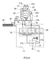
- the lower ends of the cable cores coaxial elements 21, 22 and 23 are respectively connected to the outputs 16, 17 and 18 of the power supply network 14, an exemplary embodiment of which is detailed in Figure 4.
- the radio frequency signal from the input 15 is divided in two by a hybrid 27 to the two lanes 27a and 27b.
- the first channel 27a is filtered by a bandpass filter [Fminf - Fmsup] 28, for the exemplary embodiment [100MHz - 200MHz] and constitutes after filtering the output 17.
- the other channel 27b is separated by a duplexer 29 in two subbands, one low [Fbinf - Fbsup], or [30MHz - 100MHz] for the exemplary embodiment and the other high [Fhinf - Fhsup], either [200MHz - 512MHz].
- the lower subband is connected to the output 18 and the High subband is connected to output 16.
- FIGS. 1 to 4 also applies to an antenna Broadband capable of radiating or receiving radio frequency a frequency band [Fminf, Fhsup], comprising two elements substantially collinear radiators (11, 12).
- the radiating element (11) operates in the frequency band [Fhinf, Fhsup]
- the radiating element (12) works in the band [Fminf, Fmsup], and at hinge frequencies between these two elements they both participate in radiation.
- the frequency Fmsup is greater than or equal to the frequency Fhinf.
Landscapes
- Physics & Mathematics (AREA)
- Electromagnetism (AREA)
- Variable-Direction Aerials And Aerial Arrays (AREA)
- Details Of Aerials (AREA)
Abstract
Description
- Elle présente un gain supérieur aux systèmes antennaires connus, de même encombrement et couvrant la même bande de fréquences.
- Elle permet de disposer d'une antenne unique, à très large bande, couvrant sans discontinuité plus d'une décade, en particulier de 30 à 512 MHz, et ceci avec un rendement et un gain supérieur aux antennes connues ayant la même bande de fréquences de fonctionnement.
- La figure 1 le schéma d'une antenne selon l'invention,
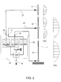
- La figure 2 le schéma synoptique et le principe de fonctionnement d'une telle antenne,
- Les figures 3a et 3b un exemple détaillé de réalisation d'antenne,
- La figure 4 un détail de réalisation du dispositif d'alimentation et de sa liaison avec l'antenne.
- Un ensemble rayonnant 1 constitué de deux dipôles colinéaires 11 et 12 et d'un monopôle 13,
- Un réseau d'alimentation 14 ayant une entrée 15 et trois sorties 16, 17, 18 qui sont connectées respectivement aux dipôles 11, 12 et au monopôle 13 par trois lignes de transmission respectivement 21, 22, 23.
- les signaux Sbh de la bande haute [Fhinf à Fhsup] provenant de l'entrée 15 vers la sortie 16 qui alimente l'élément rayonnant 11,
- les signaux Sbm de la bande moyenne [Fminf à Fmsup] provenant de l'entrée 15 vers la sortie 17 qui alimente l'élément rayonnant 12,
- les signaux Sbb de la bande basse [Fbinf à Fbsup] provenant de l'entrée 15 vers la sortie 18 qui alimente l'élément rayonnant 13.
- A la fréquence de recouvrement Fhinf, choisie égale ou sensiblement égale à Fmsup (pour l'exemple, fréquence de 200 MHz) entre la bande haute et la bande moyenne, le dipôle 11 présente un rayonnement de type demi onde alors que le dipôle 12 présente un rayonnement de type onde entière et en phase avec celui du dipôle 11. Cette mise en phase est obtenue par exemple dans l'exemple donné, en appariant radioélectriquement les longueurs des lignes de transmissions 21 et 22. La répartition de courant sur ces éléments rayonnants est représentée au schéma de la figure 2a.
- A la fréquence de recouvrement Fminf choisie égale ou sensiblement égale à Fbsup (pour l'exemple, fréquence de 100 MHz) entre la bande moyenne et la bande basse, le dipôle 12 présente un rayonnement de type demi-onde alors que le monopôle 13 présente un rayonnement de type onde entière et en phase avec celui du dipôle 12. Cette mise en phase est obtenue dans l'exemple donné en appairant radioélectriquement les longueurs des lignes de transmission 22 et 23. La répartition de courant sur ces éléments rayonnants est représentée au schéma de la figure 2b.
Claims (11)
- Système antennaire large bande pouvant rayonner ou recevoir des signaux radio-fréquence dans une bande de fréquences donnée, comprenant au moins deux éléments rayonnants sensiblement colinéaires (11, 12) caractérisé en ce que chaque élément rayonne dans une bande de fréquences, l'élément rayonnant (11) fonctionnant dans la bande de fréquences [Fhinf, Fhsup], l'élément rayonnant (12) fonctionnant dans la bande [Fminf, Fmsup], et en ce que aux fréquences charnières entre deux éléments adjacents, ces deux éléments participent au rayonnement.
- Système antennaire selon la revendication 1 caractérisé en ce que la fréquence Fmsup est supérieure ou égale à la fréquence Fhinf.
- Système antennaire selon la revendication 1 caractérisé en ce qu'il comporte un troisième élément rayonnant (13) fonctionnant dans la bande de fréquences [Fbinf, Fbsup].
- Système antennaire selon la revendication 3 caractérisé en ce que la fréquence Fbsup est supérieure ou égale à la fréquence Fminf, et la fréquence Fmsup est supérieure ou égale à la fréquence Fhinf.
- Système antennaire selon la revendication 3 caractérisé en ce que les éléments rayonnants (11, 12, 13) sont connectés à un réseau d'alimentation (14) comprenant une entrée (15) et trois sorties (16, 17, 18) connectées respectivement aux éléments (11, 12, 13) par trois lignes de transmission (21, 22, 23).
- Système antennaire selon la revendication 5 caractérisé en ce que le réseau d'alimentation (14) comporte au moins un filtre passe-bande (28), un duplexeur (29) dont l'écart duplex correspond à la bande du filtre (28) et un hybride 3dB diviseur de puissance (27).
- Système antennaire selon la revendication 5 caractérisé en ce que les longueurs des lignes de transmission (21, 22, 23) sont choisies de façon telle que les signaux RF aux fréquences Fhinf à Fmsup alimentent en phase les éléments rayonnants (11, 12) et en ce que les signaux RF aux fréquences Fminf à Fbsup alimentent en phase les éléments rayonnants (12, 13).
- Système antennaire selon la revendication 7 caractérisé en ce que aux fréquences Fhinf à Fmsup l'élément rayonnant (11) rayonne en demi-onde.
- Système antennaire selon la revendication 7 caractérisé en ce que aux fréquences Fminf à Fbsup l'élément rayonnant (12) rayonne en demi-onde.
- Système selon la revendication 7 caractérisé en ce que l'élément (12) rayonne en onde entière pour Fhinf à Fmsup et l'élément (13) rayonne en onde entière pour Fminf à Fbsup.
- Système selon la revendication 1 caractérisé en ce que les éléments rayonnants (11, 12) sont des dipôles et l'élément rayonnant (13) est un monopole.
Priority Applications (1)
| Application Number | Priority Date | Filing Date | Title |
|---|---|---|---|
| PL05101169T PL1569297T3 (pl) | 2004-02-27 | 2005-02-16 | Antena o bardzo szerokim paśmie V-UHF |
Applications Claiming Priority (2)
| Application Number | Priority Date | Filing Date | Title |
|---|---|---|---|
| FR0402039A FR2866988B1 (fr) | 2004-02-27 | 2004-02-27 | Antenne a tres large bande v-uhf |
| FR0402039 | 2004-02-27 |
Publications (2)
| Publication Number | Publication Date |
|---|---|
| EP1569297A1 true EP1569297A1 (fr) | 2005-08-31 |
| EP1569297B1 EP1569297B1 (fr) | 2013-12-25 |
Family
ID=34746463
Family Applications (1)
| Application Number | Title | Priority Date | Filing Date |
|---|---|---|---|
| EP05101169.0A Expired - Lifetime EP1569297B1 (fr) | 2004-02-27 | 2005-02-16 | Antenne à très large bande V-UHF |
Country Status (5)
| Country | Link |
|---|---|
| US (1) | US7183992B2 (fr) |
| EP (1) | EP1569297B1 (fr) |
| ES (1) | ES2446989T3 (fr) |
| FR (1) | FR2866988B1 (fr) |
| PL (1) | PL1569297T3 (fr) |
Cited By (4)
| Publication number | Priority date | Publication date | Assignee | Title |
|---|---|---|---|---|
| WO2010049018A1 (fr) * | 2008-10-30 | 2010-05-06 | Rohde & Schwarz Gmbh & Co. Kg | Antenne à bande large |
| FR2944650A1 (fr) * | 2009-04-15 | 2010-10-22 | Imra Europ Sas | Antenne multi-services a bande ultralarge. |
| EP2883278A4 (fr) * | 2012-08-07 | 2016-03-02 | Comrod As | Antenne fouet à trois bandes |
| US20230036345A1 (en) * | 2021-07-30 | 2023-02-02 | Src, Inc. | Folded monopole antenna for use within an array |
Families Citing this family (14)
| Publication number | Priority date | Publication date | Assignee | Title |
|---|---|---|---|---|
| US6878147B2 (en) | 2001-11-02 | 2005-04-12 | Vivant Medical, Inc. | High-strength microwave antenna assemblies |
| US7586453B2 (en) * | 2006-12-19 | 2009-09-08 | Bae Systems Information And Electronic Systems Integration Inc. | Vehicular multiband antenna |
| US8400367B2 (en) * | 2007-08-31 | 2013-03-19 | Allen-Vanguard Corporation | Radio antenna assembly |
| FR2944917B1 (fr) * | 2009-04-24 | 2012-07-13 | Thales Sa | Antenne multiplie large bande a faible profil |
| CA2666896A1 (fr) * | 2009-05-27 | 2010-11-27 | Valcom Manufacturing Group Inc. | Doublet colineaire multibande |
| WO2012150924A1 (fr) * | 2011-05-02 | 2012-11-08 | R.A. Miller Industries, Inc. | Moyen de renfort pour antenne fouet dipôle |
| KR101309467B1 (ko) * | 2011-09-29 | 2013-09-23 | 삼성전기주식회사 | 다이폴 안테나 |
| US9608336B1 (en) * | 2015-08-25 | 2017-03-28 | Edison Fong | Radial-free collinear omni-directional triband half wavelength antenna with virtual ground, single coaxial cable feedpoint, and with minimal interaction of adjustment between bands |
| US10497240B2 (en) * | 2017-05-23 | 2019-12-03 | Sensormatic Electronics, LLC | Systems and methods for providing a pedestal with collision damage protection |
| US10776595B2 (en) | 2017-09-29 | 2020-09-15 | Sensormatic Electronics, LLC | Anti-theft pedestal suspension system |
| CN110429940B (zh) * | 2019-07-29 | 2024-07-09 | 中国电子科技集团公司第七研究所 | 一种基于超宽带天线的全频段电磁频谱监测系统 |
| CN114284704B (zh) * | 2021-12-30 | 2024-12-20 | 上海鸿晔电子科技股份有限公司 | 超宽带天线和通信系统 |
| CN115832707A (zh) * | 2022-12-16 | 2023-03-21 | 上海海积信息科技股份有限公司 | 一种多频段天线 |
| CN117691351B (zh) * | 2024-02-01 | 2024-05-14 | 西南科技大学 | 一种加载串行配置滤波条带的宽带滤波圆极化天线 |
Citations (10)
| Publication number | Priority date | Publication date | Assignee | Title |
|---|---|---|---|---|
| GB1532010A (en) * | 1975-02-07 | 1978-11-15 | Thomson Csf | Omnidirectional antenna array |
| US4443803A (en) | 1980-04-23 | 1984-04-17 | The United States Of America As Represented By The Secretary Of The Army | Lossy matching for broad bonding low profile small antennas |
| US4466003A (en) | 1982-02-09 | 1984-08-14 | The United States Of America As Represented By The Secretary Of The Navy | Compact wideband multiple conductor monopole antenna |
| US4734703A (en) * | 1985-04-01 | 1988-03-29 | Harada Kogyo Kabushiki Kaisha | Three-wave antenna for vehicle |
| DE3826777A1 (de) | 1988-08-06 | 1990-02-08 | Kathrein Werke Kg | Axiale zweibereichsantenne |
| US4958164A (en) | 1986-04-09 | 1990-09-18 | Shakespeare Company | Low profile, broad band monopole antenna |
| FR2758012A1 (fr) | 1996-12-27 | 1998-07-03 | Thomson Csf | Antenne double, en particulier pour vehicule |
| US6177911B1 (en) | 1996-02-20 | 2001-01-23 | Matsushita Electric Industrial Co., Ltd. | Mobile radio antenna |
| EP1286414A1 (fr) * | 2001-07-30 | 2003-02-26 | ZENDAR S.p.A. | Antenne multi-functionnelle montée sur le toit d'un véhicule |
| US20030227419A1 (en) * | 2002-03-26 | 2003-12-11 | Hung Frederic Ngo Bui | Dual-band VHF-UHF antenna system |
Family Cites Families (4)
| Publication number | Priority date | Publication date | Assignee | Title |
|---|---|---|---|---|
| US6653985B2 (en) * | 2000-09-15 | 2003-11-25 | Raytheon Company | Microelectromechanical phased array antenna |
| JP2002151949A (ja) * | 2000-11-13 | 2002-05-24 | Samsung Yokohama Research Institute Co Ltd | 携帯端末機 |
| US6963313B2 (en) * | 2003-12-17 | 2005-11-08 | Pctel Antenna Products Group, Inc. | Dual band sleeve antenna |
| US7304613B2 (en) * | 2004-06-21 | 2007-12-04 | Motorola, Inc. | Bowtie monopole antenna and communication device using same |
-
2004
- 2004-02-27 FR FR0402039A patent/FR2866988B1/fr not_active Expired - Fee Related
-
2005
- 2005-02-16 EP EP05101169.0A patent/EP1569297B1/fr not_active Expired - Lifetime
- 2005-02-16 PL PL05101169T patent/PL1569297T3/pl unknown
- 2005-02-16 ES ES05101169.0T patent/ES2446989T3/es not_active Expired - Lifetime
- 2005-02-17 US US11/059,309 patent/US7183992B2/en not_active Expired - Fee Related
Patent Citations (10)
| Publication number | Priority date | Publication date | Assignee | Title |
|---|---|---|---|---|
| GB1532010A (en) * | 1975-02-07 | 1978-11-15 | Thomson Csf | Omnidirectional antenna array |
| US4443803A (en) | 1980-04-23 | 1984-04-17 | The United States Of America As Represented By The Secretary Of The Army | Lossy matching for broad bonding low profile small antennas |
| US4466003A (en) | 1982-02-09 | 1984-08-14 | The United States Of America As Represented By The Secretary Of The Navy | Compact wideband multiple conductor monopole antenna |
| US4734703A (en) * | 1985-04-01 | 1988-03-29 | Harada Kogyo Kabushiki Kaisha | Three-wave antenna for vehicle |
| US4958164A (en) | 1986-04-09 | 1990-09-18 | Shakespeare Company | Low profile, broad band monopole antenna |
| DE3826777A1 (de) | 1988-08-06 | 1990-02-08 | Kathrein Werke Kg | Axiale zweibereichsantenne |
| US6177911B1 (en) | 1996-02-20 | 2001-01-23 | Matsushita Electric Industrial Co., Ltd. | Mobile radio antenna |
| FR2758012A1 (fr) | 1996-12-27 | 1998-07-03 | Thomson Csf | Antenne double, en particulier pour vehicule |
| EP1286414A1 (fr) * | 2001-07-30 | 2003-02-26 | ZENDAR S.p.A. | Antenne multi-functionnelle montée sur le toit d'un véhicule |
| US20030227419A1 (en) * | 2002-03-26 | 2003-12-11 | Hung Frederic Ngo Bui | Dual-band VHF-UHF antenna system |
Cited By (8)
| Publication number | Priority date | Publication date | Assignee | Title |
|---|---|---|---|---|
| WO2010049018A1 (fr) * | 2008-10-30 | 2010-05-06 | Rohde & Schwarz Gmbh & Co. Kg | Antenne à bande large |
| CN102017301A (zh) * | 2008-10-30 | 2011-04-13 | 罗德施瓦兹两合股份有限公司 | 宽带天线 |
| US8570232B2 (en) | 2008-10-30 | 2013-10-29 | Rohde & Schwarz Gmbh & Co. Kg | Broadband antenna |
| CN102017301B (zh) * | 2008-10-30 | 2014-02-12 | 罗德施瓦兹两合股份有限公司 | 宽带天线 |
| FR2944650A1 (fr) * | 2009-04-15 | 2010-10-22 | Imra Europ Sas | Antenne multi-services a bande ultralarge. |
| EP2883278A4 (fr) * | 2012-08-07 | 2016-03-02 | Comrod As | Antenne fouet à trois bandes |
| US20230036345A1 (en) * | 2021-07-30 | 2023-02-02 | Src, Inc. | Folded monopole antenna for use within an array |
| US12142858B2 (en) * | 2021-07-30 | 2024-11-12 | Src, Inc. | Folded monopole antenna for use within an array |
Also Published As
| Publication number | Publication date |
|---|---|
| FR2866988A1 (fr) | 2005-09-02 |
| US20050253768A1 (en) | 2005-11-17 |
| EP1569297B1 (fr) | 2013-12-25 |
| PL1569297T3 (pl) | 2014-05-30 |
| US7183992B2 (en) | 2007-02-27 |
| FR2866988B1 (fr) | 2006-06-02 |
| ES2446989T3 (es) | 2014-03-11 |
Similar Documents
| Publication | Publication Date | Title |
|---|---|---|
| EP1569297B1 (fr) | Antenne à très large bande V-UHF | |
| US6597316B2 (en) | Spatial null steering microstrip antenna array | |
| US11355857B2 (en) | Directable antenna system and method for improved communications quality | |
| US6518931B1 (en) | Vivaldi cloverleaf antenna | |
| US6054963A (en) | Folded bow-tie antenna | |
| EP0520851B1 (fr) | Antenne mixte pour réception de signaux émis simultanément par satellite et par stations terrestres, notamment pour la réception de signaux de radiodiffusion sonore numérique | |
| US6876334B2 (en) | Wideband shorted tapered strip antenna | |
| JP2003527018A (ja) | 移動環境で干渉を低減させるための切換ビームダイバーシチを有する平面アンテナ | |
| EP1349235B1 (fr) | Système antennaire bi-bande vhf-uhf | |
| FR2944917A1 (fr) | Antenne multiplie large bande a faible profil | |
| US11095043B2 (en) | Electronically-controlled polarization of antenna arrays | |
| US7589684B2 (en) | Vehicular multiband antenna | |
| US20080278407A1 (en) | Wideband Multifunction Antenna Operating in the Hf Range, Particularly for Naval Installations | |
| US6225865B1 (en) | Signal switching arrangement | |
| EP2449629B1 (fr) | Systeme antennaire compacte omnidirectionnel et large bande comportant deux acces emission et reception separes fortement decouples | |
| McMichael et al. | Horizon nulling helix antennas for GPS timing | |
| EP1240683B1 (fr) | Procede de decouplage d'antennes au sein d'un systeme d'antennes co-localisees, capteur et applications correspondants | |
| EP2449623B1 (fr) | Dispositif d'extension de bande modulable pour antenne omnidirectionnelle tres large bande | |
| WO2025020728A1 (fr) | Antenne distribuée intérieure omnidirectionnelle et dispositif électronique | |
| Zhang et al. | Recognition method studies for radar and communication signals based on spectral correlation | |
| WO2016027119A1 (fr) | Unité d'antenne multibande pour satellite | |
| WO2023031543A1 (fr) | Antenne multi-bandes | |
| Collins | HF Antennas | |
| EP1615294A1 (fr) | Antenne à bande ultra-large | |
| EP2371032A1 (fr) | Antenne omnidirectionnelle tres large bande |
Legal Events
| Date | Code | Title | Description |
|---|---|---|---|
| PUAI | Public reference made under article 153(3) epc to a published international application that has entered the european phase |
Free format text: ORIGINAL CODE: 0009012 |
|
| AK | Designated contracting states |
Kind code of ref document: A1 Designated state(s): AT BE BG CH CY CZ DE DK EE ES FI FR GB GR HU IE IS IT LI LT LU MC NL PL PT RO SE SI SK TR |
|
| AX | Request for extension of the european patent |
Extension state: AL BA HR LV MK YU |
|
| 17P | Request for examination filed |
Effective date: 20060111 |
|
| AKX | Designation fees paid |
Designated state(s): AT BE BG CH CY CZ DE DK EE ES FI FR GB GR HU IE IS IT LI LT LU MC NL PL PT RO SE SI SK TR |
|
| REG | Reference to a national code |
Ref country code: DE Ref legal event code: R079 Ref document number: 602005042230 Country of ref document: DE Free format text: PREVIOUS MAIN CLASS: H01Q0005010000 Ipc: H01Q0005000000 |
|
| GRAP | Despatch of communication of intention to grant a patent |
Free format text: ORIGINAL CODE: EPIDOSNIGR1 |
|
| RIC1 | Information provided on ipc code assigned before grant |
Ipc: H01Q 21/10 20060101ALI20130802BHEP Ipc: H01Q 5/00 20060101AFI20130802BHEP Ipc: H01Q 9/22 20060101ALI20130802BHEP Ipc: H01Q 21/30 20060101ALI20130802BHEP |
|
| INTG | Intention to grant announced |
Effective date: 20130911 |
|
| GRAS | Grant fee paid |
Free format text: ORIGINAL CODE: EPIDOSNIGR3 |
|
| GRAA | (expected) grant |
Free format text: ORIGINAL CODE: 0009210 |
|
| AK | Designated contracting states |
Kind code of ref document: B1 Designated state(s): AT BE BG CH CY CZ DE DK EE ES FI FR GB GR HU IE IS IT LI LT LU MC NL PL PT RO SE SI SK TR |
|
| REG | Reference to a national code |
Ref country code: GB Ref legal event code: FG4D Free format text: NOT ENGLISH |
|
| REG | Reference to a national code |
Ref country code: CH Ref legal event code: EP |
|
| REG | Reference to a national code |
Ref country code: AT Ref legal event code: REF Ref document number: 647029 Country of ref document: AT Kind code of ref document: T Effective date: 20140115 |
|
| REG | Reference to a national code |
Ref country code: IE Ref legal event code: FG4D Free format text: LANGUAGE OF EP DOCUMENT: FRENCH |
|
| REG | Reference to a national code |
Ref country code: DE Ref legal event code: R096 Ref document number: 602005042230 Country of ref document: DE Effective date: 20140213 |
|
| REG | Reference to a national code |
Ref country code: ES Ref legal event code: FG2A Ref document number: 2446989 Country of ref document: ES Kind code of ref document: T3 Effective date: 20140311 |
|
| REG | Reference to a national code |
Ref country code: SE Ref legal event code: TRGR |
|
| PG25 | Lapsed in a contracting state [announced via postgrant information from national office to epo] |
Ref country code: LT Free format text: LAPSE BECAUSE OF FAILURE TO SUBMIT A TRANSLATION OF THE DESCRIPTION OR TO PAY THE FEE WITHIN THE PRESCRIBED TIME-LIMIT Effective date: 20131225 |
|
| REG | Reference to a national code |
Ref country code: NL Ref legal event code: VDEP Effective date: 20131225 |
|
| REG | Reference to a national code |
Ref country code: AT Ref legal event code: MK05 Ref document number: 647029 Country of ref document: AT Kind code of ref document: T Effective date: 20131225 |
|
| REG | Reference to a national code |
Ref country code: LT Ref legal event code: MG4D |
|
| REG | Reference to a national code |
Ref country code: PL Ref legal event code: T3 |
|
| PG25 | Lapsed in a contracting state [announced via postgrant information from national office to epo] |
Ref country code: IS Free format text: LAPSE BECAUSE OF FAILURE TO SUBMIT A TRANSLATION OF THE DESCRIPTION OR TO PAY THE FEE WITHIN THE PRESCRIBED TIME-LIMIT Effective date: 20140425 Ref country code: EE Free format text: LAPSE BECAUSE OF FAILURE TO SUBMIT A TRANSLATION OF THE DESCRIPTION OR TO PAY THE FEE WITHIN THE PRESCRIBED TIME-LIMIT Effective date: 20131225 |
|
| PG25 | Lapsed in a contracting state [announced via postgrant information from national office to epo] |
Ref country code: NL Free format text: LAPSE BECAUSE OF FAILURE TO SUBMIT A TRANSLATION OF THE DESCRIPTION OR TO PAY THE FEE WITHIN THE PRESCRIBED TIME-LIMIT Effective date: 20131225 Ref country code: SK Free format text: LAPSE BECAUSE OF FAILURE TO SUBMIT A TRANSLATION OF THE DESCRIPTION OR TO PAY THE FEE WITHIN THE PRESCRIBED TIME-LIMIT Effective date: 20131225 Ref country code: PT Free format text: LAPSE BECAUSE OF FAILURE TO SUBMIT A TRANSLATION OF THE DESCRIPTION OR TO PAY THE FEE WITHIN THE PRESCRIBED TIME-LIMIT Effective date: 20140428 Ref country code: CY Free format text: LAPSE BECAUSE OF FAILURE TO SUBMIT A TRANSLATION OF THE DESCRIPTION OR TO PAY THE FEE WITHIN THE PRESCRIBED TIME-LIMIT Effective date: 20131225 Ref country code: AT Free format text: LAPSE BECAUSE OF FAILURE TO SUBMIT A TRANSLATION OF THE DESCRIPTION OR TO PAY THE FEE WITHIN THE PRESCRIBED TIME-LIMIT Effective date: 20131225 Ref country code: CZ Free format text: LAPSE BECAUSE OF FAILURE TO SUBMIT A TRANSLATION OF THE DESCRIPTION OR TO PAY THE FEE WITHIN THE PRESCRIBED TIME-LIMIT Effective date: 20131225 Ref country code: RO Free format text: LAPSE BECAUSE OF FAILURE TO SUBMIT A TRANSLATION OF THE DESCRIPTION OR TO PAY THE FEE WITHIN THE PRESCRIBED TIME-LIMIT Effective date: 20131225 |
|
| BERE | Be: lapsed |
Owner name: THALES Effective date: 20140228 |
|
| REG | Reference to a national code |
Ref country code: DE Ref legal event code: R097 Ref document number: 602005042230 Country of ref document: DE |
|
| PG25 | Lapsed in a contracting state [announced via postgrant information from national office to epo] |
Ref country code: LU Free format text: LAPSE BECAUSE OF FAILURE TO SUBMIT A TRANSLATION OF THE DESCRIPTION OR TO PAY THE FEE WITHIN THE PRESCRIBED TIME-LIMIT Effective date: 20140216 Ref country code: MC Free format text: LAPSE BECAUSE OF FAILURE TO SUBMIT A TRANSLATION OF THE DESCRIPTION OR TO PAY THE FEE WITHIN THE PRESCRIBED TIME-LIMIT Effective date: 20131225 |
|
| REG | Reference to a national code |
Ref country code: CH Ref legal event code: PL |
|
| PG25 | Lapsed in a contracting state [announced via postgrant information from national office to epo] |
Ref country code: CH Free format text: LAPSE BECAUSE OF NON-PAYMENT OF DUE FEES Effective date: 20140228 Ref country code: DK Free format text: LAPSE BECAUSE OF FAILURE TO SUBMIT A TRANSLATION OF THE DESCRIPTION OR TO PAY THE FEE WITHIN THE PRESCRIBED TIME-LIMIT Effective date: 20131225 Ref country code: LI Free format text: LAPSE BECAUSE OF NON-PAYMENT OF DUE FEES Effective date: 20140228 |
|
| PLBE | No opposition filed within time limit |
Free format text: ORIGINAL CODE: 0009261 |
|
| STAA | Information on the status of an ep patent application or granted ep patent |
Free format text: STATUS: NO OPPOSITION FILED WITHIN TIME LIMIT |
|
| 26N | No opposition filed |
Effective date: 20140926 |
|
| REG | Reference to a national code |
Ref country code: IE Ref legal event code: MM4A |
|
| REG | Reference to a national code |
Ref country code: DE Ref legal event code: R097 Ref document number: 602005042230 Country of ref document: DE Effective date: 20140926 |
|
| PG25 | Lapsed in a contracting state [announced via postgrant information from national office to epo] |
Ref country code: BE Free format text: LAPSE BECAUSE OF NON-PAYMENT OF DUE FEES Effective date: 20140228 Ref country code: IE Free format text: LAPSE BECAUSE OF NON-PAYMENT OF DUE FEES Effective date: 20140216 |
|
| PG25 | Lapsed in a contracting state [announced via postgrant information from national office to epo] |
Ref country code: SI Free format text: LAPSE BECAUSE OF FAILURE TO SUBMIT A TRANSLATION OF THE DESCRIPTION OR TO PAY THE FEE WITHIN THE PRESCRIBED TIME-LIMIT Effective date: 20131225 |
|
| REG | Reference to a national code |
Ref country code: FR Ref legal event code: PLFP Year of fee payment: 12 |
|
| PG25 | Lapsed in a contracting state [announced via postgrant information from national office to epo] |
Ref country code: BG Free format text: LAPSE BECAUSE OF FAILURE TO SUBMIT A TRANSLATION OF THE DESCRIPTION OR TO PAY THE FEE WITHIN THE PRESCRIBED TIME-LIMIT Effective date: 20131225 |
|
| PG25 | Lapsed in a contracting state [announced via postgrant information from national office to epo] |
Ref country code: GR Free format text: LAPSE BECAUSE OF FAILURE TO SUBMIT A TRANSLATION OF THE DESCRIPTION OR TO PAY THE FEE WITHIN THE PRESCRIBED TIME-LIMIT Effective date: 20140326 |
|
| PG25 | Lapsed in a contracting state [announced via postgrant information from national office to epo] |
Ref country code: HU Free format text: LAPSE BECAUSE OF FAILURE TO SUBMIT A TRANSLATION OF THE DESCRIPTION OR TO PAY THE FEE WITHIN THE PRESCRIBED TIME-LIMIT; INVALID AB INITIO Effective date: 20050216 |
|
| REG | Reference to a national code |
Ref country code: FR Ref legal event code: PLFP Year of fee payment: 13 |
|
| REG | Reference to a national code |
Ref country code: FR Ref legal event code: PLFP Year of fee payment: 14 |
|
| PGFP | Annual fee paid to national office [announced via postgrant information from national office to epo] |
Ref country code: FI Payment date: 20180209 Year of fee payment: 14 Ref country code: GB Payment date: 20180206 Year of fee payment: 14 |
|
| PGFP | Annual fee paid to national office [announced via postgrant information from national office to epo] |
Ref country code: TR Payment date: 20180208 Year of fee payment: 14 Ref country code: PL Payment date: 20180201 Year of fee payment: 14 Ref country code: IT Payment date: 20180221 Year of fee payment: 14 Ref country code: SE Payment date: 20180213 Year of fee payment: 14 |
|
| REG | Reference to a national code |
Ref country code: SE Ref legal event code: EUG |
|
| GBPC | Gb: european patent ceased through non-payment of renewal fee |
Effective date: 20190216 |
|
| PG25 | Lapsed in a contracting state [announced via postgrant information from national office to epo] |
Ref country code: SE Free format text: LAPSE BECAUSE OF NON-PAYMENT OF DUE FEES Effective date: 20190217 Ref country code: FI Free format text: LAPSE BECAUSE OF NON-PAYMENT OF DUE FEES Effective date: 20190216 |
|
| PG25 | Lapsed in a contracting state [announced via postgrant information from national office to epo] |
Ref country code: GB Free format text: LAPSE BECAUSE OF NON-PAYMENT OF DUE FEES Effective date: 20190216 |
|
| PG25 | Lapsed in a contracting state [announced via postgrant information from national office to epo] |
Ref country code: IT Free format text: LAPSE BECAUSE OF NON-PAYMENT OF DUE FEES Effective date: 20190216 |
|
| PGFP | Annual fee paid to national office [announced via postgrant information from national office to epo] |
Ref country code: DE Payment date: 20200204 Year of fee payment: 16 Ref country code: ES Payment date: 20200302 Year of fee payment: 16 |
|
| PG25 | Lapsed in a contracting state [announced via postgrant information from national office to epo] |
Ref country code: PL Free format text: LAPSE BECAUSE OF NON-PAYMENT OF DUE FEES Effective date: 20190216 |
|
| REG | Reference to a national code |
Ref country code: DE Ref legal event code: R119 Ref document number: 602005042230 Country of ref document: DE |
|
| PG25 | Lapsed in a contracting state [announced via postgrant information from national office to epo] |
Ref country code: DE Free format text: LAPSE BECAUSE OF NON-PAYMENT OF DUE FEES Effective date: 20210901 |
|
| REG | Reference to a national code |
Ref country code: ES Ref legal event code: FD2A Effective date: 20220510 |
|
| PG25 | Lapsed in a contracting state [announced via postgrant information from national office to epo] |
Ref country code: TR Free format text: LAPSE BECAUSE OF NON-PAYMENT OF DUE FEES Effective date: 20190216 |
|
| PG25 | Lapsed in a contracting state [announced via postgrant information from national office to epo] |
Ref country code: ES Free format text: LAPSE BECAUSE OF NON-PAYMENT OF DUE FEES Effective date: 20210217 |
|
| P01 | Opt-out of the competence of the unified patent court (upc) registered |
Effective date: 20230517 |
|
| PGFP | Annual fee paid to national office [announced via postgrant information from national office to epo] |
Ref country code: FR Payment date: 20240123 Year of fee payment: 20 |