EP1569291A1 - Membrane-electrode structure and method for producing same - Google Patents
Membrane-electrode structure and method for producing same Download PDFInfo
- Publication number
- EP1569291A1 EP1569291A1 EP03758994A EP03758994A EP1569291A1 EP 1569291 A1 EP1569291 A1 EP 1569291A1 EP 03758994 A EP03758994 A EP 03758994A EP 03758994 A EP03758994 A EP 03758994A EP 1569291 A1 EP1569291 A1 EP 1569291A1
- Authority
- EP
- European Patent Office
- Prior art keywords
- polymer electrolyte
- solid polymer
- electrolyte membrane
- adhesive
- membrane
- Prior art date
- Legal status (The legal status is an assumption and is not a legal conclusion. Google has not performed a legal analysis and makes no representation as to the accuracy of the status listed.)
- Granted
Links
Images


Classifications
-
- H—ELECTRICITY
- H01—ELECTRIC ELEMENTS
- H01M—PROCESSES OR MEANS, e.g. BATTERIES, FOR THE DIRECT CONVERSION OF CHEMICAL ENERGY INTO ELECTRICAL ENERGY
- H01M8/00—Fuel cells; Manufacture thereof
- H01M8/10—Fuel cells with solid electrolytes
- H01M8/1004—Fuel cells with solid electrolytes characterised by membrane-electrode assemblies [MEA]
-
- H—ELECTRICITY
- H01—ELECTRIC ELEMENTS
- H01M—PROCESSES OR MEANS, e.g. BATTERIES, FOR THE DIRECT CONVERSION OF CHEMICAL ENERGY INTO ELECTRICAL ENERGY
- H01M8/00—Fuel cells; Manufacture thereof
- H01M8/02—Details
- H01M8/0271—Sealing or supporting means around electrodes, matrices or membranes
- H01M8/028—Sealing means characterised by their material
- H01M8/0284—Organic resins; Organic polymers
-
- H—ELECTRICITY
- H01—ELECTRIC ELEMENTS
- H01M—PROCESSES OR MEANS, e.g. BATTERIES, FOR THE DIRECT CONVERSION OF CHEMICAL ENERGY INTO ELECTRICAL ENERGY
- H01M8/00—Fuel cells; Manufacture thereof
- H01M8/10—Fuel cells with solid electrolytes
- H01M2008/1095—Fuel cells with polymeric electrolytes
-
- H—ELECTRICITY
- H01—ELECTRIC ELEMENTS
- H01M—PROCESSES OR MEANS, e.g. BATTERIES, FOR THE DIRECT CONVERSION OF CHEMICAL ENERGY INTO ELECTRICAL ENERGY
- H01M2300/00—Electrolytes
- H01M2300/0017—Non-aqueous electrolytes
- H01M2300/0065—Solid electrolytes
- H01M2300/0082—Organic polymers
-
- Y—GENERAL TAGGING OF NEW TECHNOLOGICAL DEVELOPMENTS; GENERAL TAGGING OF CROSS-SECTIONAL TECHNOLOGIES SPANNING OVER SEVERAL SECTIONS OF THE IPC; TECHNICAL SUBJECTS COVERED BY FORMER USPC CROSS-REFERENCE ART COLLECTIONS [XRACs] AND DIGESTS
- Y02—TECHNOLOGIES OR APPLICATIONS FOR MITIGATION OR ADAPTATION AGAINST CLIMATE CHANGE
- Y02E—REDUCTION OF GREENHOUSE GAS [GHG] EMISSIONS, RELATED TO ENERGY GENERATION, TRANSMISSION OR DISTRIBUTION
- Y02E60/00—Enabling technologies; Technologies with a potential or indirect contribution to GHG emissions mitigation
- Y02E60/30—Hydrogen technology
- Y02E60/50—Fuel cells
Definitions
- the present invention relates to a membrane-electrode structure that is used in polymer electrolyte fuel cells, and a method for producing the same.
- a fuel cell receives attention as a clean power source for electric motors that is not accompanied with the generation of carbon dioxide.
- the above fuel cell has been widely developed, and some fuel cells have become commercially practical.
- a polymer electrolyte fuel cell comprising a polymer electrolyte membrane is preferably used because it easily provides a high voltage and a large electric current.
- a membrane-electrode structure as shown in FIG. 8 has been known as a membrane-electrode structure used for the above polymer electrolyte fuel cell (refer to e.g., U. S. Patent No. 5,176,966).
- the membrane-electrode structure 12 shown in FIG. 8 consists of a polymer electrolyte membrane 2, a pair of catalyst layers 3 and 4 that sandwich the polymer electrolyte membrane 2, and a pair of diffusion layers 5 and 6 that are laminated on both catalyst layers 3 and 4.
- the catalyst layers 3 and 4, and the diffusion layers 5 and 6 are formed in the same size as the polymer electrolyte membrane 2, and are laminated so that the outer circumferential edge of each layer 3, 4, 5, and 6 is aligned with the outer circumferential edge of the polymer electrolyte membrane 2.
- the membrane-electrode structure 12 when a reducing gas, such as hydrogen and methanol, is introduced through a diffusion layer 5 to a catalyst layer 3, protons formed in the catalyst layer 3 move to the catalyst layer 4, which is in the oxygen electrode side through the polymer electrolyte membrane 2.
- a reducing gas such as hydrogen and methanol
- an oxidizing gas such as air and oxygen
- the membrane-electrode structure 12 can be used as a fuel cell.
- FIG. 8 shows, if the catalyst layers 3 and 4 and the diffusion layers 5 and 6 are laminated so that the outer circumferential edges thereof are aligned with the outer circumferential edge of the polymer electrolyte membrane 2, there is a problem that the gas supplied to each of the diffusion layers 5 and 6 goes around the outer circumferential edge of the polymer electrolyte membrane 2 to the opposite side, and is mixed to each other. In addition, since the locations of the outer circumferential edges of the catalyst layers 3 and 4 are close to each other, there is a problem that the catalyst layers 3 and 4 may be electrically short-circuited.
- FIG. 9 shows (refer to e.g. , Japanese Patent Laid-Open No. 2000-223136).
- the gas supplied to each of diffusion layers 5 and 6 is blocked by the portion of the polymer electrolyte membrane 2 pendent outward from the outer circumferential edges of the catalyst layers 3 and 4 and the diffusion layers 5 and 6 to prevent the mixing thereof.
- the above-described dependent portion of the polymer electrolyte membrane 2 can also prevent the electrical short-circuiting of the catalyst layers 3 and 4.
- the present applicant has proposed membrane-electrode structures 1a and 1b wherein the entire outer circumference of one catalyst layer 4 is adhered to the polymer electrolyte membrane 2 to form an adhesive support layer 9 for supporting the polymer electrolyte membrane 2, and one face of the polymer electrolyte membrane 2 is coated with the catalyst layer 4 and the adhesive support layer 9, as FIGS. 1 and 2 shows (refer to Japanese Patent Laid-Open No. 2003-68323).
- the polymer electrolyte membrane 2 extended outwardly from the outer circumferential edges of the catalyst layers 3 and 4 and the diffusion layers 5 and 6 is protected by the adhesive support layer 9, and the prevention of damage is expected. Also in the membrane-electrode structures 1a and 1b, by forming a diffusion layer 6 that coats the catalyst layer 4 and the adhesive support layer 9, it is expected that the function to protect the above-described polymer electrolyte membrane 2 can be strengthened.
- the adhesive support layer 9 may peel off the polymer electrolyte membrane 2 depending on the type of adhesive that constitutes the adhesive support layer 9 of the membrane-electrode structures 1a and 1b, and the effect to protect the polymer electrolyte membrane 2 may not be sufficiently achieved.
- amembrane-electrode structure comprising an adhesive support layer that does not peel off the solid polymer electrolyte membrane even in a high-temperature high-humidity environment during the operation of a fuel cell.
- the membrane-electrode structure of the present invention is characterized in comprising a pair of electrodes each having a catalyst layer, and a solid polymer electrolyte membrane sandwiched by the catalyst layers of both electrodes, wherein the catalyst layers are positioned in the inner circumference side than the outer circumferential edge of the solid polymer electrolyte membrane; at least one face of the solid polymer electrolyte membrane is coated with the catalyst layers, and an adhesive support layer that is formed on the catalyst layers and throughout the entire circumference of the outer circumferential side of the catalyst layers, adheres to the solid polymer electrolyte membrane, and supports the solid polymer electrolyte membrane; and the adhesive support layer is formed of an adhesive having fluorine atoms in the molecular structure.
- the adhesive support layer is formed of an adhesive having fluorine atoms in the molecular structure, it can strongly adhere to the solid polymer electrode membrane and does not peel off, even if it is exposed to a high-temperature high-humidity environment during the operation of the fuel cell. Therefore, it can protect the solid polymer electrolyte membrane extended outwardly from the outer circumferential edges of the catalyst layers and can prevent the damage thereof.
- the adhesive support layer may be formed on only one face of the solid polymer electrolyte membrane or may be formed on both faces thereof.
- the adhesive support layer strongly adheres to the solid polymer electrolyte membrane, when the solid polymer electrolyte membrane repeats expansion and shrinkage in the above-described high-temperature high-humidity environment, the adhesive support layer may not be able to follow the above-described expansion and shrinkage. In such a case, the solid polymer electrolyte membrane may be restricted from expansion and shrinkage in the vicinity of the edge portion of the adhesive support layer to produce the concentration of stress and may be damaged. Therefore, in the membrane-electrode structure of the present invention, the above-described adhesive after curing is characterized in having a tensile elongation at break of 150% or more.
- the adhesive support layer formed of such an adhesive since the adhesive has a tensile elongation at break of 150% or more, the adhesive support layer can follow the expansion and shrinkage of the solid polymer electrolyte membrane in the high-temperature high-humidity environment, and can relax the concentration of stress of the solid polymer electrolyte membrane in the edge portion thereof to prevent damage.
- Examples of the adhesives include adhesives that contain a polysiloxane compound and a molecule containing at least two alkenyl groups. The adhesives are cured by the cross-linking of the alkenyl groups and the polysiloxane compound.
- alkenyl groups examples include univalent unsaturated aliphatic groups such as vinyl, allyl, and butenyl groups.
- the polysiloxane compound and the molecule containing alkenyl groups may be molecules independent from each other, or may be a polys iloxane compound having the alkenyl groups within the same molecule that cures by the cross-linking reaction in molecules.
- the membrane-electrode structure of the present invention is characterized in comprising a diffusion layer that coats the catalyst layers and the adhesive support layer.
- the catalyst layers and the adhesive support layer are reinforced by the coating of the catalyst layers and the adhesive support layer by the diffusion layer, and the solid polymer electrolyte membrane extended outwardly from the outer circumferential edge of the catalyst layers is further strongly protected.
- the diffusion layer is advantageously formed of a porous material for introducing the supplied gas to the catalyst layers.
- the membrane-electrode structure having a diffusion layer formed of a porous material if a plurality of membrane-electrode structures are laminated on each other to constitute a fuel cell, there is a concern that the diffusion layer is undergone plastic deformation or damaged when an excessive face pressure is applied in the laminating direction.
- the membrane-electrode structure of the present invention is characterized in that the diffusion layer is formed of a porous material, and the adhesive support layer is integrated with the diffusion layer through an adhesive permeating layer wherein the adhesive permeates in the diffusion layer.
- the adhesive support layer formed on at least one face of the solid polymer electrolyte membrane is integrated with the diffusion layer that coats the adhesive support layer through the adhesive permeating layer. Therefore, the strength of the diffusion layer is improved, and when a fuel cell is constituted by laminating a plurality of the membrane-electrode structures on each other, the plastic deformation or damage of the diffusion layer can be prevented.
- the adhesive permeating layer is formed by the permeation of the adhesive into the diffusion layer in the region where the diffusion layer formed of the porous material coats the adhesive support layer, within the range where the filling rate to the void-portion of the diffusion layer becomes 30 to 100%.
- the filling rate of the adhesive to the void portions is less than 30%, the adhesive permeating layer cannot impart a sufficient strength to the diffusion layer, and thus cannot prevent the plastic deformation or damage of the diffusion layer. If the filling rate of the adhesive to the void portions is 100%, since all the void portions of the region are filled with the adhesive, the specification of the filling rate that exceeds 100% is pointless.
- the adhesive permeating layer can be formed, for example, by screen-printing the adhesive on the diffusion layer, and the filling rate of the adhesive to the void portions of the diffusion layer can be controlled by changing the conditions of the screen printing.
- the conditions of the screen printing that can be changed include the material, the wire diameter and the openings of the mesh for the screen; and the angle, hardness, printing pressure, and scanning speed for the squeegee.
- the membrane-electrode structure of the present invention is characterized in that at least a part of the outer circumferential edge of one catalyst layer positions at the portion different from the outer circumferential edge of the other catalyst layer, with sandwiching the solid polymer electrolyte membrane. According to the above-described constitution, the stress due to outer circumferential edges of the catalyst layers can be dissipated on both the front and back of the solid polymer electrolyte membrane, and the damage of the solid polymer electrolyte membrane can be prevented.
- the outer circumferential edge of one catalyst layer is positioned in the inner circumferential side than the outer circumferential edge of the other catalyst layer, with sandwiching the solid polymer electrolyte membrane.
- the polymer electrolyte fuel cell of the present invention is characterized in comprising the above-described membrane-electrode structure; and the electrical or transport apparatuses of the present invention are characterized in comprising the above-described polymer electrolyte fuel cell.
- the electrical apparatuses include personal computers or mobile telephones, and the polymer electrolyte fuel cell of the present invention can be used as the power source, backup power source, and the like for the electrical apparatuses.
- Examples of the transport apparatuses include motor vehicles, ships and vessels such as submarines, and the like; and the polymer electrolyte fuel cell of the present invention can be used as the power source of the transport apparatuses and the like.
- the membrane-electrode structure of the present invention can be advantageously produced by a method for producing a membrane-electrode structure comprising a pair of electrodes that comprise catalyst layers, and a solid polymer electrolyte membrane sandwiched by the catalyst layers of both electrodes wherein the catalyst layers are positioned in the inner circumference side than the outer circumferential edge of the solid polymer electrolyte membrane; at least one face of the solid polymer electrolyte membrane is coated with the catalyst layers and an adhesive support layer; and the adhesive support layer is formed throughout the entire circumference of the outer circumferential side of the catalyst layers, adheres to the solid polymer electrolyte membrane, and supports the solid polymer electrolyte membrane; characterized in comprising the steps of forming a solid polymer electrolyte membrane from a polymer electrolyte solution; forming irregularity having a maximum height R max of surface roughness within a range between 3 and 20 ⁇ m on the area of the solid polymer electrolyte membrane coated by the adhesive support layer; forming the
- irregularity having a maximum height R max of surface roughness within a range between 3 and 20 ⁇ m is previously formed on the area of the solid polymer electrolyte membrane coated by the adhesive support layer, and the adhesive support layer is bonded to the area where the irregularity of the solid polymer electrolyte membrane has been formed by pressing under heating.
- a strong adhesive force can be obtained between the adhesive support layer and the solid polymer electrolyte membrane having the irregularity, and the adhesive support layer does not peel off even if it is exposed to a high-temperature high-humidity environment during the operation of the fuel cell. Therefore, the solid polymer electrolyte membrane extended outwardly from the outer circumferential edges of the catalyst layers is protected by the adhesive support layer, and the damage thereof can be prevented.
- the above-described irregularity is fine irregularity generally referred to as "wrinkle,” and can be formed, for example, by pressing a mold having a surface roughness identical to the irregularity to the solid polymer electrolyte membrane.
- the irregularity has no effect to strengthen the adhesive force between the solid polymer electrolyte membrane and the adhesive support layer if the R max is less than 3 ⁇ m. If the R max exceeds 20 ⁇ m, a sufficient adhesiveness cannot be obtained between the solid polymer electrolyte membrane and the adhesive support layer, and the adhesive force is lowered by contrast.
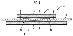
- the membrane-electrode structure 1a comprises a solid polymer electrolyte membrane 2, a pair of catalyst layers 3 and 4 that sandwich the solid polymer electrolyte membrane 2, and a pair of porous diffusion layers 5 and 6 laminated on both the catalyst layers 3 and 4.
- a catalyst layer 3 and a porous diffusion layer 5 form an electrode 7; and a catalyst layer 4 and a porous diffusion layer 6 form an electrode 8.
- the solid polymer electrolyte membrane 2 is formed to be larger than the catalyst layers 3 and 4, and the catalyst layers 3 and 4 are laminated to position in the inner circumference side than the outer circumferential edge of the solid polymer electrolyte membrane 2.
- One face of the solid polymer electrolyte membrane 2 is coated with a catalyst layer 4, and an adhesive support layer 9 that is adhered to the solid polymer electrolyte membrane 2 and supports the solid polymer electrolyte membrane 2.
- the adhesive support layer 9 is formed on the entire outer circumference side of the catalyst layer 4, and the catalyst layer 4 and the adhesive support layer 9 are coated with the porous diffusion layers 6.
- the portion that extends outwardly from the outer circumferential edge of the catalyst layer 3 is exposed.
- the catalyst layer 3 is formed to be larger than the catalyst layer 4, and the outer circumferential edge of the catalyst layer 4 is positioned in the inner circumference side than the outer circumferential edge of the catalyst layer 3, with sandwiching the solid polymer electrolyte membrane 2.
- the catalyst layer 4 may be formed to be larger than the catalyst layer 3, and the outer circumferential edge of the catalyst layer 3 may be positioned in the inner circumference side than the outer circumferential edge of the catalyst layer 4, with sandwiching the solid polymer electrolyte membrane 2.
- the solid polymer electrolyte membrane 2 is formed of a polymer electrolyte such as a perfluoroalkylene sulfonic acid polymer compound (e.g., Nafion (trade name) manufactured by DuPont) and a sulfonated polyarylene compound, and has a dry membrane thickness of, for example, 50 ⁇ m.
- a polymer electrolyte such as a perfluoroalkylene sulfonic acid polymer compound (e.g., Nafion (trade name) manufactured by DuPont) and a sulfonated polyarylene compound, and has a dry membrane thickness of, for example, 50 ⁇ m.
- the catalyst layers 3 and 4 are formed of catalyst particles and an ion-conductive binder.
- the ion-conductive binder the above-described polymer electrolyte is used.
- the porous diffusion layers 5 and 6 are formed of carbon paper and a backing layer (not shown) on the carbon paper.
- the backing layer is, for example, a 4:6 (ratio by weight) mixture of carbon black and polytetrafluoroethylene particles, and the catalyst layers 3 and 4 are formed on the backing layer.
- the adhesive support layer 9 is formed of an adhesive that has fluorine atoms in the molecular structure thereof. It is preferable that the adhesive contains a polysiloxane compound and a molecule that has at least two alkenyl groups, and cures when the alkenyl groups cross-link with the polysiloxane compound. It is also preferable that the adhesive has a tensile elongation at break of 150% or more after curing.
- Examples of such adhesives include an adhesive produced by mixing and agitating 100 parts by weight of the polymer represented by the following formula (1) (viscosity: 4.4 Pa ⁇ s; average molecular weight: 16,500; quantity of vinyl groups: 0.012 mol/100 g); 4 parts by weight of organo-hydrogen polysiloxane (CR-100 (trade name) manufactured by Kaneka Corporation); 8 parts by weight of a plasticizer (PAO-5010 (trade name) manufactured by Idemitsu Petrochemical Co., Ltd.); 12 parts by weight of fumed silica (manufactured by Tosoh Silica Corporation); and 3 parts by weight of organo-silane (KBM-303 (trade name) manufactured by Shin-Etsu Chemical Co., Ltd.); and defoaming; to which bis(1,3-divinyl-1,1,3,3-tetramethyl disiloxane)-platinum catalyst is added as a reaction catalyst so that the content of platinum is 5 ⁇ 10 -4 equivalent weights to the number
- adhesives is an adhesive produced by mixing and agitating 100 parts by weight of methyl(3,3,3-trifluoropropyl)polysiloxane of which both ends of the molecular chain are blocked by dimethylvinylsiloxy groups (viscosity: 1.0 Pa ⁇ s; content of vinyl groups bonded to silicon atoms: 1.0% by weight); 3.5 parts by weight of dimethylhydrogensiloxy(3,3,3-trifluoropropyl)polysiloxane of which both ends of the molecular chain are blocked by dimethylhydrogensiloxy groups (viscosity: 0.01 Pa ⁇ s; content of vinyl groups bonded to silicon atoms: 0.5% by weight); and 0.01 parts by weight of ferrocene; and defoaming; to which bis(1,3-divinyl-1,1,3,3-tetramethyl disiloxane)-platinum catalyst is added as a reaction catalyst so that the ratio by weight of platinum to methyl(3,3,3-
- membrane-electrode structures 1a and 1b are produced as follows:
- a mold having a maximum height R max of surface roughness within a range between 5 and 50 ⁇ m is pressed under heating against the region where the adhesive support layer 9 is formed throughout the entire outer circumference side of the region to form the catalyst layer 4 on the side of the solid polymer electrolyte membrane 2 where the catalyst layer 4 is formed.
- the surface pattern of the mold is transferred, and irregularity having a maximum height R max of surface roughness within a range between 3 and 20 ⁇ m is formed on the region where the adhesive support layer 9 of the solid polymer electrolyte membrane 2 is formed.
- catalyst particles wherein platinum particles are supported by carbon black are evenly dispersed in an ion-conductive binder consisting of the polymer electrolyte solution to prepare a catalyst paste.
- porous diffusion layer 5 is formed in the size within the size of the inner circumference side of the outer circumferential edge of the solid polymer electrolyte membrane 2, and the porous diffusion layer 6 is formed in the same size as the solid polymer electrolyte membrane 2.
- the catalyst paste is applied onto the entire surface of the backing layer of the porous diffusion layer 5, and dried to form a catalyst layer 3.
- the adhesive is applied to the entire circumference of the portion to become the outer circumference side of the catalyst layer 4 to form an adhesive support layer 9.
- the catalyst paste is applied to the inner circumference side of the adhesive support layer 9, and dried to form the catalyst layer 4.
- the catalyst layer 4 is formed in the size within the size of the inner circumference side of the outer circumferential edge of the catalyst layer 3.
- the catalyst layer 3 is formed in the size within the size of the inner circumference side of the outer circumferential edge of the catalyst layer 4.
- the porous diffusion layer 5 having the catalyst layer 3 formed thereon, and the porous diffusion layer 6 having the catalyst layer 4 formed thereon and the adhesive support layer 9 formed on the entire circumference side of the catalyst layer 4 are laminated with the polymer electrolyte membrane 2 at the sides having the catalyst layers 3 and 4, respectively, and compressed under heating.
- the catalyst layers 3 and 4 are bonded to the solid polymer electrolyte membrane 2 and integrated to form the membrane-electrode structures 1a and 1b.
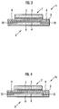
- the membrane-electrode structure 1c of this embodiment has the same constitution as the membrane-electrode structure 1a shown in FIG. 1, except that the adhesive that constitutes the adhesive support layer 9 is permeated into the porous diffusion layer 6 in the region where the porous diffusion layer 6 coats the adhesive support layer 9 to form an adhesive-permeated layer 10.
- the adhesive is permeated into the porous diffusion layer 6 in the filling rate to the void portion of the porous diffusion layer 6 within a range between 30 and 100%.
- the adhesive support layer 9 and the porous diffusion layer 6 are integrated through the adhesive-permeated layer 10.
- the catalyst layer 3 is formed to be larger than the catalyst layer 4, and the outer circumferential edge of the catalyst layer 4 is positioned on the inner circumference side than the outer circumferential edge of the catalyst layer 3, with sandwiching the solid polymer electrolyte membrane 2.
- the catalyst layer 4 may be formed to be larger than the catalyst layer 3, and the outer circumferential edge of the catalyst layer 3 is positioned on the inner circumference side than the outer circumferential edge of the catalyst layer 4, with sandwiching the solid polymer electrolyte membrane 2.
- Examples of the adhesives include an adhesive produced by mixing and agitating 100 parts by weight of the polymer represented by the following formula (1) (viscosity: 4.4 Pa ⁇ s; average molecular weight: 16,500; quantity of vinyl groups: 0.012 mol/100 g); 5 parts by weight of organo-hydrogen polysiloxane (CR-100 (trade name) manufactured by Kaneka Corporation); 8 parts by weight of a plasticizer (PAO-5010 (trade name) manufactured by Idemitsu Petrochemical Co., Ltd.); 12 parts by weight of fumed silica (manufactured by Tosoh Silica Corporation); and 3 parts by weight of organo-silane (KBM-303 (trade name) manufactured by Shin-Etsu Chemical Co., Ltd.); and defoaming; to which bis(1,3-divinyl-1,1,3,3-tetramethyl disiloxane)-platinum catalyst is added as a reaction catalyst so that the content of platinum is 5 ⁇ 10 -4 equivalent weights
- adhesives is an adhesive produced by mixing and agitating 100 parts by weight of methyl(3,3,3-trifluoropropyl)polysiloxane of which both ends of the molecular chain are blocked by dimethylvinylsiloxy groups (viscosity: 1.0 Pa ⁇ s; content of vinyl groups bonded to silicon atoms: 1.0% by weight); 3.5 parts by weight of dimethylhydrogensiloxy(3,3,3-trifluoropropyl)polysiloxane of which both ends of the molecular chain are blocked by dimethylhydrogensiloxy groups (viscosity: 0.01 Pa ⁇ s; content of vinyl groups bonded to silicon atoms: 0.5% by weight); and 0.01 parts by weight of ferrocene; and defoaming; to which bis(1,3-divinyl-1,1,3,3-tetramethyl disiloxane)-platinum catalyst is added as a reaction catalyst so that the ratio by weight of platinum to methyl (3,3,3-
- the adhesive support layer 9 may be formed on the entire circumference side of the catalyst layer 4, and a gap may be formed between the outer circumferential edge of the catalyst layer 4 and the inner circumferential edge of the adhesive support layer 9.
- the porous diffusion layer 5 may be larger than the catalyst layer 3, and may have, for example, the same as the porous diffusion layers 2.
- the adhesive support layer 9 may be formed throughout the entire outer circumference side of the catalyst layer 3 on the other face, which may be coated with the catalyst layer 3 and the adhesive support layer 9.
- the adhesive support layer 9 may coat at least a part of the solid polymer electrolyte membrane 2 extended outwardly from the outer circumferential edge of the catalyst layer 3, and is not required to coat the entire face.
- the electrode 7 is made to be a fuel electrode (anode), and a reducing gas such as hydrogen and methanol is introduced into the catalyst layer 3 through the porous diffusion layer 5;
- the electrode 8 is made to be an oxygen electrode (cathode), and an oxidizing gas such as air and oxygen is introduced into the catalyst layer 4 through the porous diffusion layer 6.
- the protons react with the oxidizing gas and electrons introduced into the catalyst layer 4 to form water by the action of the catalyst contained in the catalyst layer 4. Therefore, by connecting the fuel electrode to the oxygen electrode through a conductive wire, a circuit for transporting the electrons produced in the fuel electrode to the oxygen electrode is formed to abstract electric current, and the membrane-electrode structures 1a, 1b, 1c, and 1d can be used as a fuel cell.
- an adhesive was first prepared by mixing and agitating 100 parts by weight of the polymer represented by the following formula (1) (viscosity: 4.4 Pa ⁇ s; average molecular weight: 16,500; quantity of vinyl groups: 0.012 mol/100 g); 4 parts by weight of organo-hydrogen polysiloxane (CR-100 (trade name) manufactured by Kaneka Corporation); 8 parts by weight of a plasticizer (PAO-5010 (trade name) manufactured by Idemitsu Petrochemical Co., Ltd.); 12 parts by weight of fumed silica (manufactured by Tosoh Silica Corporation); and 3 parts by weight of organo-silane (KBM-303 (trade name) manufactured by Shin-Etsu Chemical Co., Ltd.); defoaming; and adding a xylene solution (8.3 ⁇ 10 -5 mol/ ⁇ l) of bis(1,3-divinyl-1,1,3,3-tetramethyl disiloxane)-platinum catalyst as a reaction catalyst so
- the tensile elongation at break of the above-described adhesive, measured in accordance with JIS K 6301 was 210%.
- a sulfonated polyarylene compound was prepared by adding concentrated sulfuric acid to a polyarylene compound represented by the following formula (2).
- n:m 0.5 to 100:99.5 to 0, and 1 denotes an integer of 1 or greater.
- sulfonated polyarylene compound used herein means a sulfonated product of a polymer having a structure represented by the following formula: (where -X- denotes a single bond or a divalent organic group; -W- denotes a divalent electron-attracting group; -T- denotes a divalent organic group; each of R1 to R8 denotes a fluorine atom, hydrogen atom, alkyl group, aryl group or allyl group, which may be identical to or different from each other; p denotes a number from 0.5 to 100; q denotes a number from 99.5 to 0; r denotes an integer from 0 to 10; and s denotes an integer from 1 to 100.)
- Examples of the above-described divalent electron-attracting groups may include groups such as -CO-, -CONH-. -(CF 2 ) p - (where p is an integer from 1 to 10), -C(CF 3 ) 2 -, -COO-, -SO- or -SO 2 -.
- the polyarylene compound represented by the formula (2) was prepared by the following procedures.
- the polymerization solution was diluted with tetrahydrofuran, solidified with hydrochloric acid/methanol, and recovered.
- the recovered product was repeatedly washed with methanol, and dissolved in tetrahydrofuran.
- the solution was subjected to reprecipitation from methanol for purification, and the precipitated polymer was dried in vacuo to obtain a polyarylene compound represented by the formula (2)(yield: 96%).
- the sulfonation of the polyarylene compound represented by the formula (2) was carried out by adding 96% sulfuric acid to the polyarylene compound, and stirring the mixture for 24 hours in a nitrogen flow.
- the obtained solution was poured into a large quantity of ion-exchanged water to precipitate the polymer, the polymer was repeatedly washed until the pH of the washing water becomes 5, and dried to obtain a sulfonated polyarylene compound of an ion-exchange capacity of 2.0 meq/g (yield: 96%).
- the sulfonated polyarylene compound was dissolved in N-methylpyrrolidone to prepare a polymer electrolyte solution, a membrane was formed from the polymer electrolyte solution by the casting method, and the membrane was dried to prepare a solid polymer electrolyte membrane 2 of a dry membrane thickness of 50 ⁇ m.
- a ion-conductive polymer binder solution e.g., Nafion (trade name) manufactured by DuPont
- a slurry prepared by evenly dispersing the mixture obtained by mixing carbon black and polytetrafluoroethylene (PTFE) particles at a weight ratio of 4 : 6 in ethylene glycol was applied onto a side of carbon paper and dried to form a backing layer, and a porous diffusion layers 5 and 6 consisting of the carbon paper and the backing layer were formed.
- the porous diffusion layer 5 had a size within the size of the inner circumference side of the outer circumferential edge of the solid polymer electrolyte membrane 2
- the porous diffusion layer 6 had a size same as the size of the solid polymer electrolyte membrane 2.
- the catalyst paste was applied onto the entire surface of the backing layer of the porous diffusion layer 5 by screen printing so that the platinum content becomes 0.5 mg/cm 2 , heated at 60°C for 10 minutes, heated under a reduced pressure at 120°C for 15 minutes, and dried to form a catalyst layer 3.
- the adhesive was applied to the entire circumference of the portion to be the outer circumference side of the catalyst layer 4 of the porous diffusion layer 6 to form an adhesive support layer 9.
- the catalyst paste was applied onto the inner circumference side of the adhesive support layer 9 formed on the porous diffusion layer 6 by screen printing so that the platinum content becomes 0.5 mg/cm 2 , heated at 60°C for 10 minutes, heated under a reduced pressure at 120°C for 15 minutes, and dried to form a catalyst layer 4.
- the catalyst layer 4 had a size within the inner circumference side of the outer circumferential edge of the catalyst layer 3.
- the solid polymer electrolyte membrane 2 was sandwiched between the catalyst layers 3 and 4, and integrated with the catalyst layers 3 and 4 by hot-pressing at 150°C and 2.5 MPa for 15 minutes to produce a membrane-electrode structure 1a shown in FIG. 1.
- the membrane-electrode structure 11a has the same constitution as the membrane-electrode structure 1a other than the following aspects:
- the test piece was held between punching sheets made of polytetrafluoroethylene, and the cycles of the operations to immerse the test piece in water of 95°C for 5 hours applying a load of a surface pressure of 490 kPa, and to dry it at 100°C for 5 hours, were repeated. After each of 10, 50, 100, and 200 cycles of the above operations, the peel strength of the test piece was obtained in the same manner as in the above-described initial strength. The results are shown in Table 1.
- an adhesive was prepared in the same manner as in Example 1 except that the quantity of compounded fumed silica was 20 parts by weight.
- the tensile elongation at break after curing of the above adhesive measured in the same manner as in Example 1 was 150%.
- a membrane-electrode structure 1a shown in FIG. 1 and a membrane-electrode structure 11a shown in FIG. 5 were produced in the same manner as in Example 1 except that the adhesive prepared in this example was used in place of the adhesive used in Example 1, and the stress concentration of the solid polymer electrolyte membrane 2 was examined in the same manner as in Example 1. The results are shown in Table 2.
- an adhesive was produced by mixing and agitating 100 parts by weight of methyl(3,3,3-trifluoropropyl)polysiloxane of which both ends of the molecular chain are blocked by dimethylvinylsiloxy groups (viscosity: 1.0 Pa ⁇ s; content of vinyl groups bonded to silicon atoms: 1.0% by weight); 3.5 parts by weight of dimethylhydrogensiloxy(3,3,3-trifluoropropyl)polysiloxane of which both ends of the molecular chain are blocked by dimethylhydrogensiloxy groups (viscosity: 0.01 Pa ⁇ s; content of vinyl groups bonded to silicon atoms: 0.5% by weight); and 0.01 parts by weight of ferrocene; and defoaming; to which a xylene solution (8.3 ⁇ 10 -5 mol/ ⁇ l) of bis(1,3-divinyl-1,1,3,3-tetramethyl disiloxane)-platinum catalyst was added as a reaction
- a membrane-electrode structure 1a shown in FIG. 1 and a membrane-electrode structure 11a shown in FIG. 5 were produced in the same manner as in Example 1 except that the adhesive prepared in this example was used in place of the adhesive used in Example 1, and the peel strength of the adhesive support layer 9 was measured in the same manner as in Example 1. The results are shown in Table 1.
- an adhesive was prepared in the same manner as in Example 1 except that an isobutylene resin that contains no fluorine atoms in the molecule thereof (Epion (trade name) manufactured by Kaneka Corporation) was used in place of the polymer represented by the formula (1).
- a membrane-electrode structure 1a shown in FIG. 1 and a membrane-electrode structure 11a shown in FIG. 5 were produced in the same manner as in Example 1 except that the adhesive prepared in this example was used in place of the adhesive used in Example 1, and the peel strength of the adhesive support layer 9 was measured in the same manner as in Example 1. The results are shown in Table 1.
- a membrane-electrode structure 1a shown in FIG. 1 and a membrane-electrode structure 11a shown in FIG. 5 were produced in the same manner as in Example 1 except that a silicone-based adhesive not containing fluorine atoms in the molecule (1209 (trade name) manufactured by Three Bond Co., Ltd.) was used in place of the adhesive used in Example 1, and the adhesive support layer 9 was measured in the same manner as in Example 1. The results are shown in Table 1.
- a membrane-electrode structure 1a shown in FIG. 1 and a membrane-electrode structure 11a shown in FIG. 5 were produced in the same manner as in Example 1 except that a silicone-based adhesive not containing fluorine atoms in the molecule (1211 (trade name) manufactured by Three Bond Co., Ltd.) was used in place of the adhesive used in Example 1, and the adhesive support layer 9 was measured in the same manner as in Example 1. The results are shown in Table 1.
- an adhesive was prepared in the same manner as in Example 1 except that the quantity of compounded fumed silica was 30 parts by weight.
- the tensile elongation at break after curing of the above adhesive measured in the same manner as in Example 1 was 120%.
- a membrane-electrode structure 1a shown in FIG. 1 and a membrane-electrode structure 11a shown in FIG. 5 were produced in the same manner as in Example 1 except that the adhesive prepared in this comparative example was used in place of the adhesive used in Example 1, and the stress concentration of the solid polymer electrolyte membrane 2 was examined in the same manner as in Example 1. The results are shown in Table 2.
- an adhesive was prepared in the same manner as in Example 1 except that the quantity of compounded fumed silica was 40 parts by weight.
- the tensile elongation at break after curing of the above adhesive measured in the same manner as in Example 1 was 90%.
- a membrane-electrode structure 1a shown in FIG. 1 and a membrane-electrode structure 11a shown in FIG. 5 were produced in the same manner as in Example 1 except that the adhesive prepared in this comparative example was used in place of the adhesive used in Example 1, and the stress concentration of the solid polymer electrolyte membrane 2 was examined in the same manner as in Example 1. The results are shown in Table 2.
- the adhesive support layer 9 consisting of an adhesive that contains fluorine molecules in the molecules thereof (Examples 1 and 3) has a high peel strength even after the treatments assuming a high-temperature high-humidity environment during the operation of the fuel cell are repeated for 200 cycles, and a high adhesive strength can be obtained.
- the adhesive support layer 9 consisting of an adhesive that contains no fluorine molecules in the molecules thereof (Comparative Examples 1 to 3) has a low initial peel strength, and easily peels off by the above-described, and sufficient adhesive strength cannot be obtained.
- the membrane formed by the casting method from the polymer electrolyte solution same as in Example 1 was dried in an oven at a temperature of 80°C for 2 hours to prepare a solid polymer electrolyte membrane 2 of a dry membrane thickness of 50 ⁇ m.
- the obtained solid polymer electrolyte membrane 2 was immersed in distilled water for 24 hours to remove impurities, and dried.
- the membrane-electrode structure 1a shown in FIG. 1 and the membrane-electrode structure 11a shown in FIG. 5 were produced in the same manner as in Example 1 except that irregularity (not shown) of the maximum height R max of surface roughness within a range between 3 and 20 ⁇ m on the region where the adhesive support layer 9 of the solid polymer electrolyte membrane 2 is formed using the solid polymer electrolyte membrane 2 prepared in this embodiment, in place of the solid polymer electrolyte membrane 2 used in Example 1.
- the above-described irregularity was formed by pressing a mold having "wrinkle" of which the maximum height R max of the surface roughness was within a range between 5 and 50 ⁇ m against the region where the adhesive support layer 9 was formed on the entire circumference of the outer circumference side of the region where the catalyst layer 4 was formed on the side where the catalyst layer 4 of the solid polymer electrolyte membrane 2, at 40°C and 10 MPa for 10 minutes.
- the pattern of the "wrinkle" of the mold was transferred, and the irregularity was formed on the region where the adhesive support layer 9 of the solid polymer electrolyte membrane 2 was formed.
- the peel strength (initial strength) of the adhesive support layer 9 in the membrane-electrode structure 11a obtained in this example was measured in the same manner as in Example 1, and the result was 208 gf/cm. Therefore, according to the producing method of the present invention, it is obvious that an adhesive support layer 9 having a higher adhesive strength than the adhesive support layer 9 of the membrane-electrode structures 1a and 11a obtained in Examples 1 and 3, respectively can be obtained.
- an adhesive was first prepared in the same manner as in Example 1, except that the quantity of the organo-hydrogen polysiloxane used was 5 parts by weight.
- a membrane-electrode structure 1c shown in FIG. 3 was produced in the same manner as in Example 1, except that the catalyst paste was heated to dry at 120°C for 30 minutes under a reduced pressure when the catalyst layer 3 was formed, and the above-described adhesive was permeated in the region where the porous diffusion layer 6 coats the adhesive support layer 9 to form an adhesive permeated layer 10 when the adhesive support layer 9 was formed.
- the above-described adhesive was applied onto the entire circumference of the portion to be the outer circumference side of the catalyst layer 4 of the porous diffusion layer 6 using a screen-printing machine (MT-750T (trade name) manufactured by Microtek Inc.) to form the adhesive support layer 9.
- MT-750T trade name
- Microtek Inc. a screen-printing machine
- the above-described adhesive was permeated into the region where the porous diffusion layer 6 coats the adhesive support layer 9 using a stainless-steel (SUS 304) screen of a wire diameter of 30 ⁇ m and an opening of 250 mesh/inch in the above-described screen-printing machine, so that the filling rate to the void portion of the porous diffusion layer 6 was 40%, to form an adhesive permeated layer 10.
- the membrane-electrode structure 11b has the same constitution as the constitution of the membrane-electrode structure 1c other than the following aspects:
- the membrane-electrode structure 1c shown in FIG. 3 and the membrane-electrode structure 11b shown in FIG. 6 were produced in the same manner as in Example 5, except that the above-described adhesive was permeated into the region where the porous diffusion layer 6 coats the adhesive support layer 9 using a polyester screen of a wire diameter of 45 ⁇ m and an opening of 150 mesh/inch in the same screen-printing machine as that used in Example 5, so that the filling rate to the void portion of the porous diffusion layer 6 was 60%, to form an adhesive permeated layer 10, and the withstand pressure strength of the porous diffusion layer 6 was measured in the same manner as in Example 5. The results are shown in FIG. 7.
- the membrane-electrode structure 1c shown in FIG. 3 and the membrane-electrode structure 11b shown in FIG. 6 were produced in the same manner as in Example 5, except that the above-described adhesive was permeated into the region where the porous diffusion layer 6 coats the adhesive support layer 9 using a polyester screen of a wire diameter of 55 ⁇ m and an opening of 100 mesh/inch in the same screen-printing machine as that used in Example 5, so that the filling rate to the void portion of the porous diffusion layer 6 was 70%, to form an adhesive permeated layer 10, and the withstand pressure strength of the porous diffusion layer 6 was measured in the same manner as in Example 5. The results are shown in FIG. 7.
- the membrane-electrode structure 11b having the adhesive-permeated layer 10 (Examples 5 to 7) has a small plastic deformation due to load, excels in withstand pressure strength, and the plastic deformation or damage of the porous diffusion layer 6 can be prevented.
- the present invention can be utilized in a solid polymer electrolyte fuel cell used in electrical and transport apparatuses, in particular as a membrane-electrode structure of an in-vehicle polymer electrolyte fuel cell.
Landscapes
- Life Sciences & Earth Sciences (AREA)
- Engineering & Computer Science (AREA)
- Manufacturing & Machinery (AREA)
- Sustainable Development (AREA)
- Sustainable Energy (AREA)
- Chemical & Material Sciences (AREA)
- Chemical Kinetics & Catalysis (AREA)
- Electrochemistry (AREA)
- General Chemical & Material Sciences (AREA)
- Fuel Cell (AREA)
- Inert Electrodes (AREA)
Abstract
Description


| Peel strength of adhesive support layer 9 (gf/cm) | |||||
| Example 1 | Example 3 | Comparative Example 1 | Comparative Example 2 | Comparative Example 3 | |
| Initial strength | 158 | 122 | 52 | 31 | 84 |
| After 10 cycles | 141 | 101 | Peeled off | Peeled off | 40 |
| After 50 cycles | 131 | 90 | peeled off | Peeled off | Peeled off |
| After 100 cycles | 117 | 83 | Peeled off | Peeled off | Peeled off |
| After 200 cycles | 98 | 75 | Peeled off | Peeled off | Peeled off |
| Tensile elongation at break of | |||||
| Example 1 | Example 2 | Example 3 | Comparative Example 4 | Comparative Example 5 | |
| Tensile elongation at break (%) | 210 | 150 | 250 | 120 | 90 |
| After 10 cycles | ○ | ○ | ○ | ○ | ○ |
| After 50 cycles | ○ | ○ | ○ | ○ | × |
| After 100 cycles | ○ | ○ | ○ | × | × |
| After 200 cycles | ○ | ○ | ○ | × | × |
| ○: Cracked ×: Not cracked |
Claims (13)
- A membrane-electrode structure comprising a pair of electrodes that comprise catalyst layers, and a solid polymer electrolyte membrane sandwiched by said catalyst layers of both electrodes, characterized in that:said catalyst layers are positioned in the inner circumference side than the outer circumferential edge of said solid polymer electrolyte membrane;at least one face of said solid polymer electrolyte membrane is coated with said catalyst layers, and an adhesive support layer that is formed on said catalyst layers and throughout the entire circumference of the outer circumferential side of said catalyst layers, adheres to said solid polymer electrolyte membrane, and supports said solid polymer electrolyte membrane; andsaid adhesive support layer is formed of an adhesive having fluorine atoms in the molecular structure.
- The membrane-electrode structure according to claim 1, characterized in that said adhesive has a tensile elongation at break of 150% or more after curing.
- The membrane-electrode structure according to claim 1, characterized in that said adhesive contains a polysiloxane compound and a molecule that has at least two alkenyl groups.
- The membrane-electrode structure according to claim 1, characterized in comprising a diffusion layer that coats said catalyst layers and said adhesive support layer.
- The membrane-electrode structure according to claim 4, characterized in that said diffusion layer is formed of a porous material, and said adhesive support layer is integrated with said diffusion layer through an adhesive-permeated layer formed by permeating said adhesive into said diffusion layer.
- The membrane-electrode structure according to claim 5, characterized in that said adhesive-permeated layer is formed by permeating said adhesive into said diffusion layer in the region where said diffusion layer formed of a porous material coats said adhesive support layer, within a range wherein the filling factor to the void portion of said diffusion layer is 30 to 100%.
- The membrane-electrode structure according to claim 1, characterized in that at least a part of the outer circumferential edge of said one catalyst layer is positioned on the portion different from the outer circumferential edge of the other catalyst layer, with sandwiching said solid polymer electrolyte membrane.
- The membrane-electrode structure according to claim 7, characterized in that the outer circumferential edge of said one catalyst layer is positioned in the inner circumference side than the outer circumferential edge of the other catalyst layer, with sandwiching said solid polymer electrolyte membrane.
- A polymer electrolyte fuel cell characterized in using a membrane-electrode structure comprising a pair of electrodes that comprise catalyst layers, and a solid polymer electrolyte membrane sandwiched by said catalyst layers of both electrodes wherein:said catalyst layers are positioned in the inner circumference side than the outer circumferential edge of said solid polymer electrolyte membrane;at least one face of said solid polymer electrolyte membrane is coated with said catalyst layers and an adhesive support layer; andsaid adhesive support layer is formed of an adhesive having fluorine atoms in the molecular structure, is formed throughout the entire circumference of the outer circumferential side of said catalyst layers, adheres to said solid polymer electrolyte membrane, and supports said solid polymer electrolyte membrane.
- An electrical apparatus characterized in that using a polymer electrolyte fuel cell comprising a membrane-electrode structure comprising a pair of electrodes that comprise catalyst layers, and a solid polymer electrolyte membrane sandwiched by said catalyst layers of both electrodes wherein:said catalyst layers are positioned in the inner circumference side than the outer circumferential edge of said solid polymer electrolyte membrane;at least one face of said solid polymer electrolyte membrane is coated with said catalyst layers and an adhesive support layer; andsaid adhesive support layer is formed of an adhesive having fluorine atoms in the molecular structure, is formed throughout the entire circumference of the outer circumferential side of said catalyst layers, adheres to said solid polymer electrolyte membrane, and supports said solid polymer electrolyte membrane.
- A transport apparatus characterized in using a polymer electrolyte fuel cell comprising a membrane-electrode structure comprising a pair of electrodes that comprise catalyst layers, and a solid polymer electrolyte membrane sandwiched by said catalyst layers of both electrodes wherein:said catalyst layers are positioned in the inner circumference side than the outer circumferential edge of said solid polymer electrolyte membrane;at least one face of said solid polymer electrolyte membrane is coated with said catalyst layers and an adhesive support layer; andsaid adhesive support layer is formed of an adhesive having fluorine atoms in the molecular structure, is formed throughout the entire circumference of the outer circumferential side of said catalyst layers, adheres to said solid polymer electrolyte membrane, and supports said solid polymer electrolyte membrane.
- A method for producing a membrane-electrode structure comprising a pair of electrodes that comprise catalyst layers, and a solid polymer electrolyte membrane sandwiched by said catalyst layers of both electrodes wherein:at least one face of said solid polymer electrolyte membrane is coated with said catalyst layers and an adhesive support layer; and said adhesive support layer is formed throughout the entire circumference of the outer circumferential side of said catalyst layers, adheres to said solid polymer electrolyte membrane, and supports said solid polymer electrolyte membrane; characterized in comprising the steps of:said catalyst layers are positioned in the inner circumference side than the outer circumferential edge of said solid polymer electrolyte membrane;forming a solid polymer electrolyte membrane from a polymer electrolyte solutions;forming irregularity having a maximum height Rmax of surface roughness within a range between 3 and 20 µm on the area of said solid polymer electrolyte membrane coated by said adhesive support layer;forming said adhesive support layer by applying an adhesive having fluorine atoms in the molecular structure onto a sheet backing, and drying; andbonding said adhesive support layer formed on said sheet backing on the area where said irregularity of said solid polymer electrolyte membrane has been formed by pressing under heating.
- The method for producing a membrane-electrode structure according to claim 12, characterized in that said adhesive contains a polysiloxane compound and a molecule that has at least two alkenyl groups.
Applications Claiming Priority (13)
| Application Number | Priority Date | Filing Date | Title |
|---|---|---|---|
| JP2002313741 | 2002-10-29 | ||
| JP2002313740 | 2002-10-29 | ||
| JP2002313740 | 2002-10-29 | ||
| JP2002313741 | 2002-10-29 | ||
| JP2002364579 | 2002-12-17 | ||
| JP2002364579 | 2002-12-17 | ||
| JP2003360614 | 2003-10-21 | ||
| JP2003360241A JP4421260B2 (en) | 2002-10-29 | 2003-10-21 | Method for manufacturing membrane-electrode structure |
| JP2003360242 | 2003-10-21 | ||
| JP2003360241 | 2003-10-21 | ||
| JP2003360614A JP4421261B2 (en) | 2002-12-17 | 2003-10-21 | Method for manufacturing membrane-electrode structure |
| JP2003360242A JP4426248B2 (en) | 2002-10-29 | 2003-10-21 | Membrane-electrode structure |
| PCT/JP2003/013777 WO2004040681A1 (en) | 2002-10-29 | 2003-10-28 | Membrane-electrode structure and method for producing same |
Publications (3)
| Publication Number | Publication Date |
|---|---|
| EP1569291A1 true EP1569291A1 (en) | 2005-08-31 |
| EP1569291A4 EP1569291A4 (en) | 2008-01-02 |
| EP1569291B1 EP1569291B1 (en) | 2012-11-21 |
Family
ID=32234483
Family Applications (1)
| Application Number | Title | Priority Date | Filing Date |
|---|---|---|---|
| EP03758994A Expired - Lifetime EP1569291B1 (en) | 2002-10-29 | 2003-10-28 | Membrane-electrode structure and method for producing same |
Country Status (3)
| Country | Link |
|---|---|
| US (1) | US20050181267A1 (en) |
| EP (1) | EP1569291B1 (en) |
| WO (1) | WO2004040681A1 (en) |
Cited By (2)
| Publication number | Priority date | Publication date | Assignee | Title |
|---|---|---|---|---|
| EP1619739A3 (en) * | 2004-07-20 | 2007-02-28 | Honda Motor Co., Ltd. | Membrane-electrode structure for solid polymer fuel cell and solid polymer fuel cell |
| DE112005002440B4 (en) * | 2004-10-07 | 2010-03-18 | General Motors Corp. (N.D.Ges.D. Staates Delaware), Detroit | Method of making a modular electrode assembly for PEM fuel cells |
Families Citing this family (19)
| Publication number | Priority date | Publication date | Assignee | Title |
|---|---|---|---|---|
| TWI251954B (en) * | 2003-07-29 | 2006-03-21 | Ind Tech Res Inst | Flat fuel cell assembly and fabrication thereof |
| US20060127738A1 (en) * | 2004-12-13 | 2006-06-15 | Bhaskar Sompalli | Design, method and process for unitized mea |
| US20060280981A1 (en) * | 2005-06-02 | 2006-12-14 | Polyfuel, Inc. | Polymer electrolyte membrane having an improved dimensional stability |
| JP4882314B2 (en) * | 2005-08-31 | 2012-02-22 | 日産自動車株式会社 | Electrolyte membrane-electrode assembly and method for producing the same |
| US7722979B2 (en) * | 2005-10-14 | 2010-05-25 | Gm Global Technology Operations, Inc. | Fuel cells with hydrophobic diffusion medium |
| KR100767531B1 (en) * | 2006-10-31 | 2007-10-17 | 현대자동차주식회사 | A membrane-electrode assembly which is reduced an interface resistance between a catalystic electrode layer and an electrolyte membrane |
| WO2008056661A1 (en) * | 2006-11-07 | 2008-05-15 | Panasonic Corporation | Film-film reinforcing film assembly, film-catalyst layer assembly, film-electrode assembly, and polymer electrolyte fuel cell |
| JP4550798B2 (en) * | 2006-12-25 | 2010-09-22 | シャープ株式会社 | Solid polymer electrolyte fuel cell and method for producing the same |
| WO2008090778A1 (en) * | 2007-01-22 | 2008-07-31 | Panasonic Corporation | Film-film reinforcing member bonded body, film-catalyst layer bonded body, film-electrode bonded body, and polyelectrolyte type fuel cell |
| CN101542801B (en) * | 2007-01-29 | 2012-04-18 | 松下电器产业株式会社 | Film-film reinforcing member bonded body, film-catalyst layer bonded body, film-electrode bonded body, and polyelectrolyte type fuel cell |
| WO2008126350A1 (en) * | 2007-03-14 | 2008-10-23 | Panasonic Corporation | Membrane-membrane reinforcing member assembly, membrane-catalyst layer assembly, membrane-electrode assembly, polymer electrolyte fuel cell, and process for producing membrane-electrode assembly |
| US8993135B2 (en) * | 2007-11-01 | 2015-03-31 | Honeywell International Inc. | Fuel cell stack for hydrogen fuel power generator |
| US9029038B2 (en) * | 2007-11-01 | 2015-05-12 | Honeywell International Inc. | Method of forming a fuel cell stack |
| JP5396029B2 (en) * | 2008-02-21 | 2014-01-22 | 東海ゴム工業株式会社 | FUEL CELL CELL, FUEL CELL, AND METHOD FOR PRODUCING FUEL CELL CELL |
| US8735017B2 (en) * | 2010-03-10 | 2014-05-27 | Samsung Sdi Co., Ltd | Membrane-electrode assembly for fuel cell, method of manufacturing membrane-electrode assembly for fuel cell, and fuel cell system |
| JP5615875B2 (en) * | 2012-01-16 | 2014-10-29 | 本田技研工業株式会社 | Electrolyte membrane / electrode structure with resin frame for fuel cells |
| WO2016016288A1 (en) * | 2014-08-01 | 2016-02-04 | Siemens Aktiengesellschaft | Fuel cell assembly and method for operating a fuel cell assembly |
| JP6344229B2 (en) * | 2014-12-17 | 2018-06-20 | 株式会社デンソー | Gas sensor and manufacturing method thereof |
| EP3472885A4 (en) * | 2016-06-15 | 2020-06-17 | 3M Innovative Properties Company | Membrane electrode assembly component and method of making an assembly |
Citations (3)
| Publication number | Priority date | Publication date | Assignee | Title |
|---|---|---|---|---|
| WO1997023916A2 (en) * | 1995-12-22 | 1997-07-03 | Hoechst Research & Technology Deutschland Gmbh & Co. Kg | Material composites and the continuous production thereof |
| US6165634A (en) * | 1998-10-21 | 2000-12-26 | International Fuel Cells Llc | Fuel cell with improved sealing between individual membrane assemblies and plate assemblies |
| EP1289042A2 (en) * | 2001-08-29 | 2003-03-05 | Honda Giken Kogyo Kabushiki Kaisha | Membrane electrode assembly and fuel cell |
Family Cites Families (12)
| Publication number | Priority date | Publication date | Assignee | Title |
|---|---|---|---|---|
| US5176966A (en) * | 1990-11-19 | 1993-01-05 | Ballard Power Systems Inc. | Fuel cell membrane electrode and seal assembly |
| JPH056771A (en) * | 1991-06-18 | 1993-01-14 | Fuji Electric Co Ltd | Fuel cell |
| JPH07220742A (en) * | 1994-01-27 | 1995-08-18 | Matsushita Electric Ind Co Ltd | Solid high polymer electrolyte fuel cell and manufacture of electrode-ion exchange film connector for this fuel cell |
| JP3256649B2 (en) * | 1995-08-29 | 2002-02-12 | 三菱電機株式会社 | Method for manufacturing polymer electrolyte fuel cell and polymer electrolyte fuel cell |
| DE19627024B4 (en) * | 1996-07-04 | 2007-08-02 | Dieffenbacher Gmbh + Co. Kg | Method and plant for the continuous folding and gluing of veneer sheets to veneer layer boards |
| JP3805495B2 (en) * | 1996-09-24 | 2006-08-02 | 松下電器産業株式会社 | Polymer electrolyte fuel cell |
| US6261711B1 (en) * | 1999-09-14 | 2001-07-17 | Plug Power Inc. | Sealing system for fuel cells |
| JP4543267B2 (en) | 2000-05-17 | 2010-09-15 | 株式会社スリーボンド | Curable composition for fuel cell |
| JP5057002B2 (en) * | 2000-10-06 | 2012-10-24 | 株式会社スリーボンド | Primer composition for adhesion of fuel cell carbon separator |
| US7217471B2 (en) * | 2002-05-17 | 2007-05-15 | 3M Innovative Properties Company | Membrane electrode assembly with compression control gasket |
| US6979383B2 (en) * | 2002-12-17 | 2005-12-27 | 3M Innovative Properties Company | One-step method of bonding and sealing a fuel cell membrane electrode assembly |
| US7132191B2 (en) * | 2003-09-17 | 2006-11-07 | General Motors Corporation | Addressing one MEA failure mode by controlling MEA catalyst layer overlap |
-
2003
- 2003-10-28 WO PCT/JP2003/013777 patent/WO2004040681A1/en active Application Filing
- 2003-10-28 EP EP03758994A patent/EP1569291B1/en not_active Expired - Lifetime
- 2003-10-28 US US10/505,442 patent/US20050181267A1/en not_active Abandoned
Patent Citations (3)
| Publication number | Priority date | Publication date | Assignee | Title |
|---|---|---|---|---|
| WO1997023916A2 (en) * | 1995-12-22 | 1997-07-03 | Hoechst Research & Technology Deutschland Gmbh & Co. Kg | Material composites and the continuous production thereof |
| US6165634A (en) * | 1998-10-21 | 2000-12-26 | International Fuel Cells Llc | Fuel cell with improved sealing between individual membrane assemblies and plate assemblies |
| EP1289042A2 (en) * | 2001-08-29 | 2003-03-05 | Honda Giken Kogyo Kabushiki Kaisha | Membrane electrode assembly and fuel cell |
Non-Patent Citations (1)
| Title |
|---|
| See also references of WO2004040681A1 * |
Cited By (2)
| Publication number | Priority date | Publication date | Assignee | Title |
|---|---|---|---|---|
| EP1619739A3 (en) * | 2004-07-20 | 2007-02-28 | Honda Motor Co., Ltd. | Membrane-electrode structure for solid polymer fuel cell and solid polymer fuel cell |
| DE112005002440B4 (en) * | 2004-10-07 | 2010-03-18 | General Motors Corp. (N.D.Ges.D. Staates Delaware), Detroit | Method of making a modular electrode assembly for PEM fuel cells |
Also Published As
| Publication number | Publication date |
|---|---|
| WO2004040681A1 (en) | 2004-05-13 |
| EP1569291B1 (en) | 2012-11-21 |
| US20050181267A1 (en) | 2005-08-18 |
| EP1569291A4 (en) | 2008-01-02 |
Similar Documents
| Publication | Publication Date | Title |
|---|---|---|
| EP1569291B1 (en) | Membrane-electrode structure and method for producing same | |
| US8304134B2 (en) | Polymer electrolyte composition, polymer electrolyte membrane, membrane electrode assembly and solid polymer electrolyte-based fuel cell | |
| JP5334273B2 (en) | Fluorine polymer electrolyte membrane | |
| US20130052564A1 (en) | Polymer electrolyte membrane, membrane-electrode assembly, and solid polymer fuel cell | |
| EP1429403B1 (en) | Membrane-electrode structure and polymer electrolyte fuel cell using the same | |
| EP3951017A1 (en) | Multilayer electrolyte membrane, membrane electrode assembly, water electrolysis-type hydrogen generator and method for producing multilayer electrolyte membrane | |
| EP1739780A1 (en) | Solid electrolyte, membrane and electrode assembly, and fuel cell | |
| EP2131431B1 (en) | Membrane-electrode bonding agent, proton conducting membrane with bonding layer, membrane-electrode assembly, solid polymer fuel cell, and method for producing membrane-electrode assembly | |
| KR20100018579A (en) | Assembly of membrane, electrode, gas diffusion layer and gasket, method for producing the same, and solid polymer fuel cell | |
| US7306876B2 (en) | Method for producing membrane-electrode structure and polymer electrolyte fuel cell | |
| JP4587383B2 (en) | Electrolyte membrane and method for producing the same | |
| EP2104166A1 (en) | Membrane-electrode assembly | |
| US20040096717A1 (en) | Solid polymer type fuel cell | |
| US20080038614A1 (en) | Proton-conducting electrolyte membrane, production process thereof, and membrane-electrode assembly and fuel cell using the same | |
| EP1420473B1 (en) | Electrode structure for polymer electrolyte fuel cells, and polymer electrolyte fuel cell using the same | |
| JP2006066391A (en) | Polymer electrolyte fuel cell | |
| US20060275637A1 (en) | Electrolyte membrane and preparing method thereof | |
| EP2128920A1 (en) | Proton conductive film, membrane-electrode assembly, and solid polymer electrolyte fuel cell | |
| JP4392222B2 (en) | Method for manufacturing membrane-electrode structure | |
| JP4421261B2 (en) | Method for manufacturing membrane-electrode structure | |
| JP4426248B2 (en) | Membrane-electrode structure | |
| JP4421260B2 (en) | Method for manufacturing membrane-electrode structure | |
| EP2339678A1 (en) | Polymer electrolyte membrane and laminate thereof | |
| JP4811575B2 (en) | Curable resin composition for electrolyte membrane, method for producing electrolyte membrane, and method for producing electrolyte membrane / electrode assembly | |
| JP4720090B2 (en) | Sulfonic acid group-containing polymer electrolyte membrane and article using the same |
Legal Events
| Date | Code | Title | Description |
|---|---|---|---|
| PUAI | Public reference made under article 153(3) epc to a published international application that has entered the european phase |
Free format text: ORIGINAL CODE: 0009012 |
|
| 17P | Request for examination filed |
Effective date: 20040810 |
|
| AK | Designated contracting states |
Kind code of ref document: A1 Designated state(s): AT BE BG CH CY CZ DE DK EE ES FI FR GB GR HU IE IT LI LU MC NL PT RO SE SI SK TR |
|
| RBV | Designated contracting states (corrected) |
Designated state(s): DE GB |
|
| A4 | Supplementary search report drawn up and despatched |
Effective date: 20071130 |
|
| 17Q | First examination report despatched |
Effective date: 20081229 |
|
| GRAP | Despatch of communication of intention to grant a patent |
Free format text: ORIGINAL CODE: EPIDOSNIGR1 |
|
| GRAS | Grant fee paid |
Free format text: ORIGINAL CODE: EPIDOSNIGR3 |
|
| RIN1 | Information on inventor provided before grant (corrected) |
Inventor name: NANAUMI,MASAAKI C/OK.KAISHA HONDAGIJUTSU KENKYUSHO Inventor name: MITSUTA,NAOKI C/O K.KAISHA HONDA GIJUTSU KENKYUSHO Inventor name: SHINKAI,HIROSHIC/OK.KAISHA HONDA GIJUTSU KENKYUSHO |
|
| GRAA | (expected) grant |
Free format text: ORIGINAL CODE: 0009210 |
|
| RAP1 | Party data changed (applicant data changed or rights of an application transferred) |
Owner name: HONDA MOTOR CO., LTD. |
|
| AK | Designated contracting states |
Kind code of ref document: B1 Designated state(s): DE GB |
|
| REG | Reference to a national code |
Ref country code: GB Ref legal event code: FG4D |
|
| REG | Reference to a national code |
Ref country code: DE Ref legal event code: R096 Ref document number: 60342655 Country of ref document: DE Effective date: 20130117 |
|
| RIN2 | Information on inventor provided after grant (corrected) |
Inventor name: NANAUMI,MASAAKI Inventor name: MITSUTA,NAOKI Inventor name: SHINKAI,HIROSHI |
|
| PLBE | No opposition filed within time limit |
Free format text: ORIGINAL CODE: 0009261 |
|
| STAA | Information on the status of an ep patent application or granted ep patent |
Free format text: STATUS: NO OPPOSITION FILED WITHIN TIME LIMIT |
|
| REG | Reference to a national code |
Ref country code: DE Ref legal event code: R084 Ref document number: 60342655 Country of ref document: DE Effective date: 20130802 |
|
| 26N | No opposition filed |
Effective date: 20130822 |
|
| REG | Reference to a national code |
Ref country code: DE Ref legal event code: R097 Ref document number: 60342655 Country of ref document: DE Effective date: 20130822 |
|
| GBPC | Gb: european patent ceased through non-payment of renewal fee |
Effective date: 20131028 |
|
| PG25 | Lapsed in a contracting state [announced via postgrant information from national office to epo] |
Ref country code: GB Free format text: LAPSE BECAUSE OF NON-PAYMENT OF DUE FEES Effective date: 20131028 |
|
| PGFP | Annual fee paid to national office [announced via postgrant information from national office to epo] |
Ref country code: DE Payment date: 20181016 Year of fee payment: 16 |
|
| REG | Reference to a national code |
Ref country code: DE Ref legal event code: R119 Ref document number: 60342655 Country of ref document: DE |
|
| PG25 | Lapsed in a contracting state [announced via postgrant information from national office to epo] |
Ref country code: DE Free format text: LAPSE BECAUSE OF NON-PAYMENT OF DUE FEES Effective date: 20200501 |