EP1569002B1 - Electricity Meter System - Google Patents
Electricity Meter System Download PDFInfo
- Publication number
- EP1569002B1 EP1569002B1 EP05002754A EP05002754A EP1569002B1 EP 1569002 B1 EP1569002 B1 EP 1569002B1 EP 05002754 A EP05002754 A EP 05002754A EP 05002754 A EP05002754 A EP 05002754A EP 1569002 B1 EP1569002 B1 EP 1569002B1
- Authority
- EP
- European Patent Office
- Prior art keywords
- electricity meter
- adapter
- meter
- phase
- fastening surface
- Prior art date
- Legal status (The legal status is an assumption and is not a legal conclusion. Google has not performed a legal analysis and makes no representation as to the accuracy of the status listed.)
- Expired - Lifetime
Links
- 230000005611 electricity Effects 0.000 title claims abstract description 81
- 238000003780 insertion Methods 0.000 claims description 10
- 230000037431 insertion Effects 0.000 claims description 10
- 238000006073 displacement reaction Methods 0.000 claims description 3
- UQDJGEHQDNVPGU-UHFFFAOYSA-N serine phosphoethanolamine Chemical compound [NH3+]CCOP([O-])(=O)OCC([NH3+])C([O-])=O UQDJGEHQDNVPGU-UHFFFAOYSA-N 0.000 claims 2
- 230000015572 biosynthetic process Effects 0.000 description 7
- 238000005755 formation reaction Methods 0.000 description 7
- 230000001154 acute effect Effects 0.000 description 3
- 239000004020 conductor Substances 0.000 description 2
- 241000722921 Tulipa gesneriana Species 0.000 description 1
- 239000000969 carrier Substances 0.000 description 1
- 238000004891 communication Methods 0.000 description 1
- 230000000295 complement effect Effects 0.000 description 1
- 239000011810 insulating material Substances 0.000 description 1
- 239000000463 material Substances 0.000 description 1
- 238000000034 method Methods 0.000 description 1
- 230000007935 neutral effect Effects 0.000 description 1
- 238000007493 shaping process Methods 0.000 description 1
Images
Classifications
-
- G—PHYSICS
- G01—MEASURING; TESTING
- G01R—MEASURING ELECTRIC VARIABLES; MEASURING MAGNETIC VARIABLES
- G01R22/00—Arrangements for measuring time integral of electric power or current, e.g. electricity meters
- G01R22/06—Arrangements for measuring time integral of electric power or current, e.g. electricity meters by electronic methods
- G01R22/061—Details of electronic electricity meters
- G01R22/065—Details of electronic electricity meters related to mechanical aspects
Definitions
- This power meter assembly has an adapter which is mounted on a counter cross in a counter space and placed on an electric meter.
- This electronic power meter has on its attachment side a number of phases corresponding number of connector pins that can be configured as a tab or terminal lugs, via which the current per phase to the counter and is derived from the counter.
- These connector pins engage in the mounted state of the electricity meter in fixed, formed as tulips contacts, of which each one of each phase with an access conductor and the other of each phase are connected to the associated output line to the consumer.
- the assembly process is reversed: By mounting the contact bridges are moved, wherein a first contact the terminal pins is generated with the fixed contact pieces, so that during assembly for a certain period of time, a current flow is achieved both via the contact bridge and via the electricity meter.
- the electricity meter has at its attachment surface feet, which are placed upon insertion on each an associated support; These supports have inclined surfaces, so that in the further course of assembly of the electricity meter is sunk into the adapter.
- the L-shaped feet arranged on the fastening surface have one perpendicular to the fastening surface at the free end of each free leg of the L-shape extending Anformung that touches when placing the L-shape on the supports in the direction of a movement for final assembly of the electricity meter executed end face of the support and at least partially covered, so that pivoting of the electricity meter about an axis which is transverse to the direction of movement of the electricity meter , is prevented.
- the length of each insertion opening for the feet in the direction of movement of the electricity meter is adapted exactly to the length of the free leg of the L-shape.
- edges facing the mounting surface of the free legs of the L-shape are arranged approximately parallel to the inclined surface on the end faces of the supports.
- the wall thickness of the wall of the adapter to the insertion opening tapers at each insertion opening, wherein the chamfer runs approximately parallel to the mounting surface facing edges of the free legs.
- a further embodiment of the invention can be formed on the mounting side of the electricity meter per a perpendicular thereto extending nose-like projection, also called driver, which engages when placing the electricity meter on the adapter in a first recess on the bridge; at the bridge is an additional one mounted second recess into which the connector pin protrudes on the power meter, wherein the connector pin and the second recess are dimensioned so that both remain permanently free of each other, so that when moving into the end position and back only the projection moves the bridge and an electrically conductive connection between the bridge and the connector pin is prevented.
- the electricity meter may have feet and a driver for the contact bridge of each phase, wherein the feet are formed only L-shaped.
- the feet may be provided with the Anformung and the electricity meter with the driver.
- feet can be used with the Anformung, wherein the driver is omitted from the electricity meter.
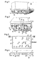
- the electricity meter assembly 10 shown in FIG. 1 has a power meter 11, which may be formed as an electronic electricity meter, and an adapter 12; Of this adapter 12, only the housing cover 13 with integrally formed locking arms 14 and 15 and some internals (see below) are visible. Of the locking arms 14 and 15 only those are numbered at the one narrow end face; the cover 13 also has further latching arms, via which a cup-shaped housing lower part (see FIG. 5) can be locked in place on the cover or vice versa.
- Fixed contact pieces 16, 17 are fixed on the inner surface of the lower housing part for each individual phase (the other fixed contact pieces are only partially visible and also not numbered).
- These contacts are U-shaped, wherein the legs 18 and 19 of the contact piece 16 in a plane with the corresponding legs (not numbered in detail) of the contact piece 17; the open sides of the contact pieces 16 and 17 are directed to the power meter 11 out.
- a bridge 20 is arranged, which is displaceable in the direction of the longer side surfaces of the electricity meter or the longer side edges of the lid 13 and in the direction of the current flow in the adapter 11.
- This bridge 20 is made of elongated ribbon conductor material and has on its side facing the electricity meter 11 edge a first recess 21 into which a driving pin 22, which is arranged on the mounting surface of the electricity meter 11 and accordingly consists of insulating material, fits, if the electricity meter is placed on the adapter 12.
- the bridge 20 further has a second recess 23 into which a terminal pin 24 protrudes when the power meter 11 is mounted;
- the dimensions of the second recess 23 are chosen so that the connector pin 24, which is also to be referred to as a terminal lug, at no stage of the assembly comes into contact with the bridge 20.
- the driving pin 22 is also referred to as a projection or short driver. The driver 22 is thus positively coupled to the first recess, whereas between the terminal lug 24 and the inner contour of the second recess 23 is always maintained a sufficient insulating distance.
- FIG 3 shows a plan view of the mounting surface of the electricity meter 11, each with two terminal lugs 24, 25; or 26, 27 and 28, 29, wherein the in-line terminal lugs 24, 25; 26, 27; 28 and 29 each belong to one phase.
- the lines run parallel to the longer side surface of the electricity meter or to the longitudinal edge of the mounting surface.
- connection lug 30 is provided, which with the 0 or. Neutral contact piece comes into communication.
- the distance of the driver 22 of the adjacent terminal lug 24 is dimensioned so that between the first and second recess 21, 23 of the bridge 20, a pin 33 stops, which is to be dimensioned so that it is 20 when moving the bridge by the driver 22 not deformed.
- FIG. 4 shows the view according to the direction of arrow IV-IV of the electricity meter 11 in the lower region, ie in the region of the mounting surface 40.
- a circumferential bar 41 is provided, and at the longer bar sections 42 and 43 are feet 44, 45; 46, 47 formed, of which in the drawing Fig. 4 only the feet 44 and 45 are visible; the other feet 46, 47 are hidden.
- Each foot 44, 45; 46, 47 initially has an L-shape with a first leg 46A, 47A, which runs perpendicular to the bar 41 or mounting surface 40, to which a respective second leg 48 or 49, which runs essentially parallel to the mounting surface 40, connect, wherein the legs 48 and 49 project in the same direction, ie in the direction of the final assembly position.
- At the free ends of the legs 48, 49 close to projections 50 and 51, which extend perpendicular to the legs 48 and 49 and perpendicular to the mounting surface 40.
- Edges 52 and 53 of the legs 48, 49 form an acute angle with the mounting surface or with the free edge of the strip 41st
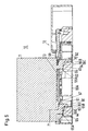
- the power meter assembly is composed of the power meter 11 and the adapter 12, wherein the adapter 12 has a housing lower part 60, which is cup-shaped and can be latched to the lid 13 via the latching arms 14 and 15.
- the lid 13 has slot-like through openings 61 and 62 for each foot 44, 45; 46, 47; 5, the openings 61 and 62 serve to insert the feet 44 and 45.
- the length of the insertion openings 61 and 62 corresponds to the length of the legs 48, 49.
- the insertion openings for the feet 46, 47 are shown in FIG. 5 concealed, but have the same shape as that for the feet 44, 45th
- a number of feet corresponding number (four here) of supports 63, 64 is formed, which correspond to the supports 28, 50a, 50b of DE 10 2004 003 050.2.
- the end faces 65 and 66 are formed as well as the end faces of said supports in DE 10 2004 003 050.2.
- the mounting of the electricity meter 11 is done as follows:
- the electricity meter 11 is placed perpendicular to its mounting surface on the adapter, the feet 44, 45; 46, 47 are inserted through the openings 61, 62 formed as slots, until the outer edges of the legs 48, 49 touch the section 65a or 66a of each support. Then, the electricity meter 11 is moved so that the feet 44, 45; 46, 47 on the sections 65a, 65c and 66a, 66c slide and thereby the power meter 11 is lowered perpendicular to its mounting surface and thus spent in final assembly position.
- the wall thickness of the lid tapers in the region of the slots 61 and 62 toward and into this opening, whereby an inclined surface 67 and 68 is formed which is parallel to the edge 52 and 53, so that when inserting and lowering the electricity meter 11, the edges 52, 53 slide along the inclined surfaces 67, 68 and so engage behind the lid 13 and are also guided downwards.
- the formations 50 and 51 abut against the end faces 69, 70 running perpendicular to the inner surface of the housing bottom 60A and pointing towards the final assembly position, so that in the pre-assembly position a pivoting about an axis perpendicular to the plane of the drawing z. B. in the area of the feet 45, 47, is prevented, because the formation 50 bears against the end face 69.
- the end face 69 obstructs the foot or the formation 50, as can be clearly seen from the drawing in FIG. 5, and of course also applies to the formation of the foot 46.
- the illustrated bridge 20 is free with one end of the contact piece 16 and the contact piece 17 is in the region of the recess 23, so that an electrically conductive connection between the contact pieces 16, 17 via the bridge 20 not more is given.
- the disassembly is then carried out so that the electricity meter is moved to the pre-assembly position shown in Figure 5, wherein the feet slide on the inclined surfaces 65C, 66C, whereby the carrier 20, the bridge 20 is moved; the bridge 20 bridges during the lifting movement of the electricity meter 11, the contacts 16 before the terminal lugs 24, 25 come free from the contact pieces 16, 17, which also applies to the other phases.
- the carriers could be dispensed with, so that the second recess 23 corresponds in dimensions to the first recess 21, so that the contact lugs 24 fit precisely into these recesses. In this case, the recess 21 would not be required.
- Another embodiment could be that the formations 50, 51 are omitted; In this case, the drivers 22, 31, 32 would be present and accordingly also the first and second recesses 20, 23 on each bridge 20.
Landscapes
- Engineering & Computer Science (AREA)
- Power Engineering (AREA)
- Physics & Mathematics (AREA)
- General Physics & Mathematics (AREA)
- Connector Housings Or Holding Contact Members (AREA)
- Escalators And Moving Walkways (AREA)
- Preparation Of Compounds By Using Micro-Organisms (AREA)
- Measurement Of Resistance Or Impedance (AREA)
Abstract
Description
Die Erfindung betrifft eine Stromzähleranordnung.The invention relates to a power meter arrangement.
In DE 203 13 421 U ist eine Stronzählenanordnung beschrieben, bei der ein Elektrizitätszähler steck- und verschiebbar auf einer Zählertragplatte angeordnet ist. Dieser Elektrizitätszähler ist mit Einhängewinkelstücken bestickt, die die Einhängeschlitze an der Zählertragplatte hintergreifen, wobei die elektrische Verbindung des Elektrizitätszählers zwischen dem Versorgungsnetz und der Kundenanlage über am Elektrizitätszähler angeordneten Steckverbindungsteile, die die Zählertragplatte durchdringen und die hinter der Zählertragplatte angeordneten Komplementären Steckverbindungsteile Kontaktieren, hergestellt wird.In DE 203 13 421 U a Stronzählenanordnung is described, in which an electricity meter plug and is slidably mounted on a counter support plate. This electricity meter is embroidered with Einhängewinkelstücken, which engage behind the Einhängeschlitze on the meter support plate, wherein the electrical connection of the electricity meter between the supply network and the customer system via arranged on the electricity meter connector parts which penetrate the meter support plate and arranged behind the meter support plate complementary connector parts, is made.
Eine weitere Stromzähleranordnung ist in der nicht vorveröffentlichten Schrift DE 10 2004 003 050.2 vom 20.01.2004 (EP 1 557 677 A) beschrieben. Diese Stromzähleranordnung besitzt einen Adapter, der auf einem Zählerkreuz in einem Zählerplatz befestigt und auf den ein elektrischer Stromzähler aufgesetzt werden. Dieser elektronische Stromzähler besitzt an seiner Befestigungsseite eine der Anzahl der Phasen entsprechende Anzahl von Anschlusssteckerstiften, die als Flachstecker oder Anschlussfahnen ausgebildet sein können, über die der Strom pro Phase zum Zähler hin und vom Zähler abgeleitet wird. Diese Anschlusssteckerstifte greifen im montierten Zustand des Stromzählers in feststehende, als Tulpen ausgebildete Kontaktstücke ein, von denen jeweils eines jeder Phase mit einem Zugangsleiter und das andere jeder Phase mit dem zugehörigen Abgangsieiter zum Verbraucher verbunden sind. Damit beim Auswechseln eines Stromzählers der Stromfluss zum Verbraucher nicht unterbrochen wird, befindet sich innerhalb des Adapters jeweils eine Kontaktbrücke pro Phase, die im montierten Zustand des Stromzählers frei von den Kontaktstücken ist, so dass der Strom ausschließlich über den Stromzähler fließt. Jeweils eines der Anschlusskontaktstifte am Stromzähler ist formschlüssig mit der zugehörigen Kontaktbrücke verbunden, so dass beim Demontieren des Stromzählers die Kontaktbrücke verschoben wird, derart, dass, bevor die Anschlusskontaktstifte des Stromzählers frei von den feststehenden Kontaktstücken gelangen, die Kontaktbrücke ein Kurzschließen der zugehörigen Kontaktstücke bewirkt, so dass auf diese Weise bei der Demontage eine Stromunterbrechung zum Verbraucher vermieden ist. Der Montagevorgang erfolgt umgekehrt: Durch die Montage werden die Kontaktbrücken verschoben, wobei eine Kontaktierung zunächst der Anschlusskontaktstifte mit den feststehenden Kontaktstücken erzeugt wird, so dass bei der Montage während eines bestimmten Zeitraumes ein Stromfluss sowohl über die Kontaktbrücke als auch über den Stromzähler erreicht wird.Another power meter arrangement is described in the
Eine ähnliche Stromzähleranordnung ist auch aus der nicht vorveröffentlichten Schrift EP 1 462 808 A bekannt.A similar current meter arrangement is also known from the unpublished document EP 1 462 808 A.
Bei der Ausführung nach der DE 10 2004 003 050.2 besitzt der Stromzähler an seiner Befestigungsfläche Füße, die beim Einsetzen auf jeweils eine zugehörige Stütze aufgesetzt werden; diese Stützen besitzen Schrägflächen, so dass im weiteren Verlauf der Montage der Stromzähler in den Adapter eingesenkt wird.In the embodiment according to
Es hat sich dabei herausgestellt, dass bei entsprechender sehr ungünstiger Handhabung der Stromzähler in eine Stellung, in der die Befestigungsfläche des Stromzählers einen spitzen Winkel mit der Befestigungsfläche am Adapter einnimmt, verschwenkt werden kann, die einen Anschlusskontaktstifte mit der zugehörigen Kontaktbrücke in Berührung gelangen können, so dass die anderen Anschlusskontaktstifte an Spannung gelegt sind; im ungünstigsten Falle passt die Hand einer Bedienperson dazwischen, so dass diese potentialführenden Anschlusskontaktstifte berührt werden können, so dass eine Gefährdung der Bedienperson gegeben sein kann.It has been found that with appropriate very unfavorable handling of the electricity meter in a position in which the mounting surface of the electricity meter occupies an acute angle with the mounting surface on the adapter can be pivoted, which can reach a terminal contact pins with the associated contact bridge in touch, such that the other terminal pins are connected to voltage; in the worst case fits the hand of an operator between them, so that these potential-carrying terminal pins can be touched, so that a risk to the operator may be present.
Aufgabe der Erfindung ist es, die Stromzähleranordnung der eingangs genannten Art soweit weiter zu verbessern, dass auch in einem ungünstigen Fall eine Berührung spannungsführender Teile durch eine Bedienperson ausgeschlossen ist.The object of the invention is to further improve the power meter assembly of the type mentioned so far that even in an unfavorable case, a contact of live parts is excluded by an operator.
Diese Aufgabe wird erfindungsgemäß gelöst durch die Merkmale der Ansprüche 1 und 2.This object is achieved by the features of claims 1 and 2.
Erfindungsgemäß also weisen die an der Befestigungsfläche angeordneten L-förmigen Füße am freien Ende jedes freien Schenkels der L-Form je eine senkrecht zur Befestigungsfläche verlaufende Anformung auf, die beim Aufsetzen der L-Form auf die Stützen die in Richtung einer Bewegung zur Endmontage des Stromzählers hingerichtete Stirnfläche der Stütze berührt und zumindest teilweise überdeckt, so dass ein Verschwenken des Stromzählers um eine Achse, die quer zur Bewegungsrichtung des Stromzählers verläuft, verhindert ist.Thus, according to the invention, the L-shaped feet arranged on the fastening surface have one perpendicular to the fastening surface at the free end of each free leg of the L-shape extending Anformung that touches when placing the L-shape on the supports in the direction of a movement for final assembly of the electricity meter executed end face of the support and at least partially covered, so that pivoting of the electricity meter about an axis which is transverse to the direction of movement of the electricity meter , is prevented.
Dadurch, dass die An- oder Ausformung an der entsprechenden Kante oder Fläche der Stütze anlegt, ist ein Herausdrehen des Stromzählers um eine quer zur Stromführungsrichtung im Stromzähler aus dieser eine Vormontagestellung des Stromzählers einnehmenden Lage nicht mehr möglich, weil aufgrund der Verschwenkung die an der Stirnfläche der jeweiligen Stütze anliegende Kante am freien Ende der Anformung eine Kreisbewegung durchführen würde, die durch die entsprechende Stirnfläche der Stütze behindert ist.Due to the fact that the forming or shaping abuts on the corresponding edge or surface of the support, unscrewing the electricity meter is no longer possible around a location transversely to the current-carrying direction in the electricity meter from this pre-assembly position of the electricity meter, because due to the pivoting on the end surface abutting the respective support edge at the free end of the Anformung would perform a circular motion, which is hindered by the corresponding end face of the support.
Gemäß einer weiteren vorteilhaften Ausführungsform der Erfindung ist die Länge jeder Einführöffnung für die Füße in Bewegungsrichtung des Stromzählers genau auf die Länge des freien Schenkels der L-Form angepasst. Damit wird bei einer leichten Verschiebung des Stromzählers gegenüber dem Adapter das freie Ende des freien Schenkels der L-Form sofort hinter die benachbarte Kante der Einführöffnung gelangen, so dass ein Herausziehen nicht mehr möglich ist.According to a further advantageous embodiment of the invention, the length of each insertion opening for the feet in the direction of movement of the electricity meter is adapted exactly to the length of the free leg of the L-shape. Thus, with a slight displacement of the electricity meter relative to the adapter, the free end of the free leg of the L-shape immediately behind the adjacent edge of the insertion reach, so that pulling out is no longer possible.
Gemäß einer weiteren vorteilhaften Ausgestaltung der Erfindung sind die zur Befestigungsfläche hinweisenden Kanten der freien Schenkel der L-Form etwa parallel zur Schrägfläche an den Stirnseiten der Stützen angeordnet.According to a further advantageous embodiment of the invention, the edges facing the mounting surface of the free legs of the L-shape are arranged approximately parallel to the inclined surface on the end faces of the supports.
Zusätzlich ist an jeder Einführöffnung die Wandstärke der Wandung des Adapters zur Einführöffnung hin verjüngt, wobei die Abschrägung etwa parallel zur zur Befestigungsfläche hinweisenden Kanten der freien Schenkel verläuft.In addition, the wall thickness of the wall of the adapter to the insertion opening tapers at each insertion opening, wherein the chamfer runs approximately parallel to the mounting surface facing edges of the free legs.
Gemäß einer weiteren Ausgestaltung der Erfindung kann an der Befestigungsseite des Stromzählers je ein senkrecht dazu verlaufender nasenartiger Vorsprung, auch Mitnehmer genannt, angeformt sein, der beim Aufsetzen des Stromzählers auf den Adapter in eine erste Aussparung an der Brücke eingreift; an der Brücke ist zusätzlich eine zweite Aussparung angebracht, in die der Anschlusssteckerstift am Stromzähler hineinragt, wobei der Anschlusssteckerstift und die zweite Aussparung so bemessen sind, dass beide dauernd frei voneinander bleiben, so dass beim Verbringen in die Endstellung und zurück lediglich der Vorsprung die Brücke verschiebt und eine elektrisch leitende Verbindung zwischen der Brücke und dem Anschlusssteckerstift verhindert ist.According to a further embodiment of the invention can be formed on the mounting side of the electricity meter per a perpendicular thereto extending nose-like projection, also called driver, which engages when placing the electricity meter on the adapter in a first recess on the bridge; at the bridge is an additional one mounted second recess into which the connector pin protrudes on the power meter, wherein the connector pin and the second recess are dimensioned so that both remain permanently free of each other, so that when moving into the end position and back only the projection moves the bridge and an electrically conductive connection between the bridge and the connector pin is prevented.
Weitere vorteilhafte Ausgestaltungen der Erfindung sind den weiteren Unteransprüchen zu entnehmen.Further advantageous embodiments of the invention can be found in the further subclaims.
Es bestehen insgesamt drei Möglichkeiten:
Der Stromzähler kann Füße aufweisen sowie einen Mitnehmer für die Kontaktbrücke jeder Phase, wobei die Füße lediglich L-förmig ausgebildet sind.There are three possibilities:
The electricity meter may have feet and a driver for the contact bridge of each phase, wherein the feet are formed only L-shaped.
In einer Ausführungsform können die Füße mit der Anformung und der Stromzähler mit dem Mitnehmer versehen sein.In one embodiment, the feet may be provided with the Anformung and the electricity meter with the driver.
In einer Ausführungsform können Füße mit der Anformung eingesetzt werden, wobei der Mitnehmer am Stromzähler weggelassen ist.In one embodiment, feet can be used with the Anformung, wherein the driver is omitted from the electricity meter.
Anhand der Zeichnungen, in der ein Ausführungsbeispiel der Erfindung dargestellt ist, sollen die Erfindung sowie weitere vorteilhafte Ausgestaltungen und Verbesserungen der Erfindung näher erläutert und beschrieben werden.Reference to the drawings, in which an embodiment of the invention is shown, the invention and further advantageous embodiments and improvements of the invention will be explained and described in detail.
Es zeigen
- Fig. 1
- eine perspektivische Ansicht einer Stromzähleranordnung, mit aufgeschnittenem Adapter,
- Fig. 2
- eine Vergrößerung aus der Ansicht gemäß Fig. 1,
- Fig. 3
- eine Aufsicht auf die Befestigungsseite des Stromzählers,
- Fig. 4
- eine Teilansicht des Stromzählers gemäß Pfeilrichtung IV-IV und
- Fig. 5
- eine Schnittansicht durch einen Stromzähler (dieser ist schematisch dargestellt) und den Adapter, wobei sich der Stromzähler in einer Vormontagestellung befindet.
- Fig. 1
- a perspective view of an electricity meter assembly, with cut adapter,
- Fig. 2
- an enlargement from the view of FIG. 1,
- Fig. 3
- a view of the mounting side of the electricity meter,
- Fig. 4
- a partial view of the electricity meter according to arrow IV-IV and
- Fig. 5
- a sectional view through an electricity meter (this is shown schematically) and the adapter, wherein the electricity meter is in a pre-assembly.
Die Stromzähleranordnung 10 gemäß Fig. 1 besitzt einen Stromzähler 11, der als elektronischer Stromzähler ausgebildet sein kann, und einen Adapter 12; von diesem Adapter 12 sind nur der Gehäusedeckel 13 mit daran angeformten Rastarmen 14 und 15 sowie einige Einbauten (siehe weiter unten) sichtbar. Von den Rastarmen 14 und 15 sind lediglich diejenigen an der einen Schmalstirnseite beziffert; der Deckel 13 besitzt noch weitere Rastarme, über die ein napfförmiges Gehäuseunterteil (siehe Fig. 5) am Deckel bzw. umgekehrt festgerastet werden kann. An der Innenfläche des Gehäuseunterteils sind feststehende Kontaktstücke 16, 17 für jede einzelne Phase fixiert (die anderen festen Kontaktstücke sind nur zum Teil sichtbar und ebenfalls nicht beziffert). Diese Kontaktstücke sind U-förmig ausgebildet, wobei die Schenkel 18 und 19 des Kontaktstückes 16 in einer Ebene mit den entsprechenden Schenkeln (nicht näher beziffert) des Kontaktstückes 17 liegen; die offenen Seiten der Kontaktstücke 16 und 17 sind zum Stromzähler 11 hin gerichtet. Innerhalb der jeweils zu einer Phase gehörenden Kontaktstücke 16 und 17 ist eine Brücke 20 angeordnet, die in Richtung der längeren Seitenflächen des Stromzählers bzw. der längeren Seitenkanten des Deckels 13 sowie in Richtung der Stromführung im Adapter 11 verschiebbar ist. Diese Brücke 20 ist aus langgestrecktem Flachbandleitermaterial hergestellt und besitzt an ihrer zum Stromzähler 11 hin weisenden Kante eine erste Aussparung 21, in die ein Mitnehmerzapfen 22, der an der Befestigungsfläche des Stromzählers 11 angeordnet ist und demgemäss aus isolierendem Material besteht, hineinpasst, wenn der Stromzähler auf den Adapter 12 aufgesetzt wird. Die Brücke 20 besitzt weiterhin eine zweite Aussparung 23, in die ein Anschlusssteckerstift 24 hineinragt bzw. eingreift, wenn der Stromzähler 11 montiert wird; die Abmessungen der zweiten Aussparung 23 sind dabei so wählen, dass der Anschlusssteckerstift 24, der auch als Anschlussfahne zu bezeichnen ist, in keinem Stadium der Montage in Berührung mit der Brücke 20 gelangt. Der Mitnehmerzapfen 22 ist auch als Vorsprung oder kurz Mitnehmer bezeichnet. Der Mitnehmer 22 ist somit formschlüssig mit der ersten Aussparung gekoppelt, wogegen zwischen der Anschlussfahne 24 und der Innenkontur der zweiten Aussparung 23 immer ein ausreichender isolierender Abstand eingehalten ist.The
Eine entsprechende Ausführungsform ist auch für alle anderen Phasen gegeben.A corresponding embodiment is also given for all other phases.
Die Fig. 3 zeigt eine Aufsicht auf die Befestigungsfläche des Stromzählers 11 mit je zwei Anschlussfahnen 24, 25; beziehungsweise 26, 27 und 28, 29, wobei die in einer Linie liegenden Anschlussfahnen 24, 25; 26, 27; 28 und 29 jeweils einer Phase zugehörig sind. Die Linien verlaufen parallel zur längeren Seitenfläche des Stromzählers bzw. zur Längskante der Befestigungsfläche.3 shows a plan view of the mounting surface of the
Zusätzlich ist eine Anschlussfahne 30 vorgesehen, die mit dem 0-bzw. Neutralleiterkontaktstück in Verbindung gelangt.In addition, a
Jeder Phase zugehörig ist je ein Mitnehmer 22, 31 und 32, die jeweils auf der gleichen Linie liegen wie die Anschlussfahnen 24, 25; 26, 27; 28, 29 für jede Phase. Der Abstand des Mitnehmers 22 von der benachbarten Anschlussfahne 24 ist so bemessen, dass zwischen der ersten und zweiten Aussparung 21, 23 der Brücke 20 ein Zapfen 33 stehen bleibt, der so zu bemessen ist, dass er sich beim Verschieben der Brücke 20 durch den Mitnehmer 22 nicht verformt.Each phase belonging to a
Die Fig. 4 zeigt die Ansicht gemäß Pfeilrichtung IV-IV des Stromzählers 11 im unteren Bereich, also im Bereich der Befestigungsfläche 40. Am Rand dieser Befestigungsfläche 40 ist eine umlaufende Leiste 41 vorgesehen, und an den längeren Leistenabschnitten 42 und 43 sind Füße 44, 45; 46, 47 angeformt, von denen in der Zeichnung Fig. 4 nur die Füße 44 und 45 sichtbar sind; die anderen Füße 46, 47 sind verdeckt. Jeder Fuß 44, 45; 46, 47 besitzt zunächst eine L-Form mit einem ersten Schenkel 46A, 47A, der senkrecht zur Leiste 41 bzw. Befestigungsfläche 40 verläuft, an dem je ein zweiter Schenkel 48 bzw. 49, der im wesentlichen parallel zur Befestigungsfläche 40 verläuft, anschließen, wobei die Schenkel 48 und 49 in gleiche Richtung, d.h. in Richtung der Endmontagestellung vorspringen. An den freien Enden der Schenkel 48, 49 schließen sich Anformungen 50 und 51 an, die senkrecht zu den Schenkeln 48 und 49 und senkrecht zur Befestigungsfläche 40 verlaufen. Die zur Befestigungsfläche 40 hinweisenden Kanten 52 und 53 der Schenkel 48, 49 bilden einen spitzen Winkel mit der Befestigungsfläche bzw. mit der freien Kante der Leiste 41.4 shows the view according to the direction of arrow IV-IV of the
Es sei nun Bezug genommen auf die Fig. 5.Reference is now made to FIG. 5.
Die Stromzähleranordnung setzt sich zusammen aus dem Stromzähler 11 und dem Adapter 12, wobei der Adapter 12 ein Gehäuseunterteil 60 aufweist, welches napfförmig ist und mit dem Deckel 13 über die Rastarme 14 und 15 verrastet werden kann.The power meter assembly is composed of the
Der Deckel 13 besitzt schlitzartige Durchstecköffnungen 61 und 62 für jeden Fuß 44, 45; 46, 47; in der Darstellung gemäß Fig. 5 dienen die Öffnungen 61 und 62 zum Einführen der Füße 44 und 45. Die Länge der Einführungsöffnungen 61 und 62 entspricht der Länge der Schenkel 48, 49. Die Durchstecköffnungen für die Füße 46, 47 sind in Fig. 5 verdeckt, besitzen aber die gleiche Form wie die für die Füße 44, 45.The
Auf der Innenfläche des Gehäuseunterteils ist eine der Anzahl der Füße entsprechende Anzahl (hier vier) von Stützen 63, 64 angeformt, die den Stützen 28, 50a, 50b der DE 10 2004 003 050.2 entsprechen. Die Stirnseiten 65 und 66 sind ebenso ausgebildet wie die Stirnseiten der genannten Stützen in der DE 10 2004 003 050.2. Die Stirnseiten 65 und 66 besitzen zwei Abschnitte 65a und 65b bzw. 66a und 66b, von denen die Abschnitte 65A und 66A einen größeren Abstand von der Innenfläche des Bodens 60A des Gehäuseunterteils 60 als die Abschnitte 65B, 66B einnehmen; zwischen den Abschnitten 65a, 65b bzw. 66a, 66b befindet sich je ein schrägverlaufender Abschnitt 65c und 66c, die die beiden Abschnitte 65a, 65b; 66a, 66b miteinander verbinden. Die Abschnitte 65c und 66c bilden mit der Innenfläche des Bodens 60a einen spitzen Winkel, wobei die Abschnitte 65c und 66c etwa parallel zu den Kanten 52, 53 der Schenkel 48, 49 verlaufen. Die Abschnitte 65B, 66B liegen bezogen auf die Abschnitte 65A, 66A in Richtung hin zur Endmontagestellung. Die Stirnseiten der Stützen können natürlich auch so ausgebildet sein wie in den Figuren 6 bis 8 der DE 10 2004 003 050.2 dargestellt.On the inner surface of the housing lower part a number of feet corresponding number (four here) of
Die Montage des Stromzählers 11 geschieht wie folgt:The mounting of the
Zunächst wird der Stromzähler 11 senkrecht zu seiner Befestigungsfläche auf den Adapter aufgesetzt, wobei die Füße 44, 45; 46, 47 durch die als Schlitze ausgebildeten Öffnungen 61, 62 hindurch gesteckt werden, solange, bis sich die Außenkanten der Schenkel 48, 49 auf den Abschnitt 65a bzw. 66a jeder Stütze aufsetzt. Sodann wird der Stromzähler 11 derart weiterbewegt, dass die Füße 44, 45; 46, 47 auf den Abschnitten 65a, 65c bzw. 66a, 66c gleiten und dadurch der Stromzähler 11 senkrecht zu seiner Befestigungsfläche abgesenkt und damit in Endmontagestellung verbracht wird. Die Wandstärke des Deckels verjüngt sich im Bereich der Schlitze 61 und 62 auf diese zu und in diese einmündend, wodurch eine Schrägfläche 67 bzw. 68 gebildet ist, die parallel zu der Kante 52 bzw. 53 verläuft, so dass beim Einschieben und Absenken des Stromzählers 11 die Kanten 52, 53 an den schrägen Flächen 67, 68 entlang gleiten und so den Deckel 13 hintergreifen und auch nach unten geführt werden.First, the
In der in der Fig. 5 gezeigten Vormontagestellung liegen die Ausformungen 50 und 51 an der senkrecht zur Innenfläche des Gehäusebodens 60A verlaufenden und zur Endmontagestellung hinweisenden Stirnflächen 69, 70 an, so dass in der Vormontagestellung eine Schwenkung um eine senkrecht zur Zeichenebene verlaufende Achse, die sich z. B. im Bereich der Füße 45, 47 befindet, verhindert wird, weil die Ausformung 50 gegen die Stirnfläche 69 anliegt. Wenn sich die Ausformung 50 beispielsweise auf einer Kreisbahn 71 bewegen sollte, dann behindert die Stirnfläche 69 den Fuß bzw. die Ausformung 50, wie aus der Zeichnung Fig. 5 klar ersichtlich ist und was natürlich auch für die Ausformung am Fuß 46 gilt.In the pre-assembly position shown in FIG. 5, the
Beim Absenken des Stromzählers 11 und danach beim Abgleiten auf den Abschnitten 65C und 66C gelangen die Mitnehmer 22, 31, 32 in ihre zugehörigen Aussparungen 21 jeder Brücke und verschieben dabei diese Brücken dergestalt, dass die Anschlussfahnen 24, 25; 26, 27; 28, 29 in die zugehörigen feststehenden Kontaktstücke 16, 17 einlaufen und mit diesen in elektrisch leitende Berührung gelangen, bevor die Brücken 20 frei von den Kontaktstücken 16 durch einfaches Herausziehen aus den Kontaktstücken 16 und die Kontaktstücke 17 in den Bereich der zweiten Aussparungen 23 gelangen, wodurch eine elektrisch leitende Verbindung zwischen den Kontaktstücken 16 und 17 über die Brücken 20 und eine elektrisch leitende Verbindung von den Kontaktstücken 16, 17 zu den zugehörigen Anschlussfahnen 24, 25 erreicht ist, so dass in diesem Zeitbereich der Strom sowohl über den Stromzähler 11 als auch über die Brücken 20 fließt. Sobald der Stromzähler 11 in seine Endstellung gelangt, ist die dargestellte Brücke 20 mit einem Ende frei vom Kontaktstück 16 und das Kontaktstück 17 befindet sich im Bereich der Aussparung 23, so dass eine elektrisch leitende Verbindung zwischen den Kontaktstücken 16, 17 über die Brücke 20 nicht mehr gegeben ist. Das gleiche gilt selbstverständlich auch für alle anderen Phasen, weil auch dort entsprechend ausgebildete Kontaktstücke und Brücken vorgesehen sind.When lowering the
Die Demontage erfolgt dann so, dass der Stromzähler in die in Fig. 5 gezeigte Vormontagestellung verbracht wird, wobei die Füße auf den Schrägflächen 65C, 66C aufgleiten, wodurch über den Mitnehmer 27 die Brücke 20 verschoben wird; die Brücke 20 überbrückt während der Anhebebewegung des Stromzählers 11 die Kontakte 16, bevor die Anschlussfahnen 24, 25 frei von den Kontaktstücken 16, 17 kommen, was auch für die anderen Phasen gilt.The disassembly is then carried out so that the electricity meter is moved to the pre-assembly position shown in Figure 5, wherein the feet slide on the
In dem Fall, wenn die Anschlussfahnen 25, 24 noch in elektrisch leitende Verbindung mit den Kontaktstücken 16 und 17 stehen bzw. gerade erst in elektrisch leitende Berührung gelangt sind, fließt der Strom sowohl über die Brücke 20 als auch durch den Stromzähler 11 hindurch.In the case when the terminal lugs 25, 24 are still in electrically conductive connection with the
Es sind bei der Ausgestaltung der Anordnung gemäß Fig. 1 außer der in den Zeichnungen dargestellten Ausführungsform noch weitere Ausführungen denkbar. Beispielsweise könnten bei der Ausführung mit den Füßen 44, 45 mit Ausformungen 50, 51 die Mitnehmer entfallen, so dass die zweite Aussparung 23 betreffend Abmessungen der ersten Aussparung 21 entspricht, so dass die Kontaktfahnen 24 genau in diese Aussparungen hineinpassen. In diesem Falle wäre die Aussparung 21 nicht erforderlich.There are in the embodiment of the arrangement of FIG. 1 except the embodiment shown in the drawings still further embodiments conceivable. For example, in the embodiment with the
Eine weitere Ausführungsform könnte dahin gehen, dass die Ausformungen 50, 51 wegfallen; in diesem Falle wären die Mitnehmer 22, 31, 32 vorhanden und demgemäss auch die erste und zweite Aussparung 20, 23 an jeder Brücke 20.Another embodiment could be that the
Claims (6)
- An electricity meter arrangement (10), comprising an adapter (12) fastenable in a meter cabinet and an electricity meter (11) which can be placed on the adapter, with contact elements (15, 16) which are housed in the adapter, form a pair per phase and of which one each is connected to a power supply lead and the other to a power lead-away lead, with terminal plug pins (24, 25; 26, 27; 28, 29) projecting from the fastening surface of the electricity meter (11), especially terminal lugs, with a contact bridge (20) for each phase which bridges the fixed contact elements (15, 16) with a phase each when the electricity meter (11) is dismounted, and with L-shaped feet (44, 45; 46, 47) which are situated on the fastening surface (40) of the electricity meter and which during the mounting and dismounting of the electricity meter slide on a slide surface (65, 66) each in the adapter (12), wherein a shaped part (50, 51) is each formed on the free end of the free leg (48, 49) of each L-form of the L-shaped feet, which shaped part extends perpendicular to the fastening surface (40) and is arranged on a support each on the placement of the L-form on the associated slide surface (65, 66) in such a way that it touches the face surface (69, 70) of each support, which face surface indicates the direction of the final mounting movement of the electricity meter (11) and extends perpendicular to the fastening surface of the adapter (11) and at least partly covers the same, so that a swiveling of the electricity meter (11) about an axis extending transversally to the direction of movement of the electricity meter (11) is at least obstructed.
- An electricity meter arrangement (10), comprising an adapter (12) fastenable in a meter cabinet and an electricity meter (11) which can be placed on the adapter, with contact elements (15, 16) which are housed in the adapter, form a pair per phase and of which one each is connected to a power supply lead and the other to a power lead-away lead, with terminal plug pins (24, 25; 26, 27; 28, 29) projecting from the fastening surface of the electricity meter (11), especially terminal lugs, with a contact bridge (20) for each phase which bridges the fixed contact elements (15, 16) with a phase each when the electricity meter (11) is dismounted, and with L-shaped feet (44, 45; 46, 47) which are situated on the fastening surface (40) of the electricity meter and which during the mounting and dismounting of the electricity meter slide on a slide surface (65, 66) each in the adapter (12), wherein a nose-like projection (driver pin) (22, 31, 32) is each formed on the fastening surface (40) of the housing of the electricity meter (11) per phase, which projection extends perpendicular thereto and which upon placement of the electricity meter (11) on the adapter (12) engages in a first recess (21) on each contact bridge (20), and that a second recess (23) is provided in the contact bridge (20), into which projects the adjacent terminal plug pin (24, 26, 28), with the terminal plug pin and the second recess being dimensioned in such a way that both remain permanently free from each other, so that during the displacement of the electricity meter to its end position and back only the projection or driver pin (22, 31, 32) is connected in a positive-locking manner with the contact bridge (20) for each phase.
- An electricity meter arrangement according to claim 1, wherein a nose-like projection (driver pin) (22, 31, 32) is each formed on the fastening surface (40) of the housing of the electricity meter (11) per phase, which projection extends perpendicular thereto and which upon placement of the electricity meter (11) on the adapter (12) engages in a first recess (21) on each contact bridge (20), and that a second recess (23) is provided in the contact bridge (20), into which projects the adjacent terminal plug pin (24, 26, 28), with the terminal plug pin and the second recess being dimensioned in such a way that both remain permanently free from each other, so that during the displacement of the electricity meter to its end position and back only the projection or driver pin (22, 31, 32) is connected in a positive-locking manner with the contact bridge (20) for each phase.
- An electricity meter arrangement according to one of the preceding claims, wherein the insertion opening (61, 62) for the L-shaped feet (44, 45), as measured precisely in the direction of movement of the electricity meter, are adjusted precisely to the length of the free legs of the L-shape of each foot.
- An electricity meter arrangement according to one of the preceding claims, wherein the edges of the free legs of the L-shape facing the fastening surface of the electricity meter extend approximately parallel to the inclined surface on the face sides of the supports.
- An electricity meter arrangement according to one of the preceding claims, wherein the wall thickness of the wall of the adapter cover to the insertion opening becomes smaller at each insertion opening, with the beveling extending approximately parallel to the edge of the free legs of the feet facing to the fastening surface or to the inclined surfaces on the supports.
Applications Claiming Priority (2)
| Application Number | Priority Date | Filing Date | Title |
|---|---|---|---|
| DE102004010139A DE102004010139A1 (en) | 2004-02-27 | 2004-02-27 | An electricity meter arrangement |
| DE102004010139 | 2004-02-27 |
Publications (2)
| Publication Number | Publication Date |
|---|---|
| EP1569002A1 EP1569002A1 (en) | 2005-08-31 |
| EP1569002B1 true EP1569002B1 (en) | 2006-07-26 |
Family
ID=34745344
Family Applications (1)
| Application Number | Title | Priority Date | Filing Date |
|---|---|---|---|
| EP05002754A Expired - Lifetime EP1569002B1 (en) | 2004-02-27 | 2005-02-10 | Electricity Meter System |
Country Status (3)
| Country | Link |
|---|---|
| EP (1) | EP1569002B1 (en) |
| AT (1) | ATE334401T1 (en) |
| DE (2) | DE102004010139A1 (en) |
Families Citing this family (8)
| Publication number | Priority date | Publication date | Assignee | Title |
|---|---|---|---|---|
| CN103513076B (en) * | 2013-09-25 | 2016-03-02 | 国家电网公司 | A kind of row's formula inlet wire five-way type does not have a power failure rapid-assembling/disassembling meter apparatus |
| CN103499720B (en) * | 2013-09-25 | 2016-03-02 | 国家电网公司 | A kind of row's formula inlet wire tubing type does not have a power failure rapid-assembling/disassembling meter apparatus |
| CN103499724B (en) * | 2013-09-25 | 2016-03-02 | 国家电网公司 | A kind of tubing type does not have a power failure rapid-assembling/disassembling meter apparatus |
| CN103499721B (en) * | 2013-09-25 | 2016-03-02 | 国家电网公司 | A kind of row's formula inlet wire six general formula does not have a power failure rapid-assembling/disassembling meter apparatus |
| CN103499723B (en) * | 2013-09-25 | 2016-03-02 | 国家电网公司 | A five-way non-power-off quick assembly and disassembly device |
| CN103499722B (en) * | 2013-09-25 | 2016-03-02 | 国家电网公司 | A kind of six general formulas do not have a power failure rapid-assembling/disassembling meter apparatus |
| CN106680760B (en) * | 2017-01-10 | 2020-08-04 | 河南许继仪表有限公司 | Electricity meter electrifying device |
| CN111175553B (en) * | 2020-02-05 | 2022-03-22 | 保定久鼎保互电气有限公司 | Anti-electricity-theft metering device |
Family Cites Families (9)
| Publication number | Priority date | Publication date | Assignee | Title |
|---|---|---|---|---|
| DE3820684A1 (en) * | 1988-01-15 | 1989-08-10 | Kessler & Luch Produkte | WALL ELEMENT |
| DE29517307U1 (en) * | 1994-11-03 | 1996-02-29 | Vogel & Noot Wärmetechnik AG, Wartberg | Fastening device for radiators |
| DE10052998B4 (en) * | 2000-10-24 | 2004-10-07 | Hager Electro Gmbh | Recording platform for an electricity meter unit |
| DE10323160A1 (en) * | 2002-12-20 | 2004-12-02 | Hager Electro Gmbh | Electricity meter adapter |
| DE10323161A1 (en) * | 2003-03-27 | 2004-12-23 | Hager Electro Gmbh | Connection device for an electricity meter |
| DE10313999A1 (en) * | 2003-03-27 | 2004-10-07 | Hager Electro Gmbh | Connection device for current meter, has connecting elements which engage with sprung jaws which are open by displacement of contact elements |
| DE20313847U1 (en) * | 2003-08-29 | 2003-11-20 | Geyer AG, 90441 Nürnberg | Rectangular cover plate with sealing system for electricity meter, has hooks formed by stamping out tongues and has hook with security seal in one corner |
| DE20313421U1 (en) * | 2003-08-29 | 2003-12-04 | Geyer Ag | Security sealing system for electricity meter, has bolt with flexure and hooked part engaging housing of meter and bolt end extending through baseplate |
| DE202004006077U1 (en) * | 2004-04-15 | 2004-07-08 | Geyer Ag | Household meter fixing unit has spring retention of sliding cover over opposed claws to prevent incorrect insertion of meter |
-
2004
- 2004-02-27 DE DE102004010139A patent/DE102004010139A1/en not_active Withdrawn
-
2005
- 2005-02-10 AT AT05002754T patent/ATE334401T1/en not_active IP Right Cessation
- 2005-02-10 EP EP05002754A patent/EP1569002B1/en not_active Expired - Lifetime
- 2005-02-10 DE DE502005000043T patent/DE502005000043D1/en not_active Expired - Fee Related
Also Published As
| Publication number | Publication date |
|---|---|
| ATE334401T1 (en) | 2006-08-15 |
| DE102004010139A1 (en) | 2005-09-15 |
| EP1569002A1 (en) | 2005-08-31 |
| DE502005000043D1 (en) | 2006-09-07 |
Similar Documents
| Publication | Publication Date | Title |
|---|---|---|
| DE102012011676B4 (en) | Fastening clamp and assembly with two fastening clamps and several terminal blocks arranged side by side | |
| DE3322856A1 (en) | FRONT SYSTEM FOR INSERTABLE PLUG-IN ASSEMBLIES AND FRAME-ASSEMBLY ASSEMBLY FOR THEIR RECEPTION | |
| EP3446381A1 (en) | Assembly for the touch-proof contacting of a bus bar system | |
| DE69201996T2 (en) | Mechanical and electrical assembly device for molded miniature housings. | |
| DE19511350A1 (en) | Rail channel system of a low-voltage switchgear | |
| EP1856709B1 (en) | Electromechanical switching device | |
| EP1569002B1 (en) | Electricity Meter System | |
| DE102005009856B4 (en) | Connection or device adapter | |
| EP2671286B1 (en) | Distributor block | |
| DE102011101078B4 (en) | Electrical service switching device with a quick-release device | |
| EP1734551B1 (en) | Plug-in device for electrical switching device | |
| DE3610451C2 (en) | ||
| DE10344736B4 (en) | An electricity meter arrangement | |
| EP1296431A2 (en) | Bus bar assembly | |
| DE69607136T2 (en) | Control panel and connection device for electrical installations with modular devices | |
| EP2357710A1 (en) | Floor installation box for electric installation devices | |
| DE10260371B4 (en) | Low-voltage circuit breakers | |
| DE102004001453A1 (en) | Electricity meter unit pushes into adapter with all contacts through stiff flat conductors in tulip clips in lip protected region | |
| EP1657555B1 (en) | Support platform for coupling an electricity energy meter | |
| EP1206019B1 (en) | Cover for busbars | |
| EP0621668A1 (en) | Protection against accidental contact for busbars | |
| DE102006022640A1 (en) | Adapter for detachably attaching lighting systems at power conducting guide rail, has device for withdrawing power from guide rail and for transmitting power to socket, where adapter and socket is formed as one -piece connection unit | |
| EP0748014B1 (en) | Device for step-wise arrangement of switchgear | |
| DE202005003820U1 (en) | Relay carrier for electromechanical switchgear e.g. motor cutout switches, includes connection terminals for forming releasable link to connecting lines | |
| EP1593972A1 (en) | Electricity meter assembly |
Legal Events
| Date | Code | Title | Description |
|---|---|---|---|
| PUAI | Public reference made under article 153(3) epc to a published international application that has entered the european phase |
Free format text: ORIGINAL CODE: 0009012 |
|
| AK | Designated contracting states |
Kind code of ref document: A1 Designated state(s): AT BE BG CH CY CZ DE DK EE ES FI FR GB GR HU IE IS IT LI LT LU MC NL PL PT RO SE SI SK TR |
|
| AX | Request for extension of the european patent |
Extension state: AL BA HR LV MK YU |
|
| 17P | Request for examination filed |
Effective date: 20060103 |
|
| GRAP | Despatch of communication of intention to grant a patent |
Free format text: ORIGINAL CODE: EPIDOSNIGR1 |
|
| GRAS | Grant fee paid |
Free format text: ORIGINAL CODE: EPIDOSNIGR3 |
|
| AKX | Designation fees paid |
Designated state(s): AT BE BG CH CY CZ DE DK EE ES FI FR GB GR HU IE IS IT LI LT LU MC NL PL PT RO SE SI SK TR |
|
| GRAA | (expected) grant |
Free format text: ORIGINAL CODE: 0009210 |
|
| AK | Designated contracting states |
Kind code of ref document: B1 Designated state(s): AT BE BG CH CY CZ DE DK EE ES FI FR GB GR HU IE IS IT LI LT LU MC NL PL PT RO SE SI SK TR |
|
| PG25 | Lapsed in a contracting state [announced via postgrant information from national office to epo] |
Ref country code: IT Free format text: LAPSE BECAUSE OF FAILURE TO SUBMIT A TRANSLATION OF THE DESCRIPTION OR TO PAY THE FEE WITHIN THE PRESCRIBED TIME-LIMIT;WARNING: LAPSES OF ITALIAN PATENTS WITH EFFECTIVE DATE BEFORE 2007 MAY HAVE OCCURRED AT ANY TIME BEFORE 2007. THE CORRECT EFFECTIVE DATE MAY BE DIFFERENT FROM THE ONE RECORDED. Effective date: 20060726 Ref country code: LT Free format text: LAPSE BECAUSE OF FAILURE TO SUBMIT A TRANSLATION OF THE DESCRIPTION OR TO PAY THE FEE WITHIN THE PRESCRIBED TIME-LIMIT Effective date: 20060726 Ref country code: GB Free format text: LAPSE BECAUSE OF FAILURE TO SUBMIT A TRANSLATION OF THE DESCRIPTION OR TO PAY THE FEE WITHIN THE PRESCRIBED TIME-LIMIT Effective date: 20060726 Ref country code: IE Free format text: LAPSE BECAUSE OF FAILURE TO SUBMIT A TRANSLATION OF THE DESCRIPTION OR TO PAY THE FEE WITHIN THE PRESCRIBED TIME-LIMIT Effective date: 20060726 Ref country code: IS Free format text: LAPSE BECAUSE OF FAILURE TO SUBMIT A TRANSLATION OF THE DESCRIPTION OR TO PAY THE FEE WITHIN THE PRESCRIBED TIME-LIMIT Effective date: 20060726 Ref country code: FI Free format text: LAPSE BECAUSE OF FAILURE TO SUBMIT A TRANSLATION OF THE DESCRIPTION OR TO PAY THE FEE WITHIN THE PRESCRIBED TIME-LIMIT Effective date: 20060726 Ref country code: CZ Free format text: LAPSE BECAUSE OF FAILURE TO SUBMIT A TRANSLATION OF THE DESCRIPTION OR TO PAY THE FEE WITHIN THE PRESCRIBED TIME-LIMIT Effective date: 20060726 Ref country code: NL Free format text: LAPSE BECAUSE OF FAILURE TO SUBMIT A TRANSLATION OF THE DESCRIPTION OR TO PAY THE FEE WITHIN THE PRESCRIBED TIME-LIMIT Effective date: 20060726 Ref country code: PL Free format text: LAPSE BECAUSE OF FAILURE TO SUBMIT A TRANSLATION OF THE DESCRIPTION OR TO PAY THE FEE WITHIN THE PRESCRIBED TIME-LIMIT Effective date: 20060726 Ref country code: RO Free format text: LAPSE BECAUSE OF FAILURE TO SUBMIT A TRANSLATION OF THE DESCRIPTION OR TO PAY THE FEE WITHIN THE PRESCRIBED TIME-LIMIT Effective date: 20060726 Ref country code: SK Free format text: LAPSE BECAUSE OF FAILURE TO SUBMIT A TRANSLATION OF THE DESCRIPTION OR TO PAY THE FEE WITHIN THE PRESCRIBED TIME-LIMIT Effective date: 20060726 Ref country code: SI Free format text: LAPSE BECAUSE OF FAILURE TO SUBMIT A TRANSLATION OF THE DESCRIPTION OR TO PAY THE FEE WITHIN THE PRESCRIBED TIME-LIMIT Effective date: 20060726 |
|
| REG | Reference to a national code |
Ref country code: GB Ref legal event code: FG4D Free format text: NOT ENGLISH |
|
| REG | Reference to a national code |
Ref country code: CH Ref legal event code: EP |
|
| REG | Reference to a national code |
Ref country code: IE Ref legal event code: FG4D Free format text: LANGUAGE OF EP DOCUMENT: GERMAN |
|
| REF | Corresponds to: |
Ref document number: 502005000043 Country of ref document: DE Date of ref document: 20060907 Kind code of ref document: P |
|
| PG25 | Lapsed in a contracting state [announced via postgrant information from national office to epo] |
Ref country code: DK Free format text: LAPSE BECAUSE OF FAILURE TO SUBMIT A TRANSLATION OF THE DESCRIPTION OR TO PAY THE FEE WITHIN THE PRESCRIBED TIME-LIMIT Effective date: 20061026 Ref country code: SE Free format text: LAPSE BECAUSE OF FAILURE TO SUBMIT A TRANSLATION OF THE DESCRIPTION OR TO PAY THE FEE WITHIN THE PRESCRIBED TIME-LIMIT Effective date: 20061026 Ref country code: BG Free format text: LAPSE BECAUSE OF FAILURE TO SUBMIT A TRANSLATION OF THE DESCRIPTION OR TO PAY THE FEE WITHIN THE PRESCRIBED TIME-LIMIT Effective date: 20061026 |
|
| PG25 | Lapsed in a contracting state [announced via postgrant information from national office to epo] |
Ref country code: ES Free format text: LAPSE BECAUSE OF FAILURE TO SUBMIT A TRANSLATION OF THE DESCRIPTION OR TO PAY THE FEE WITHIN THE PRESCRIBED TIME-LIMIT Effective date: 20061106 |
|
| PG25 | Lapsed in a contracting state [announced via postgrant information from national office to epo] |
Ref country code: PT Free format text: LAPSE BECAUSE OF FAILURE TO SUBMIT A TRANSLATION OF THE DESCRIPTION OR TO PAY THE FEE WITHIN THE PRESCRIBED TIME-LIMIT Effective date: 20061226 |
|
| NLV1 | Nl: lapsed or annulled due to failure to fulfill the requirements of art. 29p and 29m of the patents act | ||
| GBV | Gb: ep patent (uk) treated as always having been void in accordance with gb section 77(7)/1977 [no translation filed] |
Effective date: 20060726 |
|
| REG | Reference to a national code |
Ref country code: IE Ref legal event code: FD4D |
|
| PG25 | Lapsed in a contracting state [announced via postgrant information from national office to epo] |
Ref country code: MC Free format text: LAPSE BECAUSE OF NON-PAYMENT OF DUE FEES Effective date: 20070228 |
|
| EN | Fr: translation not filed | ||
| PLBE | No opposition filed within time limit |
Free format text: ORIGINAL CODE: 0009261 |
|
| STAA | Information on the status of an ep patent application or granted ep patent |
Free format text: STATUS: NO OPPOSITION FILED WITHIN TIME LIMIT |
|
| 26N | No opposition filed |
Effective date: 20070427 |
|
| BERE | Be: lapsed |
Owner name: ABB PATENT G.M.B.H. Effective date: 20070228 |
|
| PG25 | Lapsed in a contracting state [announced via postgrant information from national office to epo] |
Ref country code: BE Free format text: LAPSE BECAUSE OF NON-PAYMENT OF DUE FEES Effective date: 20070228 |
|
| PG25 | Lapsed in a contracting state [announced via postgrant information from national office to epo] |
Ref country code: DE Free format text: LAPSE BECAUSE OF NON-PAYMENT OF DUE FEES Effective date: 20070901 |
|
| PG25 | Lapsed in a contracting state [announced via postgrant information from national office to epo] |
Ref country code: GR Free format text: LAPSE BECAUSE OF FAILURE TO SUBMIT A TRANSLATION OF THE DESCRIPTION OR TO PAY THE FEE WITHIN THE PRESCRIBED TIME-LIMIT Effective date: 20061027 Ref country code: FR Free format text: LAPSE BECAUSE OF FAILURE TO SUBMIT A TRANSLATION OF THE DESCRIPTION OR TO PAY THE FEE WITHIN THE PRESCRIBED TIME-LIMIT Effective date: 20070511 |
|
| PG25 | Lapsed in a contracting state [announced via postgrant information from national office to epo] |
Ref country code: AT Free format text: LAPSE BECAUSE OF NON-PAYMENT OF DUE FEES Effective date: 20070210 |
|
| PG25 | Lapsed in a contracting state [announced via postgrant information from national office to epo] |
Ref country code: EE Free format text: LAPSE BECAUSE OF FAILURE TO SUBMIT A TRANSLATION OF THE DESCRIPTION OR TO PAY THE FEE WITHIN THE PRESCRIBED TIME-LIMIT Effective date: 20060726 |
|
| PG25 | Lapsed in a contracting state [announced via postgrant information from national office to epo] |
Ref country code: FR Free format text: LAPSE BECAUSE OF FAILURE TO SUBMIT A TRANSLATION OF THE DESCRIPTION OR TO PAY THE FEE WITHIN THE PRESCRIBED TIME-LIMIT Effective date: 20060726 |
|
| PG25 | Lapsed in a contracting state [announced via postgrant information from national office to epo] |
Ref country code: CY Free format text: LAPSE BECAUSE OF FAILURE TO SUBMIT A TRANSLATION OF THE DESCRIPTION OR TO PAY THE FEE WITHIN THE PRESCRIBED TIME-LIMIT Effective date: 20060726 Ref country code: LU Free format text: LAPSE BECAUSE OF NON-PAYMENT OF DUE FEES Effective date: 20070210 |
|
| PG25 | Lapsed in a contracting state [announced via postgrant information from national office to epo] |
Ref country code: TR Free format text: LAPSE BECAUSE OF FAILURE TO SUBMIT A TRANSLATION OF THE DESCRIPTION OR TO PAY THE FEE WITHIN THE PRESCRIBED TIME-LIMIT Effective date: 20060726 Ref country code: HU Free format text: LAPSE BECAUSE OF FAILURE TO SUBMIT A TRANSLATION OF THE DESCRIPTION OR TO PAY THE FEE WITHIN THE PRESCRIBED TIME-LIMIT Effective date: 20070127 |
|
| REG | Reference to a national code |
Ref country code: CH Ref legal event code: PL |
|
| PG25 | Lapsed in a contracting state [announced via postgrant information from national office to epo] |
Ref country code: LI Free format text: LAPSE BECAUSE OF NON-PAYMENT OF DUE FEES Effective date: 20090228 Ref country code: CH Free format text: LAPSE BECAUSE OF NON-PAYMENT OF DUE FEES Effective date: 20090228 |