EP1568967B1 - Geomagnetischer Sensor und Verfahren zur Anzeige einer Störung des erfassten Azimutwinkels - Google Patents
Geomagnetischer Sensor und Verfahren zur Anzeige einer Störung des erfassten Azimutwinkels Download PDFInfo
- Publication number
- EP1568967B1 EP1568967B1 EP05251105A EP05251105A EP1568967B1 EP 1568967 B1 EP1568967 B1 EP 1568967B1 EP 05251105 A EP05251105 A EP 05251105A EP 05251105 A EP05251105 A EP 05251105A EP 1568967 B1 EP1568967 B1 EP 1568967B1
- Authority
- EP
- European Patent Office
- Prior art keywords
- axis
- output values
- axes
- geomagnetic sensor
- values
- Prior art date
- Legal status (The legal status is an assumption and is not a legal conclusion. Google has not performed a legal analysis and makes no representation as to the accuracy of the status listed.)
- Expired - Lifetime
Links
Images


Classifications
-
- G—PHYSICS
- G01—MEASURING; TESTING
- G01C—MEASURING DISTANCES, LEVELS OR BEARINGS; SURVEYING; NAVIGATION; GYROSCOPIC INSTRUMENTS; PHOTOGRAMMETRY OR VIDEOGRAMMETRY
- G01C17/00—Compasses; Devices for ascertaining true or magnetic north for navigation or surveying purposes
- G01C17/02—Magnetic compasses
- G01C17/28—Electromagnetic compasses
- G01C17/30—Earth-inductor compasses
-
- F—MECHANICAL ENGINEERING; LIGHTING; HEATING; WEAPONS; BLASTING
- F16—ENGINEERING ELEMENTS AND UNITS; GENERAL MEASURES FOR PRODUCING AND MAINTAINING EFFECTIVE FUNCTIONING OF MACHINES OR INSTALLATIONS; THERMAL INSULATION IN GENERAL
- F16L—PIPES; JOINTS OR FITTINGS FOR PIPES; SUPPORTS FOR PIPES, CABLES OR PROTECTIVE TUBING; MEANS FOR THERMAL INSULATION IN GENERAL
- F16L23/00—Flanged joints
- F16L23/02—Flanged joints the flanges being connected by members tensioned axially
- F16L23/032—Flanged joints the flanges being connected by members tensioned axially characterised by the shape or composition of the flanges
-
- F—MECHANICAL ENGINEERING; LIGHTING; HEATING; WEAPONS; BLASTING
- F16—ENGINEERING ELEMENTS AND UNITS; GENERAL MEASURES FOR PRODUCING AND MAINTAINING EFFECTIVE FUNCTIONING OF MACHINES OR INSTALLATIONS; THERMAL INSULATION IN GENERAL
- F16L—PIPES; JOINTS OR FITTINGS FOR PIPES; SUPPORTS FOR PIPES, CABLES OR PROTECTIVE TUBING; MEANS FOR THERMAL INSULATION IN GENERAL
- F16L23/00—Flanged joints
- F16L23/02—Flanged joints the flanges being connected by members tensioned axially
- F16L23/024—Flanged joints the flanges being connected by members tensioned axially characterised by how the flanges are joined to, or form an extension of, the pipes
-
- G—PHYSICS
- G01—MEASURING; TESTING
- G01C—MEASURING DISTANCES, LEVELS OR BEARINGS; SURVEYING; NAVIGATION; GYROSCOPIC INSTRUMENTS; PHOTOGRAMMETRY OR VIDEOGRAMMETRY
- G01C17/00—Compasses; Devices for ascertaining true or magnetic north for navigation or surveying purposes
- G01C17/38—Testing, calibrating, or compensating of compasses
Definitions
- the present invention relates to a geomagnetic sensor and a method for measuring an azimuth angle using the same, and more particularly, to a geomagnetic sensor which informs a user that an error might be present in the azimuth angle information being currently measured upon determination that there is a change in a circumferential magnetic field environment, and a method for measuring the azimuth angle using the same.
- a geomagnetic sensor operates to measure intensity and direction of a terrestrial magnetism which a human can not perceive, and in particular, a sensor which operates to measure the geomagnetism using a fluxgate is called a fluxgate type geomagnetic sensor.
- the fluxgate type geomagnetic sensor employs as its magnetic core a material such as a permalloy having a high permeability, wherein an exited magnetic field is applied through a driving coil on which the core is wound to measure secondary harmonic components proportional to an external magnetic field generated in response to the magnetic saturation and the non-linearity magnetic characteristics of the core, thereby allowing the intensity and the direction of the external magnetic field to be measured.
- a material such as a permalloy having a high permeability
- Such a fluxgate type was developed in the late 1930s, and provides several advantages such as it has an economical property, a good sensitivity, and can be relatively small-sized as compared to other kinds of geomagnetic sensors. In addition, it also has advantages in that it consumes less power and provides a long-term stability of its output signal, so that it is widely employed for civilian and military purposes ranging from weak magnetic field detection, measurement of terrestrial absolute direction to exploration of a vein of ore, target detection, positional control of an artificial satellite, and space probing, and research for enhancing its performance have been continuously conducted.
- MEMS Micro Electro Mechanical System
- a very small-sized fluxgate type geomagnetic sensor consuming low power by means of the MEMS technique may be fabricated, and is also built in various portable electronic devices such as a mobile phone, a Personal Digital Assistant (PDA), a notebook, a Personal Computer (PC) or the like.
- PDA Personal Digital Assistant
- PC Personal Computer
- FIG. 1 is a schematic diagram showing an internal configuration of a typical geomagnetic sensor including two axis fluxgates for detecting geomagnetism.
- the geomagnetic sensor 10 includes an X-axis fluxgate 11 and an Y-axis fluxgate 13.
- Each of the X and Y axis fluxgates 11 and 13 has a rectangular or bar shaped magnetic core, a driving coil on which the magnetic core is wound, and a detection coil.
- the driving coil operates to excite and magnetize the magnetic core by receiving an external electrical signal
- the detection coil operates to detect an electromotive force which is induced from the magnetism generated from the drive of the driving coil.
- a control unit (not shown) of the geomagnetic sensor 10 uses both output values of the X and Y fluxgates 11 and 13 to calculate a current azimuth angle by means of predetermined formulae.
- FIG. 1 also shows three axes which are references for measuring a pitch angle, a roll angle, and a yaw angle of the geomagnetic sensor 10.
- the pitch angle and the roll angle indicate rotational angles with respect to a horizontal plane on which the geomagnetic sensor 10 is positioned when the geomagnetic sensor is rotated based on each of two axes thereof.
- the yaw angle indicates a rotational angle measured when the geomagnetic sensor 10 is rotated around the axis vertical to the plane on which the geomagnetic sensor 10 is positioned.
- the geomagnetic sensor 10 is inclined at a predetermined angle when at least one angle of the pitch angle and the roll angle of the geomagnetic sensor 10 is not zero degree, so that the output values of the X and Y axis fluxgates 11 and 13 may be distorted due to such an inclination. As a result, the azimuth angle which was calculated using the distorted output values may be distorted.
- a tilt compensation algorithm for compensating the inclination effect is known in the related art, however, additional information with respect to the current inclination (the pitch angle, the roll angle), a magnetic dip or the like of the geomagnetic sensor 10 are required in order to carry out the tilt compensation algorithm.
- additional hardware such as an acceleration sensor capable of measuring the pitch angle and the roll angle, is required. Accordingly, such a geomag has difficulty in allowing the sensor to be built in various portable electronic devices which should be implemented in very small-sized shapes.
- the geomagnetic sensor of the related art is unable recognize that the azimuth angle information is normal or distorted even when the azimuth angle measured by the related art might be distorted. As a result, a user must determine whether he/she should accept the measured azimuth angle or compensate for the geomagnetic sensor in the current position to determine the azimuth angle again.
- a direction detecting system is disclosed by Kuno et al. in United States Patent Number US 4,672,565 .
- the direction detecting system comprises a geomagnetic field sensor and a computing circuit for producing a direction signal from signals provided by the geomagnetic field sensor.
- United States Patent Number US 5,440,303 discloses direction detecting apparatus comprising calculating means for judging when signals from an earth magnetic sensor are outside a predetermined judging area.
- a geomagnetic sensor which comprises: a geomagnetism detection module including an X axis fluxgate and a Y axis fluxgate orthogonal to each other and detecting a predetermined amount of electrical signals corresponding to a geomagnetism of each of the fluxgates; a signal processing unit for converting the electrical signal output from the geomagnetism detection module to predetermined X axis and Y axis output values and outputting them; a display unit for displaying a predetermined warning message on a screen; and a control unit for determining whether the output values of the X and Y axes are distorted, and controlling the display unit to display the predetermined warning message upon determination that the output values are distorted, and characterized and characterized in that: the X axis fluxgate comprises a first magnetic core and the Y axis fluxgate comprises a second magenetic core; and the geomagnetism detection module is adapted to detect a geomagnetis
- control unit may normalize the output values of the X and Y axes to values in a predetermined tolerable range, square each of the normalized output values, and add them together, so that it may determine whether the resultant value is in the predetermined tolerable range. In other words, the control unit determines that at least one of the output values of the X and Y axes is distorted when the resultant value is out of the predetermined tolerable range.
- control unit may carry out the normalization by mapping the output values of the X and Y axes to values in a constant range by means of predetermined formulae.
- maximum output value and minimum output value information of each of the X and Y axis fluxgates needed for the normalization may be detected and stored by means of pre-compensation so that the control unit may use the information.
- the present geomagnetic sensor may preferably further comprise a memory for storing the information about the maximum output value and the minimum output value of each of the X and Y axis fluxgates.
- a method for measuring an azimuth angle of a geomagnetic sensor having an X axis fluxgate comprising a first magnetic core and a Y axis fluxgate comprising a second magnetic core which comprises: (a) detecting predetermined output values of the X and Y axes corresponding to a geomagnetism from the X and Y axis fluxgates; (b) determining whether the output values of the X and Y axes are distorted; and (c) displaying a predetermined warning message upon determination that at least one of the output values of the X and Y axes is distorted, and characterized in that the step (a) of detecting X and Y axes output values comprises the steps of: (a1) detecting X axis output values corresponding to a geomagnetism from the X axis fluxgate when the X axis fluxgate is driven by a first signal; and (a2) detecting Y axi
- the (b) step may preferably include: squaring each of the normalized output values of the X and Y axes and adding them together to detect a predetermined resultant value; determining whether the resultant value is in a predetermined tolerable range; and determining that at least one of the output values of the X and Y axes is distorted when the resultant value is out of the tolerable range.
- the present invention thus provides a geomagnetic sensor which determines whether there is a change in the circumferential magnetic field environment and informs the user that an error might be present in the azimuth angle information which is currently calculated and displayed, and a method for measuring the azimuth angle using the same.
- FIG. 2 is a block diagram showing an internal configuration of a geomagnetic sensor 100 in accordance with one exemplary embodiment of the present invention.
- the present geomagnetic sensor 100 includes a driving signal generation unit 110, a geomagnetism detection module 120, a signal processing unit 130, a control unit 140, a memory 150, and a display unit 160.
- the driving signal generation unit 110 operates to generate and output a driving signal for driving the geomagnetism detection module 120.
- the driving signal generation unit 110 includes a pulse generator (no shown), a pulse limiting unit 111, and a pulse amplifying unit 112.
- the pulse limiting unit 111 selectively carries out switching of the output pulse waves, and applies a pulse wavelength and an inverted pulse wavelength as the driving signals by amplifying and inverting the pulse wave.
- An And-gate may be used as the pulse limiting unit 111, which outputs the pulse output from the pulse generator in accordance with the control signal applied at one end of the And-gate.
- the pulse amplifying unit 112 uses several amplifiers and inverters to apply to the geomagnetism detection module 120 two pulse signals which have phases opposite to each other with respect to the pulse output from the pulse limiting unit 111.
- the geomagnetism detection module 120 operates to output a predetermined electrical signal corresponding to the magnetism when the driving signal is applied from the driving signal generation unit 110.
- the driving coil and the detection coil are wound on the rectangular shaped magnetic core of the two fluxgates, respectively.
- a magnetism occurs to the X and Y axis fluxgates 121 and 123, which in turn allow the induced electromotive force to be detected by the detection coil.
- the X and Y axis fluxgates 121 and 123 within the geomagnetism detection module 120 are fabricated to be perpendicular to each other.
- each of the X and Y axis fluxgates 121 and 123 may be displaced in any directions required by the manufacturer.
- the geomagnetism detection module 120 is shown, wherein the X-axis fluxgate 121 is positioned in a front direction and the Y-axis fluxgate 123 in a left position.
- the signal processing unit 130 operates to convert the electrical signal (i.e., the induced electromotive force) detected from each of the X and Y axis fluxgates 121 and 123 to a predetermined digital value through a constant procedure, and to output the digitized value.
- the signal processing unit 130 includes a chopping circuit 131, a first amplifier 132, a filter 133, a second amplifier 134, and an A/D convert 135.
- the chopping circuit 131 controls several built-in switches to chop the electrical signal output from the geomagnetism detection module 120.
- the chopped electrical signal is differentially amplified by the first amplifier 132 and filtered out by the filter 133 to have the signal present only in a predetermined range, which is in turn amplified by the second amplifier 134.
- the amplified signal is converted by the A/D convert 135 to a digital voltage value so that it is output as an output value for each of the X and Y axes.
- the control unit 140 carries out a normalization procedure of mapping the actual output value output from the signal processing unit 130 to a predetermined range.
- a manufacturer of the geomagnetic sensor 100 may in advance carry out a compensation process of measuring the maximum output value and the minimum output value of the geomagnetic sensor 100.
- the output values of the X and Y axis fluxgates 121 and 123 are measured while the geomagnetic sensor 100 is rotated at least one time in a horizontal state.
- the minimum and the maximum values among the measured output values are selected.
- the memory 150 operates to store the selected minimum and the maximum output values of each of the X and Y axis fluxgates 121 and 123.
- the manufacturer of the geomagnetic sensor 100 having a jig allowing the geomagnetic sensor to be rotated in a correct angle while the sensor maintains its horizontal state preferably carries out the compensation process and records the compensation in advance.
- the user may carry out a new compensation process at will when the new compensation process is required in response to a new environment.
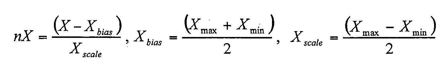
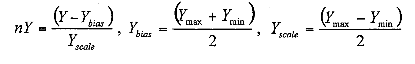
- the control unit 140 carries out the normalization by substituting parameters of the formula below with the maximum and the minimum values recorded on the memory 150 and the X and Y axis output values detected from the signal detection unit 130.
- nX X - X bias X scale
- X bias X max + X min 2
- X scale X max - X min 2
- nY Y - Y bias Y scale
- Y bias Y max + Y min 2
- Y scale Y max - Y min 2
- X and Y indicate the output values of the X and Y axis fluxgates 121 and 123, respectively
- nX and nY indicate the normalization values of the X and Y axes, respectively
- Xmax and Xmin indicate the maximum and the minimum values of the X axis, respectively
- Ymax and Ymin indicate the maximum and the minimum values of the Y axis, respectively.
- the control unit 140 uses the Xmax, Xmin, Ymax, and Ymin for the formula 1 which were measured and recorded in the memory 150, and calculates the Xbias, Xscale, Ybias, and Yscale, and uses the resultant values to calculate nX and nY.
- control unit 140 determines whether the normalized output value of each of the X and Y axes is distorted. As a result, the control unit 140 controls the display unit 160 to inform the user that the azimuth information being calculated and output might have an error upon determination that it is distorted.
- the display unit 160 may inform the user of the fact by means of a certain Liquid Crystal Display (LCD) screen, a Light Emitting Diode (LED) or the like.
- the procedure for the control unit 140 to determine whether the normalized output value of each axis is distorted is as follows.
- the control unit 140 has each of the normalized X axis output value (hereinafter, it will be referred to as an nX) and the normalized Y axis output value (hereinafter, it will be referred to as an nY) squared and added together, and determines whether the added value is in a predetermined tolerable range. It determines that the normal azimuth information is calculated when the resultant value is within the tolerable range, and determines that each output value of the axes is distorted when the resultant value is outside of the tolerable range.
- the X and Y axis output values of the geomagnetic sensor 100 represent the cosine waveform 201 and the sine waveform 202 as shown in FIG. 3A, respectively. Referring to FIG. 3A, it can be seen that each of the axis output values is normalized in a range of ⁇ 1.
- FIG. 3B is a graph showing the correlation between the X-axis and the Y-axis output values which are normalized in a range of ⁇ 1.
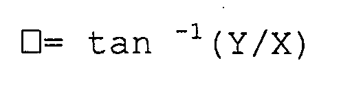
- the X and Y axis output values are represented as the cosine function value and the sine function value, respectively, so that the correlation may be expressed as the following formula 2.
- nX and nY indicate the normalized X and Y axis output values, respectively, ⁇ is a calculated value, and ⁇ is an azimuth angle.
- the user may use the geomagnetic sensor 100 in various places, so that the azimuth angle may be detected in an inclined state or in an environment other than the magnetic field environment in which the user has carried out the compensation procedure of the geomagnetic sensor 100.
- the X and Y axis output values are distorted due to the circumferential magnetic field or the inclination, so that the unit circle (which is a circle having a radius of "1") as shown in FIG. 3B is not obtained.
- the resultant value ⁇ does not become 1.
- FIG. 4A and 4B are graphs showing respectively the correlation of the X and Y axis output values when ⁇ is not 1.
- FIG. 4A shows the graph that the X and Y axis output values are measured in a horizontal state but in the magnetic field environment other than the environment in which the compensation is carried out.
- the graph 20 shows the relation of the X and Y axis output values in the environment in which the compensation is carried out, wherein each output value of the X and Y axes is normalized in a range of ⁇ 1 so that the sum of the respective squared output values becomes 1, which in turn shows the unit circle.
- each of the relationship graphs 20a and 20b represents a circles having a radius other than 1 in each state.
- A(nX, nY) is detected according to the relationship graph 20 in the same magnetic field environment as the environment in which the compensation is carried out, however, B(nX', nY') is detected due to each reduced amplitude of the output values of the X and Y axes in an area having a weak geomagnetism, and C(nX", nY") is detected due to each increased amplitude of the output values of the X and Y axes in an area having a circumferentially strong geomagnetism.
- FIG. 4B corresponds to the same magnetic field environment, however, this figure shows the relationship graph of each output value of the X and Y axes detected while the geomagnetic sensor 100 is inclined.
- the relationship graph in the compensation environment shows the unit circle 30a, however, it shows an elliptical shape 30b when the geomagnetic sensor is inclined.
- each output value of the X and Y axes is distorted to be detected except the specific areas d1 and d2 where the unit circle 30a and the elliptical shape 30b are overlapped with each other.
- a correct azimuth angle may be detected when it is measured by chance in these areas d1 and d2, however, it is reasonable that the azimuth angle information generally has an error.
- ⁇ becomes 1 in the environment in which the compensation is carried out, however, it is detected as a value other than 1 when the geomagnetic field environment changes or the inclination occurs.
- an additional separate sensor such as an acceleration sensor, gyro sensor or the like is employed to recognize the inclined position, and the control unit 140 may control the display unit 160 for displaying that the azimuth angle information to be output may have an error.
- control unit 140 recognizes that the current output values of the X and Y axes are distorted when the calculated value ⁇ is not 1. As a result, it determines that the azimuth angle information to be finally calculated may have an error. The control unit 140 may determine that the final azimuth angle is generally correct when it is within a tolerable range although ⁇ is not exactly 1.
- the manufacturer of the geomagnetic sensor 100 may check the constant range of ⁇ in which the tolerable azimuth angle information is obtained through a pre-test. Accordingly, the range of ⁇ . is set as the tolerable range so that it may be stored in the memory 150. As a result, when the control unit 140 determines that the calculated value after each output value of the X and Y axes actually detected is squared and added together is within the tolerable range, it may determine that a correct azimuth angle is generally detected.
- the control unit determines that the azimuth angle information has no error.
- the control unit 140 controls the display unit 160 for displaying that the azimuth angle information to be output may have an error. Accordingly, the user may calculate a new scale factor and a new bias factor after he/she carries out a new compensation procedure to measure the maximum value and the minimum value of each output value of the X and Y axes.
- FIG. 5 is a flow chart for explaining a method for measuring the azimuth angle of a geomagnetic sensor in accordance with an exemplary embodiment of the present invention.
- the driving signal generation unit 110 applies a driving signal to the geomagnetism detection module 120, and the resultantly detected electrical signals pass through the signal processing unit 130 so that they are detected as predetermined output values of the X and Y axes (step S510).
- the control unit 140 applies the detected output values of the X and Y axes to the formula 1 and carries out the normalization, and uses the formula 2 to calculate ⁇ (step S520).
- the control unit 140 may control the display unit 160 for displaying the warning message that the azimuth angle information to be displayed may have an error (step S550).
- the control unit may have even the azimuth angle information which has a possibility of including an error displayed (step 540). Accordingly, the user may use the azimuth angle as it is if for example when he/she determines that the error is not significant.
- the user when the user recognizes the warning message, he/she preferably carries out the compensation procedure by newly rotating the geomagnetic sensor 100 one time at the current position to detect the correct azimuth angle information having no error.
- the two axis fluxgates may be simply employed to determine whether there might be an error, so that there are no hardware limitations.
- warning mechanisms may be employed, such as an audible warning and/or a vibrating warning signal.
- a simple warning light may be displayed to the user.
Landscapes
- Engineering & Computer Science (AREA)
- Remote Sensing (AREA)
- Radar, Positioning & Navigation (AREA)
- Physics & Mathematics (AREA)
- General Physics & Mathematics (AREA)
- General Engineering & Computer Science (AREA)
- Mechanical Engineering (AREA)
- Life Sciences & Earth Sciences (AREA)
- Environmental & Geological Engineering (AREA)
- General Life Sciences & Earth Sciences (AREA)
- Geology (AREA)
- Electromagnetism (AREA)
- Measuring Magnetic Variables (AREA)
Claims (13)
- Erdmagnetsensor, umfassend:ein Erdmagnetismus-Erfassungsmodul (120), das ein X-Achsen-Fluxgate (121) und ein Y-Achsen-Fluxgate (123) aufweist und so angeordnet ist, dass es einen Erdmagnetismus von jedem des X-Achsen- und des Y-Achsen-Fluxgates erfasst;eine Signalverarbeitungseinheit (130) zum Umwandeln von Signalausgängen von dem Erdmagnetismus-Erfassungsmodul in X-Achsen- und Y-Achsen-Ausgabewerte; undeine Steuereinheit (140) zum Feststellen, ob die Ausgabewerte der X- und der Y-Achse verzerrt sind, und zum Bereitstellen einer Warnmeldung nach der Feststellung, dass wenigstens einer der Ausgabewerte verzerrt ist,und dadurch charakterisiert, dass:das X-Achsen-Fluxgate (121) einen ersten Magnetkern umfasst, und das Y-Achsen-Fluxgate (123) einen zweiten Magnetkern umfasst; unddas Erdmagnetismus-Erfassungsmodul so ausgelegt ist, dass es einen Erdmagnetismus des X-Achsen-Fluxgates (121) erfasst, wenn das X-Achsen-Fluxgate (121) durch ein erstes Signal angetrieben wird, und dass es einen Erdmagnetismus des Y-Achsen-Fluxgates (123) erfasst, wenn das Y-Achsen-Fluxgate (123) durch ein zweites Signal angetrieben wird.
- Erdmagnetsensor nach Anspruch 1, wobei die Steuereinheit (140) die Ausgabewerte der X- und der Y-Achse zu Werten in einem vorgegebenen tolerierbaren Bereich normalisiert und feststellt, dass wenigstens einer der Ausgabewerte der X- und der Y-Achse verzerrt ist, wenn jeder der normalisierten Ausgabewerte, der zum Quadrat erhoben und addiert ist, außerhalb des vorgegebenen tolerierbaren Bereichs liegt.
- Erdmagnetsensor nach -Anspruch 2, wobei die Steuereinheit (140) die Ausgabewerte der X- und der Y-Achse unter Verwendung der folgenden Formeln normalisiert:
wobei X und Y jeweils die Ausgabewerte der X- und der Y-Achse angeben, nX und nY jeweils die Normalisierungswerte der X- und der Y-Achse angeben, Xmax und Xmin jeweils den maximalen und den minimalen Wert der X-Achse angeben, und Ymax und Ymin jeweils den maximalen und den minimalen Wert der Y-Achse angeben. - Erdmagnetsensor nach Anspruch 2 oder 3, wobei die Steuereinheit (140) die normalisierten Ausgabewerte der X- und der Y-Achse auf die folgende Formel anwendet, um einen Azimutwinkel □zu berechnen:

wobei X und Y jeweils normalisierte Ausgabewerte der X- und der Y-Achse sind und □ein Azimutwinkel ist. - Erdmagnetsensor nach einem beliebigen vorhergehenden Anspruch, des Weiteren umfassend einen Speicher (150) zum Speichern von Informationen über einen maximalen Ausgabewert und einen minimalen Ausgabewert für jedes des X- und des Y-Achsen-Fluxgates.
- Erdmagnetsensor nach einem beliebigen vorhergehenden Anspruch, wobei das X-Achsen- und das Y-Achsen-Fluxgate zueinander orthogonal sind.
- Erdmagnetsensor nach einem beliebigen vorhergehenden Anspruch, des Weiteren umfassend eine Anzeigeeinheit (160), und wobei die Steuereinheit (140) betriebsfähig ist, die Anzeigeeinheit (160) so zu steuern, dass sie eine vorgegebene Warnmeldung ausgibt nach der Feststellung, dass wenigstens einer der Ausgabewerte verzerrt ist.
- Verfahren zum Messen eines Azimutwinkels eines Erdmagnetsensors, der ein X-Achsen-Fluxgate(121) mit einem ersten Magnetkern und ein Y-Achsen-Fluxgate (123) mit einem zweiten Magnetkern aufweist, umfassend:(a) Erfassen von Ausgabewerten der X- und der Y-Achse, die einem Erdmagnetismus von dem X- und dem Y-Achsen-Fluxgate entsprechen;(b) Feststellen, ob die Ausgabewerte der Y- und der Y-Achse verzerrt sind; und(c) Bereitstellen einer Warnmeldung nach der Feststellung, das wenigstens einer der Ausgabewerte der X- und der Y-Achse verzerrt ist,und wobei der Schritt (a) des Erfassens der X- und Y-Achsen-Ausgabewerte folgende Schritte umfasst:(a1) Erfassen von X-Achsen-Ausgabewerten, die einem Erdmagnetismus von dem X-Achsen-Fluxgate (121) entsprechen, wenn das X-Achsen-Fluxgate durch ein erstes Signal angetrieben wird; und(a2) Erfassen von Y-Achsen-Ausgabewerten, die einem Erdmagnetismus von dem Y-Achsen-Fluxgate (123) entsprechen, wenn das Y-Achsen-Fluxgate durch ein zweites Signal angetrieben wird.
- Verfahren nach Anspruch 8, des Weiteren umfassend das Normalisieren der Ausgabewerte der X- und der Y-Achse zu Werten in einem vorgegebenen Bereich mittels der folgenden Formeln:


wobei X und Y jeweils die Ausgabewerte der X- und der Y-Achse angeben, nX und nY jeweils die Normalisierungswerte der X- und der Y-Achse angeben, Xmax und Xmin jeweils den maximalen und den minimalen Wert der X-Achse angeben, und Ymax und Ymin jeweils den maximalen und den minimalen Wert der Y-Achse angeben. - Verfahren nach Anspruch 9, wobei der Schritt (b) des Feststellens umfasst:Erheben jedes der normalisierten Ausgabewerte der X- und der Y-Achse zum Quadrat und ihr Addieren, um einen daraus resultierenden Wert zu erfassen;Feststellen, ob der daraus resultierende Wert in einem vorgegebenen tolerierbaren Bereich liegt; undFeststellen, dass wenigstens einer der Ausgabewerte der X- und der Y-Achse verzerrt ist, wenn der daraus resultierende Wert außerhalb des vorgegebenen tolerierbaren Bereichs liegt.
- Verfahren nach Anspruch 10, des Weiteren umfassend:Anwenden der normalisierten Ausgabewerte der X- und der Y-Achse auf die folgende Formel, um einen Azimutwinkel □zu berechnen:
 wobei X und Y jeweils normalisierte Ausgabewerte der X- und der Y-Achse sind und □ein Azimutwinkel ist.
 - Verfahren nach einem irgendeinem der Ansprüche 8 bis 11, wobei das X-Achsen-Fluxgate orthogonal zu dem Y-Achsen-Fluxgate ist.
- Verfahren nach irgendeinem der Ansprüche 8 bis 12, wobei das Warnsignal nach der Feststellung angezeigt wird, dass wenigstens einer der Ausgabewerte der X- und der Y-Achse verzerrt ist.
Applications Claiming Priority (2)
| Application Number | Priority Date | Filing Date | Title |
|---|---|---|---|
| KR1020040013068A KR100574506B1 (ko) | 2004-02-26 | 2004-02-26 | 연산된 방위각의 오류여부를 표시하는 지자기센서 및 그방위각측정방법 |
| KR2004013068 | 2004-02-26 |
Publications (2)
| Publication Number | Publication Date |
|---|---|
| EP1568967A1 EP1568967A1 (de) | 2005-08-31 |
| EP1568967B1 true EP1568967B1 (de) | 2008-01-02 |
Family
ID=34747954
Family Applications (1)
| Application Number | Title | Priority Date | Filing Date |
|---|---|---|---|
| EP05251105A Expired - Lifetime EP1568967B1 (de) | 2004-02-26 | 2005-02-24 | Geomagnetischer Sensor und Verfahren zur Anzeige einer Störung des erfassten Azimutwinkels |
Country Status (5)
| Country | Link |
|---|---|
| US (1) | US7168176B2 (de) |
| EP (1) | EP1568967B1 (de) |
| JP (1) | JP2005241650A (de) |
| KR (1) | KR100574506B1 (de) |
| DE (1) | DE602005004046T2 (de) |
Families Citing this family (17)
| Publication number | Priority date | Publication date | Assignee | Title |
|---|---|---|---|---|
| KR100555656B1 (ko) * | 2003-08-27 | 2006-03-03 | 삼성전자주식회사 | 복각 검출 기능을 지원하는 지자기 센서 및 그 검출 방법 |
| KR100594971B1 (ko) * | 2004-01-09 | 2006-06-30 | 삼성전자주식회사 | 지자기 센서를 이용한 입력장치 및 이를 이용한 입력신호생성방법 |
| US7707050B2 (en) * | 2004-03-11 | 2010-04-27 | Risk Management Solutions, Inc. | Systems and methods for determining concentrations of exposure |
| US7523559B2 (en) * | 2004-04-07 | 2009-04-28 | Continental Automotive Systems Us, Inc. | Compass heading noise immunity |
| KR100620957B1 (ko) * | 2004-12-13 | 2006-09-19 | 삼성전기주식회사 | 방위각을 측정하는 지자기센서 및 그 방법 |
| JP2008089517A (ja) * | 2006-10-04 | 2008-04-17 | Sony Corp | 方位判別装置、方位判別方法及び方位判別プログラム |
| US20080284583A1 (en) * | 2007-05-17 | 2008-11-20 | Yung-Fa Lin | Electronic Compass |
| US8464433B1 (en) * | 2009-07-07 | 2013-06-18 | Milli Sensor Systems & Actuators, Inc. | Human-portable MEMS Azimuth sensing unit and method |
| KR101706616B1 (ko) * | 2009-11-09 | 2017-02-14 | 삼성전자주식회사 | 로드 임피던스 결정 장치, 무선 전력 전송 장치 및 그 방법 |
| EP2621809A4 (de) * | 2010-10-01 | 2017-12-06 | Hillcrest Laboratories, Inc. | Vorrichtungen und verfahren zur bestimmung des gierwinkels einer vorrichtung in einem gravitations-referenzsystem durch messung von bewegungssensoren und mithilfe eines an der vorrichtung befestigten magnetometers |
| CN103299247B (zh) * | 2010-11-17 | 2016-03-16 | 希尔克瑞斯特实验室公司 | 用于磁近场的动态追踪及补偿的设备和方法 |
| US10325005B2 (en) | 2010-11-17 | 2019-06-18 | Idhl Holdings, Inc. | Apparatuses and methods for calibrating magnetometer attitude-independent parameters |
| US9719782B2 (en) * | 2014-10-20 | 2017-08-01 | Honeywell International Inc. | Method of detecting attitude faults based on magnetometer measurements |
| CN104596510A (zh) * | 2014-12-23 | 2015-05-06 | 深圳市金立通信设备有限公司 | 一种终端 |
| EP3115738B1 (de) * | 2015-07-06 | 2020-09-02 | Safran Vectronix AG | Optoelektronisches messgerät und verfahren zur störungserkennung |
| CN112378393B (zh) * | 2020-09-24 | 2022-06-03 | 杭州瑞利超声科技有限公司 | 一种漂浮式抗倾斜方位磁通门探头检测装置 |
| WO2023049693A2 (en) | 2021-09-24 | 2023-03-30 | Johnson & Johnson Consumer Inc. | Dosage forms for the delivery of a probiotic |
Family Cites Families (20)
| Publication number | Priority date | Publication date | Assignee | Title |
|---|---|---|---|---|
| US4672565A (en) * | 1981-03-10 | 1987-06-09 | Nippon Soken, Inc. | Direction detecting system for vehicles |
| US4797841A (en) * | 1983-11-28 | 1989-01-10 | Magnavox Government And Industrial Electronics Company | Method and apparatus for automatic calibration of magnetic compass |
| US4611293A (en) * | 1983-11-28 | 1986-09-09 | Magnavox Government And Industrial Electronics Company | Method and apparatus for automatic calibration of magnetic compass |
| US4668100A (en) * | 1985-09-03 | 1987-05-26 | Citizen Watch Co., Ltd. | Electronic equipment with geomagnetic direction sensor |
| US4698912A (en) * | 1985-12-11 | 1987-10-13 | The Laitram Corporation | Magnetic compass calibration |
| US5170566A (en) * | 1990-06-05 | 1992-12-15 | Arthur D. Little, Inc. | Means for reducing interference among magnetometer array elements |
| US5239264A (en) * | 1991-11-14 | 1993-08-24 | Precision Navigation, Inc. | Zero-offset magnetometer having coil and core sensor controlling period of an oscillator circuit |
| US5644851A (en) * | 1991-12-20 | 1997-07-08 | Blank; Rodney K. | Compensation system for electronic compass |
| JPH06249663A (ja) * | 1993-02-23 | 1994-09-09 | Mitsubishi Electric Corp | 方位検出装置 |
| JPH09325029A (ja) | 1996-06-05 | 1997-12-16 | Fuji Heavy Ind Ltd | 地磁気センサの補正装置 |
| US6130534A (en) * | 1998-03-10 | 2000-10-10 | Chung Shan Institute Of Science And Technology | Method of calibrating a three-axis magnetometer |
| US6282803B1 (en) * | 1998-04-24 | 2001-09-04 | Laser Technology, Inc. | Self calibration circuit for determining an accurate zero compensation for a fluxgate compass |
| JP4026937B2 (ja) * | 1998-06-29 | 2007-12-26 | 古野電気株式会社 | 電子磁気コンパス |
| JP4034039B2 (ja) | 2000-10-16 | 2008-01-16 | 電通企工株式会社 | 携帯電話 |
| US6543146B2 (en) | 2000-12-06 | 2003-04-08 | Honeywell International, Inc. | Electronic compass and compensation of large magnetic errors for operation over all orientations |
| US6539639B2 (en) | 2000-12-06 | 2003-04-01 | Honeywell International Inc. | Monitoring accuracy of an electronic compass |
| EP1336858A3 (de) * | 2002-02-19 | 2005-03-23 | Aichi Micro Intelligent Corporation | Zweidimensionaler Magnetfeldsensor |
| KR100571795B1 (ko) * | 2004-02-06 | 2006-04-18 | 삼성전자주식회사 | 복각 검출 기능을 지원하는 지자기 센서 및 그 방법 |
| US6964107B1 (en) * | 2004-05-27 | 2005-11-15 | Nokia Corporation | System, method, device and computer code product for improving the readability of an electronic compass |
| JP2006234581A (ja) * | 2005-02-24 | 2006-09-07 | Aichi Micro Intelligent Corp | 電子コンパス及び方位測定方法 |
-
2004
- 2004-02-26 KR KR1020040013068A patent/KR100574506B1/ko not_active Expired - Fee Related
-
2005
- 2005-02-24 EP EP05251105A patent/EP1568967B1/de not_active Expired - Lifetime
- 2005-02-24 DE DE602005004046T patent/DE602005004046T2/de not_active Expired - Fee Related
- 2005-02-25 JP JP2005051636A patent/JP2005241650A/ja active Pending
- 2005-02-28 US US11/067,208 patent/US7168176B2/en not_active Expired - Fee Related
Also Published As
| Publication number | Publication date |
|---|---|
| DE602005004046D1 (de) | 2008-02-14 |
| JP2005241650A (ja) | 2005-09-08 |
| DE602005004046T2 (de) | 2008-08-28 |
| US20050188556A1 (en) | 2005-09-01 |
| KR100574506B1 (ko) | 2006-04-27 |
| EP1568967A1 (de) | 2005-08-31 |
| US7168176B2 (en) | 2007-01-30 |
| KR20050087323A (ko) | 2005-08-31 |
Similar Documents
| Publication | Publication Date | Title |
|---|---|---|
| EP1568967B1 (de) | Geomagnetischer Sensor und Verfahren zur Anzeige einer Störung des erfassten Azimutwinkels | |
| US7486323B2 (en) | Portable electronic device for changing menu display state according to rotating degree and method thereof | |
| US7755353B2 (en) | Three-axis fluxgate-type magnetism detecting device | |
| JP2007248477A (ja) | 勾配の影響を補償し方位角を演算する地磁気センサー、およびその演算方法 | |
| KR100571795B1 (ko) | 복각 검출 기능을 지원하는 지자기 센서 및 그 방법 | |
| JP3934633B2 (ja) | 伏角検出機能を支援する地磁気センサー及びその検出方法 | |
| CN1989392B (zh) | 用于提高电子罗盘可读性的系统、方法、设备 | |
| EP1790941A2 (de) | Geomagnetischer Sensor zur Azimutberechnung und Verfahren dafür | |
| US6640454B2 (en) | Electronic instrument having a magnetic sensor | |
| JP2006170997A (ja) | 方位角を測定する地磁気センサ及びその方法 | |
| EP1626249A2 (de) | Geomagnetischer Sensor für Selbstkalibrierung von Magnetfeldabweichung und Verfahren zur Verwendung davon. | |
| KR100655936B1 (ko) | 방위각 측정 장치 및 방법 | |
| JP2000321067A (ja) | 電子方位計及び電子方位計付時計 | |
| KR19990014652A (ko) | 선박의 방위 측정장치 및 그 방법 |
Legal Events
| Date | Code | Title | Description |
|---|---|---|---|
| PUAI | Public reference made under article 153(3) epc to a published international application that has entered the european phase |
Free format text: ORIGINAL CODE: 0009012 |
|
| AK | Designated contracting states |
Kind code of ref document: A1 Designated state(s): AT BE BG CH CY CZ DE DK EE ES FI FR GB GR HU IE IS IT LI LT LU MC NL PL PT RO SE SI SK TR |
|
| AX | Request for extension of the european patent |
Extension state: AL BA HR LV MK YU |
|
| 17P | Request for examination filed |
Effective date: 20051005 |
|
| AKX | Designation fees paid |
Designated state(s): DE FR GB SE |
|
| 17Q | First examination report despatched |
Effective date: 20060920 |
|
| GRAP | Despatch of communication of intention to grant a patent |
Free format text: ORIGINAL CODE: EPIDOSNIGR1 |
|
| GRAS | Grant fee paid |
Free format text: ORIGINAL CODE: EPIDOSNIGR3 |
|
| GRAA | (expected) grant |
Free format text: ORIGINAL CODE: 0009210 |
|
| AK | Designated contracting states |
Kind code of ref document: B1 Designated state(s): DE FR GB SE |
|
| REG | Reference to a national code |
Ref country code: GB Ref legal event code: FG4D |
|
| REF | Corresponds to: |
Ref document number: 602005004046 Country of ref document: DE Date of ref document: 20080214 Kind code of ref document: P |
|
| ET | Fr: translation filed | ||
| PG25 | Lapsed in a contracting state [announced via postgrant information from national office to epo] |
Ref country code: SE Free format text: LAPSE BECAUSE OF FAILURE TO SUBMIT A TRANSLATION OF THE DESCRIPTION OR TO PAY THE FEE WITHIN THE PRESCRIBED TIME-LIMIT Effective date: 20080402 |
|
| PLBE | No opposition filed within time limit |
Free format text: ORIGINAL CODE: 0009261 |
|
| STAA | Information on the status of an ep patent application or granted ep patent |
Free format text: STATUS: NO OPPOSITION FILED WITHIN TIME LIMIT |
|
| 26N | No opposition filed |
Effective date: 20081003 |
|
| PGFP | Annual fee paid to national office [announced via postgrant information from national office to epo] |
Ref country code: DE Payment date: 20090123 Year of fee payment: 5 |
|
| PGFP | Annual fee paid to national office [announced via postgrant information from national office to epo] |
Ref country code: GB Payment date: 20090217 Year of fee payment: 5 |
|
| PGFP | Annual fee paid to national office [announced via postgrant information from national office to epo] |
Ref country code: FR Payment date: 20090213 Year of fee payment: 5 |
|
| GBPC | Gb: european patent ceased through non-payment of renewal fee |
Effective date: 20100224 |
|
| REG | Reference to a national code |
Ref country code: FR Ref legal event code: ST Effective date: 20101029 |
|
| PG25 | Lapsed in a contracting state [announced via postgrant information from national office to epo] |
Ref country code: FR Free format text: LAPSE BECAUSE OF NON-PAYMENT OF DUE FEES Effective date: 20100301 |
|
| PG25 | Lapsed in a contracting state [announced via postgrant information from national office to epo] |
Ref country code: DE Free format text: LAPSE BECAUSE OF NON-PAYMENT OF DUE FEES Effective date: 20100901 |
|
| PG25 | Lapsed in a contracting state [announced via postgrant information from national office to epo] |
Ref country code: GB Free format text: LAPSE BECAUSE OF NON-PAYMENT OF DUE FEES Effective date: 20100224 |