EP1568923A1 - Druckentlastungsventil - Google Patents
Druckentlastungsventil Download PDFInfo
- Publication number
- EP1568923A1 EP1568923A1 EP05101345A EP05101345A EP1568923A1 EP 1568923 A1 EP1568923 A1 EP 1568923A1 EP 05101345 A EP05101345 A EP 05101345A EP 05101345 A EP05101345 A EP 05101345A EP 1568923 A1 EP1568923 A1 EP 1568923A1
- Authority
- EP
- European Patent Office
- Prior art keywords
- valve assembly
- assembly according
- valve body
- piston
- seat
- Prior art date
- Legal status (The legal status is an assumption and is not a legal conclusion. Google has not performed a legal analysis and makes no representation as to the accuracy of the status listed.)
- Withdrawn
Links
- 238000007789 sealing Methods 0.000 claims abstract description 29
- 239000012530 fluid Substances 0.000 claims abstract description 27
- 230000006835 compression Effects 0.000 claims abstract description 10
- 238000007906 compression Methods 0.000 claims abstract description 10
- 230000000670 limiting effect Effects 0.000 claims description 9
- 230000008878 coupling Effects 0.000 claims description 8
- 238000010168 coupling process Methods 0.000 claims description 8
- 238000005859 coupling reaction Methods 0.000 claims description 8
- 239000003921 oil Substances 0.000 description 10
- 230000009471 action Effects 0.000 description 3
- 230000007423 decrease Effects 0.000 description 2
- 238000012856 packing Methods 0.000 description 2
- 230000000712 assembly Effects 0.000 description 1
- 238000000429 assembly Methods 0.000 description 1
- 239000010720 hydraulic oil Substances 0.000 description 1
- 238000009434 installation Methods 0.000 description 1
- 238000012423 maintenance Methods 0.000 description 1
- 239000000463 material Substances 0.000 description 1
- 238000000034 method Methods 0.000 description 1
- 238000012986 modification Methods 0.000 description 1
- 230000004048 modification Effects 0.000 description 1
- 238000011017 operating method Methods 0.000 description 1
- 230000009467 reduction Effects 0.000 description 1
- 238000000926 separation method Methods 0.000 description 1
Images

Classifications
-
- F—MECHANICAL ENGINEERING; LIGHTING; HEATING; WEAPONS; BLASTING
- F16—ENGINEERING ELEMENTS AND UNITS; GENERAL MEASURES FOR PRODUCING AND MAINTAINING EFFECTIVE FUNCTIONING OF MACHINES OR INSTALLATIONS; THERMAL INSULATION IN GENERAL
- F16K—VALVES; TAPS; COCKS; ACTUATING-FLOATS; DEVICES FOR VENTING OR AERATING
- F16K17/00—Safety valves; Equalising valves, e.g. pressure relief valves
- F16K17/02—Safety valves; Equalising valves, e.g. pressure relief valves opening on surplus pressure on one side; closing on insufficient pressure on one side
- F16K17/04—Safety valves; Equalising valves, e.g. pressure relief valves opening on surplus pressure on one side; closing on insufficient pressure on one side spring-loaded
- F16K17/06—Safety valves; Equalising valves, e.g. pressure relief valves opening on surplus pressure on one side; closing on insufficient pressure on one side spring-loaded with special arrangements for adjusting the opening pressure
-
- F—MECHANICAL ENGINEERING; LIGHTING; HEATING; WEAPONS; BLASTING
- F16—ENGINEERING ELEMENTS AND UNITS; GENERAL MEASURES FOR PRODUCING AND MAINTAINING EFFECTIVE FUNCTIONING OF MACHINES OR INSTALLATIONS; THERMAL INSULATION IN GENERAL
- F16K—VALVES; TAPS; COCKS; ACTUATING-FLOATS; DEVICES FOR VENTING OR AERATING
- F16K17/00—Safety valves; Equalising valves, e.g. pressure relief valves
- F16K17/02—Safety valves; Equalising valves, e.g. pressure relief valves opening on surplus pressure on one side; closing on insufficient pressure on one side
- F16K17/04—Safety valves; Equalising valves, e.g. pressure relief valves opening on surplus pressure on one side; closing on insufficient pressure on one side spring-loaded
- F16K17/10—Safety valves; Equalising valves, e.g. pressure relief valves opening on surplus pressure on one side; closing on insufficient pressure on one side spring-loaded with auxiliary valve for fluid operation of the main valve
-
- F—MECHANICAL ENGINEERING; LIGHTING; HEATING; WEAPONS; BLASTING
- F16—ENGINEERING ELEMENTS AND UNITS; GENERAL MEASURES FOR PRODUCING AND MAINTAINING EFFECTIVE FUNCTIONING OF MACHINES OR INSTALLATIONS; THERMAL INSULATION IN GENERAL
- F16K—VALVES; TAPS; COCKS; ACTUATING-FLOATS; DEVICES FOR VENTING OR AERATING
- F16K17/00—Safety valves; Equalising valves, e.g. pressure relief valves
- F16K17/18—Safety valves; Equalising valves, e.g. pressure relief valves opening on surplus pressure on either side
Definitions
- the present invention relates to a pressure relief valve assembly.
- pressure relief valves are used in circuits in which there is a pressurized fluid and are sized so as to allow to discharge the fluid when the working pressure inside the circuit exceeds a safety threshold value for which such valves are calibrated.
- cartridge valves which are provided as a preassembled subassembly, which during installation must be fitted in an appropriately provided seat connected to the circuit to be protected and to a discharge duct.
- these valves comprise an internally hollow and substantially elongated valve body, which can be accommodated in the seat by arranging it so that a first end is inserted inside the seat and a second end, arranged opposite the first end, protrudes externally or in any case can be accessed from the outside.
- the valve body is provided with a longitudinal through hole, which forms the intake port for the fluid at the working pressure at said first end.
- valve body Proximate to the intake port, the valve body is provided with a lateral opening that provides the discharge port for said fluid.
- spring guiding piston which is associated with the spring on the opposite side of the flow control element and is accommodated so that it can slide along the longitudinal hole of the valve body; the axial position of the piston along the hole can be adjusted by way of screw means, which are formed monolithically with respect to the piston or are associated with the valve body at the second end and can be accessed by an assigned operator, the longitudinal hole being threaded internally at the second end for coupling to said screw means.
- pressure relief valve of the so-called direct-action type
- more complex embodiments such as pilot-operated valves, which are provided with two flow control elements: a main flow control element at the intake port, which opens by way of the action of a difference in pressure between the inside and the outside of the valve body, and a pilot flow control element, which is arranged inside the valve body and whose opening is normally contrasted by an elastic compression spring, the preloading of which can be adjusted by the user by way of screw means.
- pressure relief valves can be sized so as to perform, in addition to the conventional safety function, an emptying-check function.
- the areas exposed to the working and discharge pressures are sized so as to open the flow control elements if the latter is higher than the former, so as to allow the reverse flow of the fluid inside the circuit and prevent its emptying.
- the adjustment of the tripping pressure of the valve cannot be performed while "hot”, i.e., while fluid at high pressure and temperature is present in the circuit in which the valve is inserted, since leaks of fluid may occur which, in addition to being potentially harmful for the assigned operators, may damage the adjacent equipment and dirty and possibly contaminate the surrounding environment.
- the aim of the present invention is to eliminate the above-mentioned drawbacks of known valves, by providing a pressure relief valve assembly that allows to adjust the threshold pressure for which said assembly discharges the circuit to which it is applied both at the bench and while the circuit is operating, in optimum safety conditions for the assigned operators and without the risk of damaging the environment in which it is fitted.
- an object of the present invention is to avoid leaks of fluid in any operating condition.
- Another object of the present invention is to maintain the correct functionality of the valve assembly during adjustment of the threshold pressure, avoiding the packing of the spring and the consequent jamming of the flow control element.
- Another object of the present invention is to provide a pressure relief valve that is simple, relatively easy to provide in practice, safe in use, effective in operation, and has a relatively low cost.
- the present pressure relief valve assembly which comprises a valve body that has a substantially elongated shape, is internally hollow and open at its ends, and can be associated hermetically in a corresponding receptacle, which is associated with a working circuit of a fluid at a working pressure and with a discharge duct for said fluid at a discharge pressure, with a first end inserted therein and with a second end, arranged opposite the first end, that can be accessed from the outside; a fluid intake port, which is associated with said first end and is suitable to be connected to the working circuit; at least one fluid discharge port, which is associated with said valve body and is suitable to be connected to the discharge duct; at least one seat for the abutment of a corresponding flow control element, which is accommodated so that it can slide within said valve body and is suitable to be exposed, by means of said intake port, to the fluid at the working pressure; elastic compression means, which are accommodated within said valve body in order to keep said
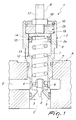
- the reference numeral 1 generally designates a pressure relief valve assembly.
- the valve assembly 1 is preferably of the type that is conventionally known as cartridge valve.
- the valve assembly 1 comprises a valve body 2, which has an elongated shape, is internally hollow and open at its ends, and is accommodated, during use, in a corresponding receptacle A, which is shown schematically in the figures and is associated with a working circuit C of a fluid, such as hydraulic oil, at a working pressure and with a discharge duct S for said fluid at a discharge pressure, which is normally lower than the working pressure, with one first end inserted within said receptacle and a second end that protrudes from said receptacle or in any case can be accessed from the outside.
- a fluid such as hydraulic oil
- valve body 2 is screwed into the receptacle A by interposing rubber sealing rings T, which avoid seepage of oil between the valve assembly 1 and said receptacle.
- valve assembly 1 in the receptacle A
- alternative methods for fitting the valve assembly 1 in the receptacle A such as for example fixing by means of threaded elements that are engaged in a flange that is rigidly coupled to the valve body 2.
- valve assembly 1 comprises an oil intake port 3, which is associated with the valve body 2 at its first end and is suitable to be connected to the circuit C, and at least one oil discharge port 4, which is associated with the valve body 2 and is suitable to be connected to the discharge duct S.
- elastic compression means are accommodated within the valve body 2 and are constituted by a helical spring 7 for keeping the flow control element 6 in abutment against the seat 5; one end of the spring is associated with the flow control element and the opposite end is associated with a piston 8, which is slidingly accommodated within the valve body 2.
- means 9 for adjusting the position of the piston 8 along the valve body 2 are provided and are associated therewith at its second end.
- the valve body 2 comprises at least one first portion 2a and one second portion 2b, which are perforated and mutually associated so that their respective holes are connected.
- the second portion 2b is arranged at the second end of the valve body 2 and is associated with the adjustment means 9, and its corresponding hole has a transverse cross-section that is substantially smaller than the cross-section of the piston 8, at least in a portion that is interposed between the piston and the second end of the valve body 2.
- sealing means 10 are provided which are associated with the valve body 2 so as to prevent the escape of pressurized oil from the second end; the sealing means 10 can be interposed between the piston 8 and the valve body 2 or between the second portion 2b and the adjustment means 9.
- the sealing means 10 and the optional additional sealing means 11 comprise respective sealing rings or the like.
- valve assembly 1 is provided with means 12 for limiting the sliding of the piston 8 along the valve body 2 toward the seat 5.
- valve assembly 1 is of the direct-action type.
- the seat 5 is formed in the first portion 2a and substantially coincides with the intake port 3; the discharge port 4 is formed by a transverse opening, which is formed in the first portion 2a on the opposite side with respect to the intake port 3 relative to the seat 5.
- the limiting means 12 are constituted by a shoulder 13 for the abutment of the piston 8, which protrudes internally from the first portion 2a and is arranged at a distance from the seat 5 that is sized so as to avoid the packing of the spring 7.
- the sealing means 10 are constituted by a conventional sealing ring 14 made of rubber, which is interposed between the piston 8 and the first portion 2a.
- the piston 8 is in fact constituted by a cylinder that is provided with a recess, which is formed in the face that is associated with the spring 7 and in which at least the first turn of said spring is inserted, and with a perimetric groove, which is formed on the lateral surface in order to accommodate the sealing ring 14.
- the second portion 2b is constituted by an externally threaded bush 15, which is screwed into the hole of the first portion 2a, which is threaded at least at said bush.
- the central hole of the bush 15 has a constant cross-section, which is smaller than the cross-section of the piston 8.
- the bush 15 is completely inserted in the hole of the first portion 2a, which is provided with a shoulder for the abutment of said bush; on the opposite side with respect to said shoulder there is an elastic safety ring 16, which is interposed between the bush 15 and the first portion 2a in order to retain the bush 15 in a longitudinal direction.
- the adjustment means 9 comprise a threaded stem 17, the shank of which is inserted in the central hole of the bush 15 and is associated with the piston 8, the bush 15 being internally threaded.
- the bush 15 and the stem 17 are therefore associated by means of a threaded coupling.
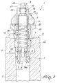
- FIG. 2 illustrates a second embodiment of the invention, in which the valve assembly 1 is of the direct-action type with the function of preventing the emptying of the circuit C.
- the second portion is constituted by a contoured bush 19, which has an externally threaded end portion for coupling to the first portion 2a and in which the central hole has a transverse cross-section that is smaller than the cross-section of the piston only in a portion that is interposed between said piston and the second end of the valve body 2.
- the adjustment means 9 comprise a stem 20, which is prism-shaped at least proximate to the end that protrudes into the valve body 2, and is inserted within a corresponding opening provided in the piston 8, the piston and the stem 20 being associated by means of a side-fitting coupling.
- the bush 19 is contoured internally so as to form an abutment shoulder for the prism-shaped portion of the stem 20.
- the piston 8 is constituted by a cylinder that is provided with a tab that protrudes from its face that is associated with the spring 7 and fits between the turns of said spring.
- a nut 21 for locking in abutment on the bush 19 is screwed onto the end of the stem 20 that protrudes from said bush.
- the sealing means 10 are constituted by a sealing ring 22, which is interposed between the bush 19 and the stem 20, the hole of said bush being provided with a circumferential groove for accommodating the sealing ring 21 proximate to the second end.
- the additional sealing means 11 are provided and are constituted by an additional sealing ring 23, which is interposed between the portions 2a and 2b and is accommodated in a slot that is formed on the face of the first portion 2a that faces the second portion 2b.
- the intake port 3 is formed at the end of the first portion 2a that protrudes into the receptacle A, while the discharge port 4 is formed by a transverse opening that is formed along the first portion.
- valve assembly 1 has a tubular element 24, which is accommodated slidingly within the portions 2a and 2b and is provided with a first flared end, which protrudes from the first portion 2a and engages the intake port 3, and with a second end, which is arranged opposite the first one and is associated with the piston 8.
- the tubular element 24 is contoured so as to form the seat 5 in an intermediate position between said ends and is provided with a transverse through opening 25, which is interposed between the seat 5 and the second end of the element and is connected to the discharge port 4.
- valve assembly 1 is provided with second elastic compression means, which are constituted by a second helical spring 26, which is interposed between the first portion 2a and the tubular element 24, in order to keep the element in abutment against the intake port 3.
- second elastic compression means which are constituted by a second helical spring 26, which is interposed between the first portion 2a and the tubular element 24, in order to keep the element in abutment against the intake port 3.
- the tubular element 24 has, at its first end, a surface 24a that is exposed to the discharge pressure and is sized so that when the working pressure inside the circuit decreases, the action applied by the discharge pressure to said surface overcomes the resistance of the second spring 26 and causes the sliding of said element, together with the piston 8, the spring 7 and the flow control element 6, away from the intake port 3, connecting said intake port to the discharge port 4 so as to allow the reverse flow of the oil from the discharge duct S to the circuit C.
- the piston 8 is threaded externally for coupling to the tubular element 24, which is associated with an internal thread at its second end.
- the limiting means 12 are constituted by the end of said internal thread.
- abutment elements are provided in order to prevent the relative rotation of the tubular element 24 with respect to the valve body 2.
- valve assembly 1 is of the pilot-operated type, preferably with an emptying-check function.
- the seat 5 is formed by the first portion 2a, which is constituted by three consecutive tubular sections that have diameters that decrease toward the seats.
- the limiting means 12 are constituted by the shoulder that protrudes inside the first portion 2a and is formed at the connection between two consecutive sections.
- the second portion 2b consists of an externally threaded bush 27, which is screwed into the hole of the first portion 2a, which is threaded at least at said bush.
- the central hole of the bush 27 has a constant cross-section that is smaller than the cross-section of the piston 8.
- the bush 27 is fully inserted in the hole of the first portion 2a, which has a shoulder for the abutment of the bush; on the opposite side of the shoulder there are two elastic safety rings 28, which are interposed between the bush 27 and the first portion 2a in order to couple said bush in a longitudinal direction.
- the adjustment means 9 comprise a threaded stem 29, in which the shank is inserted in the central hole of the bush 27 and is associated with the piston 8, the bush 27 being threaded internally.
- the bush 27 and the stem 29 are associated by means of a threaded coupling.
- a locking nut 30 is screwed onto the stem 29 in abutment against the bush 27.
- the piston 8 and the spring 7 are accommodated between the portions 2a and 2b.
- the sealing means 10 are constituted by a sealing ring 31, which is interposed between the piston 8 and the internal wall of the intermediate section of the first portion 2a.
- the piston 8 has a recess, in which the first turns of the spring 7 are inserted, on the face that is directed toward said spring, and has a lateral groove for accommodating the sealing ring 31.
- the valve body 2 further comprises a third portion 2c, which is arranged at its first end and is contoured so as to form the intake port 3 and a second seat 32 at said intake port.
- valve assembly 1 comprises a second flow control element 33, which is accommodated between the portions 2a and 2c and can engage by abutment the second seat 32.
- the second flow control element 33 is shaped like a sort of cup, in which the bottom is directed toward the intake port 3 and is open in order to connect the flow control element 6, which acts as a pilot, to the oil at the working pressure, so as to determine the pilot driving pressure of the valve assembly 1 in the chamber delimited by the second flow control element 33 and the first portion 2a.
- the second flow control element 33 is associated hermetically with the first portion 2a by interposing sealing elements 35 such as rings or the like.
- the discharge port 4 is formed by a transverse opening provided in the third portion 2c on the opposite side with respect to the intake port 3 relative to the second seat 32.
- third elastic compression means are provided which are constituted by a third helical spring 36, which is interposed between the first portion 2a and the second flow control element 33 in order to keep said flow control element in abutment against the second seat 32.
- the second flow control element 33 is provided with an annular surface 33a that is exposed to the discharge pressure in order to allow the emptying-check function according to a known operating method.
- valve assemblies 1 The operation of the valve assemblies 1 according to the invention is similar to the operation of conventional pressure relief valves of the direct-action or pilot-operated type, optionally with an emptying-check function, and therefore is not described in detail.
Landscapes
- Engineering & Computer Science (AREA)
- General Engineering & Computer Science (AREA)
- Mechanical Engineering (AREA)
- Safety Valves (AREA)
Applications Claiming Priority (2)
| Application Number | Priority Date | Filing Date | Title |
|---|---|---|---|
| ITMO20040045 | 2004-02-27 | ||
| ITMO20040045 ITMO20040045A1 (it) | 2004-02-27 | 2004-02-27 | Gruppo valvola di massima pressione |
Publications (1)
| Publication Number | Publication Date |
|---|---|
| EP1568923A1 true EP1568923A1 (de) | 2005-08-31 |
Family
ID=34746725
Family Applications (1)
| Application Number | Title | Priority Date | Filing Date |
|---|---|---|---|
| EP05101345A Withdrawn EP1568923A1 (de) | 2004-02-27 | 2005-02-22 | Druckentlastungsventil |
Country Status (2)
| Country | Link |
|---|---|
| EP (1) | EP1568923A1 (de) |
| IT (1) | ITMO20040045A1 (de) |
Cited By (4)
| Publication number | Priority date | Publication date | Assignee | Title |
|---|---|---|---|---|
| CN109707884A (zh) * | 2019-02-19 | 2019-05-03 | 沈阳远大压缩机有限公司 | 往复式气体压缩机气缸液击压力释放阀 |
| CN113417902A (zh) * | 2021-07-27 | 2021-09-21 | 景津环保股份有限公司 | 一种插装溢流阀及相应阀块 |
| WO2022145124A1 (ja) * | 2020-12-28 | 2022-07-07 | 川崎重工業株式会社 | チェック機能付きリリーフ弁 |
| CN115539643A (zh) * | 2022-10-10 | 2022-12-30 | 华能辽宁清洁能源有限责任公司 | 一种适用于高粘度齿轮的插装压力阀组 |
Citations (7)
| Publication number | Priority date | Publication date | Assignee | Title |
|---|---|---|---|---|
| US2980132A (en) * | 1957-11-25 | 1961-04-18 | Borg Warner | Safety relief valve |
| US4228818A (en) * | 1978-05-01 | 1980-10-21 | Victor Fluid Power | Crossover relief valve |
| JPS6162682A (ja) * | 1984-09-03 | 1986-03-31 | Daikin Ind Ltd | リリ−フ弁 |
| US4588163A (en) * | 1983-03-10 | 1986-05-13 | Dana Corporation | Valve stem travel limiting apparatus |
| DE19524900A1 (de) * | 1995-07-08 | 1997-01-16 | Rexroth Mannesmann Gmbh | Vorgesteuertes Druckbegrenzungsventil |
| EP0823576A2 (de) * | 1996-08-05 | 1998-02-11 | Brueninghaus Hydromatik Gmbh | Hydraulikventil mit Druckbegrenzungs- und Einspeisefunktion |
| US6499296B1 (en) * | 1998-07-24 | 2002-12-31 | Mannesmann Rexroth Ag | Hydraulic circuit |
-
2004
- 2004-02-27 IT ITMO20040045 patent/ITMO20040045A1/it unknown
-
2005
- 2005-02-22 EP EP05101345A patent/EP1568923A1/de not_active Withdrawn
Patent Citations (7)
| Publication number | Priority date | Publication date | Assignee | Title |
|---|---|---|---|---|
| US2980132A (en) * | 1957-11-25 | 1961-04-18 | Borg Warner | Safety relief valve |
| US4228818A (en) * | 1978-05-01 | 1980-10-21 | Victor Fluid Power | Crossover relief valve |
| US4588163A (en) * | 1983-03-10 | 1986-05-13 | Dana Corporation | Valve stem travel limiting apparatus |
| JPS6162682A (ja) * | 1984-09-03 | 1986-03-31 | Daikin Ind Ltd | リリ−フ弁 |
| DE19524900A1 (de) * | 1995-07-08 | 1997-01-16 | Rexroth Mannesmann Gmbh | Vorgesteuertes Druckbegrenzungsventil |
| EP0823576A2 (de) * | 1996-08-05 | 1998-02-11 | Brueninghaus Hydromatik Gmbh | Hydraulikventil mit Druckbegrenzungs- und Einspeisefunktion |
| US6499296B1 (en) * | 1998-07-24 | 2002-12-31 | Mannesmann Rexroth Ag | Hydraulic circuit |
Non-Patent Citations (1)
| Title |
|---|
| PATENT ABSTRACTS OF JAPAN vol. 010, no. 227 (M - 505) 7 August 1986 (1986-08-07) * |
Cited By (6)
| Publication number | Priority date | Publication date | Assignee | Title |
|---|---|---|---|---|
| CN109707884A (zh) * | 2019-02-19 | 2019-05-03 | 沈阳远大压缩机有限公司 | 往复式气体压缩机气缸液击压力释放阀 |
| CN109707884B (zh) * | 2019-02-19 | 2024-01-23 | 沈阳远大压缩机有限公司 | 往复式气体压缩机气缸液击压力释放阀 |
| WO2022145124A1 (ja) * | 2020-12-28 | 2022-07-07 | 川崎重工業株式会社 | チェック機能付きリリーフ弁 |
| US20240052938A1 (en) * | 2020-12-28 | 2024-02-15 | Kawasaki Jukogyo Kabushiki Kaisha | Relief valve with check function |
| CN113417902A (zh) * | 2021-07-27 | 2021-09-21 | 景津环保股份有限公司 | 一种插装溢流阀及相应阀块 |
| CN115539643A (zh) * | 2022-10-10 | 2022-12-30 | 华能辽宁清洁能源有限责任公司 | 一种适用于高粘度齿轮的插装压力阀组 |
Also Published As
| Publication number | Publication date |
|---|---|
| ITMO20040045A1 (it) | 2004-05-27 |
Similar Documents
| Publication | Publication Date | Title |
|---|---|---|
| AU630996B2 (en) | Pressure limiting valve with teflon seal | |
| US7392823B2 (en) | Combination valve | |
| US20010032675A1 (en) | Bi-directional pressure relief valve | |
| US4727792A (en) | Hydraulic holding valve | |
| CN111828723B (zh) | 比例液压阀 | |
| WO2010125500A2 (en) | Pressure relief valve | |
| US6079519A (en) | Combined fill and relief valve | |
| EP3421847B1 (de) | Sicherheitsbypassventil | |
| US20240141969A1 (en) | Vibration damper having a hydraulic connection | |
| US7331361B2 (en) | Pressure relief valve with direct hydraulic damping | |
| RU2638430C2 (ru) | Линейный картридж главной ступени для регулировки давления | |
| US4716928A (en) | Pressure-relief valve devices | |
| US3482594A (en) | Pressure relief valve | |
| US4790347A (en) | Pressure-relief valve devices | |
| EP1672259B1 (de) | Sicherheitsventilvorrichtung | |
| EP1568923A1 (de) | Druckentlastungsventil | |
| CN101469726A (zh) | 叠加式减压阀 | |
| HU208563B (en) | Pressure-limiting valve with stepped piston or double piston | |
| JPH0243042B2 (de) | ||
| US4248265A (en) | Adjustable relief valve | |
| US5159872A (en) | Valve units for use in hydraulic control systems of mining equipment | |
| GB1569854A (en) | Combined relief valve and non-return valve | |
| GB2105004A (en) | Control and relief valve | |
| CZ280815B6 (cs) | Pojistný ventil k ochraně hydraulických jednotek | |
| AU2013273691B2 (en) | Excess Pressure Safety Relief Valve |
Legal Events
| Date | Code | Title | Description |
|---|---|---|---|
| PUAI | Public reference made under article 153(3) epc to a published international application that has entered the european phase |
Free format text: ORIGINAL CODE: 0009012 |
|
| AK | Designated contracting states |
Kind code of ref document: A1 Designated state(s): AT BE BG CH CY CZ DE DK EE ES FI FR GB GR HU IE IS IT LI LT LU MC NL PL PT RO SE SI SK TR |
|
| AX | Request for extension of the european patent |
Extension state: AL BA HR LV MK YU |
|
| STAA | Information on the status of an ep patent application or granted ep patent |
Free format text: STATUS: THE APPLICATION HAS BEEN WITHDRAWN |
|
| 18W | Application withdrawn |
Effective date: 20051216 |