EP1568841A1 - A door mounting assembly - Google Patents
A door mounting assembly Download PDFInfo
- Publication number
- EP1568841A1 EP1568841A1 EP05003872A EP05003872A EP1568841A1 EP 1568841 A1 EP1568841 A1 EP 1568841A1 EP 05003872 A EP05003872 A EP 05003872A EP 05003872 A EP05003872 A EP 05003872A EP 1568841 A1 EP1568841 A1 EP 1568841A1
- Authority
- EP
- European Patent Office
- Prior art keywords
- frame
- door
- sub
- assembly
- existing
- Prior art date
- Legal status (The legal status is an assumption and is not a legal conclusion. Google has not performed a legal analysis and makes no representation as to the accuracy of the status listed.)
- Withdrawn
Links
Images


Classifications
-
- E—FIXED CONSTRUCTIONS
- E06—DOORS, WINDOWS, SHUTTERS, OR ROLLER BLINDS IN GENERAL; LADDERS
- E06B—FIXED OR MOVABLE CLOSURES FOR OPENINGS IN BUILDINGS, VEHICLES, FENCES OR LIKE ENCLOSURES IN GENERAL, e.g. DOORS, WINDOWS, BLINDS, GATES
- E06B1/00—Border constructions of openings in walls, floors, or ceilings; Frames to be rigidly mounted in such openings
- E06B1/04—Frames for doors, windows, or the like to be fixed in openings
- E06B1/34—Coverings, e.g. protecting against weather, for decorative purposes
- E06B1/347—Renovation door frames covering the existing old frames
-
- E—FIXED CONSTRUCTIONS
- E06—DOORS, WINDOWS, SHUTTERS, OR ROLLER BLINDS IN GENERAL; LADDERS
- E06B—FIXED OR MOVABLE CLOSURES FOR OPENINGS IN BUILDINGS, VEHICLES, FENCES OR LIKE ENCLOSURES IN GENERAL, e.g. DOORS, WINDOWS, BLINDS, GATES
- E06B1/00—Border constructions of openings in walls, floors, or ceilings; Frames to be rigidly mounted in such openings
- E06B1/02—Base frames, i.e. template frames for openings in walls or the like, provided with means for securing a further rigidly-mounted frame; Special adaptations of frames to be fixed therein
Definitions
- This invention relates to a door mounting assembly which enables a door to be mounted to an existing door frame.
- window and door systems account for over half of all joinery sales, both as systems for fitting to new buildings, and as replacement systems for existing buildings.
- a door mounting assembly which enables a rectangular door to be mounted to an existing, incompatible, rectangular door frame, the assembly comprising a sub-frame for fitting into the existing door frame along at least its two opposite vertical edges and at least two edge members for fitting respectively along the two opposite vertical edges of the door, the edge members co-operating with the sub-frame when the door is closed.
- each of the sub-frame and edge members are rebated such that a portion of the sub-frame overlaps the edge members on one side of the door and a portion of the edge members overlap the sub-frame on the opposite side of the door.
- FIG. 10 a first embodiment of a door mounting assembly according to the present invention, generally indicated as 10, for use in mounting a rectangular door 12 in an otherwise incompatible existing rectangular door frame 14.
- the door 12 illustrated is of composite form, having a core sandwich between two sheets of veneer or the like, although the door 12 could of course be formed of solid timber, or any other suitable material.
- the assembly 10 comprises an outer sub-frame 16 for fitting into the existing door frame 14, and an inner frame 18 for mounting to the edges of the door 12, the inner frame 18 being shaped and dimensioned for a co-operative fit with the sub-frame 16 as will be described.
- the sub-frame 16 preferably comprises four outer frame members 20 of substantially constant cross-section and mitred end to end to form a rectangular frame surrounding the door 12 on all four sides.
- the inner frame 18 preferably consists of four edge members 22 of substantially constant cross-section, one mounted along each edge of the door 12 and mitred at the corners, for co-operation with the corresponding outer frame members 20 of the sub-frame 16.
- outer and inner frame members 20 and 22 could simply be located along the hinged edge and the opposite edge of the door 12 (i.e. its vertical edges) in order to allow the door 12 to be mounted to the existing door frame 14.
- a satisfactory seal would not therefore be created between the top edge of the door 12 and the corresponding portion of the door frame 14, and the underside of the door 12.
- the outer frame members 20 and the edge members 22 each form a closed rectangle surrounding the door 12 on all sides.
- one edge member 22 is connected by hinges 24 to the adjacent outer frame member 20.
- the sub-frame 16 can be quickly and easily secured to the existing door frame 14, as will be described in detail hereinafter, and the door 12, having the inner frame 18 forming a rim therearound, be quickly and easily hingedly mounted to the sub-frame 16, and therefore the existing door frame 14.
- the sub-frame 16 and inner frame 18 are correspondingly shaped such as to provide a preferably weather-proof seal between the door 12 and the outer frame 16.
- each outer frame member 20, in section is substantially Z-shaped, consisting of a first, hollow, section 26 and a second section 30 in parallel spaced relation to one another, and joined by a third section 28 extending therebetween.
- Each outer frame member is preferably manufactured from profiled aluminium or a pvc extrusion, or indeed a combination of both, although it will of course be appreciated that the outer frame members 20 could be formed from a number of individual components suitably joined to provide the configuration shown.
- Each edge member 22 is also substantially Z-shaped in cross section, comprising a first leg 32, a second leg 34 extending therefrom and substantially perpendicular thereto, and a third leg 36 extending from a second leg 34, again substantially perpendicularly thereto.
- the edge members 22 are also formed in similar fashion to the outer frame members 20 for example by extrusion. In order to fit the edge members 22 to the door 12, the edges of the door 12 must be machined with a similar if not identical profile to that of the edge member 22, in order to securely receive same.
- the co-operating cross sections of the sub-frame 16 and the inner frame 18 provide a double rebate between each edge of the door 12 and the corresponding section of the sub-frame 16.
- the first section 26 and the third section 28 form a first rebate overlapping the edge member 22 and door 12 on one face of the latter, while the first leg 32 and the second leg 34 form a second rebate, overlapping the third section 30 of the outer frame member 20.
- a first channel 40 is also preferably provided in the first section 26, for carrying a strip seal or gasket (not shown) of conventional form for sealing against the door 12, while a second channel 42 is provided between the second leg 34 and third leg 36, again for carrying a conventional strip seal or gasket (not shown) for sealing against the section 30.
- first channel 40 and second channel 42 could be repositioned as desired or indeed any other suitable sealing means could be utilised between the door 12 and the sub-frame 16.
- the sub-frame 16 is mounted in the existing door frame 14. This is achieved by passing fixing means in the form of screws 44 through both the second section 28 and third section 30 of each outer frame member 20, directly into the existing door frame 14. Sliding blocks 45 may be used in order to increase the area of the second section 28 on which the respective screws 44 act. Also, spacers (not shown) may be inserted between each outer frame member 20 and the adjacent portion of the existing door frame 14, i.e. in the gap behind the section 28, to ensure a desired separation between the two according to the width of door to be fitted. It will of course also be understood that any other suitable fixing means could be used, such as an adhesive, to secure the sub-frame 16 to the existing door frame 14.
- the existing door frame 14 will also normally include a channel 46 for receiving a strip seal or gasket (not shown), and such a gasket should be utilised to form a seal between the door frame 14 and the sub-frame 16.
- the door frame 14 is preferably provided with a thermal break (not shown) within the main cavity thereof.
- a suitable profile must be machined along the edges of the door 12, preferably using a purpose designed routing bit (not shown).
- each member is then secured in place by means of a plurality of screws 44 passing through the first leg 32 and the third leg 36. Again, the position and orientation of the screws 44 is not essential and could be altered as required or desired. Furthermore, the screws 44 could be replaced with any other suitable fixing means, again for example an adhesive or the like.
- the hinges 24 need not be of the form illustrated, and could be of any other suitable shape and/or configuration.
- the door 12 is mounted, it is then necessary to be able to retain the door 12 in the closed position, and to lock the door 12 if necessary, which will conventionally be achieved by means of a lock assembly 48 housed within one side of the door 12, generally opposite to the hinge 24 as illustrated in figure 4.
- a lock assembly 48 housed within one side of the door 12, generally opposite to the hinge 24 as illustrated in figure 4.
- the second section 28 of the respective outer frame member 20 is provided with a channel 49 for receiving a latch bolt 50 of the lock assembly 48, in order to allow the door 12 to be held in the closed position, in conventional fashion.
- the channel 49 may also receive a dead bolt (not shown) in order to allow the door 12 to be locked using a key or the like.
- a suitably shaped and dimensioned aperture may be provided in the second section 28, within the channel 49, in order to allow the latch bolt 50 and/or dead bolt (not shown) to pass through the second section 28, possibly into a similar channel in the existing door frame 14.
- FIG 5 there is illustrated a second embodiment of a mounting assembly according to the present invention, generally indicated as 110, again for mounting a door 112 to an existing door frame 114.
- the assembly 110 again comprises an outer sub-frame 116 and an inner frame 118, the sub-frame 116 being mounted within the door frame 114, while the inner frame 118 is mounted around the edges of the door 112.
- the outermost portion of the outer frame member 120 is preferably detachable, in order to allow fixing screws (not shown) or the like to be passed through the outer frame member 120 and into the door frame 114.
- the main difference with the second embodiment is the provision of adjustment means in the form of a plate 60 mounted on the outside of the outer frame member 120 between the door frame 114 and the sub-frame 116.
- the plate 60 is preferably provided with a ball 62 at one end thereof, housed within a correspondingly shaped socket 64 in the outer frame member 20, such that the plate 60 may be hinged relative to the outer frame member 120.
- the outer frame member 120 is also provided with a threaded aperture 66 for receiving a correspondingly threaded grub screw (not shown) or the like accessible from the inside of the sub-frame.
- the plate 60 is preferably formed from a material which will create a thermal break between the door frame 114 and the outer frame 116.
- the mounting assembly 10;110 of the present invention allows the secure weather tight fitting of almost any square edged door into an existing frame, quickly and easily.
- a door may be prepared off site by securing the inner frame 18; 118 thereto, then hingedly mounting the outer sub-frame 16; 116 thereto, before shipping the door to the required site.
- a pvc or aluminium door frame, matching the other doors/windows can be fitted prior to the arrival of the door and mounting assembly 10;110, which can then be quickly and easily secured in place.
- the double rebate, and consequent space available between the outer frame 16;116 and the inner frame 18; 118 provides a significant margin of error, and therefore increases the speed of on-site fittings.
- the mounting assembly 10;110 allows a new door to be fitted to an existing door frame, thereby drastically reducing the price of replacing a door, as it will no longer be necessary to replace the whole frame to fit a particular door, as is normally the case.
Abstract
Description
- This invention relates to a door mounting assembly which enables a door to be mounted to an existing door frame.
- In Ireland, window and door systems account for over half of all joinery sales, both as systems for fitting to new buildings, and as replacement systems for existing buildings.
- There are a large number of pvc window and door systems available on the market, with each system generally being produced by a plastics extruder and then sold onto a manufacturer who may sell directly to the public or may sell to a number of individual companies who supply and fit to the end user. Pvc profiles from different manufacturers are broadly similar in overall dimensions, but are unique in many ways. Pvc door systems, although popular, do have a number of drawbacks, with stability, security, and also importantly to the consumer, aesthetics. Thus an increasingly popular alternative to pvc doors are composite doors, as such doors have the low maintenance appeal of pvc doors, with the look and feel of timber.
- However, it is both expensive and time consuming to adapt a composite door or indeed a conventional timber door, to each and every pvc frame system on the market. As a solution, some composite door manufacturers develop their own pvc frame systems suitable for use with a particular composite door. Although in theory this seems like an adequate solution, when a pvc joinery manufacturer wishes to put, for example, side screens or windows beside or around the composite door and corresponding frame, more often than not the frames will not match in colour/style and will not connect together properly to form a sufficient seal. Obviously the manufacturers and fitters of pvc joinery systems do not wish to sell or fit a system that is not easy to install. They would like the composite doors to fit their own frame systems, thus giving more control over the final product, reducing the cost, and improving the overall aesthetic effect.
- It is therefore an object of the present invention to provide a door mounting assembly which enables a door to be mounted to an existing door frame.
- According to the present invention there is provided a door mounting assembly which enables a rectangular door to be mounted to an existing, incompatible, rectangular door frame, the assembly comprising a sub-frame for fitting into the existing door frame along at least its two opposite vertical edges and at least two edge members for fitting respectively along the two opposite vertical edges of the door, the edge members co-operating with the sub-frame when the door is closed.
- Preferably, each of the sub-frame and edge members are rebated such that a portion of the sub-frame overlaps the edge members on one side of the door and a portion of the edge members overlap the sub-frame on the opposite side of the door.
- Embodiments of the present invention will now be described with reference to the accompanying drawings, in which:
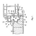
- Figure 1 is a sectioned view of a door mounting assembly according to a first embodiment of the invention, mounted to an existing door frame, and carrying a composite door.
- Figure 2 is a sectioned view of a sub-frame and an edge member forming elements of the door mounting assembly of figure 1;
- Figure 3 is a similar sectioned view to that of figure 1, wherein various components have been secured by means of a plurality of screws;
- Figure 4 is a sectioned view of a door mounted to an existing door frame by means of the embodiment of door mounting assembly of Figures 1 to 3; and
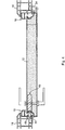
- Figure 5 is a sectioned view of an alternative embodiment of the door mounting assembly of the present invention.
-
- Referring now to figures 1 to 4 of the accompanying drawings, there is illustrated a first embodiment of a door mounting assembly according to the present invention, generally indicated as 10, for use in mounting a
rectangular door 12 in an otherwise incompatible existingrectangular door frame 14. Thedoor 12 illustrated is of composite form, having a core sandwich between two sheets of veneer or the like, although thedoor 12 could of course be formed of solid timber, or any other suitable material. Theassembly 10 comprises anouter sub-frame 16 for fitting into the existingdoor frame 14, and aninner frame 18 for mounting to the edges of thedoor 12, theinner frame 18 being shaped and dimensioned for a co-operative fit with thesub-frame 16 as will be described. Thesub-frame 16 preferably comprises fourouter frame members 20 of substantially constant cross-section and mitred end to end to form a rectangular frame surrounding thedoor 12 on all four sides. Likewise, theinner frame 18 preferably consists of fouredge members 22 of substantially constant cross-section, one mounted along each edge of thedoor 12 and mitred at the corners, for co-operation with the correspondingouter frame members 20 of thesub-frame 16. It will however be appreciated that outer andinner frame members door 12 to be mounted to the existingdoor frame 14. However, a satisfactory seal would not therefore be created between the top edge of thedoor 12 and the corresponding portion of thedoor frame 14, and the underside of thedoor 12. It is therefore preferable, particularly with exterior doors, that theouter frame members 20 and theedge members 22 each form a closed rectangle surrounding thedoor 12 on all sides. - Obviously, in order to allow conventional hinged opening of the
door 12, oneedge member 22 is connected byhinges 24 to the adjacentouter frame member 20. Thus thesub-frame 16 can be quickly and easily secured to the existingdoor frame 14, as will be described in detail hereinafter, and thedoor 12, having theinner frame 18 forming a rim therearound, be quickly and easily hingedly mounted to thesub-frame 16, and therefore the existingdoor frame 14. As mentioned above, and as will be described hereinafter in detail, thesub-frame 16 andinner frame 18 are correspondingly shaped such as to provide a preferably weather-proof seal between thedoor 12 and theouter frame 16. - Referring in particular to figure 2, it can be seen that each
outer frame member 20, in section, is substantially Z-shaped, consisting of a first, hollow,section 26 and asecond section 30 in parallel spaced relation to one another, and joined by athird section 28 extending therebetween. Each outer frame member is preferably manufactured from profiled aluminium or a pvc extrusion, or indeed a combination of both, although it will of course be appreciated that theouter frame members 20 could be formed from a number of individual components suitably joined to provide the configuration shown. - Each
edge member 22 is also substantially Z-shaped in cross section, comprising afirst leg 32, asecond leg 34 extending therefrom and substantially perpendicular thereto, and athird leg 36 extending from asecond leg 34, again substantially perpendicularly thereto. Theedge members 22 are also formed in similar fashion to theouter frame members 20 for example by extrusion. In order to fit theedge members 22 to thedoor 12, the edges of thedoor 12 must be machined with a similar if not identical profile to that of theedge member 22, in order to securely receive same. - The co-operating cross sections of the
sub-frame 16 and theinner frame 18 provide a double rebate between each edge of thedoor 12 and the corresponding section of thesub-frame 16. Specifically, thefirst section 26 and thethird section 28 form a first rebate overlapping theedge member 22 anddoor 12 on one face of the latter, while thefirst leg 32 and thesecond leg 34 form a second rebate, overlapping thethird section 30 of theouter frame member 20. To ensure a fully weatherproof seal between thedoor 12 and thesub-frame 16, afirst channel 40 is also preferably provided in thefirst section 26, for carrying a strip seal or gasket (not shown) of conventional form for sealing against thedoor 12, while asecond channel 42 is provided between thesecond leg 34 andthird leg 36, again for carrying a conventional strip seal or gasket (not shown) for sealing against thesection 30. It will of course be appreciated that either or both of thefirst channel 40 andsecond channel 42 could be repositioned as desired or indeed any other suitable sealing means could be utilised between thedoor 12 and thesub-frame 16. - Thus, in order to mount the
door 12 using themounting assembly 10 of the present invention, thesub-frame 16 is mounted in the existingdoor frame 14. This is achieved by passing fixing means in the form ofscrews 44 through both thesecond section 28 andthird section 30 of eachouter frame member 20, directly into the existingdoor frame 14.Sliding blocks 45 may be used in order to increase the area of thesecond section 28 on which therespective screws 44 act. Also, spacers (not shown) may be inserted between eachouter frame member 20 and the adjacent portion of the existingdoor frame 14, i.e. in the gap behind thesection 28, to ensure a desired separation between the two according to the width of door to be fitted. It will of course also be understood that any other suitable fixing means could be used, such as an adhesive, to secure thesub-frame 16 to the existingdoor frame 14. The existingdoor frame 14 will also normally include achannel 46 for receiving a strip seal or gasket (not shown), and such a gasket should be utilised to form a seal between thedoor frame 14 and thesub-frame 16. In addition, thedoor frame 14 is preferably provided with a thermal break (not shown) within the main cavity thereof. - In order to mount the
inner frame 18 to thedoor 12, as described above, a suitable profile must be machined along the edges of thedoor 12, preferably using a purpose designed routing bit (not shown). Once theedge members 22 have been pressed into place around the edges of thedoor 12, each member is then secured in place by means of a plurality ofscrews 44 passing through thefirst leg 32 and thethird leg 36. Again, the position and orientation of thescrews 44 is not essential and could be altered as required or desired. Furthermore, thescrews 44 could be replaced with any other suitable fixing means, again for example an adhesive or the like. Once theinner frame 18 has been fitted to thedoor 12, the combineddoor 12 andinner frame 18 is then mounted to thesub-frame 16 by means of thehinges 24. It will of course be understood that thehinges 24 need not be of the form illustrated, and could be of any other suitable shape and/or configuration. - Once the
door 12 is mounted, it is then necessary to be able to retain thedoor 12 in the closed position, and to lock thedoor 12 if necessary, which will conventionally be achieved by means of alock assembly 48 housed within one side of thedoor 12, generally opposite to thehinge 24 as illustrated in figure 4. Thus thesecond section 28 of the respectiveouter frame member 20 is provided with achannel 49 for receiving alatch bolt 50 of thelock assembly 48, in order to allow thedoor 12 to be held in the closed position, in conventional fashion. Thechannel 49 may also receive a dead bolt (not shown) in order to allow thedoor 12 to be locked using a key or the like. If necessary, a suitably shaped and dimensioned aperture (not shown) may be provided in thesecond section 28, within thechannel 49, in order to allow thelatch bolt 50 and/or dead bolt (not shown) to pass through thesecond section 28, possibly into a similar channel in the existingdoor frame 14. - Referring now to figure 5, there is illustrated a second embodiment of a mounting assembly according to the present invention, generally indicated as 110, again for mounting a
door 112 to an existingdoor frame 114. In this second embodiment, like components have been accorded like reference numerals plus 100, and unless otherwise stated, perform a like function. Theassembly 110 again comprises anouter sub-frame 116 and aninner frame 118, thesub-frame 116 being mounted within thedoor frame 114, while theinner frame 118 is mounted around the edges of thedoor 112. The outermost portion of theouter frame member 120 is preferably detachable, in order to allow fixing screws (not shown) or the like to be passed through theouter frame member 120 and into thedoor frame 114. - The main difference with the second embodiment is the provision of adjustment means in the form of a
plate 60 mounted on the outside of theouter frame member 120 between thedoor frame 114 and thesub-frame 116. Theplate 60 is preferably provided with aball 62 at one end thereof, housed within a correspondingly shapedsocket 64 in theouter frame member 20, such that theplate 60 may be hinged relative to theouter frame member 120. Theouter frame member 120 is also provided with a threadedaperture 66 for receiving a correspondingly threaded grub screw (not shown) or the like accessible from the inside of the sub-frame. Thus, as the grub screw is advanced through the threadedaperture 66, it will contact theplate 60, with further advancement of the grub screw forcing theplate 60 to hinge rearwardly (anti-clockwise as seen in Fig. 5). Once the free edge of theplate 60 has contacted thedoor frame 114, any further pivoting of same will force theouter frame member 120 outwardly away from the corresponding section of thedoor frame 114, thereby allowing adjustment of the position of thesub-frame 116 relative to thedoor frame 114 prior to final fixing. Theplate 60 is preferably formed from a material which will create a thermal break between thedoor frame 114 and theouter frame 116. - It will therefore be appreciated that the mounting
assembly 10;110 of the present invention allows the secure weather tight fitting of almost any square edged door into an existing frame, quickly and easily. For example, a door may be prepared off site by securing theinner frame 18; 118 thereto, then hingedly mounting theouter sub-frame 16; 116 thereto, before shipping the door to the required site. For a new building, a pvc or aluminium door frame, matching the other doors/windows, can be fitted prior to the arrival of the door and mountingassembly 10;110, which can then be quickly and easily secured in place. The double rebate, and consequent space available between theouter frame 16;116 and theinner frame 18; 118 provides a significant margin of error, and therefore increases the speed of on-site fittings. Furthermore, as previously stated, the mountingassembly 10;110 allows a new door to be fitted to an existing door frame, thereby drastically reducing the price of replacing a door, as it will no longer be necessary to replace the whole frame to fit a particular door, as is normally the case. - The present invention is not limited to the embodiments described herein, which may be amended or modified without departing from the scope of the present invention.
Claims (10)
- A door mounting assembly which enables a rectangular door to be mounted to an existing, incompatible, rectangular door frame, the assembly comprising a sub-frame for fitting into the existing door frame along at least its two opposite vertical edges and at least two edge members for fitting respectively along the two opposite vertical edges of the door, the edge members co-operating with the sub-frame when the door is closed.
- An assembly as claimed in claim 1, wherein each of the sub-frame and edge members are rebated such that a portion of the sub-frame overlaps the edge members on one side of the door and a portion of the edge members overlap the sub-frame on the opposite side of the door.
- An assembly as claimed in claim 2, wherein the overlapping portions of the edge members and/or sub-frame are adapted to carry a resilient seal for forming a seal between the sub-frame and door when the door is closed.
- An assembly as claimed in any preceding claim, wherein one edge member is hinged to the sub-frame.
- An assembly as claimed in any preceding claim, wherein the sub-frame is rectangular and the edge members are fitted along all four edges of the door.
- An assembly as claimed in any preceding claim, wherein the sub-frame is substantially Z-shaped in cross section with first and second substantially parallel but spaced apart sections joined by a third section substantially perpendicular to each of the first and second sections.
- An assembly as claimed in any preceding claim, wherein the sub-frame comprises means for adjusting the position of the sub-frame relative to the existing door frame prior to final fixing of the sub-frame.
- An assembly as claimed in claim 7, wherein the adjusting means comprises a flap hinged to the sub-frame and extending, in use, from the outside of the sub-frame towards the existing door frame, and means accessible from the inside of the sub-frame for adjusting the angle of the flap relative to the sub-frame.
- An assembly as claimed in claim 7 or 8, wherein the adjusting means forms a thermal break between the sub-frame and existing door frame.
- A door assembly in which a rectangular door is mounted to an existing, incompatible, rectangular door frame, the assembly comprising a sub-frame fitted into the existing door frame along at least its two opposite vertical edges and at least two edge members fitted respectively along the two opposite vertical edges of the door, the edge members co-operating with the sub-frame when the door is closed.
Applications Claiming Priority (2)
| Application Number | Priority Date | Filing Date | Title |
|---|---|---|---|
| IE20040118 | 2004-02-24 | ||
| IE20040118 | 2004-02-24 |
Publications (1)
| Publication Number | Publication Date |
|---|---|
| EP1568841A1 true EP1568841A1 (en) | 2005-08-31 |
Family
ID=34746646
Family Applications (1)
| Application Number | Title | Priority Date | Filing Date |
|---|---|---|---|
| EP05003872A Withdrawn EP1568841A1 (en) | 2004-02-24 | 2005-02-23 | A door mounting assembly |
Country Status (1)
| Country | Link |
|---|---|
| EP (1) | EP1568841A1 (en) |
Cited By (2)
| Publication number | Priority date | Publication date | Assignee | Title |
|---|---|---|---|---|
| FR2905402A1 (en) * | 2006-08-31 | 2008-03-07 | Financ Yves Judel Entpr Uniper | Interior door renovating device for e.g. dwelling house, has rabbet presenting distances between posts` rabbet parts and between crosspiece`s rabbet part and ground equal to that of frame`s rabbet, and depth equal to that of frame`s rabbet |
| EP2315888A1 (en) * | 2008-08-08 | 2011-05-04 | Cir Ambiente S.p.A. | Improved panel, in particular comprising a door |
Citations (3)
| Publication number | Priority date | Publication date | Assignee | Title |
|---|---|---|---|---|
| DE7600834U1 (en) * | 1976-01-14 | 1976-05-26 | Johannes Brockmann Gmbh & Co Kg, 4250 Bottrop | LIGHT ALLOY DOOR FRAME |
| DE9308300U1 (en) * | 1993-06-03 | 1993-08-19 | Kueffner Aluzargen Gmbh | Corner frame for doors or the like |
| EP0792992A1 (en) * | 1996-02-29 | 1997-09-03 | Niemann, Hans Dieter | Retrofit door frame |
-
2005
- 2005-02-23 EP EP05003872A patent/EP1568841A1/en not_active Withdrawn
Patent Citations (3)
| Publication number | Priority date | Publication date | Assignee | Title |
|---|---|---|---|---|
| DE7600834U1 (en) * | 1976-01-14 | 1976-05-26 | Johannes Brockmann Gmbh & Co Kg, 4250 Bottrop | LIGHT ALLOY DOOR FRAME |
| DE9308300U1 (en) * | 1993-06-03 | 1993-08-19 | Kueffner Aluzargen Gmbh | Corner frame for doors or the like |
| EP0792992A1 (en) * | 1996-02-29 | 1997-09-03 | Niemann, Hans Dieter | Retrofit door frame |
Cited By (2)
| Publication number | Priority date | Publication date | Assignee | Title |
|---|---|---|---|---|
| FR2905402A1 (en) * | 2006-08-31 | 2008-03-07 | Financ Yves Judel Entpr Uniper | Interior door renovating device for e.g. dwelling house, has rabbet presenting distances between posts` rabbet parts and between crosspiece`s rabbet part and ground equal to that of frame`s rabbet, and depth equal to that of frame`s rabbet |
| EP2315888A1 (en) * | 2008-08-08 | 2011-05-04 | Cir Ambiente S.p.A. | Improved panel, in particular comprising a door |
Similar Documents
| Publication | Publication Date | Title |
|---|---|---|
| US5806256A (en) | Modular glazing system | |
| US7587876B2 (en) | Door edge construction | |
| US9091119B2 (en) | Windows and doors assembly structure having a joint portion of 45 degrees | |
| US9316041B2 (en) | Entry door clearance sidelight | |
| US4001972A (en) | Prefabricated pre-hung combination storm and screen door and method for installing the same | |
| US7971623B2 (en) | Adjustable garage door window frame and method of installation | |
| US20110120044A1 (en) | Door Edge Construction | |
| US20150267460A1 (en) | Combination Marine and Stop Frame Glazed Panel and Method for the Same | |
| CA2311142C (en) | Unitary profile for window construction | |
| RU2639626C2 (en) | Frame | |
| US20040206025A1 (en) | Casing, door or window frame, particularly for outdoor use | |
| EP1568841A1 (en) | A door mounting assembly | |
| US20220074256A1 (en) | Glazing framing system and method | |
| US8359795B2 (en) | Window cladding | |
| US6301852B1 (en) | Window glazing assembly | |
| AU2006228089B2 (en) | Window sash and window assembly | |
| GB2235232A (en) | Shower enclosure | |
| US11891851B2 (en) | Door-ready molding | |
| US20220145693A1 (en) | Door-ready molding | |
| AU770855B2 (en) | Joinery construction | |
| IES922796A2 (en) | "A sash member" | |
| WO2007070916A1 (en) | Window sash and window assembly | |
| EP1640547A1 (en) | A method of attaching a cover element to a window casement, and a cover element to be attached to a window casement | |
| GB2284004A (en) | Window structure | |
| CZ2001187A3 (en) | Construction of central connection of profiled frames of metal doors or windows having two leaves |
Legal Events
| Date | Code | Title | Description |
|---|---|---|---|
| PUAI | Public reference made under article 153(3) epc to a published international application that has entered the european phase |
Free format text: ORIGINAL CODE: 0009012 |
|
| AK | Designated contracting states |
Kind code of ref document: A1 Designated state(s): AT BE BG CH CY CZ DE DK EE ES FI FR GB GR HU IE IS IT LI LT LU MC NL PL PT RO SE SI SK TR |
|
| AX | Request for extension of the european patent |
Extension state: AL BA HR LV MK YU |
|
| 17P | Request for examination filed |
Effective date: 20060228 |
|
| AKX | Designation fees paid |
Designated state(s): AT BE BG CH CY CZ DE DK EE ES FI FR GB GR HU IE IS IT LI LT LU MC NL PL PT RO SE SI SK TR |
|
| 17Q | First examination report despatched |
Effective date: 20080901 |
|
| STAA | Information on the status of an ep patent application or granted ep patent |
Free format text: STATUS: THE APPLICATION IS DEEMED TO BE WITHDRAWN |
|
| 18D | Application deemed to be withdrawn |
Effective date: 20080901 |