EP1568663A2 - Preform station of a press-blow machine - Google Patents
Preform station of a press-blow machine Download PDFInfo
- Publication number
- EP1568663A2 EP1568663A2 EP04027162A EP04027162A EP1568663A2 EP 1568663 A2 EP1568663 A2 EP 1568663A2 EP 04027162 A EP04027162 A EP 04027162A EP 04027162 A EP04027162 A EP 04027162A EP 1568663 A2 EP1568663 A2 EP 1568663A2
- Authority
- EP
- European Patent Office
- Prior art keywords
- charging socket
- ring
- piston rod
- preform
- flange
- Prior art date
- Legal status (The legal status is an assumption and is not a legal conclusion. Google has not performed a legal analysis and makes no representation as to the accuracy of the status listed.)
- Granted
Links
- 238000001816 cooling Methods 0.000 claims description 11
- 125000006850 spacer group Chemical group 0.000 claims description 8
- 230000004323 axial length Effects 0.000 claims description 2
- 239000012530 fluid Substances 0.000 claims description 2
- 238000007789 sealing Methods 0.000 claims description 2
- 238000007496 glass forming Methods 0.000 claims 2
- 238000002788 crimping Methods 0.000 claims 1
- 230000001747 exhibiting effect Effects 0.000 claims 1
- 230000035515 penetration Effects 0.000 claims 1
- 239000007788 liquid Substances 0.000 abstract 1
- 230000008878 coupling Effects 0.000 description 10
- 238000010168 coupling process Methods 0.000 description 10
- 238000005859 coupling reaction Methods 0.000 description 10
- 230000001447 compensatory effect Effects 0.000 description 2
- 230000000694 effects Effects 0.000 description 2
- 238000000034 method Methods 0.000 description 2
- 230000036316 preload Effects 0.000 description 2
- 230000006835 compression Effects 0.000 description 1
- 238000007906 compression Methods 0.000 description 1
- 239000012809 cooling fluid Substances 0.000 description 1
- 239000006060 molten glass Substances 0.000 description 1
- 210000000056 organ Anatomy 0.000 description 1
- 230000002093 peripheral effect Effects 0.000 description 1
- 230000002040 relaxant effect Effects 0.000 description 1
Images


Classifications
-
- C—CHEMISTRY; METALLURGY
- C03—GLASS; MINERAL OR SLAG WOOL
- C03B—MANUFACTURE, SHAPING, OR SUPPLEMENTARY PROCESSES
- C03B9/00—Blowing glass; Production of hollow glass articles
- C03B9/13—Blowing glass; Production of hollow glass articles in gob feeder machines
- C03B9/193—Blowing glass; Production of hollow glass articles in gob feeder machines in "press-and-blow" machines
- C03B9/1932—Details of such machines, e.g. plungers or plunger mechanisms for the press-and-blow machine, cooling of plungers
- C03B9/1936—Hydraulic or pneumatic displacement means of the plunger
Definitions
- claims 8 and 9 relate to the establishment of a Seal for guiding a cooling fluid under the condition of the relative radial Agility of the two units to each other.
Landscapes
- Engineering & Computer Science (AREA)
- Chemical & Material Sciences (AREA)
- Mechanical Engineering (AREA)
- Manufacturing & Machinery (AREA)
- Materials Engineering (AREA)
- Organic Chemistry (AREA)
- Automatic Assembly (AREA)
- Forging (AREA)
- Processing And Handling Of Plastics And Other Materials For Molding In General (AREA)
Abstract
Description
Die Erfindung bezieht sich auf eine Vorformstation entsprechend dem Oberbegriff
des Anspruchs 1.The invention relates to a preforming station according to the preamble
of
Derartige Vorformstationen sind im Hause der Anmelderin allgemein bekannt. Sie bestehen im Wesentlichen aus einer langgestreckten, aus einem Presszylinder und einem sich zu diesem koaxial erstreckenden Stempelzylinder gebildeten, einen Pressstempelmechanismus aufnehmenden Funktionseinheit, die sich durch die Öffnung eines Maschinengehäuses hindurcherstreckt und in dieser Öffnung mit der Maßgabe gehalten ist, dass Justierbewegungen rechtwinklig zu der Längsachse der Funktionseinheit möglich sind. Zu diesem Zweck ist eine brillenartige Aufnahme vorgesehen, mittels welcher die Funktionseinheit unter axialer Federvorspannung gegenüber dem Gehäuse, insbesondere der Berandung der genannten Öffnung, gehalten ist.Such preform stations are well known in the Applicant's home. They consist essentially of an elongated, from a press cylinder and a stamp cylinder extending coaxially therewith, a press-stamp mechanism receiving functional unit, the extends through the opening of a machine housing and in this Opening is provided with the proviso that adjusting movements at right angles are possible to the longitudinal axis of the functional unit. For this purpose is provided a spectacle-like receptacle, by means of which the functional unit under axial spring preload with respect to the housing, in particular the Boundary of said opening, is held.
Ausgleichsbewegungen rechtwinklig zu der Längsachse der Funktionseinheit
sind erforderlich mit Hinblick auf eine exakte zentrische Führung des
Pressstempels relativ zu einem oberhalb dieser Funktionseinheit befindlichen
Mündungswerkzeug einer Vorform. Funktionseinheiten dieser Art können einzeln
in den genannten brillenartigen Aufnahmen angeordnet sein - es können
jedoch auch zwei oder mehrere solcher Funktionseinheiten über brillenartige
Aufnahmen zusammengefasst sein. Charakteristisch für diese Ausführungsform
ist in jedem Fall, dass ein Zentrieren des Pressstempels relativ zu einem
Mündungswerkzeug Bewegungen der gesamten Masse der Funktionseinheit
erfordert und bereits aus diesem Grund mit einem dementsprechenden Kraftaufwand
verbunden ist. Erschwert wird eine radiale Zentrierungsbewegung ferner
durch den Umstand, dass die Funktionseinheit in Achsrichtung unter Federvorspannung
steht. Hiermit in Zusammenhang stehende Reibungskräfte
bringen einen beträchtlichen Verschleiß mit sich.
Hinzutritt ein weiterer Nachteil, der bei einer Zusammenfassung mehrerer
Funktionseinheiten in den genannten Aufnahmen gegeben ist, da in diesen
Fällen individuelle Zentrierungen der einzelnen Funktionseinheiten nicht möglich
sind. Dieser Umstand kann sich ebenfalls verschleißerhöhend auswirken.Compensating movements perpendicular to the longitudinal axis of the functional unit are required with regard to an exact centric guidance of the press ram relative to a preform mold located above this functional unit. Functional units of this kind can be arranged individually in the spectacle-like receptacles mentioned above - however, two or more such functional units can also be combined via spectacle-like receptacles. In any case, it is characteristic of this embodiment that centering of the press ram relative to a necking tool requires movements of the entire mass of the functional unit and for this reason alone is associated with a corresponding expenditure of force. A radial centering movement is further complicated by the fact that the functional unit is spring-biased in the axial direction. Related friction forces involve significant wear.
Addition of another disadvantage, which is given in a summary of several functional units in the above recordings, since in these cases individual centering of the individual functional units are not possible. This circumstance can also increase the wear.
Es ist vor diesem Hintergrund die Aufgabe der Erfindung, eine Vorformstation der eingangs bezeichneten Art mit Hinblick auf genauere, insbesondere leichtgängigere Zentrierungsbewegungen hin auszugestalten, und zwar bei gleichzeitig vermindertem Verschleiß.It is against this background the object of the invention, a preforming station the type described at the beginning with regard to more accurate, in particular smoother Centering movements, at the same time reduced wear.
Gelöst ist diese Aufgabe bei einer solchen Funktionseinheit durch die Merkmale
des Anspruchs 1.This problem is solved in such a functional unit by the features
of
Erfindungswesentlich ist hiernach, dass die Vorformstation in zwei Einheiten bzw. Baugruppen unterteilt ist, von denen die eine gegenüber der Vorform radial ausrichtbar ist, wohingegen die andere maschinenfest angeordnet ist. Gegenüber dem eingangs dargelegten Stand der Technik müssen somit für ein Ausrichten wesentlich geringere Massen bewegt werden, so dass ein dementsprechend geringerer Kraftaufwand erforderlich ist. Auch wird der Zentrierungsvorgang nicht durch hohe Federvorspannungen und hiermit einhergehende Reibungsverluste belastet. Es ergibt sich somit ein vergleichsweise leichtgängiger, verschleißärmerer Betrieb. Die Ladebuchse und damit der Pressstempel werden nach der geschlossenen Vorform ausgerichtet, wobei eine Rückstellfeder das Überführen der Ladebuchse und damit des Pressstempels in die Ladestellung unterstützt. Zu überwinden sind bei der Zentrierung lediglich innere Reibungskräfte, die bei der radial orientierten Zentrierungsbewegung anfallen.It is essential to the invention hereinafter that the preforming station is divided into two units or subassemblies, one of which is radial with respect to the preform is alignable, whereas the other is fixed to the machine. Across from the state of the art set forth at the outset thus need for a Aligning significantly lower masses are moved, so one accordingly less effort is required. Also, the centering process not by high spring preloads and associated Frictional losses burdened. This results in a comparatively smooth, low-wear operation. The charging socket and thus the punch are aligned to the closed preform, with a return spring the transfer of the charging socket and thus the press ram in the loading position supported. To overcome are in the centering only inner Friction forces that occur in the radially oriented centering movement.
Die Merkmale der Ansprüche 2 und 3 sind auf die Gestaltung sowie die Führung
der Ladebuchse gerichtet und erleichtern den Zentrierungsvorgang, der
faktisch dadurch eingeleitet werden kann, dass die Ladebuchse in eine Eingangsöffnung
des Mündungswerkzeugs eingeführt wird. The features of
Die Merkmale der Ansprüche 4 bis 7 sind auf konstruktive Maßnahmen gerichtet,
welche die Einstellung einer in radialer Richtung leichtgängigen Zentrierungsbewegung
der eingangs genannten zentrierungsfähigen Einheit der beiden
Einheiten der Vorformstation betreffen. Es geht in allen Fällen um die Einrichtung
radialer Bewegungsmöglichkeiten sowie um die Festlegung von
Schnittstellen zwischen den beiden Einheiten.The features of
Die Merkmale der Ansprüche 8 und 9 beziehen sich auf die Einrichtung einer
Dichtung zur Führung eines Kühlfluids unter der Bedingung der relativen radialen
Beweglichkeit der beiden Einheiten zueinander.The features of
Durch Variierung der axialen Länge eines innerhalb der Ladebuchse angeordneten
Distanzringes entsprechend den Merkmalen des Anspruchs 10 ist eine
einfache Möglichkeit zur Definition der Tiefststellung des Pressstempels gegeben.By varying the axial length of one disposed within the charging socket
Spacer ring according to the features of
Ein besonderer weiterer Vorteil gegenüber dem eingangs dargelegten Stand der Technik ergibt sich daraus, dass jeder Pressstempel der gegebenenfalls mehrere Pressstempel sowie mehrere Vorformen aufweisenden Vorformstation individuell zentrierbar ist.A special further advantage over the state set forth at the beginning The technique results from the fact that each press punches the if necessary several ram and preform station having several preforms individually centered.
Die Erfindung wird im Folgenden unter Bezugnahme auf das in den Zeichnungen
schematisch wiedergegebene Ausführungsbeispiel näher erläutert werden.
Es zeigen:
Show it:
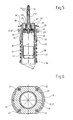
Mit 1 ist in Fig. 1 ein Presszylinder bezeichnet, in dessen in der Zeichnung unterseitigem
Boden 2 ein Kühlluftstutzen 3 angeordnet ist. Auf dem sich koaxial
zu dem Presszylinder 1 erstreckenden Kühlluftstutzen 3 ist ein Kolben 4 gleitfähig
geführt, innerhalb dessen hohl ausgebildeter Kolbenstange 5 sich der
Kühlluftstutzen 3 erstreckt. Die Kolbenstange 5 ist im Übrigen in einem Zwischenring
6 radial geführt, der zwischen einem Stempelzylinder 7 und einem
den oberen Abschluss des Presszylinders 1 bildenden Kopfring 8 axial eingespannt
ist. Der Stempelzylinder 7 erstreckt sich koaxial zu dem Presszylinder 1.1 with a press cylinder is referred to in the underside in the drawing
Floor 2 a
Das in der Zeichnung oberseitige Ende der Kolbenstange 5 steht in einer noch
näher zu erläuternden Weise mit einem Pressstempel 9 in Verbindung, der im
Übrigen innerhalb einer Ladebuchse 10 zentrisch geführt ist.The top side of the
Mit 11 ist eine an sich bekannte, längsgeteilte, einen Formhohlraum 12 umschließende
Vorform bezeichnet, die unterseitig ein ebenfalls längsgeteilt ausgebildetes
Mündungswerkzeug 13 umgibt, welches seinerseits einen ungeteilt
ausgebildeten Führungsring 14 umgibt. Das Mündungswerkzeug 13 ist in einem
wiederum längsgeteilt ausgebildeten Mündungswerkzeughalter 15 gehalten.
Das Gesamtsystem bestehend aus Mündungswerkzeughalter 15, Führungsring
14 und Mündungswerkzeug 13 ist koaxial mit der Achse 16 des Formhohlraums
12 ausgerichtet.11 is a per se known, longitudinally divided, a
In der in Fig. 1 gezeigten untersten oder Tiefststellung des Pressstempels 9
befindet sich die Ladebuchse 10 unterhalb einer Eingangsöffnung 13' des
Mündungswerkzeugs 13. In the lowest or lowest position of the
Ein Lagerring 17, innerhalb welchem die Ladebuchse 10 geführt ist, ist über
eine Zwischenscheibe 18 auf dem Stempelzylinder 7 abgestützt und in dieser
Position mittels eines Kopfringes 19 fixiert. Der Kopfring 19 wird seinerseits von
einem Abdeckring 20 überlagert, dessen Anlage an der zugekehrten Seite des
Kopfringes 19 mittels eines Sicherungsringes 21 gesichert ist.A
Wie insbesondere aus Fig. 6 hervorgeht, ist die Fixierung des Kopfringes 19
auf dem Stempelzylinder 7 durch Schrauben 22 gegeben, die in die äußere
Peripherie des Lagerringes 17 eingeformte, in etwa halbkreisförmige Ausnehmungen
23 durchdringen. Zwischen den Schrauben 22 und dem Lagerring 17
besteht stets ein radiales Spiel.As is apparent in particular from FIG. 6, the fixation of the
Wesentlich ist, das auch zwischen sämtlichen radialen Außenkonturen des Lagerringes
17 und den diesem zugekehrten radialen Innenkonturen des Kopfringes
19 sowie der Zwischenscheibe 18 ein radiales Spiel 24 besteht, dessen
Zweckbestimmung im Folgenden noch näher erläutert werden wird.It is essential that also between all radial outer contours of the
Fig. 6 zeigt dieses radiale Spiel 24 zwischen der Innenseite des Lagerringes 17
und der Außenseite eines an dem Lagerring angeformten Außenflansch 17',
über welchen dieser auf der zugekehrten Stirnseite der Zwischenscheibe 18
aufliegt. Die Innenkonturen des Kopfrings 19 bilden einen Lagerspalt 19' des
Stempelzylinders 7, innerhalb welchem der Lagerring 17 allseitig radial verschiebbar
ist.Fig. 6 shows this
Wie insbesondere Fig. 4 erkennen lässt, endet das oberseitige Ende der Kolbenstange
5 in einer sich koaxial zu dem Stempelzylinder 7 erstreckenden Gewindebohrung
25, in welche ein Kupplungskopf 26 eingeschraubt ist. In den
Kupplungskopf 26 ist eine Umfangsnut 27 eingeformt, die sich koaxial zu der
Achse 7' des Stempelzylinders 7 erstreckt und die mit einem sich radial innenseitig
erstreckenden Innenflansch 28 (Fig. 5) eines längsgeteilt ausgebildeten
Kupplungsringes 29, auch Splitring 29 genannt, im Eingriff steht. As can be seen in particular Fig. 4, ends the upper-side end of the
Wie insbesondere Fig. 5 erkennen lässt, weist der Splitring 29 eine global ringzylinderartige
Gestalt auf, an deren Unterseite der genannte Innenflansch 28
angeformt ist, wobei radial innenseitig eine Ringnut 30 vorgesehen ist, die ihrerseits
mit einem Flansch 31 des Pressstempels 9 im Eingriff steht.As can be seen in particular Fig. 5, the
Der Pressstempel 9 bildet an seinem, durch den Flansch 31 gekennzeichneten
Abschnitt ein zylindrisches Teil, welches der Aufnahme eines Halteringes 32
dient, der oberseitig über eine Feder 33, z.B. eine Tellerfeder, an dem
Pressstempel 9 abgestützt ist und dessen Position unterseitig durch einen Sicherungsring
34 definiert ist. Über den Flansch 31 ist der Pressstempel 7 in
dem geschlossenen Splitring 29 eingespannt. Der an dem Splitring 29 angeformte
Innenflansch 28 ist mit radialem Spiel in der Umfangsnut 27 des Kupplungskopfes
26 der Kolbenstange 5 aufgenommen.The press die 9 forms at its, characterized by the
Mit 35 ist ein Anschlagring bezeichnet, der die Ladebuchse 10 umgibt, und über
welchen der Lagerring 17 axial auf einem an der Ladebuchse 10 angeformten
Außenflansch 36 abgestützt ist. Das in allen Zeichnungsfiguren unterseitige
Ende der Ladebuchse 10 ist innerhalb einer Stützbuchse 37 aufgenommen,
wobei eine Rückstellfeder 38 an ihrem einen Ende auf einem an der Stützbuchse
37 angeformten Außenflansch 39 und an ihrem anderen Ende an der
dem Anschlagring 35 gegenüberliegenden Seite des Außenflansches 36 abgestützt
ist.With a
Der Haltering 32 ragt mit einem zentralen zylindrischen Ansatz 32' in den
Kupplungskopf 26 und damit in die Kolbenstange 5 hinein. Mittels der genannten
Feder 33 ist auf diesem Wege eine elastisch vorgespannte, dichtende Anlage
des Halterings 32 an einer äußersten Ringfläche des Kupplungskopfes 26
gegeben. Wesentlich ist, das der Ansatz 32' innerhalb des Kupplungskopfes 26
radial allseitig verschiebbar ist.The
Die Ladebuchse 10 bildet ferner an ihrem unterseitigen Ende einen sich radial
einwärts erstreckenden Innenflansch 40, auf welchem eine innerhalb der Ladebuchse
10 angeordnete Distanzbuchse 41 aufliegt. Die Funktion dieser
Distanzbuchse 41 wird im Folgenden noch erläutert werden. The charging
Die Stützbuchse 37 ist unten radial gleitbar auf dem Zwischenring 6 des Presszylinders
1 abgestützt.The
An der Stelle 42 in den Kühlluftstutzen 3 eintretende Kühlluft durchströmt diesen
sowie die Kolbenstange 5 in Richtung der Pfeile 43, um anschließend
durch den zentralen Hohlraum des Kupplungskopfes 26 hindurch in den einen
Hohlraum umschließenden Pressstempel 9 einzutreten. Zu diesem Zweck ist
innerhalb des Pressstempels 9 ein Kühlrohr 44 vorgesehen, welches sich mit
Abstand innerhalb des Pressstempels 9 erstreckt und mit Durchbrechungen 9'
(Fig. 5) versehen ist. Über diese Durchbrechungen 9' tritt die Kühlluft in einen
Zwischenraum 45 zwischen dem Kühlrohr 44 und der Innenwandung des
Pressstempels 9 aus, um diesen anschließend über Leitungselemente 46 (Fig.
5) und den Kupplungsring 29, einen Ringraum 47 zwischen der Kolbenstange 5
und der Distanzbuchse 41 und bodenseitige Ausnehmungen 48 der Stützbuchse
37 in Richtung von sich innerhalb der Wand des Presszylinders 1 erstreckenden
Längsbohrungen 49 in Richtung der Pfeile 50 zu verlassen. Der
Boden 2 des Presszylinders 1 beinhaltet somit Anschlussorgane für die Zufuhr
sowie die Abfuhr von Kühlluft.At the
Der Kolben 4 ist beidseitig beaufschlagbar. Mit 51 und 52 sind Anschlussöffnungen
für Druckluft bezeichnet, die nach Maßgabe der gewünschten Bewegungsrichtung
des Kolbens 4 mit Druckfluid beaufschlagt oder entlüftet werden.The
Der Presszylinder 1, der Kolben 4, sowie der Stempelzylinder 7 bilden eine,
durch ihre Achse 7' gekennzeichnete maschinenfeste Baugruppe, die erfindungsgemäß
an radialen Ausgleichsbewegungen zwecks Zentrierung gegenüber
der Vorform 11 nicht teilnimmt.The
Der Pressstempel 9, der Splitring 29, die Ladebuchse 10, der Lagerring 17, der
Anschlagring 35, die Distanzbuchse 41, die Stützbuchse 37 sowie die Rückstellfeder
38 bilden eine durch ihre Achse 10' gekennzeichnete Baugruppe, die
radial nach Maßgabe der konstruktiv vorgegebenen Spielabmessungen relativ
zu der Achse 16 der Vorform 11 justierbar ist. Ein Justieren in diesem Sinne
stellt sich somit praktisch als eine Parallelverschiebung der Achse 10' gegenüber
der Achse 7' dar, sowie als ein Ausrichten der Achsen 10' und 16.The
Die Wirkungsweise dieser vorstehend beschriebenen Vorformstation gestaltet sich wie folgt:The operation of this preform station described above designed itself as follows:
In der in Fig. 1 gezeigten Tiefststellung des Pressstempels 9 ist dieser über den
Splitring 29 und den Kupplungskopf 26 auf der Kolbenstange 5 gehalten. Der
Splitring 29 ist seinerseits über die Distanzbuchse 41, die Ladebuchse 10 und
die Stützbuchse 37 auf dem Zwischenring 6 und damit dem Kopfring 8 des
Presszylinders 1 abgestützt. Die Oberkante der Ladebuchse 10 befindet sich
unterhalb der zugekehrten Eingangsöffnung 13' des Mündungswerkzeugs 13.In the lowest position of the
Die Rückstellfeder 38 steht in dieser Betriebsphase unter elastischer Druckvorspannung
und hält die Ladebuchse 10 über ihren Ringflansch 36 in Anlage an
dem Anschlagring 35. Diese Position ist durch Beaufschlagung der Oberseite
des Kolbens 4 gesichert.The
Zur Überführung in die in Fig. 2 gezeigte Ladestellung wird die Oberseite des
Kolbens 4 entlüftet, so dass sich die Kolbenstange 5 unter der Wirkung der
Rückstellfeder 38 in die in Fig. 2 gezeigte Position bewegt. Die Ladestellung ist
dadurch gekennzeichnet, dass infolge einer Aufwärtsbewegung der Kolbenstange
5 in Richtung des Pfeiles 53 die sich entspannende Rückstellfeder 38
über den Ringflansch 36 eine Mitnahmewirkung auf die Ladebuchse 10 ausübt,
und zwar bis der Anschlagring 35 an der zugekehrten Kreisringfläche 17" des
Lagerrings 17 anliegt. Der Anschlagring 35 begrenzt somit die Aufwärtsbewegung
der Ladebuchse 10, welche in der Ladestellung um ein definiertes Maß
in das Mündungswerkzeug 13 eingeführt worden ist. Infolge dieses Einführens
in das Mündungswerkzeug sind die Ladebuchse 10 und mit dieser auch der
Pressstempel 9 zentriert, und zwar bezüglich der Achse 16 des Formhohlraums
12.For the transfer to the loading position shown in Fig. 2, the top of the
Die Ladebuchse 10 ist mit ihrem freien, mit einer Fase 10" versehenen Ende
mit einer radialen Gleitpassung in das geschlossene Mündungswerkzeug 13
einführbar. Ein eventueller Fluchtungsfehler zwischen den Achsen der Ladebuchse
10 bzw. des Pressstempels 9 relativ zu der Achse 16 ist dadurch ausgleichbar,
dass, wie insbesondere in Fig. 6 gezeigt, ein radiales Spiel zwischen
der Außenseite des Außenflansches 17' des Lagerrings 17 und der Innenseite
des Kopfrings 19 besteht, welches nach Maßgabe dieses Spieles ein radiales
Versetzen der Ladebuchse 10 relativ zu der Achse 7' des Stempelzylinders 7
ermöglicht.The charging
Ein radiales Spiel besteht ferner zwischen den radialen Außenseiten des
Außenflansches 39 und des Anschlagringes 35 relativ zu der radialen Innenseite
des Stempelzylinders 7. Man erkennt, dass die Baugruppe, die im Wesentlichen
aus dem Pressstempel 9, dem Lagerring 17, dem Anschlagring 35,
der Ladebuchse 10 sowie der Stützbuchse 37 besteht, radial einstellbar ist, und
zwar nach Maßgabe der eingangs erwähnten radialen Freiräume.A radial clearance further exists between the radial outer sides of the
Man erkennt ferner, dass zum Zentrieren dieser Baugruppe relativ zu der
Achse 16 des Formhohlraumes 12 nur vergleichsweise geringe Massen bewegt
werden müssen, wobei der Einstellvorgang auch vergleichsweise leichtgängig
abgewickelt werden kann, da entgegenstehende Reibungskräfte erzeugende
Anpresskräfte in dieser Phase noch vergleichsweise gering ausfallen, so dass
ein dementsprechend geringer Verschleiß erwartet werden kann.It can also be seen that for centering this assembly relative to the
Nachdem zwischen den radialen Abmessungen des Innenflansches 28 und der
Ringnut 27 ebenfalls ein radiales Spiel besteht, wird die Kolbenstange 5 von
diesen radialen Ausgleichsbewegungen nicht erfasst.After between the radial dimensions of the
Ausgehend von der durch eine zentrierte Position bezüglich der Achse 16 des
Formhohlraums 12 gekennzeichneten Ladestellung wird nunmehr durch Druckbeaufschlagung
der Unterseite des Kolbens 4 der Pressstempel 9 in den
Formhohlraum 12 eingeführt, der zuvor geschlossen und mit einem Glasposten
beschickt worden ist. Die obere Endstellung des Pressstempels 9 ist erreicht,
sobald der Formhohlraum 12 vollständig mit schmelzflüssigem Glas gefüllt und
ein Külbel fertiggestellt ist. Starting from the centered position with respect to the
Ein Zurückfahren des Pressstempels 9 kann durch Druckbeaufschlagung der
Oberseite des Kolbens 4 über die Anschlussöffnung 52 erfolgen, woraufhin der
Kolben 4 wieder in seine in Fig. 1 wiedergegebene Tiefststellung überführt wird,
in welcher der Pressstempel 9 wiederum über den Distanzring 41, die
Ladebuchse 10 und die Stützbuchse 37 auf dem Zwischenring 6 und damit
dem Presszylinder 1 abgestützt ist.A retraction of the
Von besonderem Vorteil ist, dass jeder Pressstempel 9 nebst Ladebuchse 10
individuell zentriert werden kann, so dass Fluchtungsfehlern des einzelnen
Pressstempels bzw. des Formwerkzeugs optimal Rechnung getragen werden
kann.Of particular advantage is that each
Claims (10)
und wobei die Ladebuchse (10) bei Bewegung der Kolbenstange (5) in der entgegengesetzten Richtung durch die Rückstellfeder (38) bis in eine Arbeitsstellung in Anlage an dem Stempelzylinder (7) bewegbar ist,
dadurch gekennzeichnet, dass eine im Wesentlichen den Presszylinder (1), den Kolben (4), die Kolbenstange (5) und den Stempelzylinder (7) umfassende erste, eine Längsachse (7') aufweisende Baueinheit maschinenfest angeordnet ist,
dass zur Ausrichtung des Pressstempels (9) relativ zu der Achse (16) des Mündungswerkzeugs (13) sowie der Vorform (11) eine zweite Baueinheit quer zu der Längsachse (7') der ersten Baueinheit und relativ zu der ersten Baueinheit bewegbar ist, wobei die zweite Baueinheit im Wesentlichen den Splitring (29), den Pressstempel (9), die Ladebuchse (10) und die Rückstellfeder (38) aufweist und
dass die zweite Baueinheit gegenüber der ersten Baueinheit infolge eines Überführens der Ladebuchse (10) ausgehend von der genannten Ausgangsstellung, in der sie nicht mit dem Mündungswerkzeug (13) im Eingriff steht, in das Mündungswerkzeug (13) hinein ausrichtbar ist.A preforming station of a press-blown glass forming machine having a preform (11) having an axis (16), a longitudinally split mouth tool (13) reciprocable between the preform station and a preforming station of the press-blown glass forming machine and a ram mechanism, wherein the Crimping mechanism has:
and wherein the charging socket (10) is movable in the opposite direction by the return spring (38) when the piston rod (5) moves into a working position in contact with the stamp cylinder (7),
characterized in that a first assembly, comprising essentially the pressing cylinder (1), the piston (4), the piston rod (5) and the stamp cylinder (7), has a machine axis fixed to a longitudinal axis (7 '),
in that, in order to align the press ram (9) relative to the axis (16) of the necking tool (13) and the preform (11), a second structural unit is movable transversely to the longitudinal axis (7 ') of the first structural unit and relative to the first structural unit the second structural unit essentially comprises the split ring (29), the press ram (9), the charging socket (10) and the return spring (38), and
that the second structural unit with respect to the first structural unit due to a transfer of the charging socket (10) starting from said initial position in which it is not engaged with the necking tool (13) into the necking tool (13) into aligned.
Applications Claiming Priority (2)
| Application Number | Priority Date | Filing Date | Title |
|---|---|---|---|
| DE200420003097 DE202004003097U1 (en) | 2004-02-28 | 2004-02-28 | Preforming station of a press-blow glass molding machine |
| DE202004003097U | 2004-02-28 |
Publications (3)
| Publication Number | Publication Date |
|---|---|
| EP1568663A2 true EP1568663A2 (en) | 2005-08-31 |
| EP1568663A3 EP1568663A3 (en) | 2006-07-26 |
| EP1568663B1 EP1568663B1 (en) | 2012-08-15 |
Family
ID=32240912
Family Applications (1)
| Application Number | Title | Priority Date | Filing Date |
|---|---|---|---|
| EP20040027162 Expired - Lifetime EP1568663B1 (en) | 2004-02-28 | 2004-11-16 | Preform station of a press-blow machine |
Country Status (2)
| Country | Link |
|---|---|
| EP (1) | EP1568663B1 (en) |
| DE (1) | DE202004003097U1 (en) |
Families Citing this family (3)
| Publication number | Priority date | Publication date | Assignee | Title |
|---|---|---|---|---|
| DE102005001065A1 (en) * | 2005-01-07 | 2006-07-20 | Gps Glasproduktions-Service Gmbh | Preform or finished shape of a glass machine |
| DE102014011310B4 (en) | 2014-08-04 | 2021-04-15 | Heye International Gmbh | Method and device for improving the safety of the operation of a glass forming machine |
| DE102017123216A1 (en) | 2016-10-07 | 2018-04-12 | Manuel Ecker | Mold and press die for a glass forming machine with 3D printed cooling channels |
Citations (2)
| Publication number | Priority date | Publication date | Assignee | Title |
|---|---|---|---|---|
| GB1288477A (en) | 1969-08-19 | 1972-09-13 | ||
| DE3638677A1 (en) | 1986-11-12 | 1988-05-26 | Heye Hermann Fa | Device for guiding a press plunger of an individual section glass moulding machine |
Family Cites Families (3)
| Publication number | Priority date | Publication date | Assignee | Title |
|---|---|---|---|---|
| JPH11209129A (en) * | 1998-01-26 | 1999-08-03 | Nihon Yamamura Glass Co Ltd | Formation of hollow container and its device |
| US6286339B1 (en) * | 2000-01-28 | 2001-09-11 | Owens-Brockway Glass Container Inc. | Glass container forming machine plunger assembly |
| US7073352B2 (en) * | 2002-03-07 | 2006-07-11 | Vitro Global, S.A. | Method and a machine for the production of hollow glassware articles |
-
2004
- 2004-02-28 DE DE200420003097 patent/DE202004003097U1/en not_active Expired - Lifetime
- 2004-11-16 EP EP20040027162 patent/EP1568663B1/en not_active Expired - Lifetime
Patent Citations (2)
| Publication number | Priority date | Publication date | Assignee | Title |
|---|---|---|---|---|
| GB1288477A (en) | 1969-08-19 | 1972-09-13 | ||
| DE3638677A1 (en) | 1986-11-12 | 1988-05-26 | Heye Hermann Fa | Device for guiding a press plunger of an individual section glass moulding machine |
Also Published As
| Publication number | Publication date |
|---|---|
| EP1568663A3 (en) | 2006-07-26 |
| EP1568663B1 (en) | 2012-08-15 |
| DE202004003097U1 (en) | 2004-04-29 |
Similar Documents
| Publication | Publication Date | Title |
|---|---|---|
| EP0125488B1 (en) | Cooling device for a shaping tool for working glass or thermo-plastic material | |
| DE2503458A1 (en) | TOGGLE PRESS | |
| DE2415549B2 (en) | Device for the non-cutting cold forming of a blank | |
| DE10123745C2 (en) | Hydraulic-mechanical locking device, preferably for cross extrusion | |
| DE60216750T2 (en) | DOUBLE-ACTING FLOOR FORMAT FOR HIGH-ACTIVITY OPERATION | |
| DE2224592A1 (en) | Double-acting single-piston press i for compressing powder | |
| DE19962607B4 (en) | Tool cassette with resilient die | |
| EP3347161A1 (en) | Actuating device for a steady rest | |
| DE3805374A1 (en) | DEVICE FOR DEFORMING THE BOTTOM OF A CAN BODY | |
| EP0849011B1 (en) | Method of and installation for manufacturing hollow profiles with end cross-section extensions | |
| EP0106182A1 (en) | Press to crimp sleeves, cable terminations and the like | |
| DE2112651B2 (en) | Clamping and releasing device for tools on drilling, milling and similar machine tools | |
| EP1568663A2 (en) | Preform station of a press-blow machine | |
| DE2152641A1 (en) | Damping device for a hydraulic pressure piston | |
| DE29824688U1 (en) | radial press | |
| DE2517640C3 (en) | Guide for a piston by means of a bush | |
| EP0002032B1 (en) | Method and apparatus for making multiple-groove pulleys | |
| DE19511447C2 (en) | Device for shaping the end area of a pipe for use in screw connections | |
| EP1073556B1 (en) | Radial press | |
| DE1452547A1 (en) | Device for making a branched pipe connection | |
| DE602004005701T2 (en) | PRESSURE DISTRIBUTOR WITH DOUBLE GUIDANCE | |
| DE2460344A1 (en) | Manually operated hydraulic pressure valve - has supply conduit system blocked via compressible sealing lip | |
| DE2953354C2 (en) | Method for producing an inner joint body for a constant velocity joint | |
| DE10030792C2 (en) | Multi-stage press, in particular cross transport press, with hydraulic closing device | |
| DE1223257B (en) | Pneumatic three-position working cylinder |
Legal Events
| Date | Code | Title | Description |
|---|---|---|---|
| PUAI | Public reference made under article 153(3) epc to a published international application that has entered the european phase |
Free format text: ORIGINAL CODE: 0009012 |
|
| AK | Designated contracting states |
Kind code of ref document: A2 Designated state(s): AT BE BG CH CY CZ DE DK EE ES FI FR GB GR HU IE IS IT LI LU MC NL PL PT RO SE SI SK TR |
|
| AX | Request for extension of the european patent |
Extension state: AL HR LT LV MK YU |
|
| PUAL | Search report despatched |
Free format text: ORIGINAL CODE: 0009013 |
|
| AK | Designated contracting states |
Kind code of ref document: A3 Designated state(s): AT BE BG CH CY CZ DE DK EE ES FI FR GB GR HU IE IS IT LI LU MC NL PL PT RO SE SI SK TR |
|
| AX | Request for extension of the european patent |
Extension state: AL HR LT LV MK YU |
|
| 17P | Request for examination filed |
Effective date: 20061202 |
|
| AKX | Designation fees paid |
Designated state(s): AT BE BG CH CY CZ DE DK EE ES FI FR GB GR HU IE IS IT LI LU MC NL PL PT RO SE SI SK TR |
|
| 17Q | First examination report despatched |
Effective date: 20070418 |
|
| GRAP | Despatch of communication of intention to grant a patent |
Free format text: ORIGINAL CODE: EPIDOSNIGR1 |
|
| GRAS | Grant fee paid |
Free format text: ORIGINAL CODE: EPIDOSNIGR3 |
|
| GRAA | (expected) grant |
Free format text: ORIGINAL CODE: 0009210 |
|
| AK | Designated contracting states |
Kind code of ref document: B1 Designated state(s): AT BE BG CH CY CZ DE DK EE ES FI FR GB GR HU IE IS IT LI LU MC NL PL PT RO SE SI SK TR |
|
| REG | Reference to a national code |
Ref country code: CH Ref legal event code: EP Ref country code: GB Ref legal event code: FG4D Free format text: NOT ENGLISH Ref country code: AT Ref legal event code: REF Ref document number: 570719 Country of ref document: AT Kind code of ref document: T Effective date: 20120815 |
|
| REG | Reference to a national code |
Ref country code: DE Ref legal event code: R082 Ref document number: 502004013692 Country of ref document: DE Representative=s name: SOBISCH & KRAMM, DE |
|
| REG | Reference to a national code |
Ref country code: CH Ref legal event code: NV Representative=s name: BOHEST AG |
|
| REG | Reference to a national code |
Ref country code: IE Ref legal event code: FG4D Free format text: LANGUAGE OF EP DOCUMENT: GERMAN |
|
| REG | Reference to a national code |
Ref country code: SE Ref legal event code: TRGR |
|
| REG | Reference to a national code |
Ref country code: DE Ref legal event code: R096 Ref document number: 502004013692 Country of ref document: DE Effective date: 20121018 |
|
| REG | Reference to a national code |
Ref country code: NL Ref legal event code: VDEP Effective date: 20120815 |
|
| PG25 | Lapsed in a contracting state [announced via postgrant information from national office to epo] |
Ref country code: FI Free format text: LAPSE BECAUSE OF FAILURE TO SUBMIT A TRANSLATION OF THE DESCRIPTION OR TO PAY THE FEE WITHIN THE PRESCRIBED TIME-LIMIT Effective date: 20120815 Ref country code: CY Free format text: LAPSE BECAUSE OF FAILURE TO SUBMIT A TRANSLATION OF THE DESCRIPTION OR TO PAY THE FEE WITHIN THE PRESCRIBED TIME-LIMIT Effective date: 20120815 Ref country code: IS Free format text: LAPSE BECAUSE OF FAILURE TO SUBMIT A TRANSLATION OF THE DESCRIPTION OR TO PAY THE FEE WITHIN THE PRESCRIBED TIME-LIMIT Effective date: 20121215 |
|
| PG25 | Lapsed in a contracting state [announced via postgrant information from national office to epo] |
Ref country code: PT Free format text: LAPSE BECAUSE OF FAILURE TO SUBMIT A TRANSLATION OF THE DESCRIPTION OR TO PAY THE FEE WITHIN THE PRESCRIBED TIME-LIMIT Effective date: 20121217 Ref country code: GR Free format text: LAPSE BECAUSE OF FAILURE TO SUBMIT A TRANSLATION OF THE DESCRIPTION OR TO PAY THE FEE WITHIN THE PRESCRIBED TIME-LIMIT Effective date: 20121116 Ref country code: SI Free format text: LAPSE BECAUSE OF FAILURE TO SUBMIT A TRANSLATION OF THE DESCRIPTION OR TO PAY THE FEE WITHIN THE PRESCRIBED TIME-LIMIT Effective date: 20120815 Ref country code: PL Free format text: LAPSE BECAUSE OF FAILURE TO SUBMIT A TRANSLATION OF THE DESCRIPTION OR TO PAY THE FEE WITHIN THE PRESCRIBED TIME-LIMIT Effective date: 20120815 |
|
| PG25 | Lapsed in a contracting state [announced via postgrant information from national office to epo] |
Ref country code: NL Free format text: LAPSE BECAUSE OF FAILURE TO SUBMIT A TRANSLATION OF THE DESCRIPTION OR TO PAY THE FEE WITHIN THE PRESCRIBED TIME-LIMIT Effective date: 20120815 |
|
| PG25 | Lapsed in a contracting state [announced via postgrant information from national office to epo] |
Ref country code: DK Free format text: LAPSE BECAUSE OF FAILURE TO SUBMIT A TRANSLATION OF THE DESCRIPTION OR TO PAY THE FEE WITHIN THE PRESCRIBED TIME-LIMIT Effective date: 20120815 Ref country code: RO Free format text: LAPSE BECAUSE OF FAILURE TO SUBMIT A TRANSLATION OF THE DESCRIPTION OR TO PAY THE FEE WITHIN THE PRESCRIBED TIME-LIMIT Effective date: 20120815 Ref country code: ES Free format text: LAPSE BECAUSE OF FAILURE TO SUBMIT A TRANSLATION OF THE DESCRIPTION OR TO PAY THE FEE WITHIN THE PRESCRIBED TIME-LIMIT Effective date: 20121126 Ref country code: EE Free format text: LAPSE BECAUSE OF FAILURE TO SUBMIT A TRANSLATION OF THE DESCRIPTION OR TO PAY THE FEE WITHIN THE PRESCRIBED TIME-LIMIT Effective date: 20120815 |
|
| BERE | Be: lapsed |
Owner name: HEYE INTERNATIONAL G.M.B.H. Effective date: 20121130 |
|
| PG25 | Lapsed in a contracting state [announced via postgrant information from national office to epo] |
Ref country code: SK Free format text: LAPSE BECAUSE OF FAILURE TO SUBMIT A TRANSLATION OF THE DESCRIPTION OR TO PAY THE FEE WITHIN THE PRESCRIBED TIME-LIMIT Effective date: 20120815 |
|
| PLBE | No opposition filed within time limit |
Free format text: ORIGINAL CODE: 0009261 |
|
| STAA | Information on the status of an ep patent application or granted ep patent |
Free format text: STATUS: NO OPPOSITION FILED WITHIN TIME LIMIT |
|
| 26N | No opposition filed |
Effective date: 20130516 |
|
| PG25 | Lapsed in a contracting state [announced via postgrant information from national office to epo] |
Ref country code: BG Free format text: LAPSE BECAUSE OF FAILURE TO SUBMIT A TRANSLATION OF THE DESCRIPTION OR TO PAY THE FEE WITHIN THE PRESCRIBED TIME-LIMIT Effective date: 20121115 |
|
| REG | Reference to a national code |
Ref country code: IE Ref legal event code: MM4A |
|
| PG25 | Lapsed in a contracting state [announced via postgrant information from national office to epo] |
Ref country code: BE Free format text: LAPSE BECAUSE OF NON-PAYMENT OF DUE FEES Effective date: 20121130 |
|
| REG | Reference to a national code |
Ref country code: DE Ref legal event code: R097 Ref document number: 502004013692 Country of ref document: DE Effective date: 20130516 |
|
| PG25 | Lapsed in a contracting state [announced via postgrant information from national office to epo] |
Ref country code: IE Free format text: LAPSE BECAUSE OF NON-PAYMENT OF DUE FEES Effective date: 20121116 |
|
| REG | Reference to a national code |
Ref country code: AT Ref legal event code: MM01 Ref document number: 570719 Country of ref document: AT Kind code of ref document: T Effective date: 20121130 |
|
| PG25 | Lapsed in a contracting state [announced via postgrant information from national office to epo] |
Ref country code: AT Free format text: LAPSE BECAUSE OF NON-PAYMENT OF DUE FEES Effective date: 20121130 |
|
| PGFP | Annual fee paid to national office [announced via postgrant information from national office to epo] |
Ref country code: CH Payment date: 20131122 Year of fee payment: 10 Ref country code: SE Payment date: 20131122 Year of fee payment: 10 Ref country code: CZ Payment date: 20131106 Year of fee payment: 10 Ref country code: FR Payment date: 20131119 Year of fee payment: 10 |
|
| PGFP | Annual fee paid to national office [announced via postgrant information from national office to epo] |
Ref country code: IT Payment date: 20131126 Year of fee payment: 10 |
|
| PG25 | Lapsed in a contracting state [announced via postgrant information from national office to epo] |
Ref country code: MC Free format text: LAPSE BECAUSE OF NON-PAYMENT OF DUE FEES Effective date: 20121130 Ref country code: TR Free format text: LAPSE BECAUSE OF FAILURE TO SUBMIT A TRANSLATION OF THE DESCRIPTION OR TO PAY THE FEE WITHIN THE PRESCRIBED TIME-LIMIT Effective date: 20120815 |
|
| PG25 | Lapsed in a contracting state [announced via postgrant information from national office to epo] |
Ref country code: LU Free format text: LAPSE BECAUSE OF NON-PAYMENT OF DUE FEES Effective date: 20121116 |
|
| PG25 | Lapsed in a contracting state [announced via postgrant information from national office to epo] |
Ref country code: HU Free format text: LAPSE BECAUSE OF FAILURE TO SUBMIT A TRANSLATION OF THE DESCRIPTION OR TO PAY THE FEE WITHIN THE PRESCRIBED TIME-LIMIT Effective date: 20041116 |
|
| REG | Reference to a national code |
Ref country code: CH Ref legal event code: PCAR Free format text: NEW ADDRESS: HOLBEINSTRASSE 36-38, 4051 BASEL (CH) |
|
| REG | Reference to a national code |
Ref country code: SE Ref legal event code: EUG Ref country code: CH Ref legal event code: PL |
|
| PG25 | Lapsed in a contracting state [announced via postgrant information from national office to epo] |
Ref country code: LI Free format text: LAPSE BECAUSE OF NON-PAYMENT OF DUE FEES Effective date: 20141130 Ref country code: SE Free format text: LAPSE BECAUSE OF NON-PAYMENT OF DUE FEES Effective date: 20141117 Ref country code: CH Free format text: LAPSE BECAUSE OF NON-PAYMENT OF DUE FEES Effective date: 20141130 Ref country code: CZ Free format text: LAPSE BECAUSE OF NON-PAYMENT OF DUE FEES Effective date: 20141116 |
|
| REG | Reference to a national code |
Ref country code: FR Ref legal event code: ST Effective date: 20150731 |
|
| PG25 | Lapsed in a contracting state [announced via postgrant information from national office to epo] |
Ref country code: FR Free format text: LAPSE BECAUSE OF NON-PAYMENT OF DUE FEES Effective date: 20141201 |
|
| PG25 | Lapsed in a contracting state [announced via postgrant information from national office to epo] |
Ref country code: IT Free format text: LAPSE BECAUSE OF NON-PAYMENT OF DUE FEES Effective date: 20141116 |
|
| PGFP | Annual fee paid to national office [announced via postgrant information from national office to epo] |
Ref country code: GB Payment date: 20151123 Year of fee payment: 12 |
|
| GBPC | Gb: european patent ceased through non-payment of renewal fee |
Effective date: 20161116 |
|
| PG25 | Lapsed in a contracting state [announced via postgrant information from national office to epo] |
Ref country code: GB Free format text: LAPSE BECAUSE OF NON-PAYMENT OF DUE FEES Effective date: 20161116 |
|
| PGFP | Annual fee paid to national office [announced via postgrant information from national office to epo] |
Ref country code: DE Payment date: 20181205 Year of fee payment: 15 |
|
| REG | Reference to a national code |
Ref country code: DE Ref legal event code: R119 Ref document number: 502004013692 Country of ref document: DE |
|
| PG25 | Lapsed in a contracting state [announced via postgrant information from national office to epo] |
Ref country code: DE Free format text: LAPSE BECAUSE OF NON-PAYMENT OF DUE FEES Effective date: 20200603 |