EP1568524A1 - Air conditioner - Google Patents
Air conditioner Download PDFInfo
- Publication number
- EP1568524A1 EP1568524A1 EP03777181A EP03777181A EP1568524A1 EP 1568524 A1 EP1568524 A1 EP 1568524A1 EP 03777181 A EP03777181 A EP 03777181A EP 03777181 A EP03777181 A EP 03777181A EP 1568524 A1 EP1568524 A1 EP 1568524A1
- Authority
- EP
- European Patent Office
- Prior art keywords
- refrigerant
- cooling water
- heat exchanger
- water
- air conditioner
- Prior art date
- Legal status (The legal status is an assumption and is not a legal conclusion. Google has not performed a legal analysis and makes no representation as to the accuracy of the status listed.)
- Withdrawn
Links
Images


Classifications
-
- B—PERFORMING OPERATIONS; TRANSPORTING
- B60—VEHICLES IN GENERAL
- B60H—ARRANGEMENTS OF HEATING, COOLING, VENTILATING OR OTHER AIR-TREATING DEVICES SPECIALLY ADAPTED FOR PASSENGER OR GOODS SPACES OF VEHICLES
- B60H1/00—Heating, cooling or ventilating devices
- B60H1/00357—Air-conditioning arrangements specially adapted for particular vehicles
- B60H1/00385—Air-conditioning arrangements specially adapted for particular vehicles for vehicles having an electrical drive, e.g. hybrid or fuel cell
- B60H1/004—Air-conditioning arrangements specially adapted for particular vehicles for vehicles having an electrical drive, e.g. hybrid or fuel cell for vehicles having a combustion engine and electric drive means, e.g. hybrid electric vehicles
-
- B—PERFORMING OPERATIONS; TRANSPORTING
- B60—VEHICLES IN GENERAL
- B60H—ARRANGEMENTS OF HEATING, COOLING, VENTILATING OR OTHER AIR-TREATING DEVICES SPECIALLY ADAPTED FOR PASSENGER OR GOODS SPACES OF VEHICLES
- B60H1/00—Heating, cooling or ventilating devices
- B60H1/00642—Control systems or circuits; Control members or indication devices for heating, cooling or ventilating devices
- B60H1/00814—Control systems or circuits characterised by their output, for controlling particular components of the heating, cooling or ventilating installation
- B60H1/00878—Control systems or circuits characterised by their output, for controlling particular components of the heating, cooling or ventilating installation the components being temperature regulating devices
- B60H1/00885—Controlling the flow of heating or cooling liquid, e.g. valves or pumps
-
- B—PERFORMING OPERATIONS; TRANSPORTING
- B60—VEHICLES IN GENERAL
- B60H—ARRANGEMENTS OF HEATING, COOLING, VENTILATING OR OTHER AIR-TREATING DEVICES SPECIALLY ADAPTED FOR PASSENGER OR GOODS SPACES OF VEHICLES
- B60H1/00—Heating, cooling or ventilating devices
- B60H1/00642—Control systems or circuits; Control members or indication devices for heating, cooling or ventilating devices
- B60H1/00814—Control systems or circuits characterised by their output, for controlling particular components of the heating, cooling or ventilating installation
- B60H1/00878—Control systems or circuits characterised by their output, for controlling particular components of the heating, cooling or ventilating installation the components being temperature regulating devices
- B60H1/00899—Controlling the flow of liquid in a heat pump system
-
- F—MECHANICAL ENGINEERING; LIGHTING; HEATING; WEAPONS; BLASTING
- F25—REFRIGERATION OR COOLING; COMBINED HEATING AND REFRIGERATION SYSTEMS; HEAT PUMP SYSTEMS; MANUFACTURE OR STORAGE OF ICE; LIQUEFACTION SOLIDIFICATION OF GASES
- F25B—REFRIGERATION MACHINES, PLANTS OR SYSTEMS; COMBINED HEATING AND REFRIGERATION SYSTEMS; HEAT PUMP SYSTEMS
- F25B41/00—Fluid-circulation arrangements
- F25B41/30—Expansion means; Dispositions thereof
- F25B41/39—Dispositions with two or more expansion means arranged in series, i.e. multi-stage expansion, on a refrigerant line leading to the same evaporator
-
- F—MECHANICAL ENGINEERING; LIGHTING; HEATING; WEAPONS; BLASTING
- F25—REFRIGERATION OR COOLING; COMBINED HEATING AND REFRIGERATION SYSTEMS; HEAT PUMP SYSTEMS; MANUFACTURE OR STORAGE OF ICE; LIQUEFACTION SOLIDIFICATION OF GASES
- F25B—REFRIGERATION MACHINES, PLANTS OR SYSTEMS; COMBINED HEATING AND REFRIGERATION SYSTEMS; HEAT PUMP SYSTEMS
- F25B9/00—Compression machines, plants or systems, in which the refrigerant is air or other gas of low boiling point
- F25B9/002—Compression machines, plants or systems, in which the refrigerant is air or other gas of low boiling point characterised by the refrigerant
- F25B9/008—Compression machines, plants or systems, in which the refrigerant is air or other gas of low boiling point characterised by the refrigerant the refrigerant being carbon dioxide
-
- B—PERFORMING OPERATIONS; TRANSPORTING
- B60—VEHICLES IN GENERAL
- B60H—ARRANGEMENTS OF HEATING, COOLING, VENTILATING OR OTHER AIR-TREATING DEVICES SPECIALLY ADAPTED FOR PASSENGER OR GOODS SPACES OF VEHICLES
- B60H1/00—Heating, cooling or ventilating devices
- B60H1/00642—Control systems or circuits; Control members or indication devices for heating, cooling or ventilating devices
- B60H1/00814—Control systems or circuits characterised by their output, for controlling particular components of the heating, cooling or ventilating installation
- B60H1/00878—Control systems or circuits characterised by their output, for controlling particular components of the heating, cooling or ventilating installation the components being temperature regulating devices
- B60H2001/00928—Control systems or circuits characterised by their output, for controlling particular components of the heating, cooling or ventilating installation the components being temperature regulating devices comprising a secondary circuit
-
- B—PERFORMING OPERATIONS; TRANSPORTING
- B60—VEHICLES IN GENERAL
- B60H—ARRANGEMENTS OF HEATING, COOLING, VENTILATING OR OTHER AIR-TREATING DEVICES SPECIALLY ADAPTED FOR PASSENGER OR GOODS SPACES OF VEHICLES
- B60H1/00—Heating, cooling or ventilating devices
- B60H1/00642—Control systems or circuits; Control members or indication devices for heating, cooling or ventilating devices
- B60H1/00814—Control systems or circuits characterised by their output, for controlling particular components of the heating, cooling or ventilating installation
- B60H1/00878—Control systems or circuits characterised by their output, for controlling particular components of the heating, cooling or ventilating installation the components being temperature regulating devices
- B60H2001/00961—Control systems or circuits characterised by their output, for controlling particular components of the heating, cooling or ventilating installation the components being temperature regulating devices comprising means for defrosting outside heat exchangers
-
- F—MECHANICAL ENGINEERING; LIGHTING; HEATING; WEAPONS; BLASTING
- F25—REFRIGERATION OR COOLING; COMBINED HEATING AND REFRIGERATION SYSTEMS; HEAT PUMP SYSTEMS; MANUFACTURE OR STORAGE OF ICE; LIQUEFACTION SOLIDIFICATION OF GASES
- F25B—REFRIGERATION MACHINES, PLANTS OR SYSTEMS; COMBINED HEATING AND REFRIGERATION SYSTEMS; HEAT PUMP SYSTEMS
- F25B2309/00—Gas cycle refrigeration machines
- F25B2309/06—Compression machines, plants or systems characterised by the refrigerant being carbon dioxide
- F25B2309/061—Compression machines, plants or systems characterised by the refrigerant being carbon dioxide with cycle highest pressure above the supercritical pressure
-
- F—MECHANICAL ENGINEERING; LIGHTING; HEATING; WEAPONS; BLASTING
- F25—REFRIGERATION OR COOLING; COMBINED HEATING AND REFRIGERATION SYSTEMS; HEAT PUMP SYSTEMS; MANUFACTURE OR STORAGE OF ICE; LIQUEFACTION SOLIDIFICATION OF GASES
- F25B—REFRIGERATION MACHINES, PLANTS OR SYSTEMS; COMBINED HEATING AND REFRIGERATION SYSTEMS; HEAT PUMP SYSTEMS
- F25B2339/00—Details of evaporators; Details of condensers
- F25B2339/04—Details of condensers
- F25B2339/047—Water-cooled condensers
-
- F—MECHANICAL ENGINEERING; LIGHTING; HEATING; WEAPONS; BLASTING
- F25—REFRIGERATION OR COOLING; COMBINED HEATING AND REFRIGERATION SYSTEMS; HEAT PUMP SYSTEMS; MANUFACTURE OR STORAGE OF ICE; LIQUEFACTION SOLIDIFICATION OF GASES
- F25B—REFRIGERATION MACHINES, PLANTS OR SYSTEMS; COMBINED HEATING AND REFRIGERATION SYSTEMS; HEAT PUMP SYSTEMS
- F25B6/00—Compression machines, plants or systems, with several condenser circuits
- F25B6/04—Compression machines, plants or systems, with several condenser circuits arranged in series
Definitions
- the present invention relates to an air conditioner and an air conditioning method.
- the hybrid electric vehicle equipped with the engine for driving assist runs on a vehicle drive motor during urban driving and on the engine if a remaining battery level is low or during suburban driving.
- the hybrid electric vehicle equipped with the engine for power generation runs on a vehicle drive motor and starts an engine to charge the battery if a remaining battery level becomes low.
- An air conditioner for a present electric vehicle generally drives a compressor (open type) of a refrigerant cycle on a vehicle drive motor.
- an air conditioner for the above-mentioned hybrid electric vehicle may cool a vehicle compartment inside by driving a compressor on an engine when the engine is in a drive condition. It may cool the vehicle compartment, when the engine is stopping, by driving the compressor using the vehicle drive motor, and, when a remaining battery level is low during the engine stopping, by starting the engine to drive the compressor.
- a conventional air conditioner is structured so that a vehicle compartment inside may be heated by simply sending air to a heater core supplied with engine cooling water during heating operation, therefore when a temperature of cooling water is low, for example, at engine start-up, long time was required until an air-conditioning temperature in the vehicle compartment inside reaches a target temperature.
- a temperature of cooling water is low, for example, at engine start-up, long time was required until an air-conditioning temperature in the vehicle compartment inside reaches a target temperature.
- a PTC heater As an auxiliary heating means.
- Recent engines of other vehicle as well as the hybrid electric vehicle have been highly advanced and heat radiation from the engine has decreased; therefore the engine cooling water was heated with the PTC heater as an auxiliary heating means. Because an electric heater such as the PTC heater was used as an auxiliary heatingmeans, heating efficiency was lower than that of a heat pump type heating apparatus.
- a heat pump type refrigerant cycle includes a (sealed type) motor-driven compressor 104.
- a refrigerant-to-water heat exchanger 101 was newly attached to its refrigerant circuit as an auxiliary heating means during heating to drive the motor-driven compressor 104 with a first solenoid valve 102 closed and with a second solenoid valve 103 opened if an engine cooling water temperature is not higher than a preset temperature in the case of heating operation designated (refer to Japanese Patent Laid-Open No. 9-66722).
- the entire disclosure of Japanese Patent Laid-Open No. 9-66722 are incorporated herein by reference in its entirety.
- Such an air conditioner is additionally provided with the refrigerant-to-water heat exchanger 101 as a heating means to heat cooling water.
- the refrigerant-to-water heat exchanger 101 As a heating means to heat cooling water.
- solenoid valves 102, 103, pressure-reducing valves 108, 109, and an outdoor heat exchanger 107 are unavoidably necessary, which raises a problem of difficult space saving.
- an object of the present invention to provide an air conditioner that achieves space saving, shortens the reach time of a target air-conditioning temperature, and prevents climate comfort from being degraded during defrosting.
- the first aspect of the present invention is an air conditioner comprising: a refrigerant cycle having: an evaporator which is disposed in a blowing duct and cools blowing air with refrigerant evaporation; a compressor of setting the evaporated refrigerant at high temperature and high pressure; a refrigerant-to-water heat exchanger of heating cooling water by heat transfer from the refrigerant discharged from said compressor; and an expansion device of decompressing the refrigerant discharged from said refrigerant-to-water heat exchanger, and a cooling water cycle having: a heater core which is disposed on the downstream side of the evaporator on the basis of a blowing direction in said blowing duct and heats blowing air by the heated cooling water; a radiator of cooling the cooling water; a pump of circulating the cooling water cooled by said radiator; a power engine cooled by the cooling water fed by said pump; and said refrigerant-to-water heat exchanger, wherein the refrigerant cycle performs cooling the
- the second aspect of the present invention is an air conditioner comprising: a refrigerant cycle having: an evaporator which is disposed in a blowing duct and cools blowing air with refrigerant evaporation; a compressor of setting the evaporated refrigerant at high temperature and high pressure; a refrigerant-to-water heat exchanger of heating cooling water by heat transfer from the refrigerant discharged from said compressor; and an expansion device of decompressing the refrigerant discharged from said refrigerant-to-water heat exchanger, and a cooling water cycle having: a heater core which is disposed on the downstream side of said evaporator on the basis of a blowing direction in said blowing duct and heats blowing air by the heated cooling water; a radiator of cooling the cooling water; a pump of circulating the cooling water cooled by said radiator; a power engine cooled by the cooling water fed by said pump; a power engine outlet water temperature detection means of measuring a temperature of the cooling water heated by said power engine; a
- the third aspect of the present invention is the air conditioner according to the second aspect of the present invention, wherein said control means is a control means of controlling a three-way valve so that the cooling water may bypass said power engine if the power engine outlet water temperature is lower than a prescribed threshold value, and so that the cooling water may flow into said power engine if the power engine outlet water temperature is higher than a prescribed threshold value.
- said control means is a control means of controlling a three-way valve so that the cooling water may bypass said power engine if the power engine outlet water temperature is lower than a prescribed threshold value, and so that the cooling water may flow into said power engine if the power engine outlet water temperature is higher than a prescribed threshold value.
- the fourth aspect of the present invention is an air conditioner comprising: a refrigerant cycle having: an evaporator which is disposed in a blowing duct and cools with refrigerant vapor; a compressor of setting the evaporated refrigerant at high temperature and high pressure; a first refrigerant-to-water heat exchanger of heating cooling water by heat transfer from the refrigerant discharged from said compressor; a first expansion device of controlling the decompression of the refrigerant discharged from said first refrigerant-to-water heat exchanger; a second refrigerant-to-water heat exchanger of transferring heat between the refrigerant discharged from said first expansion device and the cooling water; a second expansion device of controlling decompression of the refrigerant discharged from said second refrigerant-to-water heat exchanger; an evaporator inlet refrigerant temperature detection means of measuring a temperature of the refrigerant of which decompression is controlled by said second expansion device; a control means of controlling said first expansion device and
- the fifth aspect of the present invention is the air conditioner according to the fourth aspect of the present invention, wherein the control means is a control means of performing pressure control so that refrigerant may be decompressed by said first expansion device and the second expansion device may be opened if said evaporator inlet refrigerant temperature is lower than such a temperature that frost adheres to said evaporator, and so that said first expansion device may be opened and the refrigerant may be decompressed by said second expansion device if said evaporator inlet refrigerant temperature is higher than such a temperature that frost adheres to said evaporator.
- the control means is a control means of performing pressure control so that refrigerant may be decompressed by said first expansion device and the second expansion device may be opened if said evaporator inlet refrigerant temperature is lower than such a temperature that frost adheres to said evaporator, and so that said first expansion device may be opened and the refrigerant may be decompressed by said second expansion device if said evapor
- the sixth aspect of the present invention is the air conditioner according to any one of the first, the second or the fourth aspects of the present invention, wherein said refrigerant-to-water heat exchanger is a refrigerant-to-water heat exchanger which has flowing directions of the refrigerant and the cooling water is reverse each other.
- the seventh aspect of the present invention is the air conditioner according to any one of the first, the second or the fourth aspects of the present invention, wherein said refrigerant-to-water heat exchanger is a refrigerant-to-water heat exchanger wound around said compressor.
- the eighth aspect of the present invention is the air conditioner according to the sixth aspect of the present invention, wherein carbon dioxide is used as the refrigerant.
- the ninth aspect of the present invention is the air conditioner according to any one of the first, the second or the fourth aspects of the present invention, further comprising: a bypass for connecting an inlet with an outlet for the cooling water of the heater core and for preventing passing through said heater core; a three-way valve installed on a branch portion of said bypass at said inlet of said heater core; a control means of controlling an opening degree of said three-way valve in accordance with an operation mode.
- the tenth aspect of the present invention is the air conditioner according to any one of the first, the second or the fourth aspects of the present invention, wherein said blowing duct is a blowing duct for blowing air into a vehicle compartment and said power engine is a power engine for a vehicle.
- the eleventh aspect of the present invention is an air conditioning method using said air conditioner according to the first aspect of the present invention, comprising: a refrigerant cycle step having: an evaporation step of cooling said blowing air by the evaporation of the refrigerant in said blowing duct; a compression step of keeping the evaporated refrigerant at a high temperature and at a high pressure; a refrigerant-to-water heat exchange step of heating the cooling water by heat transfer from said refrigerant discharged from said compression step; and a decompression step of decompressing the refrigerant discharged from said refrigerant-to-water heat exchange step, and a cooling water cycle step having: a step of warming the blowing air by the heated cooling water on the downstream side of said evaporation step on the basis of a blowing direction in said blowing duct, a cooling step of cooling the cooling water with said radiator, a step of circulating the cooling water cooled by said radiator, a step of cooling said power engine using the cooling water discharge
- the twelfth aspect of the present invention is an air conditioning method using said air conditioner according to the second aspect of the present invention, comprising: a refrigerant cycle step having: an evaporation step of cooling the blowing air by the evaporation of the refrigerant in said blowing duct; a compression step of keeping the evaporated refrigerant at a high temperature and at a high pressure; a refrigerant-to-water heat exchange step of heating the cooling water by heat transfer from said refrigerant discharged from said compression step; and a decompression step of decompressing the refrigerant discharged from said refrigerant-to-water heat exchange step, and a cooling water cycle step having: a step of warming the blowing air by the heated cooling water on the downstream side of said evaporation step on the basis of a blowing direction in said blowing duct; a cooling step of cooling the cooling water with said radiator; a step of circulating the cooling water cooled by said radiator; a step of cooling the power engine using the
- the thirteenth aspect of the present invention is an air conditioning method using said air conditioner according to the fourth aspect of the present invention, comprising: a refrigerant cycle step having: an evaporation step of cooling the blowing air by the evaporation of the refrigerant in said blowing duct; a compression step of keeping the evaporated refrigerant at a high temperature and at a high pressure; a first refrigerant-to-water heat exchange step of heating the cooling water by heat transfer from the refrigerant discharged from said compression step; a first decompression step of controlling decompression of the refrigerant discharged from said first refrigerant-to-water heat exchange step; a second refrigerant-to-water heat exchange step of transferring heat between the refrigerant discharged from said first decompression step and the cooling water; a second decompression step of controlling decompression of the refrigerant discharged from said second refrigerant-to-water heat exchange step; an evaporator inlet refrigerant temperature detection step of
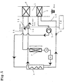
- FIG. 1 is a block diagram of an air conditioner for vehicle according to an embodiment 1 of the present invention.
- An air conditioner for vehicle according to the embodiment 1 includes a refrigerant cycle 13 , a cooling water cycle 14, and a blowing duct 1 for feeding temperature-conditioned air into a vehicle.
- the refrigerant cycle 13 includes an evaporator 2 of performing air cooling by refrigerant evaporation in the blowing duct 1.
- a compressor 3 is installed to increase the pressure of the refrigerant evaporated by the evaporator 3.
- a refrigerant-to-water heat exchanger 4 is also installed to heat cooling water with the refrigerant discharged from the compressor 3.
- an expansion device 5 is mounted to decompress refrigerant discharged from the refrigerant-to-water heat exchanger 4 before it is fed into the evaporator 2.
- the cooling water cycle 14 includes a heater core 6 installed on the downstream side of the evaporator 2 on the basis of the blast direction in the blowing duct 1, a radiator 7 of cooling cooling water, a pump 8 of circulating cooling water cooled by the radiator 7, a power engine 9 of the vehicle cooled by cooling water, and a refrigerant-to-water heat exchanger 4 of warming refrigerant by cooling water.
- the power engine 9 is a heating source such as an engine or a fuel battery.
- the inlet side of cooling water in the refrigerant-to-water heat exchanger 4 serves as the outlet side of refrigerant, and the outlet side of cooling water serves as the inlet side of refrigerant. That is, directions in which cooling water and refrigerant flow are opposite to each other.
- a three-way valve 10 is installed between an outlet of the refrigerant-to-water heat exchanger 4 and an inlet of a heater core 6.
- a bypass circuit 11 connected with the three-way valve 10 as one end and a section between an outlet of the heater core 6 and an inlet of the radiator 7 as the other end.
- a control means 12 is also provided to control the opening direction of the tree-way valve 10 according to an operation mode. Directions in which cooling water flow through the bypass 11 and the heater core 6 are taken as A-direction and B-direction respectively. Arrows in Figure 1 indicate A-direction and B-direction respectively.
- the control means 12 is provided to control the three-way valve 10.
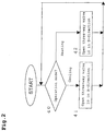
- step 40 It is first detected in step 40 whether the operation mode of the air conditioner is a cooling mode or a heating/dehumidifying mode.
- cooling water flows in A-direction as shown by an arrow.
- refrigerant cycle 13 in the cooling mode when the operation of the air conditioner starts, refrigerant is compressed by the compressor 3 to become high-temperature and high-pressure gas and is heat-radiated to cooling water by the refrigerant-to-water heat exchanger 4.
- the refrigerant heat-radiated by the refrigerant-to-water heat exchanger 4 is decompressed by the expansion device 5 to be changed into a gas-liquid two-phase state under low temperature and low pressure and introduced into the evaporator 2.
- refrigerant is evaporated by heat absorption from the interior air to be changed into a gas-liquid two-phase or a gas state and compressed by the compressor 3.
- blowing air flowing through inside of the blowing duct 1 is cooled and dehumidified by the evaporator 2.
- cooling water is force-fed to the power engine 9 by the pump 8 and heated by the power engine 9.
- cooling water is heated by heat transfer from refrigerant.
- the three-way valve 10 is opened in such a direction that cooling water flows through the bypass 11, high-temperature cooling water flows through the bypass 11. Therefore, high-temperature cooling water does not flow through the heater core 6, so that blowing air in the blowing duct 1 is not heated, and it is finally returned to step 40.
- step 40 when the heating/dehumidifying mode is detected, processing advances to step 42, and the three-way valve 10 is controlled so that cooling water flows through the heater core 6.
- cooling water flows in B-direction indicated by an arrow.
- the refrigerant cycle 13 and a cooling water cycle 14 in the heating/dehumidifying mode are explained below.
- the refrigerant cycle 13 in the heating/dehumidifying mode is the same as for the operation in the coolingmode and an explanation is omitted.
- the refrigerant cycle 13 operates as a dehumidifying function for blowing air in the blowing duct 1.
- high-temperature cooling water heated by the power engine 9 and the refrigerant-to-water heat exchanger 4 flows through the heater core 6.
- blowing air in the blowing duct 1 is warmed up.
- defogging can be performed for a vehicular windshield when an ambient temperature is low.
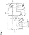
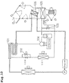
- FIG. 3 is a block diagram of an air conditioner for vehicle according to the embodiment 2 of the present invention.
- the configuration of the refrigerant cycle 26 is the same as for the embodiment 1 and an explanation is thus omitted.
- the cooling cycle 27 is different from that of the embodiment 1 and does not include the three-way valve 10, the bypass 11 or the control means 12.
- a three-way valve 20 is installed between the power engine 9 and the pump 8.
- control means 23 of controlling an opening direction of the three-way valve 20 using a value detected by the power engine outlet water temperature detection means 21.
- Directions in which cooling water flows through the power engine 15 and the bypass 22 are taken as C-direction and D-direction respectively.
- Arrows in Figure 3 indicate C-direction and D-direction respectively.
- the heater core 24 of the embodiment 2 includes a damper 25 unlike the heater core 6 of the embodiment 1.
- the damper 25 is so configured to open and close. When the damper 25 is open, blowing air passes through the heater core 24 and, when the damper 25 is closed, an inflow of blowing air into the heater core 24 is shut down.
- Figure 3 indicates an open state of the damper 25 with a two-dot chain line and its closed state with a solid line.
- the three-way valve 20 is controlled so that cooling water flows into the power engine 9. Cooling water force-fed by the pump 8 is heated by the power engine 9 and is then further heated by the refrigerant-to-water heat exchanger 4. The cooling water flows through the heater core 24 is heat-radiated further by the radiator 7 and is returned to the pump 8. Since the damper 25 of the heater core 24 is closed, blowing air cannot flow through the heater core 25, so that it is not warmed.
- a cooling water temperature T1 detected by the power engine outlet water temperature detection means 21 is compared with a desired setting temperature Tx1 (ex. 40°C) in step 50.
- the Tx1 is a value set so that a blowing air temperature on interior side may not impair comfort at the time of heating/dehumidifying operation.
- the damper 25 opens and its opening degree is adjusted according to the setting temperature Tx1.
- T1 is smaller than Tx1
- the three-way valve 20 is controlled so that cooling water may flow in D-direction; therefore cooling water does not flow into the power engine 9, but through the bypass circuit 22, and only the cooling water heated by the refrigerant-to-water heat exchanger 4 is circulated in the heater core 24.
- the power engine 9 under a low temperature can reduce quantity of heat radiated by the cooling water, enabling the temperature of the cooling water passing through the heater core 24 to rise in a shorter time.
- T1 is at least Tx1 in step 50, on the other hand, this indicates that the temperature of the power engine 9 is sufficiently high and the temperature of cooling water is a fixed value or over; therefore processing advances to step 52.
- the three-way valve 20 is controlled so that cooling water may flow in C-direction; therefore the cooling water heated by the refrigerant-to-water heat exchanger 4 and the power engine 9 flows into the heater core 24. Consequently, the temperature of the cooling water flowing into the heater core 24 can be increased without need for increasing the operation frequency of the compressor 3 for an increase in the heating capacitance of the refrigerant-to-water heat exchanger 4.
- the cooling water flows so that the power engine 9 under a low temperature may be bypassed until the power engine 9 is heated to a fixed temperature.
- the amount of heat radiation can be reduced; therefore the temperature of water flowed into the heater core 24 is raised, which can improve quick warming, that is, comfortableness.
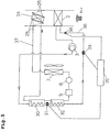
- FIG. 5 is a block diagram of an air conditioner for vehicle according to the embodiment 3 of the present invention.
- the refrigerant cycle 36 includes the evaporator 2 and the compressor 3 like the embodiment 2.
- the first refrigerant-to-water heat exchanger 30 and the second refrigerant-to-water heat exchanger 32, and the first expansion device 31 installed between the two refrigerant-to-water heat exchangers 30, 32 are installed in place of the refrigerant heat exchanger 4 in the embodiment 2.
- the expansion device 12 in the embodiment 2 is corresponding to a second expansion device 33 in the embodiment 3.
- an evaporator inlet refrigerant temperature detection means 34 is installed between the second expansion device 33 and the evaporator 4.
- a control means 35 is installed to control the first expansion device 31 and the second expansion device 33 according to a value of the evaporator inlet refrigerant temperature detection means 34.
- the cooling water cycle 37 does not include the three-way valve 20, the bypass 22, the power engine outlet water temperature detection means 21 or the control means 23 unlike the embodiment 2.
- the first expansion device 31 is controlled to be opened so that refrigerant may not be decompressed and the second expansion device 33 is controlled so that refrigerant may be decompressed.
- the refrigerant subjected to high temperature and high pressure at the compressor 3 is heat-radiated by transmitting heat to cooling water at the first refrigerant-to-water heat exchanger 30 and the second refrigerant-to-water heat exchanger 32.
- refrigerant is decompressed by the first expansion device 31, and blowing air in the blowing duct 1 is cooled/dehumidified by the evaporator 2.
- the cooling water force-fed by the pump 8 is heated by the power engine 9, then heated by the second refrigerant-to-water heat exchanger 33, and heated by the first refrigerant-to-water heat exchanger 30.
- the cooling water flows into the heater core 24.
- the damper 25 of the heater core 24 is closed, and blowing air never flows into the heater core 24, so that blowing air is not warmed, and is then heat-radiated by the radiator 7 and returned to the pump 8.
- a refrigerant temperature T2 detected by the evaporator inlet temperature detection means 34 is compared with a target setting temperature Tx2 (ex. 0°C) in step 60.
- the Tx2 is a temperature preset so that the evaporator 2 may not be frosted.
- step 60 If T2 is smaller than Tx2 in step 60, this indicates the possibility that the evaporator 4 may be frosted. Processing advances to step 61, in which the first expansion device 31 is controlled so that refrigerant may be decompressed and the second expansion device 33 is controlled to be fully opened so that refrigerant may not be decompressed, and processing returns to step 60.
- Figure 7 is a Mollier diagram of a state of the refrigerant cycle 36.
- the heat radiation amount of the first refrigerant-to-water heat exchanger 30 is denoted as Q1
- the heat absorption amount of the second refrigerant-to-water heat exchanger 32 is denoted as Q2
- the heat absorption amount of the evaporator 2 is denoted as Q3.
- the first refrigerant-to-water heat exchnager 30 acts as a radiator and the second refrigerant heat exchanger 32 acts as an evaporator; therefore heat exchange heat-transfer area acting as the evaporator increases and evaporation temperature rises, thus avoiding frosting of the evaporator 2.
- step 62 in which the first expansion device 31 is controlled so as to fully open and the second expansion device 33 is controlled so as to obtain decompression, and processing advances to step 60.
- Figure 8 is a Mollier diagram of a state of the refrigerant cycle 36.
- the heat radiation amount of the first refrigerant-to-water heat exchanger 30 is denoted as Q4
- the heat radiation amount of the second refrigerant-to-water heat exchanger 32 is denoted as Q5
- the heat absorption amount of the evaporator 2 is denoted as Q6.
- the heat absorption amount of the interior evaporator 2 is kept maximum, that is, heating operation is possible while dehumidifying amount is being kept maximum.
- the damper 25 of the heater core 24 is kept open, so that blowing air is warmed by passing through the heater core 24.
- the second refrigerant-to-water heat exchanger 32 is made to act as an evaporator to increase evaporation temperature, thus avoiding frosting of the evaporator 2 without degrading comfortableness.
- This air conditioner for vehicle configured by combining the cooling water cycle 27 of the embodiment 2 with the refrigerant cycle 36 of the embodiment 3 may be used.
- quick warming that is, comfortableness can be improved at start-up immediately after the operation in the heating/dehumidifying mode.
- frosting of the evaporator 2 can be avoided without any impairment of the comfortableness.
- a bypass for connecting an inlet with an outlet of cooling water to the heater core as mentioned in the embodiment 1 may be installed without installing the heater core 24 provided with the damper 25 to form such a configuration that no high-temperature cooling water passes the heater core at the time of cooling.
- Figure 9 is a block diagram of an integrated type of structure of the compressor 3 and a refrigerant-to-water heat exchanger 4 according to the embodiment 4 of the present invention.
- the refrigerant-to-water heat exchanger 4 in Figure 1 is of a double tube and is configured so that refrigerant flows through its inside and water flows through its outside in a counterflow manner.
- the refrigerant-to-water heat exchanger 4 is wound around the compressor 3.
- An enlarged view of A-section indicates an inlet portion of the refrigerator water heat exchanger 4 for refrigerant subjected to high temperature and high pressure by the compressor 3.
- a refrigerant tube is smaller than a cooling water tube, and is configured so as to go into the inside of the cooling water tube from the outlet side of the refrigerant-to-water heat exchanger 4 for cooling water and to go out from the inside of the cooling water tube from the inlet side of the refrigerant-to-water heat exchanger 4 for cooling water.
- the refrigerant-to-water heat exchanger 4 formed out of a double tube is wound around the outer casing of the compressor 3, which provides more space saving than in the case where the compressor 3 and the refrigerant-to-water heat exchanger 4 are installed individually.
- the heat radiation of the compressor can be improved further to restrain an excessive temperature rise in the refrigerant discharged from the compressor 3, thus achieving higher reliability of the air conditioner.
- the heat radiation from the compressor 3 can be used as a heating source for cooling water, thus raising the temperature of water flowing through the heater cores 4 and 24 in a shorter time.
- the configuration of the refrigerant-to-water heat exchanger of the present invention is not limited to the double -tube configuration, and various types of configurations capable of heat transfer between refrigerant and cooling water may be used.
- the refrigerant-to-water heat exchanger of the present invention uses a counterflow arrangement, in which the flowing directions of cooling water and refrigerant are opposite to each other, however, may use the same-direction arrangement.
- refrigerant and cooling water may have a counterflow manner like a water refrigerant heat exchanger of the present invention
- a temperature difference between refrigerant and water is small and a temperature gradient is almost parallel as compared to conventional refrigerant. Therefore, carbon dioxide can be used as refrigerant, and higher heat exchange efficiency can be achieved and the operation of an air conditioner can be performed with high COP (coefficient of performance of refrigerant cycle).
- the first and second expansion devices of the first and second aspects of present inventions correspond to the expansion device 5 in the embodiments 1, 2, and the first and second expansion devices of the fourth aspect of the present invention correspond to the first expansion device 31 and the second expansion device 33 in the embodiment 3.
- the expansion device of the present invention is formed out of a valve capable of adjusting a flow rate, but it is not limited to this configuration.
- Various types of compressor capable of controlling fluid pressure may be used.
- the power engine and air conditioner of the present invention correspond to a power engine and an air conditioner for vehicle in the embodiments 1, 2, 3 or 4.
- the present invention is not limited to use for vehicles, but applicable to various types of power engines and air conditioners used in plans and aircrafts.
- the present invention can provide air conditioning operation while attaining space saving.
- heat radiation amount can be made small, enabling the temperature of water passing through the heater core to rise in a shorter time and improving quick warming or comfortableness.
- evaporation temperature can be raised, thus avoiding frosting of an evaporator without impairing comfortableness.
Landscapes
- Engineering & Computer Science (AREA)
- Physics & Mathematics (AREA)
- Thermal Sciences (AREA)
- Mechanical Engineering (AREA)
- Chemical & Material Sciences (AREA)
- General Engineering & Computer Science (AREA)
- Combustion & Propulsion (AREA)
- Life Sciences & Earth Sciences (AREA)
- Sustainable Development (AREA)
- Sustainable Energy (AREA)
- Chemical Kinetics & Catalysis (AREA)
- Air-Conditioning For Vehicles (AREA)
Abstract
An air conditioner for vehicle is provided for the
purpose of space saving, comprising a refrigerant cycle
13 having: an evaporator 2 which is disposed in a blowing
duct 1 and cools blowing air with refrigerant evaporation;
a compressor 3 of setting the evaporated refrigerant at
high temperature and high pressure; a
refrigerant-to-water heat exchanger 4 of heating cooling water by heat transfer from the refrigerant discharged from the compressor 3; and an expansion device 5 of decompressing the refrigerant discharged from the refrigerant-to-water heat exchanger 4, and a cooling water cycle 14 having: a heater core 6 which is disposed on the downstream side of the evaporator 2 on the basis of a blowing direction in the blowing duct 1 and heats blowing air by the heated cooling water; a radiator 7 of cooling the cooling water; a pump 8 of circulating the cooling water cooled by the radiator 7; a power engine 9 cooled by the cooling water fed by the pump 8; and the refrigerant-to-water heat exchanger 4, wherein the refrigerant cycle 13 performs cooling for
dehumidification at performing the operation of heating.
Description
- The present invention relates to an air conditioner and an air conditioning method.
- In recent years, an electric vehicle has grown in demand from the viewpoint of global environment protection. However, because the capacity of a battery of the electric vehicle is not sufficient, a hybrid electric vehicle which uses an engine for driving assist or for power generation and an electric vehicle which uses a fuel battery for power generation have been proposed.
- The hybrid electric vehicle equipped with the engine for driving assist runs on a vehicle drive motor during urban driving and on the engine if a remaining battery level is low or during suburban driving. On the other hand, the hybrid electric vehicle equipped with the engine for power generation runs on a vehicle drive motor and starts an engine to charge the battery if a remaining battery level becomes low.
- An air conditioner for a present electric vehicle generally drives a compressor (open type) of a refrigerant cycle on a vehicle drive motor. On the other hand, an air conditioner for the above-mentioned hybrid electric vehicle may cool a vehicle compartment inside by driving a compressor on an engine when the engine is in a drive condition. It may cool the vehicle compartment, when the engine is stopping, by driving the compressor using the vehicle drive motor, and, when a remaining battery level is low during the engine stopping, by starting the engine to drive the compressor.
- However, two mechanisms are required: a mechanism for transmitting the rotation of an engine to the compressor and a mechanism for transmitting the rotation of a vehicle drive motor to the compressor, and also required is a clutch for switching these drive methods, increasing the system complexity and the cost.
- On the other hand, a conventional air conditioner is structured so that a vehicle compartment inside may be heated by simply sending air to a heater core supplied with engine cooling water during heating operation, therefore when a temperature of cooling water is low, for example, at engine start-up, long time was required until an air-conditioning temperature in the vehicle compartment inside reaches a target temperature. At a low ambient temperature or the like, heating capacity was too small; therefore engine cooling water was heated with a PTC heater as an auxiliary heating means. Recent engines of other vehicle as well as the hybrid electric vehicle have been highly advanced and heat radiation from the engine has decreased; therefore the engine cooling water was heated with the PTC heater as an auxiliary heating means. Because an electric heater such as the PTC heater was used as an auxiliary heatingmeans, heating efficiency was lower than that of a heat pump type heating apparatus.
- In conventional technology, as shown in Figure 10, a heat pump type refrigerant cycle includes a (sealed type) motor-driven
compressor 104. A refrigerant-to-water heat exchanger 101 was newly attached to its refrigerant circuit as an auxiliary heating means during heating to drive the motor-drivencompressor 104 with afirst solenoid valve 102 closed and with asecond solenoid valve 103 opened if an engine cooling water temperature is not higher than a preset temperature in the case of heating operation designated (refer to Japanese Patent Laid-Open No. 9-66722). The entire disclosure of Japanese Patent Laid-Open No. 9-66722 are incorporated herein by reference in its entirety. - This allows only the refrigerant-to-
water heat exchanger 101 to function as a condenser and no refrigerant tobe supplied to anevaporator 105. As a result, since no low-temperature refrigerant flows through theevaporator 105, the blowing air is not cooled. Therefore engine cooling water additionally heated by the refrigerant-to-water heat exchanger 101 flows through theheater core 106 to heat blowing air in a duct, so that heating capacity was capable of being enhanced without need for a PTC heater even if an engine cooling water temperature was low. - Such an air conditioner is additionally provided with the refrigerant-to-
water heat exchanger 101 as a heating means to heat cooling water. To prevent refrigerant from flowing into theevaporator 105 in heating,solenoid valves valves outdoor heat exchanger 107 are unavoidably necessary, which raises a problem of difficult space saving. - When an engine cooling water temperature is low at the time of heating, even if the refrigerant-to-
water heat exchanger 101 is used as an auxiliary heating means, long time was required until a temperature of refrigerant passing through the refrigerant-to-water heat exchanger 101 rises high enough to start up the air conditioner; therefore there occurred a problem that it took long time for an air-conditioning temperature in a vehicle compartment to reach a target temperature, or that cool air was blown off from a heater core to the vehicle compartment inside. - Furthermore, if the
evaporator 105 was frosted, defrosting operation was conducted, which caused intermittent operation, thus degrading climate pleasure. - In view of the above-mentioned problem, it is an object of the present invention to provide an air conditioner that achieves space saving, shortens the reach time of a target air-conditioning temperature, and prevents climate comfort from being degraded during defrosting.
- The first aspect of the present invention is an air conditioner comprising: a refrigerant cycle having: an evaporator which is disposed in a blowing duct and cools blowing air with refrigerant evaporation; a compressor of setting the evaporated refrigerant at high temperature and high pressure; a refrigerant-to-water heat exchanger of heating cooling water by heat transfer from the refrigerant discharged from said compressor; and an expansion device of decompressing the refrigerant discharged from said refrigerant-to-water heat exchanger, and
a cooling water cycle having: a heater core which is disposed on the downstream side of the evaporator on the basis of a blowing direction in said blowing duct and heats blowing air by the heated cooling water; a radiator of cooling the cooling water; a pump of circulating the cooling water cooled by said radiator; a power engine cooled by the cooling water fed by said pump; and said refrigerant-to-water heat exchanger, wherein the refrigerant cycle performs cooling the air for dehumidification when said air conditioner works as a heater. - The second aspect of the present invention is an air conditioner comprising: a refrigerant cycle having: an evaporator which is disposed in a blowing duct and cools blowing air with refrigerant evaporation; a compressor of setting the evaporated refrigerant at high temperature and high pressure; a refrigerant-to-water heat exchanger of heating cooling water by heat transfer from the refrigerant discharged from said compressor; and an expansion device of decompressing the refrigerant discharged from said refrigerant-to-water heat exchanger, and
a cooling water cycle having: a heater core which is disposed on the downstream side of said evaporator on the basis of a blowing direction in said blowing duct and heats blowing air by the heated cooling water; a radiator of cooling the cooling water; a pump of circulating the cooling water cooled by said radiator; a power engine cooled by the cooling water fed by said pump; a power engine outlet water temperature detection means of measuring a temperature of the cooling water heated by said power engine; a bypass for connecting an inlet with an outlet for the cooling water of said power engine and for preventing passing through said power engine; a three-way valve installed on a branch portion of said bypass at said inlet of said power engine; a control means of controlling an opening degree of the three-way valve with a value detected by said power engine outlet water temperature detection means; and a cooling water cycle having said refrigerant-to-water heat exchanger. - The third aspect of the present invention is the air conditioner according to the second aspect of the present invention, wherein said control means is a control means of controlling a three-way valve so that the cooling water may bypass said power engine if the power engine outlet water temperature is lower than a prescribed threshold value, and so that the cooling water may flow into said power engine if the power engine outlet water temperature is higher than a prescribed threshold value.
- The fourth aspect of the present invention is an air conditioner comprising: a refrigerant cycle having: an evaporator which is disposed in a blowing duct and cools with refrigerant vapor; a compressor of setting the evaporated refrigerant at high temperature and high pressure; a first refrigerant-to-water heat exchanger of heating cooling water by heat transfer from the refrigerant discharged from said compressor; a first expansion device of controlling the decompression of the refrigerant discharged from said first refrigerant-to-water heat exchanger; a second refrigerant-to-water heat exchanger of transferring heat between the refrigerant discharged from said first expansion device and the cooling water; a second expansion device of controlling decompression of the refrigerant discharged from said second refrigerant-to-water heat exchanger; an evaporator inlet refrigerant temperature detection means of measuring a temperature of the refrigerant of which decompression is controlled by said second expansion device; a control means of controlling said first expansion device and said second expansion device using a value detected by said evaporator inlet refrigerant temperature detection means, and
a cooling water cycle having: a heater core which is disposed on the downstream side of said evaporator on the basis of a blowing direction in said blowing duct and heats blowing air by the heated cooling water; a radiator of cooling the cooling water; a pump of circulating the cooling water cooled by said radiator; a power engine cooled by the cooling water fed by said pump; and said first refrigerant-to-water heat exchanger and said second refrigerant-to-water heat exchanger. - The fifth aspect of the present invention is the air conditioner according to the fourth aspect of the present invention, wherein the control means is a control means of performing pressure control so that refrigerant may be decompressed by said first expansion device and the second expansion device may be opened if said evaporator inlet refrigerant temperature is lower than such a temperature that frost adheres to said evaporator, and so that said first expansion device may be opened and the refrigerant may be decompressed by said second expansion device if said evaporator inlet refrigerant temperature is higher than such a temperature that frost adheres to said evaporator.
- The sixth aspect of the present invention is the air conditioner according to any one of the first, the second or the fourth aspects of the present invention, wherein said refrigerant-to-water heat exchanger is a refrigerant-to-water heat exchanger which has flowing directions of the refrigerant and the cooling water is reverse each other.
- The seventh aspect of the present invention is the air conditioner according to any one of the first, the second or the fourth aspects of the present invention, wherein said refrigerant-to-water heat exchanger is a refrigerant-to-water heat exchanger wound around said compressor.
- The eighth aspect of the present invention is the air conditioner according to the sixth aspect of the present invention, wherein carbon dioxide is used as the refrigerant.
- The ninth aspect of the present invention is the air conditioner according to any one of the first, the second or the fourth aspects of the present invention, further comprising: a bypass for connecting an inlet with an outlet for the cooling water of the heater core and for preventing passing through said heater core; a three-way valve installed on a branch portion of said bypass at said inlet of said heater core; a control means of controlling an opening degree of said three-way valve in accordance with an operation mode.
- The tenth aspect of the present invention is the air conditioner according to any one of the first, the second or the fourth aspects of the present invention, wherein said blowing duct is a blowing duct for blowing air into a vehicle compartment and said power engine is a power engine for a vehicle.
- The eleventh aspect of the present invention is an air conditioning method using said air conditioner according to the first aspect of the present invention, comprising: a refrigerant cycle step having: an evaporation step of cooling said blowing air by the evaporation of the refrigerant in said blowing duct; a compression step of keeping the evaporated refrigerant at a high temperature and at a high pressure; a refrigerant-to-water heat exchange step of heating the cooling water by heat transfer from said refrigerant discharged from said compression step; and a decompression step of decompressing the refrigerant discharged from said refrigerant-to-water heat exchange step, and
a cooling water cycle step having: a step of warming the blowing air by the heated cooling water on the downstream side of said evaporation step on the basis of a blowing direction in said blowing duct, a cooling step of cooling the cooling water with said radiator, a step of circulating the cooling water cooled by said radiator, a step of cooling said power engine using the cooling water discharged by said pump, and said refrigerant-to-water heat exchange step, and which performs cooling the air for dehumidification by means of said refrigerant cycle when said air conditioner works as a heater. - The twelfth aspect of the present invention is an air conditioning method using said air conditioner according to the second aspect of the present invention, comprising: a refrigerant cycle step having: an evaporation step of cooling the blowing air by the evaporation of the refrigerant in said blowing duct; a compression step of keeping the evaporated refrigerant at a high temperature and at a high pressure; a refrigerant-to-water heat exchange step of heating the cooling water by heat transfer from said refrigerant discharged from said compression step; and a decompression step of decompressing the refrigerant discharged from said refrigerant-to-water heat exchange step, and
a cooling water cycle step having: a step of warming the blowing air by the heated cooling water on the downstream side of said evaporation step on the basis of a blowing direction in said blowing duct; a cooling step of cooling the cooling water with said radiator; a step of circulating the cooling water cooled by said radiator; a step of cooling the power engine using the cooling water discharged by said pump; a power engine outlet water temperature detection step of measuring a temperature of the cooling water heated by said power engine; a step of controlling said three-way valve; and said refrigerant-to-water heat exchange step. - The thirteenth aspect of the present invention is an air conditioning method using said air conditioner according to the fourth aspect of the present invention, comprising: a refrigerant cycle step having: an evaporation step of cooling the blowing air by the evaporation of the refrigerant in said blowing duct; a compression step of keeping the evaporated refrigerant at a high temperature and at a high pressure; a first refrigerant-to-water heat exchange step of heating the cooling water by heat transfer from the refrigerant discharged from said compression step; a first decompression step of controlling decompression of the refrigerant discharged from said first refrigerant-to-water heat exchange step; a second refrigerant-to-water heat exchange step of transferring heat between the refrigerant discharged from said first decompression step and the cooling water; a second decompression step of controlling decompression of the refrigerant discharged from said second refrigerant-to-water heat exchange step; an evaporator inlet refrigerant temperature detection step of measuring a temperature of the refrigerant of which decompression is controlled by the second decompression step; a step of controlling said first decompression step and said second compression step using a value detected by said evaporator inlet refrigerant temperature detection step, and
a cooling water cycle step having: a step of warming blowing air by the heated cooling water in said heater core installed on the downstream side of said evaporator on the basis of a blowing direction in said blowing duct; a cooling step of cooling the cooling water with said radiator; a step of circulating the cooling water cooled by said radiator; a step of cooling said power engine using the cooling water discharged by said pump; said first refrigerant-to-water heat exchange step; and said second refrigerant-to-water heat exchange step. -
- Figure 1 is a block diagram of an air conditioner
for vehicle according to an
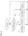
embodiment 1 of the present invention; - Figure 2 is a control flow chart of an air conditioner
for vehicle according to the
embodiment 1 of the present invention; - Figure 3 is a block diagram of an air conditioner
for vehicle according to the
embodiment 2 of the present invention; - Figure 4 is a control flow chart of an air conditioner
for vehicle according to the
embodiment 2 of the present invention; - Figure 5 is a block diagram of an air conditioner
for vehicle according to the
embodiment 3 of the present invention; - Figure 6 is a control flow chart of an air conditioner
for vehicle according to the
embodiment 3 of the present invention; - Figure 7 is a Mollier diagram of an air conditioner
for vehicle according to the
embodiment 3 of the present invention; - Figure 8 is a Mollier diagram of an air conditioner
for vehicle according to the
embodiment 3 of the present invention; - Figure 9 is a block diagram of a compressor and a
refrigerant-to-water heat exchanger according to the
embodiment 4 of the present invention; and - Figure 10 is a block diagram of a conventional air conditioner for vehicle.
-
-
- 1:
- blowing duct
- 2:
- evaporator
- 3:
- compressor
- 4:
- refrigerant-to-water heat exchanger
- 5:
- expansion device
- 6:
- heater core
- 7:
- radiator
- 8:
- pump
- 9:
- power engine
- 10:
- three-way valve
- 11:
- bypass circuit
- 12:
- control means
- 13:
- refrigerant cycle
- 14:
- cooling water cycle
- Embodiments of the present invention are explained hereinafter in conjunction with drawings.
- Figure 1 is a block diagram of an air conditioner for vehicle according to an
embodiment 1 of the present invention. An air conditioner for vehicle according to theembodiment 1 includes arefrigerant cycle 13 , a coolingwater cycle 14, and a blowingduct 1 for feeding temperature-conditioned air into a vehicle. - The
refrigerant cycle 13 includes anevaporator 2 of performing air cooling by refrigerant evaporation in the blowingduct 1. Acompressor 3 is installed to increase the pressure of the refrigerant evaporated by theevaporator 3. A refrigerant-to-water heat exchanger 4 is also installed to heat cooling water with the refrigerant discharged from thecompressor 3. In addition, anexpansion device 5 is mounted to decompress refrigerant discharged from the refrigerant-to-water heat exchanger 4 before it is fed into theevaporator 2. - The cooling
water cycle 14 includes a heater core 6 installed on the downstream side of theevaporator 2 on the basis of the blast direction in the blowingduct 1, aradiator 7 of cooling cooling water, apump 8 of circulating cooling water cooled by theradiator 7, apower engine 9 of the vehicle cooled by cooling water, and a refrigerant-to-water heat exchanger 4 of warming refrigerant by cooling water. Thepower engine 9 is a heating source such as an engine or a fuel battery. - The inlet side of cooling water in the refrigerant-to-
water heat exchanger 4 serves as the outlet side of refrigerant, and the outlet side of cooling water serves as the inlet side of refrigerant. That is, directions in which cooling water and refrigerant flow are opposite to each other. - A three-
way valve 10 is installed between an outlet of the refrigerant-to-water heat exchanger 4 and an inlet of a heater core 6. There is also provided a bypass circuit 11 connected with the three-way valve 10 as one end and a section between an outlet of the heater core 6 and an inlet of theradiator 7 as the other end. Moreover, a control means 12 is also provided to control the opening direction of the tree-way valve 10 according to an operation mode. Directions in which cooling water flow through the bypass 11 and the heater core 6 are taken as A-direction and B-direction respectively. Arrows in Figure 1 indicate A-direction and B-direction respectively. The control means 12 is provided to control the three-way valve 10. - The operation of the air conditioner for vehicle of the above configuration is explained below using a flow chart as shown in Figure 2.
- It is first detected in
step 40 whether the operation mode of the air conditioner is a cooling mode or a heating/dehumidifying mode. - When it is detected as the cooling mode, processing advances to step 41 and the three-
way valve 10 is controlled so that high-temperature cooling water may flow through the bypass 11. In Figure 1, cooling water flows in A-direction as shown by an arrow. - The operation of the
refrigerant cycle 13 and the coolingwater cycle 14 in a cooling mode is explained below. - At the
refrigerant cycle 13 in the cooling mode, when the operation of the air conditioner starts, refrigerant is compressed by thecompressor 3 to become high-temperature and high-pressure gas and is heat-radiated to cooling water by the refrigerant-to-water heat exchanger 4. Next, the refrigerant heat-radiated by the refrigerant-to-water heat exchanger 4 is decompressed by theexpansion device 5 to be changed into a gas-liquid two-phase state under low temperature and low pressure and introduced into theevaporator 2. In theevaporator 2, refrigerant is evaporated by heat absorption from the interior air to be changed into a gas-liquid two-phase or a gas state and compressed by thecompressor 3. Thus, blowing air flowing through inside of the blowingduct 1 is cooled and dehumidified by theevaporator 2. - At a cooling
water cycle 14 , cooling water is force-fed to thepower engine 9 by thepump 8 and heated by thepower engine 9. At the refrigerant-to-water heat exchanger 4, cooling water is heated by heat transfer from refrigerant. Next, since the three-way valve 10 is opened in such a direction that cooling water flows through the bypass 11, high-temperature cooling water flows through the bypass 11. Therefore, high-temperature cooling water does not flow through the heater core 6, so that blowing air in the blowingduct 1 is not heated, and it is finally returned to step 40. - In
step 40, when the heating/dehumidifying mode is detected, processing advances to step 42, and the three-way valve 10 is controlled so that cooling water flows through the heater core 6. In Figure 1, cooling water flows in B-direction indicated by an arrow. - The
refrigerant cycle 13 and a coolingwater cycle 14 in the heating/dehumidifying mode are explained below. - The
refrigerant cycle 13 in the heating/dehumidifying mode is the same as for the operation in the coolingmode and an explanation is omitted. Therefrigerant cycle 13 operates as a dehumidifying function for blowing air in the blowingduct 1. At the coolingwater cycle 14, high-temperature cooling water heated by thepower engine 9 and the refrigerant-to-water heat exchanger 4 flows through the heater core 6. Herein blowing air in the blowingduct 1 is warmed up. - By using the
refrigerant cycle 13 for dehumidification in the heating mode as well, use ofsolenoid valves valve 108, andexterior heat exchanger 107 and so on, which was conventionally needed, can be eliminated, thus achieving space saving. - In the heating/dehumidifying mode, defogging can be performed for a vehicular windshield when an ambient temperature is low.
- The basic configuration of an air conditioner for vehicle according to an
embodiment 2 of the present invention is the same as that of theembodiment 1 and is explained with a focus placed on differences between them. The same constituent elements as for theembodiment 1 have the same numbers on them. - Figure 3 is a block diagram of an air conditioner for vehicle according to the
embodiment 2 of the present invention. - The configuration of the
refrigerant cycle 26 is the same as for theembodiment 1 and an explanation is thus omitted. The coolingcycle 27 is different from that of theembodiment 1 and does not include the three-way valve 10, the bypass 11 or the control means 12. A three-way valve 20 is installed between thepower engine 9 and thepump 8. There is provided a bypass 22 connected with the three-way valve 20 as one end and a section between the power engine outlet water temperature means 21 and the refrigerant-to-water heat exchanger 4 as the other end. - There is also provided a control means 23 of controlling an opening direction of the three-
way valve 20 using a value detected by the power engine outlet water temperature detection means 21. Directions in which cooling water flows through the power engine 15 and the bypass 22 are taken as C-direction and D-direction respectively. Arrows in Figure 3 indicate C-direction and D-direction respectively. - The
heater core 24 of theembodiment 2 includes adamper 25 unlike the heater core 6 of theembodiment 1. Thedamper 25 is so configured to open and close. When thedamper 25 is open, blowing air passes through theheater core 24 and, when thedamper 25 is closed, an inflow of blowing air into theheater core 24 is shut down. Figure 3 indicates an open state of thedamper 25 with a two-dot chain line and its closed state with a solid line. - The operation of the air conditioner for vehicle of the above configuration is explained below. The operation in the cooling mode is first described. At the
refrigerant cycle 26, the same operation as that of theembodiment 1 is performed, therefore the description of its operation is omitted. - At the cooling
water cycle 27, the three-way valve 20 is controlled so that cooling water flows into thepower engine 9. Cooling water force-fed by thepump 8 is heated by thepower engine 9 and is then further heated by the refrigerant-to-water heat exchanger 4. The cooling water flows through theheater core 24 is heat-radiated further by theradiator 7 and is returned to thepump 8. Since thedamper 25 of theheater core 24 is closed, blowing air cannot flow through theheater core 25, so that it is not warmed. - Next, the operation of the three-
way valve 20 in the heating/dehumidifying mode is explained using the flow chart shown in Figure 4. At therefrigerant cycle 26, the same operation as that of theembodiment 1 is performed, therefore the description of its operation is omitted. - At the cooling
water cycle 27, when the operation of the heating/dehumidifying mode starts, a cooling water temperature T1 detected by the power engine outlet water temperature detection means 21 is compared with a desired setting temperature Tx1 (ex. 40°C) instep 50. The Tx1 is a value set so that a blowing air temperature on interior side may not impair comfort at the time of heating/dehumidifying operation. In the heating/dehumidifying mode, thedamper 25 opens and its opening degree is adjusted according to the setting temperature Tx1. - If T1 is smaller than Tx1, this indicates a temperature of the
power engine 9 is low; therefore processing advances to step 51. The three-way valve 20 is controlled so that cooling water may flow in D-direction; therefore cooling water does not flow into thepower engine 9, but through the bypass circuit 22, and only the cooling water heated by the refrigerant-to-water heat exchanger 4 is circulated in theheater core 24. As a result, thepower engine 9 under a low temperature can reduce quantity of heat radiated by the cooling water, enabling the temperature of the cooling water passing through theheater core 24 to rise in a shorter time. - The blowing air flowed into the
heater core 24 with thedamper 25 opened is warmed by the heated cooling water. After the completion of this control, processing returns to step 50. - If T1 is at least Tx1 in
step 50, on the other hand, this indicates that the temperature of thepower engine 9 is sufficiently high and the temperature of cooling water is a fixed value or over; therefore processing advances to step 52. The three-way valve 20 is controlled so that cooling water may flow in C-direction; therefore the cooling water heated by the refrigerant-to-water heat exchanger 4 and thepower engine 9 flows into theheater core 24. Consequently, the temperature of the cooling water flowing into theheater core 24 can be increased without need for increasing the operation frequency of thecompressor 3 for an increase in the heating capacitance of the refrigerant-to-water heat exchanger 4. - The blowing air flowed into the
heater core 24 with thedamper 25 opened is warmed by the heated cooling water. After the completion of this control, processing returns to step 50. - By controlling the three-
way valve 20 at start-up immediately after an operation in the heating/dehumidifying mode, the cooling water flows so that thepower engine 9 under a low temperature may be bypassed until thepower engine 9 is heated to a fixed temperature. As a result, the amount of heat radiation can be reduced; therefore the temperature of water flowed into theheater core 24 is raised, which can improve quick warming, that is, comfortableness. - The basic configuration of an air conditioner for vehicle according to an
embodiment 3 of the present invention is the same as that of theembodiment 2 and is explained with a focus placed on differences between them. The same constituent elements as for theembodiment 2 have the same numbers on them. - Figure 5 is a block diagram of an air conditioner for vehicle according to the
embodiment 3 of the present invention. - The
refrigerant cycle 36 includes theevaporator 2 and thecompressor 3 like theembodiment 2. In theembodiment 3, the first refrigerant-to-water heat exchanger 30 and the second refrigerant-to-water heat exchanger 32, and thefirst expansion device 31 installed between the two refrigerant-to-water heat exchangers refrigerant heat exchanger 4 in theembodiment 2. Theexpansion device 12 in theembodiment 2 is corresponding to asecond expansion device 33 in theembodiment 3. - Between the
second expansion device 33 and theevaporator 4, an evaporator inlet refrigerant temperature detection means 34 is installed. A control means 35 is installed to control thefirst expansion device 31 and thesecond expansion device 33 according to a value of the evaporator inlet refrigerant temperature detection means 34. The coolingwater cycle 37 does not include the three-way valve 20, the bypass 22, the power engine outlet water temperature detection means 21 or the control means 23 unlike theembodiment 2. - The operation of the air conditioner for vehicle of the above configuration is explained below.
- The operation in the cooling mode is first described.
- At the
refrigerant cycle 36 in the cooling mode, thefirst expansion device 31 is controlled to be opened so that refrigerant may not be decompressed and thesecond expansion device 33 is controlled so that refrigerant may be decompressed. As a result, the refrigerant subjected to high temperature and high pressure at thecompressor 3 is heat-radiated by transmitting heat to cooling water at the first refrigerant-to-water heat exchanger 30 and the second refrigerant-to-water heat exchanger 32. Next, refrigerant is decompressed by thefirst expansion device 31, and blowing air in the blowingduct 1 is cooled/dehumidified by theevaporator 2. - In the cooling
water cycle 37, the cooling water force-fed by thepump 8 is heated by thepower engine 9, then heated by the second refrigerant-to-water heat exchanger 33, and heated by the first refrigerant-to-water heat exchanger 30. Next, the cooling water flows into theheater core 24. Thedamper 25 of theheater core 24 is closed, and blowing air never flows into theheater core 24, so that blowing air is not warmed, and is then heat-radiated by theradiator 7 and returned to thepump 8. - The operations of the
first expansion device 30 and thesecond expansion device 32 in the heating/dehumidifying mode are explained below, using a flow chart of Figure 6. - At the
refrigerant cycle 36, in the heating/dehumidifying mode, first, a refrigerant temperature T2 detected by the evaporator inlet temperature detection means 34 is compared with a target setting temperature Tx2 (ex. 0°C) instep 60. The Tx2 is a temperature preset so that theevaporator 2 may not be frosted. - If T2 is smaller than Tx2 in
step 60, this indicates the possibility that theevaporator 4 may be frosted. Processing advances to step 61, in which thefirst expansion device 31 is controlled so that refrigerant may be decompressed and thesecond expansion device 33 is controlled to be fully opened so that refrigerant may not be decompressed, and processing returns to step 60. - Figure 7 is a Mollier diagram of a state of the
refrigerant cycle 36. The heat radiation amount of the first refrigerant-to-water heat exchanger 30 is denoted as Q1, the heat absorption amount of the second refrigerant-to-water heat exchanger 32 is denoted as Q2, and the heat absorption amount of theevaporator 2 is denoted as Q3. In theembodiment 3, the first refrigerant-to-water heat exchnager 30 acts as a radiator and the secondrefrigerant heat exchanger 32 acts as an evaporator; therefore heat exchange heat-transfer area acting as the evaporator increases and evaporation temperature rises, thus avoiding frosting of theevaporator 2. - If T2 is Tx2 or higher, there is low possibility of the
evaporator 2 being frosted, and processing advances to step 62, in which thefirst expansion device 31 is controlled so as to fully open and thesecond expansion device 33 is controlled so as to obtain decompression, and processing advances to step 60. - Figure 8 is a Mollier diagram of a state of the
refrigerant cycle 36. The heat radiation amount of the first refrigerant-to-water heat exchanger 30 is denoted as Q4, the heat radiation amount of the second refrigerant-to-water heat exchanger 32 is denoted as Q5, and the heat absorption amount of theevaporator 2 is denoted as Q6. In theembodiment 3, the heat absorption amount of theinterior evaporator 2 is kept maximum, that is, heating operation is possible while dehumidifying amount is being kept maximum. - At the cooling
water cycle 37 in the heating/dehumidifying mode, thedamper 25 of theheater core 24 is kept open, so that blowing air is warmed by passing through theheater core 24. - By controlling the
first expansion device 31 and thesecond expansion device 33 in the heating/dehumidifying mode, the second refrigerant-to-water heat exchanger 32 is made to act as an evaporator to increase evaporation temperature, thus avoiding frosting of theevaporator 2 without degrading comfortableness. - This air conditioner for vehicle configured by combining the cooling
water cycle 27 of theembodiment 2 with therefrigerant cycle 36 of theembodiment 3 may be used. In this case, quick warming, that is, comfortableness can be improved at start-up immediately after the operation in the heating/dehumidifying mode. Moreover, frosting of theevaporator 2 can be avoided without any impairment of the comfortableness. - In the
embodiments embodiment 1 may be installed without installing theheater core 24 provided with thedamper 25 to form such a configuration that no high-temperature cooling water passes the heater core at the time of cooling. - Figure 9 is a block diagram of an integrated type of structure of the
compressor 3 and a refrigerant-to-water heat exchanger 4 according to theembodiment 4 of the present invention. - The refrigerant-to-
water heat exchanger 4 in Figure 1 is of a double tube and is configured so that refrigerant flows through its inside and water flows through its outside in a counterflow manner. The refrigerant-to-water heat exchanger 4 is wound around thecompressor 3. An enlarged view of A-section indicates an inlet portion of the refrigeratorwater heat exchanger 4 for refrigerant subjected to high temperature and high pressure by thecompressor 3. As illustrated, a refrigerant tube is smaller than a cooling water tube, and is configured so as to go into the inside of the cooling water tube from the outlet side of the refrigerant-to-water heat exchanger 4 for cooling water and to go out from the inside of the cooling water tube from the inlet side of the refrigerant-to-water heat exchanger 4 for cooling water. - The refrigerant-to-
water heat exchanger 4 formed out of a double tube is wound around the outer casing of thecompressor 3, which provides more space saving than in the case where thecompressor 3 and the refrigerant-to-water heat exchanger 4 are installed individually. - In the cooling mode, the heat radiation of the compressor can be improved further to restrain an excessive temperature rise in the refrigerant discharged from the
compressor 3, thus achieving higher reliability of the air conditioner. - In the heating/dehumidifying mode, the heat radiation from the
compressor 3 can be used as a heating source for cooling water, thus raising the temperature of water flowing through theheater cores - The configuration of the refrigerant-to-water heat exchanger of the present invention is not limited to the double -tube configuration, and various types of configurations capable of heat transfer between refrigerant and cooling water may be used.
- The refrigerant-to-water heat exchanger of the present invention uses a counterflow arrangement, in which the flowing directions of cooling water and refrigerant are opposite to each other, however, may use the same-direction arrangement.
- However, in the case of HCFC refrigerant or HFC refrigerant which has been conventionally used, a temperature change in the refrigerant is seldom found while a gas-liquid two-phase is being condensed. In the case that refrigerant is carbon dioxide, high-pressure side is supercritical cycle; therefore heat radiation is performed while a temperature change is always being made.
- Where heat exchange is performed so that refrigerant and cooling water may have a counterflow manner like a water refrigerant heat exchanger of the present invention, a temperature difference between refrigerant and water is small and a temperature gradient is almost parallel as compared to conventional refrigerant. Therefore, carbon dioxide can be used as refrigerant, and higher heat exchange efficiency can be achieved and the operation of an air conditioner can be performed with high COP (coefficient of performance of refrigerant cycle).
- The first and second expansion devices of the first and second aspects of present inventions correspond to the
expansion device 5 in theembodiments first expansion device 31 and thesecond expansion device 33 in theembodiment 3. In theembodiments - The power engine and air conditioner of the present invention correspond to a power engine and an air conditioner for vehicle in the
embodiments - As can be clearly understood from the foregoing explanation, the present invention can provide air conditioning operation while attaining space saving.
- At the time of start-up immediately after heating/dehumidifying mode operation, heat radiation amount can be made small, enabling the temperature of water passing through the heater core to rise in a shorter time and improving quick warming or comfortableness.
- In the heating/dehumidifying mode, evaporation temperature can be raised, thus avoiding frosting of an evaporator without impairing comfortableness.
- By adopting such an integrated type of structure that a refrigerant-to-water heat exchanger covers the outer casing of a compressor, space saving can be achieved.
- By using carbon dioxide as refrigerant, higher heat exchange efficiency than conventional refrigerant can be attained to realize air conditioning operation with high COP.
Claims (6)
- An air conditioner comprising:wherein the refrigerant cycle performs cooling the air for dehumidification when said air conditioner works as a heater.a refrigerant cycle having:an evaporator which is disposed in a blowing duct and cools blowing air with refrigerant evaporation; a compressor of setting the evaporated refrigerant at high temperature and high pressure; a refrigerant-to-water heat exchanger of heating cooling water by heat transfer from the refrigerant discharged from said compressor; and an expansion device of decompressing the refrigerant discharged from said refrigerant-to-water heat exchanger, anda cooling water cycle having: a heater core which is disposed on the downstream side of the evaporator on the basis of a blowing direction in said blowing duct and heats blowing air by the heated cooling water; a radiator of cooling the cooling water; a pump of circulating the cooling water cooled by said radiator;a power engine cooled by the cooling water fed by said pump; and said refrigerant-to-water heat exchanger,
- The air conditioner according to claim 1, wherein said refrigerant-to-water heat exchanger is a refrigerant-to-water heat exchanger which has flowing directions of the refrigerant and the cooling water is reverse each other.
- The air conditioner according to claim 1, wherein said refrigerant-to-water heat exchanger is a refrigerant-to-water heat exchanger wound around said compressor.
- The air conditioner according to claim 3, wherein carbon dioxide is used as the refrigerant.
- The air conditioner according to claim 1, further comprising: a bypass for connectingan inlet with an outlet for the cooling water of the heater core and for preventing passing through said heater core; a three-way valve installed on a branch portion of said bypass at said inlet of said heater core; a control means of controlling an opening degree of said three-way valve in accordance with an operation mode.
- The air conditioner according to claim 1, wherein said blowing duct is a blowing duct for blowing air into a vehicle compartment and said power engine is a power engine for a vehicle.
Applications Claiming Priority (3)
| Application Number | Priority Date | Filing Date | Title |
|---|---|---|---|
| JP2002355430 | 2002-12-06 | ||
| JP2002355430A JP3736847B2 (en) | 2002-12-06 | 2002-12-06 | Air conditioning apparatus and air conditioning method |
| PCT/JP2003/015449 WO2004056594A1 (en) | 2002-12-06 | 2003-12-03 | Air conditioner |
Publications (1)
| Publication Number | Publication Date |
|---|---|
| EP1568524A1 true EP1568524A1 (en) | 2005-08-31 |
Family
ID=32677058
Family Applications (1)
| Application Number | Title | Priority Date | Filing Date |
|---|---|---|---|
| EP03777181A Withdrawn EP1568524A1 (en) | 2002-12-06 | 2003-12-03 | Air conditioner |
Country Status (4)
| Country | Link |
|---|---|
| US (1) | US7069983B2 (en) |
| EP (1) | EP1568524A1 (en) |
| JP (1) | JP3736847B2 (en) |
| WO (1) | WO2004056594A1 (en) |
Cited By (5)
| Publication number | Priority date | Publication date | Assignee | Title |
|---|---|---|---|---|
| EP2072298A4 (en) * | 2007-02-20 | 2009-12-02 | Calsonic Kansei Corp | AIR CONDITIONING FOR VEHICLE |
| WO2011079904A1 (en) * | 2009-12-30 | 2011-07-07 | Voss Automotive Gmbh | Climate control system for a vehicle and method for controlling temperature |
| CN102252388A (en) * | 2011-06-23 | 2011-11-23 | 陈创军 | Water/coolant integrated automobile air conditioning system |
| WO2011148071A1 (en) * | 2010-05-25 | 2011-12-01 | Peugeot Citroën Automobiles SA | Heating/air-conditioning installation with external and contiguous condenser and evaporator for heating the external evaporator |
| CN102795095A (en) * | 2011-05-27 | 2012-11-28 | 康奈可关精株式会社 | Combined heat exchanger |
Families Citing this family (37)
| Publication number | Priority date | Publication date | Assignee | Title |
|---|---|---|---|---|
| JP3736847B2 (en) * | 2002-12-06 | 2006-01-18 | 松下電器産業株式会社 | Air conditioning apparatus and air conditioning method |
| JP2006182344A (en) * | 2004-12-02 | 2006-07-13 | Valeo Thermal Systems Japan Corp | Air conditioner for vehicle |
| FR2897016A1 (en) * | 2006-02-09 | 2007-08-10 | Vehicules Electr Societe Par A | ELECTRIC OR HYBRID AUTOMOTIVE VEHICLE HAVING A THERMAL CONDITIONING SYSTEM PROVIDING LOW LEVEL SOURCES |
| US8517087B2 (en) * | 2007-02-20 | 2013-08-27 | Bergstrom, Inc. | Combined heating and air conditioning system for vehicles |
| US7264046B1 (en) * | 2007-03-13 | 2007-09-04 | Vladlen Futernik | Air-conditioning system |
| US8740103B2 (en) * | 2008-04-21 | 2014-06-03 | GM Global Technology Operations LLC | Heater coolant flow control for HVAC module |
| JP5494312B2 (en) * | 2009-09-03 | 2014-05-14 | 株式会社デンソー | Air conditioner for vehicles |
| JP2011126491A (en) * | 2009-12-21 | 2011-06-30 | Calsonic Kansei Corp | Vehicular air conditioner |
| KR101585943B1 (en) * | 2010-02-08 | 2016-01-18 | 삼성전자 주식회사 | Air conditioner and control method thereof |
| DE102011109055A1 (en) | 2010-09-04 | 2012-03-08 | Volkswagen Ag | Aircondition for a vehicle and method for air conditioning a vehicle |
| KR101189417B1 (en) * | 2010-11-30 | 2012-10-15 | 기아자동차주식회사 | Temperature Control Apparatus for Vehicle |
| KR101735115B1 (en) * | 2011-01-10 | 2017-05-12 | 주식회사 두원공조 | Air conditioner system for vehicle |
| US9573437B2 (en) * | 2011-02-21 | 2017-02-21 | Hitachi, Ltd. | Vehicular air conditioning system |
| JP5578141B2 (en) * | 2011-07-05 | 2014-08-27 | 株式会社デンソー | Air conditioner for vehicles |
| FR2992905B1 (en) * | 2012-07-03 | 2016-03-11 | Renault Sas | VEHICLE HAVING REVERSE ENGINE AND POSSESSING AN IMPROVED CLUTCH SYSTEM |
| JP5664741B2 (en) * | 2012-11-22 | 2015-02-04 | ダイキン工業株式会社 | Container refrigeration equipment |
| US20140209278A1 (en) * | 2013-01-30 | 2014-07-31 | Visteon Global Technologies, Inc. | Thermal energy storage system with heat pump, reduced heater core, and integrated battery cooling and heating |
| CN103743015A (en) * | 2013-12-28 | 2014-04-23 | 柳州力通车用空调有限公司 | Water cooling device for vehicle air conditioner |
| US9925847B2 (en) | 2014-03-10 | 2018-03-27 | Tiger Tool International Incorporated | Heating and cooling systems and methods for truck cabs |
| US10302346B2 (en) * | 2014-07-16 | 2019-05-28 | Ford Global Technologies, Llc | Maximizing defrost mode in electrified vehicle having dual evaporator and dual heater core climate control system |
| JP6470026B2 (en) * | 2014-12-04 | 2019-02-13 | サンデンホールディングス株式会社 | Air conditioner for vehicles |
| JP6390431B2 (en) * | 2015-01-07 | 2018-09-19 | 株式会社デンソー | Refrigeration cycle equipment |
| EP3246222B1 (en) * | 2015-01-13 | 2022-12-28 | Mitsubishi Electric Corporation | Vehicle air-conditioning device |
| CN106855279B (en) * | 2015-12-08 | 2022-10-25 | 维谛技术有限公司 | Air conditioning system, refrigeration control method and device |
| USD801501S1 (en) | 2016-01-04 | 2017-10-31 | Tiger Tool International Incorporated | Housing for an evaporator |
| USD801500S1 (en) | 2016-01-04 | 2017-10-31 | Tiger Tool International Incorporated | Housing for a condenser |
| WO2017132260A1 (en) | 2016-01-25 | 2017-08-03 | Tiger Tool Intenational Incorporated | Air conditioning systems and methods for vehicle. |
| US10220674B2 (en) * | 2016-10-07 | 2019-03-05 | Toyota Motor Engineering & Manufacturing North America, Inc. | Target evaporator outlet temperature maps for vehicle air conditioning control |
| US10214078B2 (en) * | 2016-10-20 | 2019-02-26 | Toyota Motor Engineering & Manufacturing North America, Inc. | AC cut cycles for vehicle air conditioning control based on high ambient temperature |
| JP2019060580A (en) * | 2017-09-28 | 2019-04-18 | 株式会社デンソー | Refrigeration cycle device |
| CN108518319B (en) * | 2018-03-09 | 2023-12-29 | 远景能源有限公司 | Tower bottom cooling and dehumidifying system of offshore wind generating set and control method |
| US11407283B2 (en) | 2018-04-30 | 2022-08-09 | Tiger Tool International Incorporated | Cab heating systems and methods for vehicles |
| US11993130B2 (en) | 2018-11-05 | 2024-05-28 | Tiger Tool International Incorporated | Cooling systems and methods for vehicle cabs |
| US11186142B2 (en) * | 2019-05-19 | 2021-11-30 | Hyundai Motor Company | Engine HSG loading for rapid cabin warmup |
| DE102019213860A1 (en) * | 2019-09-11 | 2021-03-11 | Mahle International Gmbh | Air conditioning system for a motor vehicle |
| CN110578985B (en) * | 2019-09-20 | 2021-04-16 | 青岛海信日立空调系统有限公司 | Air conditioner control method and air conditioner |
| US12030368B2 (en) | 2020-07-02 | 2024-07-09 | Tiger Tool International Incorporated | Compressor systems and methods for use by vehicle heating, ventilating, and air conditioning systems |
Family Cites Families (14)
| Publication number | Priority date | Publication date | Assignee | Title |
|---|---|---|---|---|
| JP3116614B2 (en) | 1992-12-22 | 2000-12-11 | 株式会社デンソー | Vehicle air conditioner |
| JP3477868B2 (en) | 1993-12-27 | 2003-12-10 | 株式会社デンソー | Vehicle air conditioner |
| JP3237463B2 (en) * | 1995-05-17 | 2001-12-10 | 松下電器産業株式会社 | Air conditioning controller for electric vehicles |
| JPH0939542A (en) * | 1995-08-02 | 1997-02-10 | Matsushita Electric Ind Co Ltd | Heat pump cooling and heating dehumidifier for electric vehicles |
| JPH0966722A (en) * | 1995-08-31 | 1997-03-11 | Denso Corp | Air conditioner for electric vehicle |
| JPH09112969A (en) | 1995-10-16 | 1997-05-02 | Tokyo Gas Co Ltd | Refrigerant heating type air conditioner |
| DE19644583B4 (en) * | 1996-10-26 | 2004-12-30 | Behr Gmbh & Co. Kg | Vehicle air conditioning system with several condensers and / or evaporators |
| JP3952545B2 (en) * | 1997-07-24 | 2007-08-01 | 株式会社デンソー | Air conditioner for vehicles |
| DE19818649A1 (en) * | 1998-04-25 | 1999-10-28 | Behr Gmbh & Co | Vehicle air-conditioning system |
| JP3690156B2 (en) | 1998-12-21 | 2005-08-31 | 松下電器産業株式会社 | Cold / hot water supply equipment |
| DE19944950B4 (en) * | 1999-09-20 | 2008-01-31 | Behr Gmbh & Co. Kg | Air conditioning with internal heat exchanger |
| JP2002274160A (en) | 2001-03-19 | 2002-09-25 | Mitsubishi Heavy Ind Ltd | Warm water control valve and vehicular air conditioner using the same |
| DE10207128A1 (en) * | 2002-02-20 | 2003-08-21 | Zexel Valeo Compressor Europe | Vehicle air conditioning system, especially carbon dioxide unit, has additional heat exchanger and pressure reducing throttle valve |
| JP3736847B2 (en) * | 2002-12-06 | 2006-01-18 | 松下電器産業株式会社 | Air conditioning apparatus and air conditioning method |
-
2002
- 2002-12-06 JP JP2002355430A patent/JP3736847B2/en not_active Expired - Fee Related
-
2003
- 2003-12-03 WO PCT/JP2003/015449 patent/WO2004056594A1/en not_active Ceased
- 2003-12-03 EP EP03777181A patent/EP1568524A1/en not_active Withdrawn
-
2005
- 2005-06-03 US US11/144,295 patent/US7069983B2/en not_active Expired - Fee Related
Non-Patent Citations (1)
| Title |
|---|
| See references of WO2004056594A1 * |
Cited By (10)
| Publication number | Priority date | Publication date | Assignee | Title |
|---|---|---|---|---|
| EP2072298A4 (en) * | 2007-02-20 | 2009-12-02 | Calsonic Kansei Corp | AIR CONDITIONING FOR VEHICLE |
| WO2011079904A1 (en) * | 2009-12-30 | 2011-07-07 | Voss Automotive Gmbh | Climate control system for a vehicle and method for controlling temperature |
| CN102781693A (en) * | 2009-12-30 | 2012-11-14 | 福士汽车配套部件责任有限公司 | Vehicle climate control system and temperature control method |
| CN102781693B (en) * | 2009-12-30 | 2015-04-01 | 福士汽车配套部件责任有限公司 | vehicle climate control system and temperature control method |
| WO2011148071A1 (en) * | 2010-05-25 | 2011-12-01 | Peugeot Citroën Automobiles SA | Heating/air-conditioning installation with external and contiguous condenser and evaporator for heating the external evaporator |
| FR2960628A1 (en) * | 2010-05-25 | 2011-12-02 | Peugeot Citroen Automobiles Sa | EXTERNAL AND CONTIGUS CONDENSER HEATER / AIR CONDITIONER WITH EXTERNAL CONDENSER AND EVAPORATOR FOR HEATING THE EXTERNAL EVAPORATOR |
| CN102795095A (en) * | 2011-05-27 | 2012-11-28 | 康奈可关精株式会社 | Combined heat exchanger |
| EP2530271A3 (en) * | 2011-05-27 | 2014-05-07 | Calsonic Kansei Corporation | Combined heat exchanger system |
| CN102252388A (en) * | 2011-06-23 | 2011-11-23 | 陈创军 | Water/coolant integrated automobile air conditioning system |
| CN102252388B (en) * | 2011-06-23 | 2014-01-15 | 柳州五菱宝马利汽车空调有限公司 | Water/coolant integrated automobile air conditioning system |
Also Published As
| Publication number | Publication date |
|---|---|
| WO2004056594A1 (en) | 2004-07-08 |
| JP3736847B2 (en) | 2006-01-18 |
| US7069983B2 (en) | 2006-07-04 |
| US20050241818A1 (en) | 2005-11-03 |
| JP2004188995A (en) | 2004-07-08 |
Similar Documents
| Publication | Publication Date | Title |
|---|---|---|
| US7069983B2 (en) | Air conditioner | |
| EP3760459B1 (en) | Thermal management system for vehicle | |
| US10889163B2 (en) | Heat pump system | |
| US7055590B2 (en) | Air conditioning apparatus for vehicle | |
| US20220258570A1 (en) | Temperature adjustment device for vehicle-mounted heat-generating equipment and vehicle air conditioner provided with same | |
| JP2003097857A (en) | Air conditioning cycle | |
| WO2016125452A1 (en) | Vehicle heat management system | |
| JP2005263200A (en) | Air conditioner for vehicles | |
| CN105764727A (en) | Heat pump system | |
| JP2011195021A (en) | Heat pump device for vehicle | |
| JP2010115993A (en) | Vehicular air-conditioner | |
| JP6578959B2 (en) | Vehicle coolant heating apparatus and vehicle coolant heating program | |
| CN117136144A (en) | Vehicle air conditioning system and vehicle air conditioning method | |
| US7461517B2 (en) | Refrigerant cycle unit | |
| CN109982877B (en) | Vehicle heat pump system | |
| CN116113553A (en) | Air Conditioning Units for Vehicles | |
| CN104949385A (en) | Automotive heat pump system | |
| JP3272663B2 (en) | Vehicle air conditioner | |
| JP7596685B2 (en) | Refrigeration Cycle Equipment | |
| JP3275415B2 (en) | Vehicle air conditioner | |
| JP5346528B2 (en) | Air conditioning system for vehicles | |
| JP3284573B2 (en) | Vehicle air conditioner | |
| JP2003154841A (en) | Vehicle air conditioner | |
| WO2017130845A1 (en) | Heat pump system | |
| JP2006341784A (en) | Air conditioner for vehicle |
Legal Events
| Date | Code | Title | Description |
|---|---|---|---|
| PUAI | Public reference made under article 153(3) epc to a published international application that has entered the european phase |
Free format text: ORIGINAL CODE: 0009012 |
|
| STAA | Information on the status of an ep patent application or granted ep patent |
Free format text: STATUS: THE APPLICATION HAS BEEN WITHDRAWN |
|
| 17P | Request for examination filed |
Effective date: 20050606 |
|
| AK | Designated contracting states |
Kind code of ref document: A1 Designated state(s): AT BE BG CH CY CZ DE DK EE ES FI FR GB GR HU IE IT LI LU MC NL PT RO SE SI SK TR |
|
| 18W | Application withdrawn |
Effective date: 20050725 |