EP1568305B1 - Endoscope treatment system - Google Patents
Endoscope treatment system Download PDFInfo
- Publication number
- EP1568305B1 EP1568305B1 EP05004145.8A EP05004145A EP1568305B1 EP 1568305 B1 EP1568305 B1 EP 1568305B1 EP 05004145 A EP05004145 A EP 05004145A EP 1568305 B1 EP1568305 B1 EP 1568305B1
- Authority
- EP
- European Patent Office
- Prior art keywords
- endoscope
- forth
- treatment system
- driving
- disposed
- Prior art date
- Legal status (The legal status is an assumption and is not a legal conclusion. Google has not performed a legal analysis and makes no representation as to the accuracy of the status listed.)
- Expired - Fee Related
Links
Images


Classifications
-
- A—HUMAN NECESSITIES
- A61—MEDICAL OR VETERINARY SCIENCE; HYGIENE
- A61B—DIAGNOSIS; SURGERY; IDENTIFICATION
- A61B1/00—Instruments for performing medical examinations of the interior of cavities or tubes of the body by visual or photographical inspection, e.g. endoscopes; Illuminating arrangements therefor
- A61B1/005—Flexible endoscopes
- A61B1/0051—Flexible endoscopes with controlled bending of insertion part
- A61B1/0052—Constructional details of control elements, e.g. handles
-
- A—HUMAN NECESSITIES
- A61—MEDICAL OR VETERINARY SCIENCE; HYGIENE
- A61B—DIAGNOSIS; SURGERY; IDENTIFICATION
- A61B1/00—Instruments for performing medical examinations of the interior of cavities or tubes of the body by visual or photographical inspection, e.g. endoscopes; Illuminating arrangements therefor
- A61B1/00131—Accessories for endoscopes
- A61B1/00133—Drive units for endoscopic tools inserted through or with the endoscope
-
- A—HUMAN NECESSITIES
- A61—MEDICAL OR VETERINARY SCIENCE; HYGIENE
- A61B—DIAGNOSIS; SURGERY; IDENTIFICATION
- A61B1/00—Instruments for performing medical examinations of the interior of cavities or tubes of the body by visual or photographical inspection, e.g. endoscopes; Illuminating arrangements therefor
- A61B1/005—Flexible endoscopes
- A61B1/0051—Flexible endoscopes with controlled bending of insertion part
- A61B1/0057—Constructional details of force transmission elements, e.g. control wires
-
- A—HUMAN NECESSITIES
- A61—MEDICAL OR VETERINARY SCIENCE; HYGIENE
- A61B—DIAGNOSIS; SURGERY; IDENTIFICATION
- A61B1/00—Instruments for performing medical examinations of the interior of cavities or tubes of the body by visual or photographical inspection, e.g. endoscopes; Illuminating arrangements therefor
- A61B1/012—Instruments for performing medical examinations of the interior of cavities or tubes of the body by visual or photographical inspection, e.g. endoscopes; Illuminating arrangements therefor characterised by internal passages or accessories therefor
- A61B1/018—Instruments for performing medical examinations of the interior of cavities or tubes of the body by visual or photographical inspection, e.g. endoscopes; Illuminating arrangements therefor characterised by internal passages or accessories therefor for receiving instruments
-
- A—HUMAN NECESSITIES
- A61—MEDICAL OR VETERINARY SCIENCE; HYGIENE
- A61B—DIAGNOSIS; SURGERY; IDENTIFICATION
- A61B17/00—Surgical instruments, devices or methods, e.g. tourniquets
- A61B2017/00367—Details of actuation of instruments, e.g. relations between pushing buttons, or the like, and activation of the tool, working tip, or the like
- A61B2017/00398—Details of actuation of instruments, e.g. relations between pushing buttons, or the like, and activation of the tool, working tip, or the like using powered actuators, e.g. stepper motors, solenoids
-
- A—HUMAN NECESSITIES
- A61—MEDICAL OR VETERINARY SCIENCE; HYGIENE
- A61B—DIAGNOSIS; SURGERY; IDENTIFICATION
- A61B17/00—Surgical instruments, devices or methods, e.g. tourniquets
- A61B17/22—Implements for squeezing-off ulcers or the like on the inside of inner organs of the body; Implements for scraping-out cavities of body organs, e.g. bones; Calculus removers; Calculus smashing apparatus; Apparatus for removing obstructions in blood vessels, not otherwise provided for
- A61B2017/22072—Implements for squeezing-off ulcers or the like on the inside of inner organs of the body; Implements for scraping-out cavities of body organs, e.g. bones; Calculus removers; Calculus smashing apparatus; Apparatus for removing obstructions in blood vessels, not otherwise provided for with an instrument channel, e.g. for replacing one instrument by the other
- A61B2017/22074—Implements for squeezing-off ulcers or the like on the inside of inner organs of the body; Implements for scraping-out cavities of body organs, e.g. bones; Calculus removers; Calculus smashing apparatus; Apparatus for removing obstructions in blood vessels, not otherwise provided for with an instrument channel, e.g. for replacing one instrument by the other the instrument being only slidable in a channel, e.g. advancing optical fibre through a channel
- A61B2017/22075—Implements for squeezing-off ulcers or the like on the inside of inner organs of the body; Implements for scraping-out cavities of body organs, e.g. bones; Calculus removers; Calculus smashing apparatus; Apparatus for removing obstructions in blood vessels, not otherwise provided for with an instrument channel, e.g. for replacing one instrument by the other the instrument being only slidable in a channel, e.g. advancing optical fibre through a channel with motorized advancing or retracting means
Definitions
- JP 06054801 relates to an endoscope with multifunction treating implement, wherein in the tip of an inserting part, a treatment unit is provided, and its treatment unit consists of a freely curvable arm part, and plural and effectors attached to this arm part so as to be freely attachable, detachable and changeable.
- JP06054801 discloses an endoscope system according to the pre-amble of claim 1.
- the back-and-forth mechanism is preferably located at a position opposed to an operating element of the endoscope with the intermediary of a forceps port.
- the driving member 16 is wound on the outer peripheral surface of the roller 21 and the operating wire 3 is retracted with respect to the sheath member 5 to close the forceps 22, 23 to grasp the affected area.
Description
- The present invention relates to an endoscope treatment system.
- In the related art, an instrument used with an endoscope is operated by an assistant positioned near an operator of the endoscope, by being inserted through a forceps channel of the endoscope. However, there is a problem of the treatment not proceeding smoothly if the operator and the assistance do not communicate well. Another drawback arises where the operator cannot hold an insertion portion of the endoscope when the operator operates the instrument manually with his hand which does not hold the endoscope.
- Therefore, several technologies were proposed which seek to perform the automatic operation of the instrument by the operator of the endoscope. Thus,
JP-A-2003-111769 Fig. 1 , a technology for providing an instrument driving unit separately from an endoscope body and the instrument, engaging an operating element of the instrument with the instrument driving unit, and then activating with a foot switch. InJP-A-6-54801 Fig. 1 describes a technology of operating by attaching and detaching the, treatment unit automatically to/from an arm portion integrated in the system. InJP-A-2000-207 Figs. 6 and8 , a technology for connecting a power supply device and a foot switch as members provided separately from the endoscope to an electrical power source unit disposed detachably in the endoscope is disclosed. - However, according to the technology disclosed in
JP-A-2003-111769 JP-A-6-54801 JP-A-2000-207 - In view of the foregoing, it is a general object of the present invention to provide a compact endoscope treatment system which enables an operator of the endoscope to operate a treatment portion with his/her hand operating the endoscope in a simple structure without creating clutter in the area around the feet.
-
JP 10262900 -
US 6,059,719 refers to an endoscope system comprising a plurality of endoscope modules having different treatment instruments mounted therein, an endoscope to which the endoscope modules can be attached, and a coupling member fixed to the distal part of an insertion unit of the endoscope and used to make the plurality of endoscope modules freely exchangeable. The plurality of endoscope modules having the different treatment instruments mounted therein are freely exchangeable to be coupled to the distal part of the insertion unit of the endoscope. -
JP 06054801 -
JP06054801 - The present invention is an endoscope treatment system having the features of independent claim 1.
- The instruction member which gives driving instructions to the driving-power source can cause the driving-power source to drive the back-and-forth mechanism to, in turn, cause the transmitting member to move back-and-forth in the axial direction with respect to the sheath member to transmit the drive force to the treatment portion. Therefore, when the operator operates the instruction member, the treatment portion provided on the instrument body can be driven by a driving-power.
- The instrument body is provided with a driving member connected to the transmitting member to move back-and-forth responsive to the back-and-forth drive force from the back-and-forth mechanism, and a base member is included as well. In this arrangement, since the driving member can be moved back-and-forth with respect to the base member, the transmitting member can be moved back-and-forth in the axial direction with respect to the sheath member by transmitting the back-and-forth drive force of the back-and-forth mechanism to the transmitting member via the driving member.
- The back-and-forth mechanism may be structured to be disposed in the endoscope body so that the structure of the instrument body is simplified. Alternatively, it may be disposed in the instrument body so that the structure of the endoscope body is simplified.
- In any case, since the sheath and the transmitting member are driven with respect to each other, the back-and-forth mechanism preferably includes a first engaging member for engaging with the transmitting member and a second engaging member for engaging with the sheath member.
- The driving-power source is a motor, which provides a rotational drive source. When using the rotational drive source, a converting mechanism is used for converting the rotational movement of the driving-power source to the back-and-forth. Such a converting mechanism may include a mechanism wherein the transmitting member is wound around the outer periphery of a rotatable roller or any suitable mechanism.
- The back-and-forth mechanism is preferably located at a position opposed to an operating element of the endoscope with the intermediary of a forceps port.
- Thus, the endoscope treatment system of the invention provides a compact system housing in a simple structure, in which the operator can operate the treatment portion with the same hand as that used for operating the endoscope, allowing the other hand to be used freely, for example, for holding the insertion portion.
- These and other features, aspects, and advantages of the apparatus and methods of the present invention will become better understood with regard to the following description, appended claims, and accompanying drawings where:
-
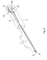
Fig. 1 is a side view, partly in cross-section, showing an endoscope treatment system according to a first embodiment of the present invention; -
Fig. 2 is a perspective view showing an instrument body of the endoscope treatment system according to the first embodiment of the invention; -
Fig. 3 is a side view showing an endoscope body of the endoscope treatment system according to the first embodiment of the invention; -
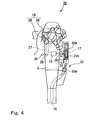
Fig. 4 is a side view partly in cross-section showing the endoscope treatment system according to a second exemplary embodiment useful for understanding the invention; -
Fig. 5 is a perspective view showing the instrument body in the endoscope treatment system according to the second exemplary embodiment useful for understanding the invention; -
Fig. 6 is a side view partly in cross-section showing the endoscope treatment system according to a third exemplary embodiment useful for understanding the invention; -
Fig. 7 is a perspective view showing the instrument body of the endoscope treatment system according to the third exemplary embodiment useful for understanding the invention; -
Fig. 8 is a side view showing the endoscope body in the endoscope treatment system according to the third exemplary embodiment useful for understanding the invention; -
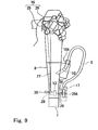
Fig. 9 is a side view partly in cross-section showing the endoscope treatment system according to another exemplary embodiment useful for understanding the invention; and -
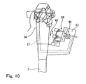
Fig. 10 is a side view partly in cross-section showing the endoscope treatment system according to another exemplary embodiment useful for understanding the invention. - A preferred embodiment of the invention and exemplary embodiments useful for understanding the invention are described below with reference to the accompanying drawings.
- Referring to
Fig. 1 to Fig. 3 , in the embodiment of the present invention, an endoscope treatment system 1 includes aninstrument body 6 including atreatment portion 2 which administers a treatment upon receiving a back-and-forth drive force, an operating wire (transmitting member) 3 connected to thetreatment portion 2 for transmitting the back-and-forth drive force to thetreatment portion 2, and asheath member 5 having theoperating wire 3 fitted therein so that the operating wire can move back-and-forth therein. Anendoscope body 11 capable of receiving theinstrument body 6 inserted therein has achannel 10 for communicating aninsertion portion 7 and anoperating portion 8. A back-and-forthmechanism 12 causes theoperating wire 3 to move back-and-forth with respect to thesheath member 5 in the axial direction, and amotor 13 provided in theoperating portion 8 of theendoscope body 11 drives the back-and-forthmechanism 12. Aninstruction member 15 issues driving instructions to themotor 13 provided on theoperating portion 8. - The
instrument body 6 includes adriving member 16 connected to the proximal end of theoperating wire 3 for moving theoperating wire 3 back-and-forth upon receiving the back-and-forth drive force, abase member 17 which reciprocally accommodates thedriving member 16 therein and which is connected to the distal end of thesheath member 5, and a convertingunit 18 which converts the rotational force of themotor 13 to the back-and-forth drive force. - The back-and-forth
mechanism 12 comprises thedriving member 16 and the convertingunit 18. The convertingunit 18 comprises arotatable roller 21 engaged with arotatable shaft 20 of themotor 13. Theroller 21 is provided with a square orrectangular hole 21A at the center thereof, to receive a square (or rectangular, etc.)shaft 20A which passes through ahole 17A formed on thebase member 17 and which is connected to the revolvingshaft 20 of themotor 13. - The
square shaft 20A is disposed so as to project outwardly from the portion of theoperating portion 8 above aforceps port 10A. - The driving
member 16 is formed as a thin plate, and the distal end thereof is connected to the proximal side of theoperating wire 3, and the proximal end thereof is connected to the outer periphery of theroller 21. Therefore, theoperating wire 3 is connected to the outer periphery of the roller via thedriving member 16 and is capable of being wound therearound. - The
treatment portion 2 includes a pair offorceps operating wire 3. The forceps opens when theoperating wire 3 is moved forward toward the distal end with respect to thesheath member 5, and closes when theoperating wire 3 is retracted. - The
instruction member 15 includes adrive button 25 for activating themotor 13 and astop button 26 for stopping the motor rotation, and is electrically connected to themotor 13 viawiring 27 disposed within the operatingportion 8 of theendoscope body 11. - An
electrical power source 28 energizes themotor 13 via thewiring 27 and achangeover switch 30 changes the direction of rotation of themotor 13. - The
changeover switch 30 can be switched between a "close" position for rotating themotor 13 in the direction of winding the drivingmember 16 on the outer periphery of theroller 21 and an "open" position for rotating the motor in the reverse direction. - Disposed above the
forceps port 10A of the operatingportion 8 is a supportingmember 31 for supporting thebase member 17 to the operatingportion 8 and positioning thesquare shaft 20A and thesquare hole 21A so as to be capable of fitting together when operating theoperating wire 3. - The method of operation and the effects of the endoscope treatment system 1 according to this embodiment are described below.
- Firstly, the operator of the endoscope inserts the
insertion portion 7 of theendoscope body 11 into a body cavity of the patient, and then inserts theinstrument body 6 from thetreatment portion 2 via theforceps port 10A into thechannel 10. Subsequently, thesquare shaft 20A and thesquare hole 21A are fitted to mount thebase member 17 to the supportingmember 31. - When performing a treatment with the
treatment portion 2, theswitch 30 is set to the "open" position, and thedrive button 25 of the operatingportion 8 is pressed to rotate themotor 13. In response, themotor 13 rotates in a direction which delivers the drivingmember 16 from the outer peripheral surface of theroller 21. The rotational force of themotor 13 is transmitted to therotating shaft 20, which then rotates theroller 21 from theshaft 20 through thesquare shaft 20A and thesquare hole 21A. The rotational force transmitted to theroller 21 is converted to a force for moving the drivingmember 16 in the axial direction, and is transmitted to the drivingmember 16. By unwinding theoperating wire 3 off the outer peripheral surface of theroller 21, a forward drive force is transmitted to thetreatment portion 2. As a result, theoperating wire 3 is moved with respect to thesheath member 5, which opens theforceps - Then, the
forceps changeover switch 30 is switched to the "close" position. At this time, since themotor 13 rotates in the reverse direction from the direction described above, theroller 21 also rotates in the reverse direction from the direction described above. - Therefore, the driving
member 16 is wound on the outer peripheral surface of theroller 21 and theoperating wire 3 is retracted with respect to thesheath member 5 to close theforceps - Subsequently, the
stop button 26 is pressed to stop the rotation of themotor 13, and engagement between thesquare shaft 20A and thesquare hole 21A is released to move thebase member 17 apart from the supportingmember 31 so that theinstrument body 6 can be removed from thechannel 10 of theendoscope body 11. - With the endoscope treatment system 1, by operating the
instruction member 15 provided on theendoscope body 11, the operator of theendoscope body 11 can perform the operation of thetreatment portion 2 by his/her hand holding the operatingportion 8 without needing additional assistance. The other hand can be used, for example, for holding theinsertion portion 7, whereby the treatment can be performed easily and reliably. - Also, a simple structure is achieved without making the
endoscope body 11 structurally complicated. - Referring now to
Fig. 4 andFig. 5 , a second exemplary embodiment is described. - The same components as those in the first embodiment described above are represented by the same reference numerals whereby the description thereof is omitted.
- The point of distinction of the second exemplary embodiment over the first embodiment is that a converting
unit 35 of anendoscope treatment system 32 according to the second exemplary embodiment is provided with apinion member 36 which can be connected to thesquare shaft 20A connected to the revolvingshaft 20 via thesquare hole 21A, and arack member 37, which engages the outer peripheral surface of thepinion member 36, is connected to the proximal end of theoperating wire 3 instead of to the drivingmember 16. - The method of operation and effects of the
endoscope treatment system 32 according to this embodiment are now described. - In this exemplary embodiment, as in the first embodiment, an
instrument body 33 is inserted into thechannel 10, and thebase member 17 is supported by the operatingportion 8 by the supportingmember 31. - When performing the treatment, the
changeover switch 30 is set to the "open" position, and thedrive button 25 is pressed to rotate themotor 13. - In this case the rotational force of the
motor 13 is transmitted to theshaft 20, and from theshaft 20, transmitted via thesquare shaft 20A to rotate thepinion member 36. The rotational force transmitted to thepinion member 36 is converted to axial movement of therack member 37 with respect to thebase member 17, thereby moving theoperating wire 3 in the axial direction to transmit the back-and-forth drive force to thetreatment portion 2. In this manner, theoperating wire 3 moves forward with respect to thebase member 17 to open theforceps - To close the
forceps changeover switch 30 is switched to the "close" position. At this time, since themotor 13 rotates in the reverse direction from the direction described above, thepinion member 36 also rotates in the reverse direction from the direction described above. The rotational force transmitted to thepinion member 36 is converted to an axial force for retracting therack member 37 with respect to thebase member 17 when being transmitted to therack member 37 - engaged therewith, thereby moving the
operating wire 3 in the axial direction to transmit the back-and-forth drive force to thetreatment portion 2. Consequently, theoperating wire 3 is retracted with respect to thebase member 17 and theforceps - With the
endoscope treatment system 32, the same effects as in the first embodiment are achieved. - Referring now to
Fig. 6 to Fig. 8 , a third exemplary embodiment is described, in which the same components as those in other preferred and exemplary embodiments described above are represented by the same reference numerals, and the description thereof is therefore omitted. - The difference between the third exemplary embodiment and the first embodiment is that a converting
unit 40 of anendoscope treatment system 38 is disposed within anendoscope body 41. - The proximal side of the
operating wire 3 of aninstrument body 42 is extended so as to project from thesheath member 5. A first engagingmember 45, which is formed into a column-shape, is connected and disposed at the proximal end thereof, and is formed on a part of the outer peripheral surface thereof, with a firstfitting hole 43. A second engagingmember 47, which is formed into a column-shape, is connected and disposed at the proximal end of thesheath member 5, and is also formed on a part of the outer peripheral surface thereof, with a secondfitting hole 46. - Disposed between the first engaging
member 45 and the second engagingmember 47 is ashort tube portion 48 which covers the outer periphery of theoperating wire 3, and which is capable of moving back-and-forth in thesheath member 5, and the proximal end thereof is connected to the first engagingmember 45. - A back-and-
forth mechanism 50 includes a first hookingmember 50A capable of engaging with the firstfitting hole 43, and a second hookingmember 50B capable of engaging with the secondfitting hole 46 in an operatingportion 51 of theendoscope body 41. - The second hooking
member 50B supports thesheath member 5 with the operatingportion 51, by engaging with and holding the second engagingmember 47. - The back-and-
forth mechanism 50 includes therotating shaft 20 connected to themotor 13 and apinion member 52 connected to theshaft 20. The convertingunit 40 is provided with arack member 53 which is connected to the first hookingmember 50A and which can be engaged with the outer peripheral surface of thepinion member 52. - The method of operation and effects of the
endoscope treatment system 38 according to this exemplary embodiment will now be described. After theinsertion portion 7 of theendoscope body 41 is inserted into the body cavity of a patient, thesheath member 5 of theinstrument body 42 is inserted into thechannel 10 from theforceps port 10A. Then, the first hookingmember 50A and the firstfitting hole 43 are fitted to engage the first engagingmember 45 with the first hookingmember 50A, and the second hookingmember 50B and the secondfitting hole 46 are fitted to engage the second engagingmember 47 with the second hookingmember 50B. - When performing a treatment with the
treatment portion 2, themotor 13 is rotated in the same manner as in the other preferred and exemplary embodiments described above. - In this case, the rotational force of the
motor 13 is transmitted to theshaft 20 to rotate thepinion member 52 connected to theshaft 20. The rotational force transmitted to thepinion member 52 is converted to an axial force which moves the first hookingmember 50A back-and-forth in the axial direction, which movement is then transmitted from the firstfitting hole 43 to the first engagingmember 45. - At this time, since the second engaging
member 47 is engaged with the second hookingmember 50B via the secondfitting hole 46, and hence thesheath member 5 is supported by the operatingportion 51, theoperating wire 3 is moved with respect to thesheath member 5 axially. In this manner, theoperating wire 3 is moved forward with respect to thesheath member 5 to open the pair of theforceps - To close the
forceps changeover switch 30 is switched to the "close" position. At this time, since themotor 13 rotates in the reverse direction from the direction described above, thepinion member 52 rotates in the reverse direction from the direction described above to move therack member 53 in the reverse direction. Therefore, by retracting theoperating wire 3 with the first engagingmember 45 with respect to thesheath member 5, theforceps - Subsequently, the
stop button 26 is pressed to stop the rotation of themotor 13. The engagement between the first engagingmember 45 and the first hookingmember 50A and between the second engagingmember 47 and the second hookingmember 50B are released, and theinstrument body 42 is pulled out from thechannel 10 of theendoscope body 41. - With the
endoscope treatment system 38, the same effects as those of the first embodiment are achieved. Since theinstrument body 42 is not provided with the back-and-forth mechanism 50, theinstrument body 42 structure is simpler. - The technical scope of the invention is not limited to the above-described preferred embodiment, and various modifications can be made without departing from the scope of the invention.
- For example, in the above-described embodiment, the
square shaft 20A is disposed above theforceps port 10A on the operatingportion 8 so as to project therefrom, and themotor 13 and the like are also disposed above theforceps port 10A. However, as shown inFig. 9 , a structure such that themotor 13 according to the first embodiment is disposed on the side of theinsertion portion 7 with respect to theforceps port 10A, and the supportingmember 31 is disposed on the side of theforceps port 10A with respect to themotor 13 is also applicable. - In this case, the direction of projection of the
sheath member 5 from thebase member 17 is determined to be a direction from theinsertion portion 7 to the operatingportion 8, thesheath member 5 can be projected from theforceps port 10A by a sufficient length for gripping when moving back-and-forth in thechannel 10. - As shown in
Fig. 10 , a structure in which a supportingportion 57 is provided at a position opposite to an operatingportion 56 with the intermediary of theforceps port 19A, and the convertingunit 40 and the back-and-forth mechanism 50 according to the third embodiment are disposed on the supportingportion 57 is also applicable. - In this case as well, the
instrument body 42 according to the third exemplary embodiment can be used and the endoscope instrument in the related art can be used as well. - In addition, although the
electrical power source 28 is disposed in theoperating portions endoscope bodies - While there has been shown and described what is considered to be preferred embodiments of the invention, it will, of course, be understood that various modifications and changes in form or detail could readily be made without departing from the invention as claimed. It is therefore intended that the invention be not limited to the exact forms described and illustrated, but should be constructed to cover all modifications that may fall within the scope of the appended claims.
Claims (6)
- An endoscope treatment system comprising:an instrument body (6) comprising a treatment portion (2) for performing a treatment in response to a back-and-forth drive force, a transmitting member (3) connected to the treatment portion (2) for transmitting the back-and-forth drive force to the treatment portion (2), and a sheath member (5) in which the transmitting member is fitted to move back-and-forth; andan endoscope body comprising a channel through which the instrument body (6) can be inserted,wherein the endoscope treatment system further comprises:a back-and-forth mechanism (12) for causing the transmitting member (3) to move back-and-forth in an axial direction with respect to the sheath member (5);a driving-power source (13) coupled with the endoscope body for driving the back-and-forth mechanism (12), wherein the driving-power source (13) is a rotational drive source; andan instruction member (15) coupled with the endoscope body for issuing drive instructions to the power source (13),
characterized in that the instrument body (6) comprises:a driving member (16) connected to the transmitting member (3) and operable to cause the transmitting member (3) to move back-and-forth responsive to the back-and-forth drive force from the back-and-forth mechanism (12);a base member (17) including the driving member (16) and connected to the sheath member (5); anda converting mechanism (18) for converting rotational movement of the drive source to the back-and forth drive force,wherein the driving member (16) is a thin plate and the distal end of the driving member (16) is connected to the proximal side of the transmitting member (3) and the converting mechanism (18) comprises a rotatable roller (21) engaged with a rotatable shaft (20A) connected to the drive source, and wherein a proximal end of the driving member (16) is connected to an outer peripheral surface of the roller (21) so as to be wound therearound. - An endoscope treatment system according to Claim 1, wherein the back-and-forth mechanism (12) is disposed in the endoscope body (11).
- An endoscope treatment system according to Claim 1, wherein the back-and-forth mechanism is disposed in the instrument body (6).
- An endoscope treatment system according to Claim 1, wherein the endoscope body comprises an operating portion (8) for operating the endoscope, and a forceps port (10A) connected to the proximal end of the channel and disposed on the operating portion (8); and
wherein the back-and-forth mechanism (12) is disposed at a position opposed to the operating portion (8) with the intermediary of the forceps port (10A). - An endoscope treatment system according to Claim 1, wherein the back-and-forth mechanism (12) is located on a distal side relative to a forceps opening associated with the endoscope body.
- An endoscope treatment system according to Claim 1, wherein the instrument body (6) and the endoscope body are structured to be detachably attachable to one another.
Applications Claiming Priority (2)
| Application Number | Priority Date | Filing Date | Title |
|---|---|---|---|
| JP2004051364A JP2005237659A (en) | 2004-02-26 | 2004-02-26 | Endoscopic treatment system |
| JP2004051364 | 2004-02-26 |
Publications (2)
| Publication Number | Publication Date |
|---|---|
| EP1568305A1 EP1568305A1 (en) | 2005-08-31 |
| EP1568305B1 true EP1568305B1 (en) | 2014-07-02 |
Family
ID=34747500
Family Applications (1)
| Application Number | Title | Priority Date | Filing Date |
|---|---|---|---|
| EP05004145.8A Expired - Fee Related EP1568305B1 (en) | 2004-02-26 | 2005-02-25 | Endoscope treatment system |
Country Status (3)
| Country | Link |
|---|---|
| US (1) | US20050192475A1 (en) |
| EP (1) | EP1568305B1 (en) |
| JP (1) | JP2005237659A (en) |
Families Citing this family (26)
| Publication number | Priority date | Publication date | Assignee | Title |
|---|---|---|---|---|
| AU2005228956B2 (en) | 2004-03-23 | 2011-08-18 | Boston Scientific Limited | In-vivo visualization system |
| JP4727158B2 (en) | 2004-03-23 | 2011-07-20 | オリンパス株式会社 | Endoscope system |
| US7922654B2 (en) | 2004-08-09 | 2011-04-12 | Boston Scientific Scimed, Inc. | Fiber optic imaging catheter |
| US11819192B2 (en) | 2004-03-23 | 2023-11-21 | Boston Scientific Scimed, Inc. | In-vivo visualization system |
| US20060252993A1 (en) * | 2005-03-23 | 2006-11-09 | Freed David I | Medical devices and systems |
| EP1927311B1 (en) * | 2005-09-22 | 2013-01-09 | Olympus Corporation | Endoscope system |
| JP5121132B2 (en) * | 2005-11-02 | 2013-01-16 | オリンパスメディカルシステムズ株式会社 | Endoscope system and operation assist device for endoscope |
| US7524284B2 (en) * | 2006-02-06 | 2009-04-28 | Olympus Medical Systems Corp. | Endoscopy system |
| US8062211B2 (en) * | 2006-06-13 | 2011-11-22 | Intuitive Surgical Operations, Inc. | Retrograde instrument |
| US7691054B2 (en) * | 2006-06-23 | 2010-04-06 | Olympus Medical Systems Corporation | Endoscope system, treatment instrument cartridge, and storage case |
| US7488319B2 (en) * | 2006-07-06 | 2009-02-10 | Yates Leroy L | Resecting device |
| US7582055B2 (en) * | 2006-08-09 | 2009-09-01 | Olympus Medical Systems Corp. | Endoscope system |
| ATE542470T1 (en) | 2006-09-11 | 2012-02-15 | Storz Karl Endovision Inc | SYSTEM FOR A HYSTEROSCOPE WITH INTEGRATED INSTRUMENTS |
| JP4914736B2 (en) * | 2007-02-14 | 2012-04-11 | オリンパスメディカルシステムズ株式会社 | Endoscope system |
| JP4648365B2 (en) * | 2007-07-23 | 2011-03-09 | オリンパス株式会社 | Endoscopic treatment system |
| US8529554B2 (en) * | 2007-09-05 | 2013-09-10 | Olympus Medical Systems Corp. | Treatment instrument operation unit and medical system with treatment instrument operation unit |
| US20090137872A1 (en) * | 2007-11-27 | 2009-05-28 | Tyco Healthcare Group Lp | Method and Apparatus for Controlling Endoscopic Instruments |
| KR101750628B1 (en) * | 2015-12-14 | 2017-06-26 | 한국과학기술원 | An apparatus for surgery comprising a surgical arm attached to the endoscope and a surgery system comprising thereof |
| WO2018042899A1 (en) | 2016-08-31 | 2018-03-08 | オリンパス株式会社 | Advancement/retraction assisting tool for treatment tool, and endoscope system |
| CN110809427B (en) | 2017-07-18 | 2022-03-18 | 富士胶片株式会社 | Endoscope with a detachable handle |
| EP3656278B1 (en) | 2017-07-18 | 2021-07-21 | FUJIFILM Corporation | Endoscope |
| WO2019017114A1 (en) | 2017-07-18 | 2019-01-24 | 富士フイルム株式会社 | Endoscope |
| CN110809428B (en) | 2017-07-18 | 2022-05-24 | 富士胶片株式会社 | Endoscope with a detachable handle |
| JP6731554B2 (en) | 2017-07-18 | 2020-07-29 | 富士フイルム株式会社 | Endoscope |
| CN111065313A (en) * | 2017-09-28 | 2020-04-24 | 富士胶片株式会社 | Endoscope with a detachable handle |
| FR3103696A1 (en) | 2019-12-03 | 2021-06-04 | Institut Hospitalo-Universitaire De Chirurgie Mini-Invasive Guidee Par L'image | Motorized actuation module of an endoscopic instrument |
Family Cites Families (22)
| Publication number | Priority date | Publication date | Assignee | Title |
|---|---|---|---|---|
| JPS4710474Y1 (en) * | 1968-05-24 | 1972-04-18 | ||
| JPS6048011A (en) * | 1983-08-27 | 1985-03-15 | Olympus Optical Co Ltd | Endoscope device |
| US5431645A (en) * | 1990-05-10 | 1995-07-11 | Symbiosis Corporation | Remotely activated endoscopic tools such as endoscopic biopsy forceps |
| JPH0654801A (en) | 1992-08-04 | 1994-03-01 | Olympus Optical Co Ltd | Endoscope with multifunction treating implement |
| US5735861A (en) * | 1995-09-06 | 1998-04-07 | Wilson-Cook Medical, Inc. | Channel mounted activating mechanism for an endoscopic ligator |
| US5779623A (en) * | 1993-10-08 | 1998-07-14 | Leonard Medical, Inc. | Positioner for medical instruments |
| JPH08224241A (en) * | 1995-02-22 | 1996-09-03 | Olympus Optical Co Ltd | Medical manipulator |
| JP3500228B2 (en) * | 1995-06-21 | 2004-02-23 | オリンパス株式会社 | Endoscope treatment instrument insertion / extraction device |
| JP3810177B2 (en) * | 1997-03-25 | 2006-08-16 | オリンパス株式会社 | Endoscope system |
| US6059719A (en) * | 1997-08-06 | 2000-05-09 | Olympus Optical Co., Ltd. | Endoscope system |
| IL123646A (en) * | 1998-03-11 | 2010-05-31 | Refael Beyar | Remote control catheterization |
| DE29808180U1 (en) * | 1998-05-06 | 1998-07-23 | Stm Medtech Starnberg | Drive device for slip hose system |
| JP4175693B2 (en) | 1998-06-15 | 2008-11-05 | オリンパス株式会社 | Endoscope treatment instrument insertion / extraction device |
| JP2000287985A (en) * | 1999-04-07 | 2000-10-17 | Olympus Optical Co Ltd | Abscission instrument for surgery |
| JP2000342516A (en) * | 1999-06-03 | 2000-12-12 | Asahi Optical Co Ltd | Endoscope for treating and treating tool |
| DK200001852A (en) * | 1999-12-14 | 2001-06-15 | Asahi Optical Co Ltd | Manipulation section for an endoscopic treatment instrument |
| US6817973B2 (en) * | 2000-03-16 | 2004-11-16 | Immersion Medical, Inc. | Apparatus for controlling force for manipulation of medical instruments |
| EP1188517A1 (en) * | 2000-09-14 | 2002-03-20 | Storz-Endoskop GmbH | Removable tool insert and endoscopic processing apparatus |
| JP2003111769A (en) | 2001-10-03 | 2003-04-15 | Pentax Corp | Endo-therapy accessory system for endoscope |
| JP2004049891A (en) * | 2002-05-29 | 2004-02-19 | Olympus Corp | Endoscope apparatus |
| JP5160050B2 (en) * | 2006-06-07 | 2013-03-13 | オリンパスメディカルシステムズ株式会社 | Endoscopic treatment tool |
| US7582055B2 (en) * | 2006-08-09 | 2009-09-01 | Olympus Medical Systems Corp. | Endoscope system |
-
2004
- 2004-02-26 JP JP2004051364A patent/JP2005237659A/en active Pending
-
2005
- 2005-02-25 US US11/067,266 patent/US20050192475A1/en not_active Abandoned
- 2005-02-25 EP EP05004145.8A patent/EP1568305B1/en not_active Expired - Fee Related
Also Published As
| Publication number | Publication date |
|---|---|
| JP2005237659A (en) | 2005-09-08 |
| US20050192475A1 (en) | 2005-09-01 |
| EP1568305A1 (en) | 2005-08-31 |
Similar Documents
| Publication | Publication Date | Title |
|---|---|---|
| EP1568305B1 (en) | Endoscope treatment system | |
| US7708685B2 (en) | Operating instrument system for endoscope | |
| US9706907B2 (en) | Remote endoscope handle manipulation | |
| EP1568306B1 (en) | Endoscope | |
| EP2247229B1 (en) | Remote endoscope handle manipulation | |
| EP2022433A1 (en) | Endoscope treatment system | |
| WO2010101401A2 (en) | Surgical instrument | |
| EP3025669A1 (en) | Medical manipulator | |
| US11918186B2 (en) | Endoscopic device with USB port and powered accessories | |
| US20190142247A1 (en) | Endoscope and Treatment Tool Drive Module | |
| EP2401952A1 (en) | Endoscope apparatus | |
| CN217138147U (en) | Surgical instrument and surgical robot | |
| JP3980926B2 (en) | Surgical tools | |
| JP4500310B2 (en) | Insertion device and endoscope system | |
| CN113164217A (en) | Wearable surgical mechanical arm | |
| JP2005328968A (en) | Endoscope processing system | |
| JP3504392B2 (en) | Endoscope treatment instrument insertion / extraction device | |
| JP3231471B2 (en) | Endoscope | |
| CN218338520U (en) | Endoscopic surgical device | |
| CN218338515U (en) | Surgical instrument assembly, surgical instrument control unit and endoscopic surgical device | |
| US20230104573A1 (en) | Control system for a colonoscope | |
| JP2005323893A (en) | Endoscope treatment system | |
| JP2005349090A (en) | Treatment tool for endoscope | |
| CN116269573A (en) | Surgical instrument and surgical robot | |
| JP2005334332A (en) | Endoscope and endoscope treatment system |
Legal Events
| Date | Code | Title | Description |
|---|---|---|---|
| PUAI | Public reference made under article 153(3) epc to a published international application that has entered the european phase |
Free format text: ORIGINAL CODE: 0009012 |
|
| AK | Designated contracting states |
Kind code of ref document: A1 Designated state(s): AT BE BG CH CY CZ DE DK EE ES FI FR GB GR HU IE IS IT LI LT LU MC NL PL PT RO SE SI SK TR |
|
| AX | Request for extension of the european patent |
Extension state: AL BA HR LV MK YU |
|
| 17P | Request for examination filed |
Effective date: 20050829 |
|
| AKX | Designation fees paid |
Designated state(s): DE FR GB IE |
|
| 17Q | First examination report despatched |
Effective date: 20071022 |
|
| GRAP | Despatch of communication of intention to grant a patent |
Free format text: ORIGINAL CODE: EPIDOSNIGR1 |
|
| INTG | Intention to grant announced |
Effective date: 20140210 |
|
| GRAS | Grant fee paid |
Free format text: ORIGINAL CODE: EPIDOSNIGR3 |
|
| GRAA | (expected) grant |
Free format text: ORIGINAL CODE: 0009210 |
|
| AK | Designated contracting states |
Kind code of ref document: B1 Designated state(s): DE FR GB IE |
|
| REG | Reference to a national code |
Ref country code: GB Ref legal event code: FG4D |
|
| REG | Reference to a national code |
Ref country code: IE Ref legal event code: FG4D |
|
| REG | Reference to a national code |
Ref country code: DE Ref legal event code: R096 Ref document number: 602005044053 Country of ref document: DE Effective date: 20140807 |
|
| REG | Reference to a national code |
Ref country code: DE Ref legal event code: R097 Ref document number: 602005044053 Country of ref document: DE |
|
| PLBE | No opposition filed within time limit |
Free format text: ORIGINAL CODE: 0009261 |
|
| STAA | Information on the status of an ep patent application or granted ep patent |
Free format text: STATUS: NO OPPOSITION FILED WITHIN TIME LIMIT |
|
| 26N | No opposition filed |
Effective date: 20150407 |
|
| GBPC | Gb: european patent ceased through non-payment of renewal fee |
Effective date: 20150225 |
|
| REG | Reference to a national code |
Ref country code: IE Ref legal event code: MM4A |
|
| REG | Reference to a national code |
Ref country code: FR Ref legal event code: ST Effective date: 20151030 |
|
| PG25 | Lapsed in a contracting state [announced via postgrant information from national office to epo] |
Ref country code: IE Free format text: LAPSE BECAUSE OF NON-PAYMENT OF DUE FEES Effective date: 20150225 Ref country code: GB Free format text: LAPSE BECAUSE OF NON-PAYMENT OF DUE FEES Effective date: 20150225 |
|
| PG25 | Lapsed in a contracting state [announced via postgrant information from national office to epo] |
Ref country code: FR Free format text: LAPSE BECAUSE OF NON-PAYMENT OF DUE FEES Effective date: 20150302 |
|
| PGFP | Annual fee paid to national office [announced via postgrant information from national office to epo] |
Ref country code: DE Payment date: 20190219 Year of fee payment: 15 |
|
| REG | Reference to a national code |
Ref country code: DE Ref legal event code: R119 Ref document number: 602005044053 Country of ref document: DE |
|
| PG25 | Lapsed in a contracting state [announced via postgrant information from national office to epo] |
Ref country code: DE Free format text: LAPSE BECAUSE OF NON-PAYMENT OF DUE FEES Effective date: 20200901 |