EP1567983B1 - Verfahren zur automatischen definition interessierender regionen für abgleich und visualisierung forensischer bilder - Google Patents
Verfahren zur automatischen definition interessierender regionen für abgleich und visualisierung forensischer bilder Download PDFInfo
- Publication number
- EP1567983B1 EP1567983B1 EP03767326.6A EP03767326A EP1567983B1 EP 1567983 B1 EP1567983 B1 EP 1567983B1 EP 03767326 A EP03767326 A EP 03767326A EP 1567983 B1 EP1567983 B1 EP 1567983B1
- Authority
- EP
- European Patent Office
- Prior art keywords
- image
- interest
- angle
- mask
- region
- Prior art date
- Legal status (The legal status is an assumption and is not a legal conclusion. Google has not performed a legal analysis and makes no representation as to the accuracy of the status listed.)
- Expired - Lifetime
Links
Images


Classifications
-
- G—PHYSICS
- G06—COMPUTING OR CALCULATING; COUNTING
- G06V—IMAGE OR VIDEO RECOGNITION OR UNDERSTANDING
- G06V10/00—Arrangements for image or video recognition or understanding
- G06V10/40—Extraction of image or video features
- G06V10/50—Extraction of image or video features by performing operations within image blocks; by using histograms, e.g. histogram of oriented gradients [HoG]; by summing image-intensity values; Projection analysis
- G06V10/507—Summing image-intensity values; Histogram projection analysis
Definitions
- the invention relates to detecting regions of interest in images. More specifically, it relates to automatically detecting lined regions contained inside forensic digital images.
- An object of the present invention is to extract better quality signatures from images. Another object of the present invention is to speed up the correlation process for ballistic image comparisons. Yet another object of the invention is to remove the need to have a firearms examiner participate in the correlation process for ballistic image comparisons.
- the invention is defined in claims 1, 21, and 31. Optional features are indicated in the dependent claims. A mask is created with the property that a value of zero is assigned to each pixel position with an orientation angle above a predetermined threshold and is assigned to 1 otherwise.
- a dominant orientation angle in the image is determined and a value of zero is assigned to each pixel position with an orientation angle which varies for the dominant angle by more than a predetermined threshold.
- the mask may be created and applied separately for each dominant angle and a signature is calculated for each image having a separate mask applied.
- the image is separated into a plurality of vertical bands, wherein identifying a region of interest, creating and applying a mask, aligning horizontally elements, and calculating a signature is done for each of the plurality of vertical bands.
- the plurality of vertical bands can also be based on groupings of similar orientation angles.
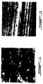
- Figure 1A is a very noisy image that comprises barely any lines.
- Figure 1B is a good quality image with clear lines having a constant orientation.
- a signature based on the image in figure 1A is practically useless while a signature based on the image in figure 1B is very significant. Based on this principle, it is very important to detect regions having a high signal-to-noise ratio. These regions can then be eliminated from the image and won't impact the signature extracted from the image.
- a mask can be created, also called an anisotropic mask, that eliminates the noisy regions before the signature is extracted.
- the mask is actually an image of the same size as the original image wherein the pixels that correspond to the noisy pixels in the original image are set to zero and the pixels with the clear lines are set to one.
- a first module has the principal responsibility of the estimation of the local orientation at each pixel position. This could be accomplished by many different techniques such as texture analysis, Gabor filters, Hough transform or the orientation tensor to name a few. We choose the orientation tensor for its ease of implementation.
- Orilmage that has the same dimension as the original image but where the value associated with each pixel position is the orientation angle comprised between [-90°, 90°].
- the best global alignment angle can easily be found based on the histogram of the orientation image.
- the simplest choice is just the angle for which the histogram attains its maximum value. We found that in practice, this method gives good results. Other more precise techniques could also be used like finding the best Gaussian distribution fitting the histogram and taking the mean of this Gaussian as the best angle.
- Signatures can then be created for all bands and these signatures will be more precise than if we had created only one signature based on a globally aligned image. Therefore, the chances of matching two bullets fired from the same gun are increased.
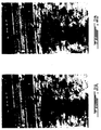
- Figure 2A is an example of an image with regions that comprise clear lines and regions that are very noisy.
- Figure 2B is the same image once the noisy regions have been masked. The pixels in the darkened areas were set to a value of zero in order to be disregarded when the signature is extracted.
- Another embodiment of the present invention consists in eliminating random striation marks that are clearly in an opposite direction from the majority of lines in an image.
- Figure 3A shows a line intersecting a big part of the other lines and going in an opposite direction. These random marks occur sometimes and are not reproducible. They affect the quality of the image signature necessary for correlation.
- the present system can detect a dominant orientation of the striation marks and mask regions having orientations that differ from the dominant orientation.
- the majority of the lines are oriented at 3.5° with respect to the horizontal axis.
- the random mark is a scratch oriented at -75° with respect to the horizontal axis.
- the image in figure 3B has been masked to eliminate all pixels with an orientation that is not within 3.0° of the dominant orientation.
- the threshold tolerance such as 3.0° in this case, can be chosen by the user or can be pre-programmed into the system.
- FIG. 4A is the image with a first mask applied while figure 4C is the image with a second mask applied.
- Detecting if more than one main orientation is present in the image can be done in several ways. For example, by computing the histogram of the orientation image (or one of its sub-region), we can estimate the number of main orientations present. We use a simple criteria based on the number and distribution of the histogram's local maximum. If more than one local maximum exist and they are separated by at least 3°, we conclude that each of these local maximum corresponds to one dominant orientation. Alternatively, if more than one main orientation is present in the image and these orientations are different enough, we can use create a mask that permits us to select only the regions in the image that have an orientation within a given tolerance of a given angle to select the regions corresponding to each main orientation. This would permit us to create signatures that are specific to each of these orientations.
- G is a 2x2 symmetric positive semi definite matrix whose eigenvalues ⁇ 1 ⁇ ⁇ 2 are positives.
- A 1 ⁇ ⁇ 2 / ⁇ 1 from the eigenvalues ⁇ 1 , ⁇ 2 of G.
- ⁇ 2 / ⁇ 1 lies in the interval [0,1]
- A also lies in the interval [0,1].
- a value of zero for A indicates a perfectly isotropic neighborhood where a value of one indicates a perfectly anisotropic neighborhood. In practice, the value of A is almost always somewhere between 0.1 and 0.9.
- the first step consists in identifying at least one region of interest within the image by determining local orientation information comprising elements useful for the specific identification purposes 10.
- the elements are characteristic lines and the characteristic lines are striation marks on a bullet or a bullet casing.
- the pixel positions are assigned an orientation angle.
- the second step comprises creating and applying a mask for the image wherein only the identified regions of interest are exposed 11. If the orientation angle is above a predetermined threshold, the value of the pixel is set to zero.
- the predetermined threshold can be entered by a user. It can also be an angle calculated by the system as a function of the predominant angle.
- the third step comprises extracting a signature for the image by taking into account the regions of interest that were left exposed by the mask and disregarding the regions that were blocked from the image.
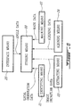
- FIG. 6 is a preferred embodiment for the apparatus of the present invention.
- Storing means 20 are used to store an image.
- Identifying means 21 are for identifying at least one region of interest within the image by determining local orientation information at pixel positions in the image, the region of interest comprising elements useful for the specific identification purposes.
- the elements can be characteristic lines which are striation marks from a bullet or a bullet casing.
- Local orientation data is sent from the identifying means 21 to the storing means 20.
- Masking means 22 are then used to create and apply a mask for the image, wherein only the region of interest is exposed.
- the mask data is sent from the masking means 22 to the storing means 20.
- Extracting means 23 are used to extract a signature for the image, taking into account the region of interest exposed by the mask.
- the image signature data is sent from the extracting means 23 to the storing means 20.
- Aligning means 24 may also be present in the apparatus to align horizontally the elements that are present in the region of interest, transferring aligning data from the aligning means 24 to the storing means 20.
- Interface means are also used for a user to enter a value for a predetermined threshold angle and the angle data is transferred to the storing means 20.
- the identifying means 21 may further comprise means for assigning an orientation angle at each pixel position in the image, means for separating the image into a plurality of vertical bands, wherein the vertical bands are based on groupings of similar orientation angles, and means for detecting lined regions within the image.
- the identifying means may also further comprise computing means for computing three different components of a structure tensor for each pixel in said image, image anisotropy means for creating an anisotropy image wherein each of said pixel is given an anisotropy value computed from said structure tensor, and anisotropy mask means for creating an anisotropy mask from said anisotropy image wherein pixels whose value is greater than a given threshold are set to 1 and pixels whose value is less than a given threshold are set to 0.
- the masking means 22 may further comprise means for assigning a value to zero for each pixel position with an orientation angle above a predetermined threshold, means for determining a dominant orientation angle in the image and assigning a value of zero to the pixel positions with an orientation angle with varies from the dominant angle by more than a predetermined threshold, means for creating and applying separate masks for each dominant angle, and means for calculation the predetermined threshold angle as a function of the predominant angle.
- the extracting means 23 may also comprise means for extracting a signature for each image having a separate mask applied, in the case where more than one mask is applied for one image.
Landscapes
- Engineering & Computer Science (AREA)
- Physics & Mathematics (AREA)
- General Physics & Mathematics (AREA)
- Multimedia (AREA)
- Theoretical Computer Science (AREA)
- Image Analysis (AREA)
Claims (30)
- Verfahren für ein automatisiertes System zum Extrahieren einer qualitativ hochwertigen Signatur aus einem Bild, das Gebiete hat, die nicht relevant sind für spezifische Identifizierungszwecke, die zu irreführenden Bildsignaturen führen können, welches Verfahren umfasst:Identifizieren wenigstens einer interessierenden Region in dem Bild durch Bestimmen lokaler Orientierungsinformation an Pixelpositionen in dem Bild und weiterhin Zuweisen eines Orientierungswinkels zu jeder dieser Pixelpositionen in dem Bild, wobei die wenigstens eine interessierende Region Elemente enthält, die für spezifische Identifizierungszwecke nützlich sind, wobei diese Identifizierung einer interessierenden Region weiterhin die Detektion von linierten Regionen innerhalb dieses Bildes einschließt;Erzeugen und Anwenden einer Maske für das Bild, wobei nur die genannte wenigstens eine interessierende Region freigelegt wird; undExtrahieren einer Signatur für dieses Bild aus dieser wenigstens einen interessierenden Region, die durch die Maske freigelegt ist, dadurch gekennzeichnet, dassdas Extrahieren einer Signatur das Zuweisen eines eindimensionalen Signals zu dem genannten Bild einschließt,wobei das genannte Erzeugen und Anwenden einer Maske die Bestimmung eines dominanten Orientierungswinkels in dem Bild und das Zuweisen eines Wertes von null zu jeder der Pixelpositionen mit einem Orientierungswinkel, der um mehr als einen vorgegebenen Schwellenwert von dem genannten dominanten Winkel abweicht, einschließt.
- Verfahren nach Anspruch 1, mit dem weiteren Schritt der horizontalen Ausrichtung der in der genannten wenigsten einen interessierenden Region vorhandenen Elemente.
- Verfahren nach Anspruch 1, bei dem die Maske für jeden dominanten Orientierungswinkel getrennt erzeugt und angewandt wird.
- Verfahren nach Anspruch 3, bei dem das Berechnen einer Signatur weiterhin das Berechnen einer Signatur für jedes Bild einschließt, auf das eine separate Maske angewandt wurde.
- Verfahren nach Anspruch 1, bei dem die Elemente charakteristische Linien sind.
- Verfahren nach Anspruch 5, bei dem die charakteristischen Linien Streifenmarken eines Geschosses oder einer Geschosshülse sind.
- Verfahren nach Anspruch 1, weiterhin umfassend das Aufteilen des Bildes in eine Vielzahl vertikaler Bänder, wobei das Identifizieren einer interessierenden Region, das Erzeugen und Anwenden einer Maske, das horizontale Ausrichten der Elemente und das Berechnen einer Signatur für jedes Band aus der Vielzahl der vertikalen Bänder erfolgt.
- Verfahren nach Anspruch 1, weiterhin umfassend das Aufteilen des Bildes in eine Vielzahl vertikaler Bänder auf der Basis von Gruppierungen von ähnlichen Orientierungswinkeln, wobei das Identifizieren einer interessierenden Region, das Erzeugen und Anwenden einer Maske, das horizontale Ausrichten von Elementen und das Berechnen einer Signatur für jedes Band aus der Vielzahl der vertikalen Bänder erfolgt.
- Verfahren nach Anspruch 1, bei dem der vorgegebene Schwellenwert ein von einem Benutzer eingegebener Winkel ist.
- Verfahren nach Anspruch 1, bei dem der vorbestimmte Schwellenwert ein als Funktion des genannten prädominanten Winkels berechneter Winkel ist.
- Verfahren nach Anspruch 1, bei dem das Zuweisen eines Orientierungswinkels zu jeder Pixelposition weiterhin die Verwendung eine Hough-Transformation einschließt.
- Verfahren nach Anspruch 1, bei dem das Zuweisen eines Orientierungswinkels zu jeder Pixelposition weiterhin die Verwendung eines Orientierungstensors einschließt.
- Verfahren nach Anspruch 1, bei dem das Bestimmen eines dominanten Winkels weiterhin das Erstellen eines Histogramms des Bildes und das Identifizieren eines Winkels, bei dem dieses Histogramm seinen Maximalwert erreicht, als den dominanten Winkel einschließt.
- Verfahren nach Anspruch 13, bei dem die Existenz von mehr als einem dominanten Winkel angenommen wird, wenn das Histogramm mehr als ein lokales Maximum enthält und diese lokalen Maxima um wenigstens drei Grad verschieden sind.
- Verfahren nach Anspruch 1, bei dem das Detektieren von linierten Regionen umfasst: Berechnen dreier verschiedener Komponenten eines Strukturtensors für jedes Pixel in dem Bild; Erzeugen eines Anisotropiebildes, bei dem jedem dieser Pixel ein Anisotropiewert gegeben wird, der aus dem Strukturtensor berechnet wird; Erzeugen einer Anisotropiemaske aus dem Anisotropiebild, wobei Pixel, deren Wert größer ist als ein gegebener Schwellenwert auf 1 gesetzt werden und Pixel, deren Wert kleiner als ein gegebener Schwellenwert ist, auf 0 gesetzt werden.
- Verfahren nach Anspruch 15, bei der Anisotropiewert in dem Intervall [0, 1] liegt.
- Verfahren nach Anspruch 16, bei dem der vorgegebene Schwellenwert 0,7 ist.
- Verfahren nach Anspruch 15, bei dem die drei verschiedenen Komponenten partielle Ableitungen einer Gauss-geglätteten Version des Bildes sind.
- Verfahren nach Anspruch 15, bei dem der Strukturtensor eine symmetrische positiv semidefinite 2x2 Matrix ist, deren Eigenwerte positiv sind.
- Vorrichtung für ein automatisiertes System zum Extrahieren einer qualitativ hochwertigen Signatur aus einem Bild, das Gebiete hat, die nicht relevant sind für spezifische Identifizierungszwecke, die zu irreführenden Bildsignaturen führen können, welche Vorrichtung aufweist:Speichermittel zum Speichern eines Bildes;Identifizierungsmittel zum Identifizieren wenigstens einer interessierenden Region in dem Bild durch Bestimmen lokaler Orientierungsinformation an Pixelpositionen in dem Bild und weiterhin Zuweisen eines Orientierungswinkels zu jeder dieser Pixelpositionen in dem Bild, wobei die genannte wenigstens eine interessierende Region Elemente enthält, die für die genannten spezifischen Identifizierungszwecke nützlich sind, wobei die Identifizierungsmittel weiterhin Mittel zum Detektieren linierter Regionen in dem Bild umfassen;Maskierungsmittel zum Erzeugen und Anwenden einer Maske auf das Bild, bei der die genannte wenigstens eine interessierende Region freigelegt wird; undExtraktionsmittel zum Extrahieren einer Signatur für das Bild aus der genannten wenigstens einen interessierenden Region, die durch die Maske freigelegt ist;dadurch gekennzeichnet, dass die Extraktionsmittel Mittel zum Zuweisen eines eindimensionalen Signals zu dem genannten Bild aufweisen und die Maskierungsmittel Mittel zum Bestimmen eines dominanten Orientierungswinkels in dem Bild und zum Zuweisen eines Wertes von null zu jeder der Pixelpositionen mit einem Orientierungswinkel, der um mehr als einen vorgegebenen Schwellenwert von dem dominanten Winkel abweicht, einschließen.
- Vorrichtung nach Anspruch 20, mit Ausrichtmitteln zum horizontalen Ausrichten der genannten Elemente, die in der genannten mindestens einen interessierenden Region vorhanden sind.
- Vorrichtung nach Anspruch 21, bei der die Maskierungsmittel weiterhin Mittel zum Erzeugen und Anwenden getrennter Masken für jeden der genannten dominanten Orientierungswinkel umfassen.
- Vorrichtung nach Anspruch 22, bei der die genannten Extraktionsmittel weiterhin Mittel zum Extrahieren einer Signatur für jedes Bild umfassen, auf das eine separate Maske angewandt wurde.
- Vorrichtung nach Anspruch 20, bei der die Identifizierungsmittel weiterhin Separiermittel zum Separieren des genannten Bildes in eine Vielzahl vertikaler Bänder aufweisen.
- Vorrichtung nach Anspruch 24, bei der die genannten Separiermittel weiterhin Mittel zum Separieren des Bildes in eine Vielzahl vertikaler Bänder auf der Grundlage von Gruppierungen von ähnlichen Orientierungswinkeln umfassen.
- Vorrichtung nach Anspruch 20, mit Schnittstellenmitteln zur Eingabe eines Wertes für den genannten vorbestimmten Schwellenwert durch einen Benutzer.
- Vorrichtung nach Anspruch 20, bei der die Maskierungsmittel weiterhin Rechenmittel zum Berechnen des genannten vorbestimmten Schwellenwertes für den Winkel als eine Funktion des genannten prädominanten Winkels umfassen.
- Vorrichtung nach Anspruch 20, bei der Identifizierungsmittel weiterhin aufweisen:Rechenmittel zum Berechnen dreier verschiedener Komponenten eines Strukturtensors für jedes Pixel in dem Bild;Bildanisotropiemittel zum Erzeugen eines Anisotropiebildes, bei dem jedem der genannten Pixel ein Anisotropiewert gegeben wird, der aus dem Strukturtensor berechnet wird; undAnisotropiemaskierungsmittel zum Erzeugen einer Anisotropiemaske aus dem Anisotropiebild, wobei Pixel, deren Wert größer ist als ein gegebener Schwellenwert auf 1 gesetzt werden und Pixel, deren Wert kleiner ist als ein gegebener Schwellenwert, auf 0 gesetzt werden.
- Computerlesbarer Speicher zum Speichern programmierbarer Instruktionen zum Gebrauch bei der Ausführung des Verfahrens nach einem der Ansprüche 1 bis 19 in einem Computer.
- Computerdatensignal in einer Trägerwelle, mit Daten, die aus einem Verfahren für ein automatisiertes System zum Extrahieren einer qualitativ hochwertigen Signatur aus einem Bild resultieren, das Gebiete hat, die nicht relevant sind für spezifische Identifizierungszwecke, die zu irreführenden Bildsignaturen führen können, welches Verfahren umfasst:Identifizieren wenigstens einer interessierenden Region in dem Bild durch Bestimmen lokaler Orientierungsinformation an Pixelpositionen in dem Bild und weiterhin Zuweisen eines Orientierungswinkels zu jeder dieser Pixelpositionen in dem Bild, wobei die wenigstens eine interessierende Region Elemente enthält, die für spezifische Identifizierungszwecke nützlich sind, wobei diese Identifizierung einer interessierenden Region weiterhin die Detektion von linierten Regionen innerhalb dieses Bildes einschließt;Erzeugen und Anwenden einer Maske für das Bild, wobei nur die genannte wenigstens eine interessierende Region freigelegt wird; undExtrahieren einer Signatur für dieses Bild aus dieser wenigstens einen interessierenden Region, die durch die Maske freigelegt ist,dadurch gekennzeichnet, dass das genannte Erzeugen und Anwenden einer Maske die Bestimmung eines dominanten Orientierungswinkels in dem Bild und das Zuweisen eines Wertes von null zu jeder der Pixelpositionen mit einem Orientierungswinkel, der um mehr als einen vorgegebenen Schwellenwert von dem genannten dominanten Winkel abweicht, einschließt;und das Extrahieren einer Signatur das Zuweisen eines eindimensionalen Signals zu dem genannten Bild einschließt.
Applications Claiming Priority (3)
| Application Number | Priority Date | Filing Date | Title |
|---|---|---|---|
| US30809502A | 2002-12-03 | 2002-12-03 | |
| US308095 | 2002-12-03 | ||
| PCT/CA2003/001894 WO2004051570A2 (en) | 2002-12-03 | 2003-12-03 | Method for automatically defining regions of interest for matching and visualizing forensic images |
Publications (2)
| Publication Number | Publication Date |
|---|---|
| EP1567983A2 EP1567983A2 (de) | 2005-08-31 |
| EP1567983B1 true EP1567983B1 (de) | 2016-05-25 |
Family
ID=32467800
Family Applications (1)
| Application Number | Title | Priority Date | Filing Date |
|---|---|---|---|
| EP03767326.6A Expired - Lifetime EP1567983B1 (de) | 2002-12-03 | 2003-12-03 | Verfahren zur automatischen definition interessierender regionen für abgleich und visualisierung forensischer bilder |
Country Status (5)
| Country | Link |
|---|---|
| US (1) | US7565014B2 (de) |
| EP (1) | EP1567983B1 (de) |
| AU (1) | AU2003291868A1 (de) |
| CA (1) | CA2505194C (de) |
| WO (1) | WO2004051570A2 (de) |
Families Citing this family (5)
| Publication number | Priority date | Publication date | Assignee | Title |
|---|---|---|---|---|
| US8073248B2 (en) * | 2007-06-08 | 2011-12-06 | Apple Inc. | Automatic detection of calibration charts in images |
| US8326048B2 (en) * | 2007-10-04 | 2012-12-04 | Microsoft Corporation | Geo-relevance for images |
| US8477188B2 (en) * | 2009-10-14 | 2013-07-02 | Harris Corporation | Surveillance system for transcoding surveillance image files while retaining geospatial metadata and associated methods |
| FR3026211B1 (fr) * | 2014-09-19 | 2017-12-08 | Univ Aix Marseille | Procede d'identification de l'anisotropie de la texture d'une image numerique |
| FR3059128B1 (fr) * | 2016-11-24 | 2020-01-10 | Universite D'aix-Marseille | Procede de caracterisation de l'anisotropie de la texture d'une image numerique |
Family Cites Families (4)
| Publication number | Priority date | Publication date | Assignee | Title |
|---|---|---|---|---|
| US5390108A (en) * | 1991-05-24 | 1995-02-14 | Forensic Technology Wai Inc. | Computer automated bullet analysis apparatus |
| JP3403875B2 (ja) * | 1995-10-16 | 2003-05-06 | 大日本スクリーン製造株式会社 | 三次元計測方法および表示方法、ならびに三次元計測装置 |
| US6965645B2 (en) * | 2001-09-25 | 2005-11-15 | Microsoft Corporation | Content-based characterization of video frame sequences |
| JP4053345B2 (ja) * | 2002-04-25 | 2008-02-27 | シャープ株式会社 | 画像処理方法および画像処理装置、それを備える画像形成装置ならびにプログラムおよび記録媒体 |
-
2003
- 2003-12-03 EP EP03767326.6A patent/EP1567983B1/de not_active Expired - Lifetime
- 2003-12-03 WO PCT/CA2003/001894 patent/WO2004051570A2/en not_active Ceased
- 2003-12-03 CA CA2505194A patent/CA2505194C/en not_active Expired - Lifetime
- 2003-12-03 AU AU2003291868A patent/AU2003291868A1/en not_active Abandoned
-
2005
- 2005-05-31 US US11/140,090 patent/US7565014B2/en active Active
Also Published As
| Publication number | Publication date |
|---|---|
| EP1567983A2 (de) | 2005-08-31 |
| WO2004051570A3 (en) | 2004-12-29 |
| WO2004051570A2 (en) | 2004-06-17 |
| US20050207650A1 (en) | 2005-09-22 |
| AU2003291868A1 (en) | 2004-06-23 |
| CA2505194A1 (en) | 2004-06-17 |
| US7565014B2 (en) | 2009-07-21 |
| CA2505194C (en) | 2011-03-29 |
Similar Documents
| Publication | Publication Date | Title |
|---|---|---|
| EP3176751B1 (de) | Informationsverarbeitungsvorrichtung, informationsverarbeitungsverfahren, computerlesbares aufzeichnungsmedium und prüfsystem | |
| Kamble et al. | Localization of optic disc and fovea in retinal images using intensity based line scanning analysis | |
| US20170344846A1 (en) | Image processing apparatus, image processing method and program | |
| EP2294531A1 (de) | Skalierungsrobuste auf merkmalen basierende kennungen für die bildidentifikation | |
| Li et al. | Automatic visual/IR image registration | |
| US20180174328A1 (en) | Turning radius-based corner detection algorithm | |
| EP2289024B1 (de) | Verfahren zum automatischen segmentieren der regionen auf einer patronenhülse und auswahl der besten markierungsregion zum vergleich von patronenhülsen | |
| US8867844B2 (en) | Edge based template matching | |
| US20240104886A1 (en) | Method, computer program, profile identification device | |
| CN112926695A (zh) | 基于模板匹配的图像识别方法和系统 | |
| CN117710399A (zh) | 一种基于视觉的地质调查中裂缝轮廓提取方法 | |
| US7565014B2 (en) | Method for automatically defining regions of interest for matching and visualizing forensic images | |
| CN118397239A (zh) | 基于模板匹配的图像时间标识的识别方法 | |
| CN110969594A (zh) | 图像拼接方法 | |
| WO2002029712A2 (en) | System and method for pattern identification | |
| CN117773423A (zh) | 一种焊缝跟踪处理方法 | |
| EP4012656B1 (de) | Verfahren zur echtzeitkugelkopfdetektion | |
| CN104268550A (zh) | 特征提取方法及装置 | |
| US7272242B2 (en) | Object detection in electro-optic sensor images | |
| Geradts et al. | Pattern recognition in a database of cartridge cases | |
| DE102019102561A1 (de) | Verfahren zum Erkennen einer Pflastermarkierung | |
| CN100357956C (zh) | 二值化含有线性结构的图像的方法 | |
| CHETVERIKOV et al. | Affine-invariant texture classification using regularity features | |
| Bandeira et al. | Enhancing impact crater contours to increase recognition rates | |
| Стах et al. | Method for estimating probabilities of target detection and recognition by their dimensional signatures in digital images from the sightseeing complex of armoured vehicle weapon systems |
Legal Events
| Date | Code | Title | Description |
|---|---|---|---|
| PUAI | Public reference made under article 153(3) epc to a published international application that has entered the european phase |
Free format text: ORIGINAL CODE: 0009012 |
|
| 17P | Request for examination filed |
Effective date: 20050519 |
|
| AK | Designated contracting states |
Kind code of ref document: A2 Designated state(s): AT BE BG CH CY CZ DE DK EE ES FI FR GB GR HU IE IT LI LU MC NL PT RO SE SI SK TR |
|
| AX | Request for extension of the european patent |
Extension state: AL LT LV MK |
|
| DAX | Request for extension of the european patent (deleted) | ||
| 17Q | First examination report despatched |
Effective date: 20080229 |
|
| GRAP | Despatch of communication of intention to grant a patent |
Free format text: ORIGINAL CODE: EPIDOSNIGR1 |
|
| INTG | Intention to grant announced |
Effective date: 20151218 |
|
| RAP1 | Party data changed (applicant data changed or rights of an application transferred) |
Owner name: ULTRA ELECTRONICS FORENSIC TECHNOLOGY INC. |
|
| GRAS | Grant fee paid |
Free format text: ORIGINAL CODE: EPIDOSNIGR3 |
|
| GRAA | (expected) grant |
Free format text: ORIGINAL CODE: 0009210 |
|
| AK | Designated contracting states |
Kind code of ref document: B1 Designated state(s): AT BE BG CH CY CZ DE DK EE ES FI FR GB GR HU IE IT LI LU MC NL PT RO SE SI SK TR |
|
| REG | Reference to a national code |
Ref country code: GB Ref legal event code: FG4D |
|
| REG | Reference to a national code |
Ref country code: CH Ref legal event code: EP |
|
| REG | Reference to a national code |
Ref country code: IE Ref legal event code: FG4D Ref country code: AT Ref legal event code: REF Ref document number: 802872 Country of ref document: AT Kind code of ref document: T Effective date: 20160615 |
|
| REG | Reference to a national code |
Ref country code: DE Ref legal event code: R096 Ref document number: 60348983 Country of ref document: DE |
|
| REG | Reference to a national code |
Ref country code: NL Ref legal event code: MP Effective date: 20160525 |
|
| PG25 | Lapsed in a contracting state [announced via postgrant information from national office to epo] |
Ref country code: FI Free format text: LAPSE BECAUSE OF FAILURE TO SUBMIT A TRANSLATION OF THE DESCRIPTION OR TO PAY THE FEE WITHIN THE PRESCRIBED TIME-LIMIT Effective date: 20160525 Ref country code: NL Free format text: LAPSE BECAUSE OF FAILURE TO SUBMIT A TRANSLATION OF THE DESCRIPTION OR TO PAY THE FEE WITHIN THE PRESCRIBED TIME-LIMIT Effective date: 20160525 |
|
| REG | Reference to a national code |
Ref country code: AT Ref legal event code: MK05 Ref document number: 802872 Country of ref document: AT Kind code of ref document: T Effective date: 20160525 |
|
| PG25 | Lapsed in a contracting state [announced via postgrant information from national office to epo] |
Ref country code: ES Free format text: LAPSE BECAUSE OF FAILURE TO SUBMIT A TRANSLATION OF THE DESCRIPTION OR TO PAY THE FEE WITHIN THE PRESCRIBED TIME-LIMIT Effective date: 20160525 Ref country code: SE Free format text: LAPSE BECAUSE OF FAILURE TO SUBMIT A TRANSLATION OF THE DESCRIPTION OR TO PAY THE FEE WITHIN THE PRESCRIBED TIME-LIMIT Effective date: 20160525 Ref country code: PT Free format text: LAPSE BECAUSE OF FAILURE TO SUBMIT A TRANSLATION OF THE DESCRIPTION OR TO PAY THE FEE WITHIN THE PRESCRIBED TIME-LIMIT Effective date: 20160926 Ref country code: GR Free format text: LAPSE BECAUSE OF FAILURE TO SUBMIT A TRANSLATION OF THE DESCRIPTION OR TO PAY THE FEE WITHIN THE PRESCRIBED TIME-LIMIT Effective date: 20160826 |
|
| PG25 | Lapsed in a contracting state [announced via postgrant information from national office to epo] |
Ref country code: IT Free format text: LAPSE BECAUSE OF FAILURE TO SUBMIT A TRANSLATION OF THE DESCRIPTION OR TO PAY THE FEE WITHIN THE PRESCRIBED TIME-LIMIT Effective date: 20160525 |
|
| PG25 | Lapsed in a contracting state [announced via postgrant information from national office to epo] |
Ref country code: EE Free format text: LAPSE BECAUSE OF FAILURE TO SUBMIT A TRANSLATION OF THE DESCRIPTION OR TO PAY THE FEE WITHIN THE PRESCRIBED TIME-LIMIT Effective date: 20160525 Ref country code: DK Free format text: LAPSE BECAUSE OF FAILURE TO SUBMIT A TRANSLATION OF THE DESCRIPTION OR TO PAY THE FEE WITHIN THE PRESCRIBED TIME-LIMIT Effective date: 20160525 Ref country code: SK Free format text: LAPSE BECAUSE OF FAILURE TO SUBMIT A TRANSLATION OF THE DESCRIPTION OR TO PAY THE FEE WITHIN THE PRESCRIBED TIME-LIMIT Effective date: 20160525 Ref country code: RO Free format text: LAPSE BECAUSE OF FAILURE TO SUBMIT A TRANSLATION OF THE DESCRIPTION OR TO PAY THE FEE WITHIN THE PRESCRIBED TIME-LIMIT Effective date: 20160525 Ref country code: CZ Free format text: LAPSE BECAUSE OF FAILURE TO SUBMIT A TRANSLATION OF THE DESCRIPTION OR TO PAY THE FEE WITHIN THE PRESCRIBED TIME-LIMIT Effective date: 20160525 |
|
| PG25 | Lapsed in a contracting state [announced via postgrant information from national office to epo] |
Ref country code: BE Free format text: LAPSE BECAUSE OF FAILURE TO SUBMIT A TRANSLATION OF THE DESCRIPTION OR TO PAY THE FEE WITHIN THE PRESCRIBED TIME-LIMIT Effective date: 20160525 Ref country code: AT Free format text: LAPSE BECAUSE OF FAILURE TO SUBMIT A TRANSLATION OF THE DESCRIPTION OR TO PAY THE FEE WITHIN THE PRESCRIBED TIME-LIMIT Effective date: 20160525 |
|
| REG | Reference to a national code |
Ref country code: DE Ref legal event code: R097 Ref document number: 60348983 Country of ref document: DE |
|
| PLBE | No opposition filed within time limit |
Free format text: ORIGINAL CODE: 0009261 |
|
| STAA | Information on the status of an ep patent application or granted ep patent |
Free format text: STATUS: NO OPPOSITION FILED WITHIN TIME LIMIT |
|
| 26N | No opposition filed |
Effective date: 20170228 |
|
| PG25 | Lapsed in a contracting state [announced via postgrant information from national office to epo] |
Ref country code: SI Free format text: LAPSE BECAUSE OF FAILURE TO SUBMIT A TRANSLATION OF THE DESCRIPTION OR TO PAY THE FEE WITHIN THE PRESCRIBED TIME-LIMIT Effective date: 20160525 |
|
| REG | Reference to a national code |
Ref country code: DE Ref legal event code: R119 Ref document number: 60348983 Country of ref document: DE |
|
| REG | Reference to a national code |
Ref country code: CH Ref legal event code: PL |
|
| GBPC | Gb: european patent ceased through non-payment of renewal fee |
Effective date: 20161203 |
|
| PG25 | Lapsed in a contracting state [announced via postgrant information from national office to epo] |
Ref country code: MC Free format text: LAPSE BECAUSE OF FAILURE TO SUBMIT A TRANSLATION OF THE DESCRIPTION OR TO PAY THE FEE WITHIN THE PRESCRIBED TIME-LIMIT Effective date: 20160525 |
|
| REG | Reference to a national code |
Ref country code: FR Ref legal event code: ST Effective date: 20170831 |
|
| REG | Reference to a national code |
Ref country code: IE Ref legal event code: MM4A |
|
| PG25 | Lapsed in a contracting state [announced via postgrant information from national office to epo] |
Ref country code: CH Free format text: LAPSE BECAUSE OF NON-PAYMENT OF DUE FEES Effective date: 20161231 Ref country code: FR Free format text: LAPSE BECAUSE OF NON-PAYMENT OF DUE FEES Effective date: 20170102 Ref country code: LU Free format text: LAPSE BECAUSE OF NON-PAYMENT OF DUE FEES Effective date: 20161203 Ref country code: LI Free format text: LAPSE BECAUSE OF NON-PAYMENT OF DUE FEES Effective date: 20161231 |
|
| PG25 | Lapsed in a contracting state [announced via postgrant information from national office to epo] |
Ref country code: GB Free format text: LAPSE BECAUSE OF NON-PAYMENT OF DUE FEES Effective date: 20161203 Ref country code: DE Free format text: LAPSE BECAUSE OF NON-PAYMENT OF DUE FEES Effective date: 20170701 Ref country code: IE Free format text: LAPSE BECAUSE OF NON-PAYMENT OF DUE FEES Effective date: 20161203 |
|
| PG25 | Lapsed in a contracting state [announced via postgrant information from national office to epo] |
Ref country code: CY Free format text: LAPSE BECAUSE OF FAILURE TO SUBMIT A TRANSLATION OF THE DESCRIPTION OR TO PAY THE FEE WITHIN THE PRESCRIBED TIME-LIMIT Effective date: 20160525 Ref country code: HU Free format text: LAPSE BECAUSE OF FAILURE TO SUBMIT A TRANSLATION OF THE DESCRIPTION OR TO PAY THE FEE WITHIN THE PRESCRIBED TIME-LIMIT; INVALID AB INITIO Effective date: 20031203 |
|
| PG25 | Lapsed in a contracting state [announced via postgrant information from national office to epo] |
Ref country code: TR Free format text: LAPSE BECAUSE OF FAILURE TO SUBMIT A TRANSLATION OF THE DESCRIPTION OR TO PAY THE FEE WITHIN THE PRESCRIBED TIME-LIMIT Effective date: 20160525 |
|
| PG25 | Lapsed in a contracting state [announced via postgrant information from national office to epo] |
Ref country code: BG Free format text: LAPSE BECAUSE OF FAILURE TO SUBMIT A TRANSLATION OF THE DESCRIPTION OR TO PAY THE FEE WITHIN THE PRESCRIBED TIME-LIMIT Effective date: 20160525 |