EP1567890B1 - Messgerät und methode zur messung des widerstandes des bohrlochschlamms unter verwendung eines defokusierenden elektrodensystems - Google Patents
Messgerät und methode zur messung des widerstandes des bohrlochschlamms unter verwendung eines defokusierenden elektrodensystems Download PDFInfo
- Publication number
- EP1567890B1 EP1567890B1 EP03750087A EP03750087A EP1567890B1 EP 1567890 B1 EP1567890 B1 EP 1567890B1 EP 03750087 A EP03750087 A EP 03750087A EP 03750087 A EP03750087 A EP 03750087A EP 1567890 B1 EP1567890 B1 EP 1567890B1
- Authority
- EP
- European Patent Office
- Prior art keywords
- electrodes
- current
- pair
- borehole
- resistivity
- Prior art date
- Legal status (The legal status is an assumption and is not a legal conclusion. Google has not performed a legal analysis and makes no representation as to the accuracy of the status listed.)
- Expired - Lifetime
Links
- 238000000034 method Methods 0.000 title claims description 16
- 239000012530 fluid Substances 0.000 claims description 11
- 238000005553 drilling Methods 0.000 claims description 6
- 230000015572 biosynthetic process Effects 0.000 description 38
- 238000005755 formation reaction Methods 0.000 description 38
- 238000005259 measurement Methods 0.000 description 20
- 230000006698 induction Effects 0.000 description 14
- 238000012545 processing Methods 0.000 description 6
- 239000000523 sample Substances 0.000 description 6
- 238000010586 diagram Methods 0.000 description 4
- 238000002347 injection Methods 0.000 description 4
- 239000007924 injection Substances 0.000 description 4
- 230000000694 effects Effects 0.000 description 3
- 239000011810 insulating material Substances 0.000 description 3
- 238000012986 modification Methods 0.000 description 3
- 230000004048 modification Effects 0.000 description 3
- 230000005672 electromagnetic field Effects 0.000 description 2
- 230000007613 environmental effect Effects 0.000 description 2
- 238000004364 calculation method Methods 0.000 description 1
- 238000012937 correction Methods 0.000 description 1
- 230000007423 decrease Effects 0.000 description 1
- 238000011161 development Methods 0.000 description 1
- 230000018109 developmental process Effects 0.000 description 1
- 230000005674 electromagnetic induction Effects 0.000 description 1
- 239000000706 filtrate Substances 0.000 description 1
- 239000008398 formation water Substances 0.000 description 1
- 230000001939 inductive effect Effects 0.000 description 1
- 239000012212 insulator Substances 0.000 description 1
- 230000000149 penetrating effect Effects 0.000 description 1
- 238000004088 simulation Methods 0.000 description 1
Images



Classifications
-
- G—PHYSICS
- G01—MEASURING; TESTING
- G01V—GEOPHYSICS; GRAVITATIONAL MEASUREMENTS; DETECTING MASSES OR OBJECTS; TAGS
- G01V3/00—Electric or magnetic prospecting or detecting; Measuring magnetic field characteristics of the earth, e.g. declination, deviation
- G01V3/18—Electric or magnetic prospecting or detecting; Measuring magnetic field characteristics of the earth, e.g. declination, deviation specially adapted for well-logging
- G01V3/26—Electric or magnetic prospecting or detecting; Measuring magnetic field characteristics of the earth, e.g. declination, deviation specially adapted for well-logging operating with magnetic or electric fields produced or modified either by the surrounding earth formation or by the detecting device
- G01V3/28—Electric or magnetic prospecting or detecting; Measuring magnetic field characteristics of the earth, e.g. declination, deviation specially adapted for well-logging operating with magnetic or electric fields produced or modified either by the surrounding earth formation or by the detecting device using induction coils
Definitions
- the invention is related generally to the field of interpretation of measurements made by well logging resistivity instruments for the purpose of determining the properties of earth formations. More specifically, the invention is related to an apparatus and method for determination of the electrical resistivity of borehole mud.
- Modem conventional electrical resistivity measurements are grouped into two classes, those injecting electrical currents into the formation by means of electrodes (galvanic logging devices, including lateral, spherically focused, and normal devices) and those using coils (induction logging devices) for creating eddy currents in the formation.
- the galvanic logging methods are really just developments of the original electrode instrument methods invented by the Schlumberger brothers in the 1920's. (L. Allaud and M. Martin, "Schlumberger, the History of a Technique," Wiley, New York, 1977).
- the induction logging methods and devices were created by Henri-Georges Doll in the 1940's. (H. G. Doll, Pet. Trans. AIME, 186, 148, 1947).
- the signal measured from a particular formation zone is inversely related to the resistivities in the formation around the borehole and to the resistivities within the borehole.
- the signal measured is non-linearly related to the resistivities and the resistivity contrasts of the borehole and the formations surrounding the borehole.
- electrical charges arise for galvanic logging devices, while for induction logging devices, the effect is due to the induced current in the borehole/formation/invaded zone media.
- the different situations are usually described as different modes, the transverse electric (TE) mode in the case of the induction devices, and the galvanic or transverse magnetic (TM) mode for the galvanic (electrode) devices.
- Fig. 1 is a standard diagram showing the environmental and formation conditions usually considered for determining whether to select an induction logging instrument or a lateral logging instrument when logging a specific well.
- the resistivity of the formation water R w is estimated using, for example, information from a nearby well.
- the resistivity of the mud filtrate R mf is then estimated, which can also be done from information from a nearby well if the mud system will be the same, or by measurement of a sample if one is available.
- the porosity of the formation is estimated, which can be based on prior known information of the porosity obtained from a nearby well or from other logs that measure porosity.
- FIG. 2 An example model formation used in interpretation of resistivity measurements is shown in Fig. 2 (prior art).
- a borehole 90 of diameter D bh is shown penetrating a formation of interest 92.
- the "invaded zone" of the formation invaded by the drilling mud fluid is shown at 94, which, in this example, has a step profile of diameter D i .
- the resistivity of the drilling mud itself in the borehole 90 is shown as R m , the resistivity of the invaded zone as R x0 and the resistivity of the formation as R t .
- the measurements made by the logging instrument are then used to derive the formation resistivity.
- the measurements have to be corrected for the effects of a mud-filled wellbore.
- it is often required to know the value of a resistivity of the mud in the wellbore, and the mud resistivity value must be known with good accuracy.
- the wellbore penetrates a formation, and the formation has its own resistivity value. Very often, there is a large difference between the resistivity of the mud in the wellbore and the formation resistivity.
- As the formation to mud resistivity contrast increases for a particular depth in the wellbore certain undesired perturbations can be seen in the output signals produced from the well logging apparatus in the wellbore. As a result, correcting these perturbations, which exist in the output signals from the induction well logging apparatus, becomes mandatory, especially when the well logging apparatus is logging large wellbores.
- United States Patent 5,574,371 to Tabanou et al discloses a measurement probe that includes a bottom electrode disposed on a bottom of the probe when the logging apparatus is disposed in the wellbore, a second electrode, and at least one measurement electrode disposed adjacent the bottom electrode for measuring a voltage potential drop in a region of the mud which is disposed directly below the bottom electrode of the measurement probe when the probe is disposed in the wellbore.
- a current flows in the mud between the bottom electrode and the second electrode.
- the measurement electrode When the current is initially emitted into the mud from the bottom electrode, and when the current is received from the mud in the bottom electrode, the current flows in a direction which is approximately parallel to a longitudinal axis of the logging apparatus tool string. Since the measurement electrode is disposed adjacent the bottom electrode, the measurement electrode measures the voltage potential drop in a region of the mud disposed directly below the bottom electrode. In addition, the voltage potential drop in such region measured by the measurement electrode is controlled primarily by the current being emitted from or received in the bottom electrode and flowing in such region.
- the second type of apparatus used for measuring mud resistivity uses a modification of prior art galvanic sondes. Such a device is disclosed by Eisenmann (US Patent 6,046,593).
- a typical configuration uses a current electrode disposed between a pair of measure electrodes. Additional guard electrodes inject current into the formation and maintain focusing of the current from the current electrode.
- the mud resistivity is derived by measuring the potential difference be ween the measure electrodes and by measuring the current in the current electrode.
- the third method for determining mud resistivity is based upon inversion of data from resistivity sondes. When such methods are used, the mud resistivity becomes one more parameter in the inversion process. This increases the number of variables for the inversion and may also reduce the level of confidence in the results. This makes it desirable to have independent methods of obtaining mud resistivity.
- the present invention is an apparatus conveyed in a borehole for determination of a resistivity of a borehole fluid.
- a pair of spaced apart current electrodes and a pair of spaced apart measure electrodes are disposed in a recessed portion of the tool between a pair of guard electrodes. Insulators are provided between the measure electrodes, between the measure electrodes and the current electrodes, and between the current electrodes and the guard electrodes. Due to the recess and due to the guard electrodes being at the same potential, the current between the current electrodes in the borehole fluid flows substantially parallel to the borehole axis and is relatively insensitive to the formation resistivity.
- a processor is used to determine an apparent mud resistance from the measure current and the voltage difference between the measure electrodes. The apparent mud resistance is then used to determine the mud resistivity.
- the same pair of electrodes is used as current electrodes and measure electrodes.
- the purpose of the invention is to increase the accuracy of the measurement of the mud resistivity R m by reducing the unwanted influence from the formation surrounding the R m sensor.
- the new electrode system reduces the formation effect error to less than 2%.
- an electromagnetic induction well logging instrument 10 is shown disposed in a wellbore 2 drilled through earth formations.
- the earth formations are shown generally at 4.
- the instrument 10 can be lowered into and withdrawn from the wellbore 2 by means of an armored electrical cable 6 or similar conveyance known in the art.
- the instrument 10 can be assembled from three subsections: an auxiliary electronics unit 14 disposed at one end of the instrument 10; a coil mandrel unit 8 attached to the auxiliary electronics unit 14; and a receiver/signal processing/telemetry electronics unit 12 attached to the other end of the coil mandrel unit 8, this unit 12 typically being attached to the cable 6.
- the coil mandrel unit 8 includes induction transmitter and receiver coils for inducing electromagnetic fields in the earth formations 4 and for receiving voltage signals induced by eddy currents flowing in the earth formations 4 as a result of the electromagnetic fields induced therein. These measurements are then used to determine formation resistivities. These could be one or more of conventional multifrequency induction tools, multispacing induction tools, and multicomponent induction tools such as that used by Baker Hughes under the mark 3DEX TM .
- the auxiliary electronics unit 14 can include a signal generator and power amplifiers (not shown) to cause alternating currents of selected frequencies to flow through transmitter coils in the coil mandrel unit 8.
- the receiver/signal processing/telemetry electronics unit 12 can include receiver circuits (not shown) for detecting voltages induced in receiver coils in the coil mandrel unit 8, and circuits for processing these received voltages (not shown) into signals representative of the conductivities of various layers, shown as 4A through 4E of the earth formations 4.
- the receiver/signal processing/telemetry electronics unit 12 can include signal telemetry to transmit the conductivity- related signals to the earth's surface along the cable 6 for further processing, or alternatively can store the conductivity related signals in an appropriate recording device (not shown) for processing after the instrument 10 is withdrawn from the wellbore 2.
- the device illustrated may be used in any convenient location on the downhole tool string but is preferably disposed in proximity to the coils of the induction logging instrument.
- the electrode system comprises two annular electrodes 201a, 201b (referred to as guard electrodes), two pairs of current electrodes comprising an injection electrode 203a and a return electrode 203b, and voltage measuring electrodes 206a and 206b.
- the spacing between the injection electrode 203a and the return electrode 203b is a distance denoted by d 2 .
- the spacing between measure electrodes 206a and the 206b is a distance denoted by d 3 .
- current electrodes 203a, 203b are both 0.250" (6.35 mm) long, and measure electrodes 206a, 206b are both 0.05" (1.27 mm) long though the size is not to be construed as a limitation. It is also to be noted that the relative positions of the current electrodes 203a, 203b is for illustrative purposes only and they could be interchanged without detracting from the invention.
- the current electrodes 203a, 203b are separated from the measure electrodes 206a, 206b by insulating material 204a and 204b and from each other by an insulating material 207a and from the electrodes 201a, 201b by insulating material 205a, 205b.
- the combination of 205a, 203a, 204a, 206a, 207a, 206b, 204b, 203b, 205b is recessed and has a smaller diameter than the electrodes 201a, 201b.
- the electrodes 201a, 201b define the diameter of the main instrument body (not shown in Fig. 4). In an alternate embodiment of the invention (not shown), the same electrodes can be used as current electrodes and measure electrodes.
- the electrodes 201a, 201b in a preferred embodiment of the invention are 72" (- 28.3cm) in length and serve the function of defocusing the entire system. This makes it possible to obtain more accurate measurements of mud resistivity that are relatively insensitive to the influence of the surrounding formation.
- the length of the electrodes in the preferred embodiment is not intended to be a limitation: the only requirement is that the length be sufficient to defocus the R m sensor current flow.
- the currents in the mud produced by the current electrodes flow substantially parallel to the longitudinal axis of the tool and are relatively insensitive to the formation resistivity R t .
- the recess is provided to avoid the possibility of the measure electrodes coming in direct contact with the borehole wall even when the tool is fully decentralized. Such contact is known to cause errors in the R m measurement with prior art tools.
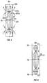
- Fig. 5 shows an injection electrode "A” and a return electrode “B”; these correspond to current electrodes 203a and 203b in the mud resistivity sensor of Fig. 4.
- the current lines from the injection electrode "A” flow towards the return electrode “B” and are free to depart from the axis of the sensor.
- R t is different from R m this flow produces an error.
- Electrode “A” is at a higher potential and electrode “B” is at a lower potential with respect to the background.
- a line V 0 denoted by 255 of zero potential relative to a background exists at a distance half way from A to B.
- the potential decreases gradually towards zero away from electrode “A” and increases gradually towards zero away from electrode “B”. This potential profile is important and will be contrasted with the case when the guard electrodes are present.
- electrodes "C1" and “C2” simulate the guard electrodes 201a and 201b of Fig. 4. If the electrodes “C1” and “C2” where not connected together, C1 would assume a positive potential and “C2" a negative potential and the general behavior of the sensor would not change significantly relative to the configuration of Fig. 5. If, however, "C1" and “C2" are connected together (at the same potential) due to symmetry they will assume a potential very close to zero (background potential). This drastically changes the current line configuration as can be seen schematically in Fig. 6. In this case there are three lines of zero potential indicated in the figure with Vo. The current lines 277 are mainly confined in this case to the borehole and the undesirable influence of R t on the R m measurement is drastically reduced.
- Fig. 7 results of modeling simulations with the configuration shown in Fig. 4 are illustrated.
- the abscissa is the ratio of the formation resistivity to the mud resistivity while the ordinate is the percentage error resulting from use of eq. (1) for obtaining the mud resistance.
- the curve 301 corresponds to values for d 1 and d 2 of 0.125" (- 3.2mm) and 1.125" (-28.6mm) respectively.
- the curve 303 is for values of 0.25" (-6.4mm) and 0.875"(-22.2mm), the curve 305 for 0.375" (-9.5mm) and 0.625" (-15.9mm), the curve 307 for 0.5"(-12.7mm) and 0.375" (- 9.5mm) while the curve 309 is for values for d 1 and d 2 of 0.625" (-15.9mm) and .125" (-3.2mm) respectively.
- the total length of the recessed interval was kept at 1.875" (-47.6mm) and the diameter of the measuring electrodes to 2"(-50.8mm).
- the present invention has been described with reference to a wireline implementation. It may also be used with little or no modification on measurement while drilling (MWD) implementations wherein the apparatus described is conveyed downhole on a drilling tubular.
- MWD measurement while drilling
Landscapes
- Physics & Mathematics (AREA)
- Engineering & Computer Science (AREA)
- Remote Sensing (AREA)
- Life Sciences & Earth Sciences (AREA)
- Electromagnetism (AREA)
- Environmental & Geological Engineering (AREA)
- Geology (AREA)
- General Life Sciences & Earth Sciences (AREA)
- General Physics & Mathematics (AREA)
- Geophysics (AREA)
- Geophysics And Detection Of Objects (AREA)
- Investigating Or Analyzing Materials By The Use Of Electric Means (AREA)
Claims (13)
- In einem Bohrloch geführte Vorrichtung zum Bestimmen einer Widerstandsgröße eines Fluids in dem Bohrloch, wobei die Vorrichtung umfasst:(a) ein Gehäuse (10) mit einem Paar von voneinander beabstandeten, defokussierenden Führungselektroden (201a, 201b); und(b) ein Paar von voneinander beabstandeten Stromelektroden (203a, 203b), die durch eine Vielzahl isolierenden Elementen (204a, 204b, 207a) voneinander und von den Führungselektroden (201a, 201b) getrennt sind, wobei die Stromelektroden (203a, 203b) in einem vertieften Bereich des Gehäuses (10) positioniert sind und die Führungselektroden (201a, 201b) außerhalb des vertieften Bereichs positioniert sind.
- Vorrichtung nach Anspruch 1, ferner umfassend ein Paar von Messelektroden (206a, 206b), die zwischen dem Paar von Stromelektroden (203a, 203b) angeordnet sind um einen Potentialabfall durch den Strom in dem Fluid zu messen.
- Vorrichtung nach Anspruch 2, wobei das Paar von Stromelektroden (203a, 203b) und das Paar von Messelektroden (206a, 206b) das Gleiche sind.
- Vorrichtung nach Anspruch 2, ferner umfassend einen Prozessor zum Bestimmen des Widerstandswerts des Fluids des Bohrlochs aus dem elektrischen Strom zwischen den Stromelektroden (203a, 203b) und einer Potenzialdifferenz zwischen dem Paar von Messelektroden (206a, 206b).
- Vorrichtung nach Anspruch 1, wobei ein Abstand zwischen dem Paar von Stromelektroden (203a, 203b) zwischen ungefähr 3,2mm und ungefähr 28,6mm beträgt.
- Vorrichtung nach Anspruch 1, wobei ein Abstand zwischen jeder aus dem Paar von Stromelektroden (203a, 203b) und einer entsprechenden Nächstliegenden der Führungselektroden (201a, 201b) zwischen ungefähr 3,2mm und ungefähr 15,0mm beträgt.
- Vorrichtung nach Anspruch 1, wobei die Vorrichtung dazu ausgelegt ist in ein Bohrloch entweder(i) einer Drahtleitung oder(ii) einer Bohrröhre geführt zu werden.
- Vorrichtung nach Anspruch 1, wobei das Paar von Führungselektroden (201a, 201b) auf ungefähr dem gleichen Potenzial liegt.
- Vorrichtung nach Anspruch 1, wobei das Paar von Führungselektroden (201a, 201b) einen elektrischen Strom zwischen den Stromelektroden abgrenzen, so dass er im Wesentlichen parallel zu einer Achse des Bohrlochs fließt.
- Verfahren zum Bestimmen eines Widerstandswerts eines Fluids in einem Bohrloch, wobei das Verfahren umfasst:(a) das Verwenden einer ersten Stromelektrode (203a, 203b), die in einer Vertiefung in einem Bohrlochmessungswerkzeug in dem Bohrloch angeordnet ist, zum Einführen eines Messstroms in das Fluid und das Empfangen des Stroms an einer zweiten Stromelektrode (203a, 203b) an dem Bohrlochmessungswerkzeug;(b) das Verwenden eines Paars von Messelektroden (206a, 206b), die in der Vertiefung in dem Bohrlochmessungswerkzeug angeordnet sind zum Messen einer Spannungsdifferenz in dem Fluid,(c) das Verwenden einer ersten defokussierenden Führungselektrode (201a, 201b) an dem Bohrlochmessungswerkzeug nahe bei und beabstandet von der ersten Stromelektrode (203a, 203b) und einer zweiten defokussierenden Führungselektrode (201a, 201b) an dem Bohrlochmessungswerkzeug nahe bei und beabstandet von der zweiten Stromelektrode (203a, 203b) zum Abgrenzen des Messstroms so dass er im Wesentlichen parallel zu einer Achse des Bohrlochs fließt, wobei die erste und die zweite Führungselektrode (201a, 201b) außerhalb der Vertiefung positioniert sind; und(d) das Bestimmen des Widerstandswerts des Fluids aus dem Messstrom und einer Spannungsdifferenz zwischen den Messelektroden des Fluids.
- Verfahren nach Anspruch 10, ferner umfassend das Einführen des Bohrlochmessungswerkzeugs in das Bohrloch entweder einer(i) Drahtleitung oder einer(ii) Bohrröhre.
- Verfahren nach Anspruch 10, wobei das Abgrenzen des Messstroms ferner das Halten der ersten und der zweiten Führungselektrode (201a, 201b) auf dem im Wesentlichen gleichen Potenzial umfasst.
- Verfahren nach Anspruch 12, wobei das Halten der ersten und der zweiten Führungselektrode (201a, 201b) ferner das Bereitstellen einer elektrischen Verbindung zwischen diesen umfasst.
Applications Claiming Priority (3)
| Application Number | Priority Date | Filing Date | Title |
|---|---|---|---|
| US10/142,307 US6801039B2 (en) | 2002-05-09 | 2002-05-09 | Apparatus and method for measuring mud resistivity using a defocused electrode system |
| US142307 | 2002-05-09 | ||
| PCT/US2003/014345 WO2003096074A1 (en) | 2002-05-09 | 2003-05-07 | Appararus and method for measuring mud resistivity using a defocused electrode system |
Publications (3)
| Publication Number | Publication Date |
|---|---|
| EP1567890A1 EP1567890A1 (de) | 2005-08-31 |
| EP1567890B1 true EP1567890B1 (de) | 2007-04-04 |
| EP1567890B8 EP1567890B8 (de) | 2007-06-13 |
Family
ID=29399860
Family Applications (1)
| Application Number | Title | Priority Date | Filing Date |
|---|---|---|---|
| EP03750087A Expired - Lifetime EP1567890B8 (de) | 2002-05-09 | 2003-05-07 | Messgerät und methode zur messung des widerstandes des bohrlochschlamms unter verwendung eines defokusierenden elektrodensystems |
Country Status (4)
| Country | Link |
|---|---|
| US (1) | US6801039B2 (de) |
| EP (1) | EP1567890B8 (de) |
| AU (1) | AU2003243208A1 (de) |
| WO (1) | WO2003096074A1 (de) |
Cited By (1)
| Publication number | Priority date | Publication date | Assignee | Title |
|---|---|---|---|---|
| CN104500028A (zh) * | 2014-11-07 | 2015-04-08 | 贝兹维仪器(苏州)有限公司 | 一种长条测量探板 |
Families Citing this family (36)
| Publication number | Priority date | Publication date | Assignee | Title |
|---|---|---|---|---|
| US7046010B2 (en) * | 2003-12-22 | 2006-05-16 | Halliburton Energy Services, Inc. | Multi-mode microresistivity tool in boreholes drilled with conductive mud |
| US7109719B2 (en) * | 2004-05-11 | 2006-09-19 | Baker Hughes Incorporated | Method and apparatus for azimuthal resistivity measurements in a borehole |
| US7299131B2 (en) | 2004-12-17 | 2007-11-20 | Baker Hughes Incorporated | Induction resistivity imaging principles and devices in oil based mud |
| US7313479B2 (en) * | 2005-01-31 | 2007-12-25 | Baker Hughes Incorporated | Method for real-time well-site interpretation of array resistivity log data in vertical and deviated wells |
| US7183778B2 (en) * | 2005-07-19 | 2007-02-27 | Schlumberger Technology Corporation | Apparatus and method to measure fluid resistivity |
| US7095233B1 (en) * | 2005-07-20 | 2006-08-22 | Schlumberger Technology Corporation | System, apparatus, and method of conducting borehole resistivity measurements |
| US7425827B2 (en) | 2005-10-03 | 2008-09-16 | Baker Hughes Incorporated | Method and apparatus for formation evaluation and borehole size determination |
| US7612567B2 (en) * | 2005-12-29 | 2009-11-03 | Baker Hughes Incorporated | Two-axial pad formation resistivity imager |
| US7629791B2 (en) * | 2006-08-01 | 2009-12-08 | Baker Hughes Incorporated | Method and apparatus for making multi-component measurements in deviated wells |
| US7778778B2 (en) * | 2006-08-01 | 2010-08-17 | Baker Hughes Incorporated | Correction of multi-component measurements for tool eccentricity in deviated wells |
| US7567869B2 (en) * | 2007-04-27 | 2009-07-28 | Baker Hughes Incorporated | Induction tool for detail evaluation of near borehole zone |
| MX2010005058A (es) * | 2007-11-09 | 2010-07-05 | Mi Llc | Medidor automatizado de estabilidad electrica. |
| US7896073B2 (en) * | 2008-06-10 | 2011-03-01 | Baker Hughes Incorporated | Apparatus for formation resistivity imaging in wells with oil-based drilling fluids |
| US8046170B2 (en) | 2008-09-03 | 2011-10-25 | Baker Hughes Incorporated | Apparatus and method for estimating eccentricity effects in resistivity measurements |
| ATE545048T1 (de) * | 2008-10-31 | 2012-02-15 | Prad Res & Dev Ltd | Gerät zur abbildung einer bohrlochumgebung |
| EP2182393B1 (de) * | 2008-10-31 | 2014-12-31 | Services Pétroliers Schlumberger | Werkzeug zur Darstellung einer Bohrlochumgebung |
| EP2182394A1 (de) * | 2008-10-31 | 2010-05-05 | Services Pétroliers Schlumberger | Werkzeug zur Darstellung einer Untertageumgebung |
| US8776878B2 (en) * | 2008-10-31 | 2014-07-15 | Schlumberger Technology Corporation | Sensor for determining downhole parameters and methods for using same |
| US20100179762A1 (en) * | 2009-01-12 | 2010-07-15 | Baker Hughes Incorporated | Method of Correcting Imaging Data For Standoff and Borehole Rugosity |
| EP2315056A1 (de) * | 2009-10-26 | 2011-04-27 | Services Pétroliers Schlumberger | Vorrichtung und Verfahren zur Untersuchung von Bohrlöchern, die mit leitfähigen oder nichtleitfähigen Flüssigkeiten gefüllt sind |
| EP2385366A1 (de) | 2010-02-19 | 2011-11-09 | Services Pétroliers Schlumberger | Flüssigkeitssensor und Verfahren zu dessen Verwendung |
| EP2362210B1 (de) | 2010-02-19 | 2015-01-07 | Services Pétroliers Schlumberger | Flüssigkeitssensor und Verfahren zu dessen Verwendung |
| US9423524B2 (en) * | 2010-04-07 | 2016-08-23 | Baker Hughes Incorporated | Oil-based mud imager with a line source |
| US9322796B2 (en) | 2010-06-01 | 2016-04-26 | Halliburton Energy Services, Inc. | Fluid resistivity sensor |
| US8616282B2 (en) | 2010-06-28 | 2013-12-31 | Schlumberger Technology Corporation | System and method for determining downhole fluid parameters |
| US8754651B2 (en) | 2010-11-15 | 2014-06-17 | Schlumberger Technology Corporation | System and method for imaging properties of subterranean formations |
| EP2498105B1 (de) | 2010-12-20 | 2014-08-27 | Services Pétroliers Schlumberger | Vorrichtung und Verfahren zum Messen der elektrischen Eigenschaften einer unterirdischen Formation |
| EP2541284A1 (de) | 2011-05-11 | 2013-01-02 | Services Pétroliers Schlumberger | System und Verfahren zur Erzeugung von flüssigkeitskompensierten Bohrlochparametern |
| US8860415B2 (en) * | 2011-05-24 | 2014-10-14 | Sondex Wireline Limited | Method and apparatus for measuring borehole mud resistivity |
| EP2749910A1 (de) | 2012-12-28 | 2014-07-02 | Services Pétroliers Schlumberger | Systeme und Verfahren zur Widerstandsmessung in mehreren Drehwinkeln |
| US10928543B2 (en) * | 2014-07-31 | 2021-02-23 | Halliburton Energy Services, Inc. | Electrical log processing near casing point |
| WO2016153617A1 (en) * | 2015-03-20 | 2016-09-29 | Halliburton Energy Services, Inc. | Measurement and control apparatus, systems, and methods |
| US11021950B2 (en) | 2019-06-06 | 2021-06-01 | Probe Technology Services, Inc. | Production-logging sensor |
| CN114981688A (zh) | 2020-01-28 | 2022-08-30 | 斯伦贝谢技术有限公司 | 用于表征地下地层的系统和方法 |
| US11892421B2 (en) | 2021-12-06 | 2024-02-06 | Schlumberger Technology Corporation | System and method for cleaning electrical stability probe |
| CN114879270B (zh) * | 2022-05-18 | 2024-12-03 | 中国地震局地震预测研究所 | 一种双通道交流地电阻率观测系统和观测方法 |
Family Cites Families (9)
| Publication number | Priority date | Publication date | Assignee | Title |
|---|---|---|---|---|
| FR2445532A1 (fr) | 1978-12-27 | 1980-07-25 | Schlumberger Prospection | Procede et dispositif pour mesurer la resistivite des fluides dans un sondage |
| US4524325A (en) * | 1982-09-30 | 1985-06-18 | Halliburton Company | Dual guard type resistivity measuring apparatus |
| US4658215A (en) * | 1983-06-20 | 1987-04-14 | Shell Oil Company | Method for induced polarization logging |
| AU5859886A (en) * | 1985-06-24 | 1987-01-08 | Halliburton Company | Investigating the resistivity of materials in the vicinity of focussed-current resistivity measurement apparatus in a borehole |
| FR2684453B1 (fr) * | 1991-11-28 | 1994-03-11 | Schlumberger Services Petroliers | Procede et dispositif de diagraphie a electrodes annulaires et azimutales. |
| EP0665958B1 (de) | 1993-07-21 | 1999-01-13 | Western Atlas International, Inc. | Verfahren zur formationwiderstandsbestimmung unter verwendung von kombinierten messungen mit induktiven und galvanischen bohrlochmessgeräten |
| NO310894B1 (no) | 1994-10-27 | 2001-09-10 | Schlumberger Technology Bv | Måling av slam-resistivitet i et borehull omfattende en sonde med en bunnelektrode for å sende en ström til og frabunnelektroden i en retning tiln¶rmet parallell med sondenslengdeakse |
| FR2740170B1 (fr) | 1995-10-20 | 1998-01-02 | Schlumberger Services Petrol | Procedes et dispositifs de mesure de la resistivite de la boue dans un puits d'hydrocarbure |
| US5900733A (en) | 1996-02-07 | 1999-05-04 | Schlumberger Technology Corporation | Well logging method and apparatus for determining downhole Borehole fluid resistivity, borehole diameter, and borehole corrected formation resistivity |
-
2002
- 2002-05-09 US US10/142,307 patent/US6801039B2/en not_active Expired - Lifetime
-
2003
- 2003-05-07 WO PCT/US2003/014345 patent/WO2003096074A1/en not_active Ceased
- 2003-05-07 EP EP03750087A patent/EP1567890B8/de not_active Expired - Lifetime
- 2003-05-07 AU AU2003243208A patent/AU2003243208A1/en not_active Abandoned
Cited By (1)
| Publication number | Priority date | Publication date | Assignee | Title |
|---|---|---|---|---|
| CN104500028A (zh) * | 2014-11-07 | 2015-04-08 | 贝兹维仪器(苏州)有限公司 | 一种长条测量探板 |
Also Published As
| Publication number | Publication date |
|---|---|
| WO2003096074A1 (en) | 2003-11-20 |
| EP1567890B8 (de) | 2007-06-13 |
| EP1567890A1 (de) | 2005-08-31 |
| US6801039B2 (en) | 2004-10-05 |
| AU2003243208A1 (en) | 2003-11-11 |
| US20030210061A1 (en) | 2003-11-13 |
Similar Documents
| Publication | Publication Date | Title |
|---|---|---|
| EP1567890B1 (de) | Messgerät und methode zur messung des widerstandes des bohrlochschlamms unter verwendung eines defokusierenden elektrodensystems | |
| US11466565B2 (en) | Modular resistivity sensor for downhole measurement while drilling | |
| US9360580B2 (en) | Method and apparatus for directional well logging | |
| US6534986B2 (en) | Permanently emplaced electromagnetic system and method for measuring formation resistivity adjacent to and between wells | |
| US6353321B1 (en) | Uncompensated electromagnetic wave resistivity tool for bed boundary detection and invasion profiling | |
| US7034538B2 (en) | Method for measuring earth formation resistivity through an electrically conductive wellbore casing | |
| US6308136B1 (en) | Method of interpreting induction logs in horizontal wells | |
| US20060255811A1 (en) | A Multi-Mode Oil Base Mud Imager | |
| EP2515146A2 (de) | Verfahren und Vorrichtung zur Verwendung eines Mehrkomponenteninduktionswerkzeugs zur Geolenkung und Formationswiderstandsdateninterpretation in horizontalen Bohrlöchern | |
| US20100134113A1 (en) | Single-well through casing induction logging tool | |
| CN100363758C (zh) | 用于感应-球形聚焦侧向测井的测井仪器和方法 | |
| US20040098201A1 (en) | Multi-frequency focusing for MWD resistivity tools | |
| NO346751B1 (en) | Apparatus and method for deep transient resistivity measurement | |
| EP0478409B1 (de) | Prospektionsverfahren und Vorrichtung zur Messung des Widerstandes von Erdformationen | |
| EP1970733B1 (de) | Vorrichtung und Verfahren zur elektrischen Untersuchung eines Bohrlochs | |
| WO2018143945A1 (en) | Optimization of ranging measurements | |
| EP1483602B1 (de) | Verwendung eines mehrfachkomponenten-induktionsmessgerätes für geosteuerung und interpretation der formationswiderstandsdaten in horizontalen bohrlöchern | |
| EP1996964B1 (de) | Magnetkopf für leitfähigkeitsbildgebung zur verwendung in bohrlöchern | |
| US7554328B2 (en) | Method and apparatus for reducing borehole and eccentricity effects in multicomponent induction logging | |
| US9229125B2 (en) | TDEM forward focusing system for downhole use | |
| EP3833850B1 (de) | Mehrfachoberflächenanregungsverfahren zur bestimmung eines ortes von bohrarbeiten an bestehenden bohrlöchern | |
| US20110006775A1 (en) | Apparatus and Method for Reducing Effects of Eccentricity in Induction Tools | |
| EP3542029B1 (de) | Aktive isolierende verbindung | |
| US5268641A (en) | Logging method and apparatus for measuring the Grondingen effect-corrected resistivity of earth formations | |
| EP3513035B1 (de) | Verwendung von zwischenräumen hinter einer spulenantenne in elektromagnetischen induktionswerkzeugen |
Legal Events
| Date | Code | Title | Description |
|---|---|---|---|
| PUAI | Public reference made under article 153(3) epc to a published international application that has entered the european phase |
Free format text: ORIGINAL CODE: 0009012 |
|
| 17P | Request for examination filed |
Effective date: 20050329 |
|
| AK | Designated contracting states |
Kind code of ref document: A1 Designated state(s): FR GB IT |
|
| RBV | Designated contracting states (corrected) |
Designated state(s): FR GB IT |
|
| RBV | Designated contracting states (corrected) |
Designated state(s): FR GB |
|
| GRAP | Despatch of communication of intention to grant a patent |
Free format text: ORIGINAL CODE: EPIDOSNIGR1 |
|
| GRAS | Grant fee paid |
Free format text: ORIGINAL CODE: EPIDOSNIGR3 |
|
| GRAA | (expected) grant |
Free format text: ORIGINAL CODE: 0009210 |
|
| AK | Designated contracting states |
Kind code of ref document: B1 Designated state(s): FR GB |
|
| REG | Reference to a national code |
Ref country code: GB Ref legal event code: FG4D |
|
| RTI2 | Title (correction) |
Free format text: APPARATUS AND METHOD FOR MEASURING MUD RESISTIVITY USING A DEFOCUSED ELECTRODE SYSTEM |
|
| RAP2 | Party data changed (patent owner data changed or rights of a patent transferred) |
Owner name: BAKER HUGHES INCORPORATED |
|
| ET | Fr: translation filed | ||
| REG | Reference to a national code |
Ref country code: FR Ref legal event code: CA |
|
| PLBE | No opposition filed within time limit |
Free format text: ORIGINAL CODE: 0009261 |
|
| STAA | Information on the status of an ep patent application or granted ep patent |
Free format text: STATUS: NO OPPOSITION FILED WITHIN TIME LIMIT |
|
| 26N | No opposition filed |
Effective date: 20080107 |
|
| PGFP | Annual fee paid to national office [announced via postgrant information from national office to epo] |
Ref country code: GB Payment date: 20140507 Year of fee payment: 12 |
|
| GBPC | Gb: european patent ceased through non-payment of renewal fee |
Effective date: 20150507 |
|
| REG | Reference to a national code |
Ref country code: FR Ref legal event code: PLFP Year of fee payment: 14 |
|
| PG25 | Lapsed in a contracting state [announced via postgrant information from national office to epo] |
Ref country code: GB Free format text: LAPSE BECAUSE OF NON-PAYMENT OF DUE FEES Effective date: 20150507 |
|
| PGFP | Annual fee paid to national office [announced via postgrant information from national office to epo] |
Ref country code: FR Payment date: 20160412 Year of fee payment: 14 |
|
| REG | Reference to a national code |
Ref country code: FR Ref legal event code: ST Effective date: 20180131 |
|
| PG25 | Lapsed in a contracting state [announced via postgrant information from national office to epo] |
Ref country code: FR Free format text: LAPSE BECAUSE OF NON-PAYMENT OF DUE FEES Effective date: 20170531 |