EP1567831B1 - Potentiometer - Google Patents
Potentiometer Download PDFInfo
- Publication number
- EP1567831B1 EP1567831B1 EP03778511A EP03778511A EP1567831B1 EP 1567831 B1 EP1567831 B1 EP 1567831B1 EP 03778511 A EP03778511 A EP 03778511A EP 03778511 A EP03778511 A EP 03778511A EP 1567831 B1 EP1567831 B1 EP 1567831B1
- Authority
- EP
- European Patent Office
- Prior art keywords
- potentiometer
- resistor
- contactor
- contact
- fingers
- Prior art date
- Legal status (The legal status is an assumption and is not a legal conclusion. Google has not performed a legal analysis and makes no representation as to the accuracy of the status listed.)
- Expired - Lifetime
Links
- 239000004020 conductor Substances 0.000 claims abstract description 17
- 230000008878 coupling Effects 0.000 claims abstract description 7
- 238000010168 coupling process Methods 0.000 claims abstract description 7
- 238000005859 coupling reaction Methods 0.000 claims abstract description 7
- 238000003780 insertion Methods 0.000 claims description 7
- 230000037431 insertion Effects 0.000 claims description 7
- 239000000463 material Substances 0.000 claims description 6
- 229910001220 stainless steel Inorganic materials 0.000 claims description 5
- 239000010935 stainless steel Substances 0.000 claims description 5
- 230000009471 action Effects 0.000 claims description 4
- 238000005452 bending Methods 0.000 claims description 4
- 239000002991 molded plastic Substances 0.000 claims description 4
- 239000000853 adhesive Substances 0.000 description 7
- 230000001070 adhesive effect Effects 0.000 description 7
- 239000010970 precious metal Substances 0.000 description 7
- 239000011324 bead Substances 0.000 description 4
- 230000008901 benefit Effects 0.000 description 4
- 238000007373 indentation Methods 0.000 description 3
- 238000004519 manufacturing process Methods 0.000 description 3
- 239000002184 metal Substances 0.000 description 3
- 238000006073 displacement reaction Methods 0.000 description 2
- 238000000034 method Methods 0.000 description 2
- 239000004033 plastic Substances 0.000 description 2
- 229920003023 plastic Polymers 0.000 description 2
- 210000002105 tongue Anatomy 0.000 description 2
- 230000015572 biosynthetic process Effects 0.000 description 1
- 230000008859 change Effects 0.000 description 1
- 238000002788 crimping Methods 0.000 description 1
- 230000001419 dependent effect Effects 0.000 description 1
- 230000006866 deterioration Effects 0.000 description 1
- 210000003734 kidney Anatomy 0.000 description 1
- 238000005192 partition Methods 0.000 description 1
- 230000008569 process Effects 0.000 description 1
- 230000004044 response Effects 0.000 description 1
- 230000035945 sensitivity Effects 0.000 description 1
- 238000000926 separation method Methods 0.000 description 1
- 239000007787 solid Substances 0.000 description 1
Images

Classifications
-
- G—PHYSICS
- G01—MEASURING; TESTING
- G01D—MEASURING NOT SPECIALLY ADAPTED FOR A SPECIFIC VARIABLE; ARRANGEMENTS FOR MEASURING TWO OR MORE VARIABLES NOT COVERED IN A SINGLE OTHER SUBCLASS; TARIFF METERING APPARATUS; MEASURING OR TESTING NOT OTHERWISE PROVIDED FOR
- G01D5/00—Mechanical means for transferring the output of a sensing member; Means for converting the output of a sensing member to another variable where the form or nature of the sensing member does not constrain the means for converting; Transducers not specially adapted for a specific variable
- G01D5/12—Mechanical means for transferring the output of a sensing member; Means for converting the output of a sensing member to another variable where the form or nature of the sensing member does not constrain the means for converting; Transducers not specially adapted for a specific variable using electric or magnetic means
- G01D5/14—Mechanical means for transferring the output of a sensing member; Means for converting the output of a sensing member to another variable where the form or nature of the sensing member does not constrain the means for converting; Transducers not specially adapted for a specific variable using electric or magnetic means influencing the magnitude of a current or voltage
- G01D5/16—Mechanical means for transferring the output of a sensing member; Means for converting the output of a sensing member to another variable where the form or nature of the sensing member does not constrain the means for converting; Transducers not specially adapted for a specific variable using electric or magnetic means influencing the magnitude of a current or voltage by varying resistance
- G01D5/165—Mechanical means for transferring the output of a sensing member; Means for converting the output of a sensing member to another variable where the form or nature of the sensing member does not constrain the means for converting; Transducers not specially adapted for a specific variable using electric or magnetic means influencing the magnitude of a current or voltage by varying resistance by relative movement of a point of contact or actuation and a resistive track
-
- G—PHYSICS
- G01—MEASURING; TESTING
- G01D—MEASURING NOT SPECIALLY ADAPTED FOR A SPECIFIC VARIABLE; ARRANGEMENTS FOR MEASURING TWO OR MORE VARIABLES NOT COVERED IN A SINGLE OTHER SUBCLASS; TARIFF METERING APPARATUS; MEASURING OR TESTING NOT OTHERWISE PROVIDED FOR
- G01D11/00—Component parts of measuring arrangements not specially adapted for a specific variable
- G01D11/24—Housings ; Casings for instruments
- G01D11/245—Housings for sensors
Definitions
- Another aim of the present invention is to provide a rotary potentiometer in which the components can be quickly and conveniently assembled or replaced.
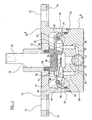
- the upper housing 10 a is further provided with a flange 70 extending radially beyond the lower housing 10 b .
- Arc-shaped slots 72 are formed in the flange 70 for receiving screws or bolts for mounting the potentiometer by screwing into mounting holes provided at a mounting location on the engine.
- the shaft 50, wiper carrier 54, spring contact 56 and wiper 60 are mounted in the upper housing 10 a which is then lowered onto the lower housing 10 b so that the precious metal bead 58 contacts the conductive boss 28, the precious metal wiper contact 62 contacts the resistor coil 42 and the upper housing 10 a engages the lower housing 10 b to form a seal against the O-ring 14. Finally, the upper housing 10 a is pushed over the O-ring seal 41 onto the lower housing 10 b and the two housings 10 a , 10 b are held together crimping of the metal ring 12. The complete assembly is a sealed unit with the electrical components sealed into the body 10 and protected from ingress of moisture or dirt.
Landscapes
- Physics & Mathematics (AREA)
- General Physics & Mathematics (AREA)
- Adjustable Resistors (AREA)
- Measurement Of Length, Angles, Or The Like Using Electric Or Magnetic Means (AREA)
- Surgical Instruments (AREA)
Claims (18)
- Potentiometer für das Bereitstellen eines Ausgangssignals, das eine Position eines Bauteils anzeigt, wobei das Potentiometer aufweist:ein Gehäuse (10);ein Element (50), das relativ zum Gehäuse (10) beweglich ist und einen Endabschnitt (80) für ein Verbinden mit dem Bauteil aufweist;einen Widerstand (42), der am Körper montiert ist;einen Schleifkontakt (60, 62), der mit dem Element (50) verbunden wird und einen verschiebbaren elektrischen Kontakt zum Widerstand (42) bildet;
gekennzeichnet durchKontaktgebermittel (30, 34) für das Bereitstellen von wählbaren Kontaktpositionen beim Widerstand des jeweiligen ersten (24) und zweiten elektrischen Leiters (26), um so einen ausgewählten Arbeitsabschnitt des Widerstandes (42) zu liefern. - Potentiometer nach Anspruch 1, bei dem
das Potentiometer ein Drehpotentiometer für das Bereitstellen eines Ausgangssignals ist, das eine Winkelposition des Bauteils anzeigt;
das Element (50) eine Welle mit einer Achse ist, wobei die Welle um die Achse relativ zum Gehäuse (10) drehbar ist;
der Widerstand (42) am Gehäuse (10) in einem Bogen um die Achse montiert ist; und
das Kontaktgebermittel (30, 34) für das Bereitstellen von wählbaren Kontaktpositionen beim Widerstand funktionsfähig ist, um so einen ausgewählten Arbeitswinkel des Potentiometers zu liefern. - Potentiometer nach Anspruch 1 oder Anspruch 2, bei dem der Widerstand (42) eine Widerstandsspule aufweist.
- Potentiometer nach einem der vorhergehenden Ansprüche, bei dem eine jede Kontaktposition durch die Auswahl eines leitenden Kontaktgebers (102, 104) aus einer Vielzahl von leitenden Kontaktgebern wählbar ist, so dass nur der ausgewählte Kontaktgeber den Widerstand (42) kontaktiert.
- Potentiometer nach Anspruch 4, bei dem die leitenden Kontaktgeber Kontaktgeberfinger (102, 104) aufweisen, wobei die Kontaktpositionen durch die Auswahl eines Fingers und Positionieren des ausgewählten Fingers in Kontakt mit dem Widerstand (42) wählbar sind.
- Potentiometer nach Anspruch 5, bei dem die Kontaktgeberfinger (102, 104) Finger einer Kontaktgeberplatte (30, 34) sind, wobei die ausgewählten Kontaktgeberfinger durch Biegen des Fingers relativ zur Platte positioniert werden, um so den Widerstand (42) zu kontaktieren.
- Potentiometer nach Anspruch 5, bei dem die Kontaktgeberfinger (102, 104) Finger einer Kontaktgeberplatte (30, 34) sind, wobei die ausgewählten Kontaktgeberfinger durch Biegen der nicht ausgewählten Finger relativ zur Platte positioniert werden, so dass nur der ausgewählte Finger den Widerstand (42) kontaktiert.
- Potentiometer nach Anspruch 6 oder Anspruch 7, bei dem die Kontaktgeberfinger (102, 104) um die Kontaktgeberplatte angeordnet sind, um einen Bereich von wählbaren Arbeitswinkeln zu liefern.
- Potentiometer nach einem der vorhergehenden Ansprüche, bei dem das Potentiometer mit zwei Kontaktgeberplatten (30, 34) versehen ist, eine für eine Verbindung eines jeden von erstem und zweitem elektrischen Leiter (24, 26) mit dem Widerstand (42).
- Potentiometer nach Anspruch 8 oder Anspruch 9, bei dem die oder jede Kontaktgeberplatte (30, 34) am Gehäuse (10) durch Presspassung über einem elastischen Vorsprung (46) montiert werden kann, der am Gehäuse (10) gebildet wird.
- Potentiometer nach Anspruch 3, bei dem die Widerstandsspule (42) am Gehäuse (10) mittels eines Montageringes (44) montiert wird, der die Spule zwischen dem Montagering und dem Gehäuse (10) festklemmt.
- Potentiometer nach Anspruch 11, bei dem der Montagering (44) am Gehäuse durch Presspassung über einem elastischen Vorsprung (48) montiert werden kann, der am Gehäuse (10) gebildet wird.
- Potentiometer nach Anspruch 2, bei dem die Welle (50) einen Endabschnitt (80) für ein Einsetzen in eine Öffnung des Bauteils aufweist, und
bei dem der Endabschnitt (80) eine Vielzahl von Segmenten (84, 86) aufweist, wobei die Segmente von der Achse weggespreizt werden, um so eine elastische Greifwirkung zu bewirken, wenn sie in die Öffnung eingesetzt werden. - Potentiometer nach Anspruch 13, bei dem der Endabschnitt (80) ein integrierter Teil der Welle (50) ist.
- Potentiometer nach Anspruch 13 oder Anspruch 14, bei dem die Segmente (84, 86) mit einer abgeschrägten Endfläche (88) versehen sind, um das Einsetzen in die Öffnung durch Zusammendrücken der Segmente in Richtung der Achse zu erleichtern, wenn die abgeschrägte Fläche gegen die Ränder der Öffnung gedrückt wird.
- Potentiometer nach Anspruch 2, bei dem das Gehäuse (10) einen axial zentrierten kreisförmigen Flansch (70) für das Montieren des Potentiometers mittels Schraubbefestigungsmittel aufweist, wobei der Flansch bogenförmige Schlitze (72) für das Aufnehmen des Befestigungsmittels aufweist, um so eine Einstellung der Winkelposition des Potentiometers zu gestatten,
und bei dem Montageeinsätze (74) bereitgestellt werden, die jeden bogenförmigen Schlitz (72) umgeben, wobei die Einsätze eine Fläche für das Anstoßen eines Kopfes eines Befestigungselementes aufweisen und aus einem Material sind, das einer dauerhaften Verformung widersteht, wenn das Befestigungselement angezogen wird. - Potentiometer nach Anspruch 16, bei dem die Montageeinsätze (74) aus einem nichtrostenden Stahl oder einem anderen haltbaren Material sind.
- Potentiometer nach Anspruch 2, bei dem das Gehäuse (10) ein geformtes Kunststoffgehäuse ist und elektrische Anschlüsse (18, 20, 22) für das Liefern einer Versorgungsspannung zum Potentiometer und für das Liefern des Ausgangssignals aufweist, wobei die elektrischen Anschlüsse mittels eines mehradrigen Kabels (16) bereitgestellt werden, das dauerhaft in das geformte Kunststoffgehäuse geformt ist
Applications Claiming Priority (3)
| Application Number | Priority Date | Filing Date | Title |
|---|---|---|---|
| GBGB0228392.7A GB0228392D0 (en) | 2002-12-05 | 2002-12-05 | Transducer |
| GB0228392 | 2002-12-05 | ||
| PCT/GB2003/005125 WO2004051194A1 (en) | 2002-12-05 | 2003-11-25 | Transducer |
Publications (2)
| Publication Number | Publication Date |
|---|---|
| EP1567831A1 EP1567831A1 (de) | 2005-08-31 |
| EP1567831B1 true EP1567831B1 (de) | 2008-07-23 |
Family
ID=9949131
Family Applications (1)
| Application Number | Title | Priority Date | Filing Date |
|---|---|---|---|
| EP03778511A Expired - Lifetime EP1567831B1 (de) | 2002-12-05 | 2003-11-25 | Potentiometer |
Country Status (7)
| Country | Link |
|---|---|
| US (1) | US7358747B2 (de) |
| EP (1) | EP1567831B1 (de) |
| AT (1) | ATE402397T1 (de) |
| AU (1) | AU2003285514A1 (de) |
| DE (1) | DE60322420D1 (de) |
| GB (1) | GB0228392D0 (de) |
| WO (1) | WO2004051194A1 (de) |
Families Citing this family (1)
| Publication number | Priority date | Publication date | Assignee | Title |
|---|---|---|---|---|
| GB0510440D0 (en) | 2005-05-21 | 2005-06-29 | Rolls Royce Plc | An instrumentation rake |
Family Cites Families (6)
| Publication number | Priority date | Publication date | Assignee | Title |
|---|---|---|---|---|
| US2442630A (en) | 1945-09-24 | 1948-06-01 | Liquidometer Corp | Resistance transmitter |
| DE3910360A1 (de) | 1989-03-31 | 1990-10-04 | Vdo Schindling | Lenkwinkelsensor |
| JP2796372B2 (ja) | 1989-09-20 | 1998-09-10 | 株式会社日立製作所 | スロツトルセンサ |
| US5657544A (en) * | 1995-09-26 | 1997-08-19 | Ntn Corporation | Device for detecting the angle of rotation |
| JPH11271013A (ja) | 1998-03-20 | 1999-10-05 | Unisia Jecs Corp | 回動角検出装置 |
| US6331768B1 (en) * | 2000-06-13 | 2001-12-18 | Xicor, Inc. | High-resolution, high-precision solid-state potentiometer |
-
2002
- 2002-12-05 GB GBGB0228392.7A patent/GB0228392D0/en not_active Ceased
-
2003
- 2003-11-25 AU AU2003285514A patent/AU2003285514A1/en not_active Abandoned
- 2003-11-25 AT AT03778511T patent/ATE402397T1/de not_active IP Right Cessation
- 2003-11-25 WO PCT/GB2003/005125 patent/WO2004051194A1/en not_active Ceased
- 2003-11-25 US US10/537,561 patent/US7358747B2/en not_active Expired - Fee Related
- 2003-11-25 EP EP03778511A patent/EP1567831B1/de not_active Expired - Lifetime
- 2003-11-25 DE DE60322420T patent/DE60322420D1/de not_active Expired - Fee Related
Also Published As
| Publication number | Publication date |
|---|---|
| AU2003285514A1 (en) | 2004-06-23 |
| WO2004051194A1 (en) | 2004-06-17 |
| US7358747B2 (en) | 2008-04-15 |
| ATE402397T1 (de) | 2008-08-15 |
| EP1567831A1 (de) | 2005-08-31 |
| DE60322420D1 (en) | 2008-09-04 |
| US20060132150A1 (en) | 2006-06-22 |
| GB0228392D0 (en) | 2003-01-08 |
Similar Documents
| Publication | Publication Date | Title |
|---|---|---|
| US5021760A (en) | Solenoid switch contact and mounting assembly | |
| US5486758A (en) | Integral variable reluctance speed sensor | |
| CN104903987B (zh) | 旋转操作型电子部件 | |
| US6731194B1 (en) | Rotary sensor in which sensor rotation shaft is prevented from becoming eccentric | |
| US7367793B2 (en) | Mold with movable core insert | |
| US7358747B2 (en) | Rotary potentiometer with selectable operating section | |
| US4718278A (en) | Pressure transducer with improved calibration | |
| US3996549A (en) | Electrical control and mechanical coupling therefor | |
| EP1420228B1 (de) | Drehgeber | |
| US6441626B1 (en) | Rotary position sensor | |
| EP0319264B1 (de) | Zungenschalter für Drehwellenstellung | |
| JPH0562410B2 (de) | ||
| US4947150A (en) | Pressure sender | |
| JPS5936904A (ja) | 作動レバ−をポテンシヨメ−タに組付ける方法 | |
| US5939685A (en) | Stopping device with a switch | |
| EP0940822B1 (de) | Veränderbarer Widerstand | |
| US6693249B2 (en) | Inhibitor switch | |
| KR0181750B1 (ko) | 클러치 기구를 구비한 가변 저항기 | |
| US3378804A (en) | Resistive devices | |
| JP3687103B2 (ja) | 圧力スイッチ | |
| WO2017056581A1 (ja) | コネクタ | |
| JPH0991814A (ja) | 磁気ディスクドライバのチャッキング機構 | |
| JP6469278B1 (ja) | 巻線型ポテンショメータ | |
| JPS58223220A (ja) | 電気的な回転スイツチ | |
| CN216055209U (zh) | 用于连接电性导体的连接端子 |
Legal Events
| Date | Code | Title | Description |
|---|---|---|---|
| PUAI | Public reference made under article 153(3) epc to a published international application that has entered the european phase |
Free format text: ORIGINAL CODE: 0009012 |
|
| 17P | Request for examination filed |
Effective date: 20050629 |
|
| AK | Designated contracting states |
Kind code of ref document: A1 Designated state(s): AT BE BG CH CY CZ DE DK EE ES FI FR GB GR HU IE IT LI LU MC NL PT RO SE SI SK TR |
|
| AX | Request for extension of the european patent |
Extension state: AL LT LV MK |
|
| DAX | Request for extension of the european patent (deleted) | ||
| 17Q | First examination report despatched |
Effective date: 20070323 |
|
| GRAP | Despatch of communication of intention to grant a patent |
Free format text: ORIGINAL CODE: EPIDOSNIGR1 |
|
| RTI1 | Title (correction) |
Free format text: POTENTIOMETER |
|
| GRAS | Grant fee paid |
Free format text: ORIGINAL CODE: EPIDOSNIGR3 |
|
| GRAA | (expected) grant |
Free format text: ORIGINAL CODE: 0009210 |
|
| AK | Designated contracting states |
Kind code of ref document: B1 Designated state(s): AT BE BG CH CY CZ DE DK EE ES FI FR GB GR HU IE IT LI LU MC NL PT RO SE SI SK TR |
|
| REG | Reference to a national code |
Ref country code: GB Ref legal event code: FG4D |
|
| REG | Reference to a national code |
Ref country code: CH Ref legal event code: EP |
|
| REG | Reference to a national code |
Ref country code: IE Ref legal event code: FG4D |
|
| REF | Corresponds to: |
Ref document number: 60322420 Country of ref document: DE Date of ref document: 20080904 Kind code of ref document: P |
|
| NLV1 | Nl: lapsed or annulled due to failure to fulfill the requirements of art. 29p and 29m of the patents act | ||
| PG25 | Lapsed in a contracting state [announced via postgrant information from national office to epo] |
Ref country code: ES Free format text: LAPSE BECAUSE OF FAILURE TO SUBMIT A TRANSLATION OF THE DESCRIPTION OR TO PAY THE FEE WITHIN THE PRESCRIBED TIME-LIMIT Effective date: 20081103 Ref country code: PT Free format text: LAPSE BECAUSE OF FAILURE TO SUBMIT A TRANSLATION OF THE DESCRIPTION OR TO PAY THE FEE WITHIN THE PRESCRIBED TIME-LIMIT Effective date: 20081223 Ref country code: NL Free format text: LAPSE BECAUSE OF FAILURE TO SUBMIT A TRANSLATION OF THE DESCRIPTION OR TO PAY THE FEE WITHIN THE PRESCRIBED TIME-LIMIT Effective date: 20080723 |
|
| PGFP | Annual fee paid to national office [announced via postgrant information from national office to epo] |
Ref country code: CH Payment date: 20081130 Year of fee payment: 6 Ref country code: DE Payment date: 20081120 Year of fee payment: 6 Ref country code: LU Payment date: 20081203 Year of fee payment: 6 |
|
| PG25 | Lapsed in a contracting state [announced via postgrant information from national office to epo] |
Ref country code: SI Free format text: LAPSE BECAUSE OF FAILURE TO SUBMIT A TRANSLATION OF THE DESCRIPTION OR TO PAY THE FEE WITHIN THE PRESCRIBED TIME-LIMIT Effective date: 20080723 Ref country code: AT Free format text: LAPSE BECAUSE OF FAILURE TO SUBMIT A TRANSLATION OF THE DESCRIPTION OR TO PAY THE FEE WITHIN THE PRESCRIBED TIME-LIMIT Effective date: 20080723 Ref country code: FI Free format text: LAPSE BECAUSE OF FAILURE TO SUBMIT A TRANSLATION OF THE DESCRIPTION OR TO PAY THE FEE WITHIN THE PRESCRIBED TIME-LIMIT Effective date: 20080723 Ref country code: BG Free format text: LAPSE BECAUSE OF FAILURE TO SUBMIT A TRANSLATION OF THE DESCRIPTION OR TO PAY THE FEE WITHIN THE PRESCRIBED TIME-LIMIT Effective date: 20081023 |
|
| PG25 | Lapsed in a contracting state [announced via postgrant information from national office to epo] |
Ref country code: BE Free format text: LAPSE BECAUSE OF FAILURE TO SUBMIT A TRANSLATION OF THE DESCRIPTION OR TO PAY THE FEE WITHIN THE PRESCRIBED TIME-LIMIT Effective date: 20080723 |
|
| PGFP | Annual fee paid to national office [announced via postgrant information from national office to epo] |
Ref country code: BE Payment date: 20081017 Year of fee payment: 6 |
|
| PG25 | Lapsed in a contracting state [announced via postgrant information from national office to epo] |
Ref country code: EE Free format text: LAPSE BECAUSE OF FAILURE TO SUBMIT A TRANSLATION OF THE DESCRIPTION OR TO PAY THE FEE WITHIN THE PRESCRIBED TIME-LIMIT Effective date: 20080723 Ref country code: DK Free format text: LAPSE BECAUSE OF FAILURE TO SUBMIT A TRANSLATION OF THE DESCRIPTION OR TO PAY THE FEE WITHIN THE PRESCRIBED TIME-LIMIT Effective date: 20080723 |
|
| PGFP | Annual fee paid to national office [announced via postgrant information from national office to epo] |
Ref country code: FR Payment date: 20081112 Year of fee payment: 6 |
|
| PG25 | Lapsed in a contracting state [announced via postgrant information from national office to epo] |
Ref country code: SK Free format text: LAPSE BECAUSE OF FAILURE TO SUBMIT A TRANSLATION OF THE DESCRIPTION OR TO PAY THE FEE WITHIN THE PRESCRIBED TIME-LIMIT Effective date: 20080723 Ref country code: RO Free format text: LAPSE BECAUSE OF FAILURE TO SUBMIT A TRANSLATION OF THE DESCRIPTION OR TO PAY THE FEE WITHIN THE PRESCRIBED TIME-LIMIT Effective date: 20080723 Ref country code: CZ Free format text: LAPSE BECAUSE OF FAILURE TO SUBMIT A TRANSLATION OF THE DESCRIPTION OR TO PAY THE FEE WITHIN THE PRESCRIBED TIME-LIMIT Effective date: 20080723 |
|
| PLBE | No opposition filed within time limit |
Free format text: ORIGINAL CODE: 0009261 |
|
| STAA | Information on the status of an ep patent application or granted ep patent |
Free format text: STATUS: NO OPPOSITION FILED WITHIN TIME LIMIT |
|
| PG25 | Lapsed in a contracting state [announced via postgrant information from national office to epo] |
Ref country code: MC Free format text: LAPSE BECAUSE OF NON-PAYMENT OF DUE FEES Effective date: 20081130 |
|
| 26N | No opposition filed |
Effective date: 20090424 |
|
| REG | Reference to a national code |
Ref country code: IE Ref legal event code: MM4A |
|
| PG25 | Lapsed in a contracting state [announced via postgrant information from national office to epo] |
Ref country code: IT Free format text: LAPSE BECAUSE OF FAILURE TO SUBMIT A TRANSLATION OF THE DESCRIPTION OR TO PAY THE FEE WITHIN THE PRESCRIBED TIME-LIMIT Effective date: 20080723 |
|
| PG25 | Lapsed in a contracting state [announced via postgrant information from national office to epo] |
Ref country code: IE Free format text: LAPSE BECAUSE OF NON-PAYMENT OF DUE FEES Effective date: 20081125 |
|
| PG25 | Lapsed in a contracting state [announced via postgrant information from national office to epo] |
Ref country code: SE Free format text: LAPSE BECAUSE OF FAILURE TO SUBMIT A TRANSLATION OF THE DESCRIPTION OR TO PAY THE FEE WITHIN THE PRESCRIBED TIME-LIMIT Effective date: 20081023 |
|
| REG | Reference to a national code |
Ref country code: CH Ref legal event code: PL |
|
| PG25 | Lapsed in a contracting state [announced via postgrant information from national office to epo] |
Ref country code: HU Free format text: LAPSE BECAUSE OF FAILURE TO SUBMIT A TRANSLATION OF THE DESCRIPTION OR TO PAY THE FEE WITHIN THE PRESCRIBED TIME-LIMIT Effective date: 20090124 Ref country code: CY Free format text: LAPSE BECAUSE OF FAILURE TO SUBMIT A TRANSLATION OF THE DESCRIPTION OR TO PAY THE FEE WITHIN THE PRESCRIBED TIME-LIMIT Effective date: 20080723 |
|
| REG | Reference to a national code |
Ref country code: FR Ref legal event code: ST Effective date: 20100730 |
|
| PG25 | Lapsed in a contracting state [announced via postgrant information from national office to epo] |
Ref country code: TR Free format text: LAPSE BECAUSE OF FAILURE TO SUBMIT A TRANSLATION OF THE DESCRIPTION OR TO PAY THE FEE WITHIN THE PRESCRIBED TIME-LIMIT Effective date: 20080723 |
|
| PG25 | Lapsed in a contracting state [announced via postgrant information from national office to epo] |
Ref country code: FR Free format text: LAPSE BECAUSE OF NON-PAYMENT OF DUE FEES Effective date: 20091130 Ref country code: LI Free format text: LAPSE BECAUSE OF NON-PAYMENT OF DUE FEES Effective date: 20091130 Ref country code: GR Free format text: LAPSE BECAUSE OF FAILURE TO SUBMIT A TRANSLATION OF THE DESCRIPTION OR TO PAY THE FEE WITHIN THE PRESCRIBED TIME-LIMIT Effective date: 20081024 Ref country code: CH Free format text: LAPSE BECAUSE OF NON-PAYMENT OF DUE FEES Effective date: 20091130 |
|
| PG25 | Lapsed in a contracting state [announced via postgrant information from national office to epo] |
Ref country code: DE Free format text: LAPSE BECAUSE OF NON-PAYMENT OF DUE FEES Effective date: 20100601 |
|
| PG25 | Lapsed in a contracting state [announced via postgrant information from national office to epo] |
Ref country code: LU Free format text: LAPSE BECAUSE OF NON-PAYMENT OF DUE FEES Effective date: 20091125 |
|
| PGFP | Annual fee paid to national office [announced via postgrant information from national office to epo] |
Ref country code: GB Payment date: 20110526 Year of fee payment: 8 |
|
| GBPC | Gb: european patent ceased through non-payment of renewal fee |
Effective date: 20111125 |
|
| PG25 | Lapsed in a contracting state [announced via postgrant information from national office to epo] |
Ref country code: GB Free format text: LAPSE BECAUSE OF NON-PAYMENT OF DUE FEES Effective date: 20111125 |