EP1567371B1 - Twist-beam axle for the rear suspension of a motor vehicle and method for its production - Google Patents
Twist-beam axle for the rear suspension of a motor vehicle and method for its production Download PDFInfo
- Publication number
- EP1567371B1 EP1567371B1 EP03772307A EP03772307A EP1567371B1 EP 1567371 B1 EP1567371 B1 EP 1567371B1 EP 03772307 A EP03772307 A EP 03772307A EP 03772307 A EP03772307 A EP 03772307A EP 1567371 B1 EP1567371 B1 EP 1567371B1
- Authority
- EP
- European Patent Office
- Prior art keywords
- shells
- cross
- transversely
- inner half
- side end
- Prior art date
- Legal status (The legal status is an assumption and is not a legal conclusion. Google has not performed a legal analysis and makes no representation as to the accuracy of the status listed.)
- Expired - Lifetime
Links
- 239000000725 suspension Substances 0.000 title claims description 11
- 238000004519 manufacturing process Methods 0.000 title claims description 8
- 238000000034 method Methods 0.000 title claims description 7
- 238000003466 welding Methods 0.000 claims description 15
- 238000005304 joining Methods 0.000 claims description 7
- 239000011324 bead Substances 0.000 claims description 2
- 238000010276 construction Methods 0.000 description 1
- 239000002184 metal Substances 0.000 description 1
Images



Classifications
-
- B—PERFORMING OPERATIONS; TRANSPORTING
- B60—VEHICLES IN GENERAL
- B60B—VEHICLE WHEELS; CASTORS; AXLES FOR WHEELS OR CASTORS; INCREASING WHEEL ADHESION
- B60B35/00—Axle units; Parts thereof ; Arrangements for lubrication of axles
- B60B35/004—Mounting arrangements for axles
- B60B35/006—Mounting arrangements for axles with mounting plates or consoles fitted to axles
- B60B35/007—Mounting arrangements for axles with mounting plates or consoles fitted to axles for mounting suspension elements to axles
-
- B—PERFORMING OPERATIONS; TRANSPORTING
- B60—VEHICLES IN GENERAL
- B60B—VEHICLE WHEELS; CASTORS; AXLES FOR WHEELS OR CASTORS; INCREASING WHEEL ADHESION
- B60B35/00—Axle units; Parts thereof ; Arrangements for lubrication of axles
- B60B35/02—Dead axles, i.e. not transmitting torque
- B60B35/04—Dead axles, i.e. not transmitting torque straight
-
- B—PERFORMING OPERATIONS; TRANSPORTING
- B60—VEHICLES IN GENERAL
- B60G—VEHICLE SUSPENSION ARRANGEMENTS
- B60G21/00—Interconnection systems for two or more resiliently-suspended wheels, e.g. for stabilising a vehicle body with respect to acceleration, deceleration or centrifugal forces
- B60G21/02—Interconnection systems for two or more resiliently-suspended wheels, e.g. for stabilising a vehicle body with respect to acceleration, deceleration or centrifugal forces permanently interconnected
- B60G21/04—Interconnection systems for two or more resiliently-suspended wheels, e.g. for stabilising a vehicle body with respect to acceleration, deceleration or centrifugal forces permanently interconnected mechanically
- B60G21/05—Interconnection systems for two or more resiliently-suspended wheels, e.g. for stabilising a vehicle body with respect to acceleration, deceleration or centrifugal forces permanently interconnected mechanically between wheels on the same axle but on different sides of the vehicle, i.e. the left and right wheel suspensions being interconnected
- B60G21/051—Trailing arm twist beam axles
-
- B—PERFORMING OPERATIONS; TRANSPORTING
- B60—VEHICLES IN GENERAL
- B60G—VEHICLE SUSPENSION ARRANGEMENTS
- B60G7/00—Pivoted suspension arms; Accessories thereof
- B60G7/001—Suspension arms, e.g. constructional features
-
- B—PERFORMING OPERATIONS; TRANSPORTING
- B60—VEHICLES IN GENERAL
- B60B—VEHICLE WHEELS; CASTORS; AXLES FOR WHEELS OR CASTORS; INCREASING WHEEL ADHESION
- B60B2310/00—Manufacturing methods
- B60B2310/30—Manufacturing methods joining
- B60B2310/302—Manufacturing methods joining by welding
-
- B—PERFORMING OPERATIONS; TRANSPORTING
- B60—VEHICLES IN GENERAL
- B60B—VEHICLE WHEELS; CASTORS; AXLES FOR WHEELS OR CASTORS; INCREASING WHEEL ADHESION
- B60B2360/00—Materials; Physical forms thereof
- B60B2360/10—Metallic materials
-
- B—PERFORMING OPERATIONS; TRANSPORTING
- B60—VEHICLES IN GENERAL
- B60B—VEHICLE WHEELS; CASTORS; AXLES FOR WHEELS OR CASTORS; INCREASING WHEEL ADHESION
- B60B2360/00—Materials; Physical forms thereof
- B60B2360/14—Physical forms of metallic parts
- B60B2360/141—Sheet-metals
-
- B—PERFORMING OPERATIONS; TRANSPORTING
- B60—VEHICLES IN GENERAL
- B60B—VEHICLE WHEELS; CASTORS; AXLES FOR WHEELS OR CASTORS; INCREASING WHEEL ADHESION
- B60B2360/00—Materials; Physical forms thereof
- B60B2360/14—Physical forms of metallic parts
- B60B2360/145—Profiles, i.e. being solid and having irregular cross-section
- B60B2360/1458—U or V-Profiles
-
- B—PERFORMING OPERATIONS; TRANSPORTING
- B60—VEHICLES IN GENERAL
- B60B—VEHICLE WHEELS; CASTORS; AXLES FOR WHEELS OR CASTORS; INCREASING WHEEL ADHESION
- B60B2900/00—Purpose of invention
- B60B2900/30—Increase in
- B60B2900/311—Rigidity or stiffness
-
- B—PERFORMING OPERATIONS; TRANSPORTING
- B60—VEHICLES IN GENERAL
- B60G—VEHICLE SUSPENSION ARRANGEMENTS
- B60G2202/00—Indexing codes relating to the type of spring, damper or actuator
- B60G2202/10—Type of spring
- B60G2202/13—Torsion spring
- B60G2202/136—Twist-beam type arrangement
- B60G2202/1362—Twist-beam type arrangement including a second torsional element, e.g. second beam, stabiliser bar or tube
-
- B—PERFORMING OPERATIONS; TRANSPORTING
- B60—VEHICLES IN GENERAL
- B60G—VEHICLE SUSPENSION ARRANGEMENTS
- B60G2204/00—Indexing codes related to suspensions per se or to auxiliary parts
- B60G2204/10—Mounting of suspension elements
- B60G2204/12—Mounting of springs or dampers
- B60G2204/122—Mounting of torsion springs
- B60G2204/1226—Mounting of torsion springs on the trailing arms of a twist beam type arrangement
-
- B—PERFORMING OPERATIONS; TRANSPORTING
- B60—VEHICLES IN GENERAL
- B60G—VEHICLE SUSPENSION ARRANGEMENTS
- B60G2204/00—Indexing codes related to suspensions per se or to auxiliary parts
- B60G2204/10—Mounting of suspension elements
- B60G2204/12—Mounting of springs or dampers
- B60G2204/124—Mounting of coil springs
- B60G2204/1244—Mounting of coil springs on a suspension arm
-
- B—PERFORMING OPERATIONS; TRANSPORTING
- B60—VEHICLES IN GENERAL
- B60G—VEHICLE SUSPENSION ARRANGEMENTS
- B60G2204/00—Indexing codes related to suspensions per se or to auxiliary parts
- B60G2204/10—Mounting of suspension elements
- B60G2204/12—Mounting of springs or dampers
- B60G2204/124—Mounting of coil springs
- B60G2204/1246—Mounting of coil springs on twist beam axles
-
- B—PERFORMING OPERATIONS; TRANSPORTING
- B60—VEHICLES IN GENERAL
- B60G—VEHICLE SUSPENSION ARRANGEMENTS
- B60G2206/00—Indexing codes related to the manufacturing of suspensions: constructional features, the materials used, procedures or tools
- B60G2206/01—Constructional features of suspension elements, e.g. arms, dampers, springs
- B60G2206/10—Constructional features of arms
-
- B—PERFORMING OPERATIONS; TRANSPORTING
- B60—VEHICLES IN GENERAL
- B60G—VEHICLE SUSPENSION ARRANGEMENTS
- B60G2206/00—Indexing codes related to the manufacturing of suspensions: constructional features, the materials used, procedures or tools
- B60G2206/01—Constructional features of suspension elements, e.g. arms, dampers, springs
- B60G2206/20—Constructional features of semi-rigid axles, e.g. twist beam type axles
-
- B—PERFORMING OPERATIONS; TRANSPORTING
- B60—VEHICLES IN GENERAL
- B60G—VEHICLE SUSPENSION ARRANGEMENTS
- B60G2206/00—Indexing codes related to the manufacturing of suspensions: constructional features, the materials used, procedures or tools
- B60G2206/01—Constructional features of suspension elements, e.g. arms, dampers, springs
- B60G2206/30—Constructional features of rigid axles
-
- B—PERFORMING OPERATIONS; TRANSPORTING
- B60—VEHICLES IN GENERAL
- B60G—VEHICLE SUSPENSION ARRANGEMENTS
- B60G2206/00—Indexing codes related to the manufacturing of suspensions: constructional features, the materials used, procedures or tools
- B60G2206/01—Constructional features of suspension elements, e.g. arms, dampers, springs
- B60G2206/50—Constructional features of wheel supports or knuckles, e.g. steering knuckles, spindle attachments
-
- B—PERFORMING OPERATIONS; TRANSPORTING
- B60—VEHICLES IN GENERAL
- B60G—VEHICLE SUSPENSION ARRANGEMENTS
- B60G2206/00—Indexing codes related to the manufacturing of suspensions: constructional features, the materials used, procedures or tools
- B60G2206/01—Constructional features of suspension elements, e.g. arms, dampers, springs
- B60G2206/70—Materials used in suspensions
- B60G2206/72—Steel
- B60G2206/722—Plates
-
- B—PERFORMING OPERATIONS; TRANSPORTING
- B60—VEHICLES IN GENERAL
- B60G—VEHICLE SUSPENSION ARRANGEMENTS
- B60G2206/00—Indexing codes related to the manufacturing of suspensions: constructional features, the materials used, procedures or tools
- B60G2206/01—Constructional features of suspension elements, e.g. arms, dampers, springs
- B60G2206/80—Manufacturing procedures
- B60G2206/81—Shaping
- B60G2206/8103—Shaping by folding or bending
-
- B—PERFORMING OPERATIONS; TRANSPORTING
- B60—VEHICLES IN GENERAL
- B60G—VEHICLE SUSPENSION ARRANGEMENTS
- B60G2206/00—Indexing codes related to the manufacturing of suspensions: constructional features, the materials used, procedures or tools
- B60G2206/01—Constructional features of suspension elements, e.g. arms, dampers, springs
- B60G2206/80—Manufacturing procedures
- B60G2206/82—Joining
- B60G2206/8201—Joining by welding
-
- Y—GENERAL TAGGING OF NEW TECHNOLOGICAL DEVELOPMENTS; GENERAL TAGGING OF CROSS-SECTIONAL TECHNOLOGIES SPANNING OVER SEVERAL SECTIONS OF THE IPC; TECHNICAL SUBJECTS COVERED BY FORMER USPC CROSS-REFERENCE ART COLLECTIONS [XRACs] AND DIGESTS
- Y10—TECHNICAL SUBJECTS COVERED BY FORMER USPC
- Y10T—TECHNICAL SUBJECTS COVERED BY FORMER US CLASSIFICATION
- Y10T29/00—Metal working
- Y10T29/49—Method of mechanical manufacture
- Y10T29/49616—Structural member making
- Y10T29/49622—Vehicular structural member making
Definitions
- the present invention relates to a twist-beam axle for the rear suspension of a motor vehicle, as well as a method for the production of such a twist-beam axle.
- the trailing arms of the twist-beam axle are formed as elongated integral bodies, for example of tubular shape, which are securely connected to the cross-member, for example by welding.
- a pair of trailing half-arms that is, a front half-arm and a rear half-arm, respectively, may be provided for instead of a single trailing arm, wherein usually the rear half-arm is formed as a single piece with the cross-member whereas the front one is fixed to the cross-member, for example by welding.
- each trailing arm comprises a pair of transversely inner half-shells, that is, a front half-shell and a rear half-shell, respectively, which are formed by prolongations of the respective end portion of the cross member, and a transversely outer half-shell securely connected to the pair of transversely inner half-shells so as to form therewith a structure having a closed cross-section.
- US-A-4 486 030 discloses a rear suspension for a motor vehicle, comprising a pair of trailing arms extending in a longitudinal direction of the vehicle and a torsion beam of substantially U-shaped cross section, which is welded to and extends transversely between the trailing arms so as to be positioned intermediate the forward end and the backward end of each trailing arm.
- US-A-6 047 978 discloses a twist-beam axle for the rear suspension of a motor vehicle, comprising a pair of trailing arms arranged to extend substantially longitudinally of the vehicle in a laterally symmetrical relationship thereto with each front end thereof being pivotably mounted to the vehicle body while each rear end thereof opposite to said front end rotatably supporting a corresponding one of the pair of rear wheels, and a torsion beam arranged to extend substantially laterally of the vehicle between the pair of trailing arms with opposite ends thereof being firmly connected thereto by welding.
- Each trailing arm is formed as a single piece of generally tubular construction.
- this object is fully achieved according to the invention by virtue of a twist-beam axle for the rear suspension of a motor vehicle having the characteristics defined in independent Claim 1. According to another aspect of the invention, this object is fully achieved by virtue of a method for the production of a twist-beam axle for the rear suspension of a motor vehicle as defined in independent Claim 9.
- each of the two trailing arms is comprised of a pair of first, transversely inner half-shells, that is, a front half-shell and a rear half-shell, respectively, securely connected to each other and to the respective end of the cross-member by welding, and of a second, transversely outer half-shell, securely connected to the first two half-shells by welding so as to form therewith a rigid body having a closed cross-section.
- a twist-beam axle for the rear suspension of a motor vehicle is generally indicated 10 and comprises a central cross-member 11 and a pair of trailing arms 12 fixed to respective side end portions 11a of the cross-member (in the figures only the left-hand end is shown).
- a bush 13 for articulation of the twist-beam axle 10 to the vehicle body is fixed to the front end of each trailing arm 12, whereas a mounting structure 14 for a wheel-carrier (not shown) and a sheet plate 15 intended to provide a lower support surface for a spring (also, not shown) are fixed to the rear portion of the arm 12, on the transversely outer side and the transversely inner side, respectively.
- the middle portion of the cross-member 11, indicated 11b has in its vertical plane of symmetry a cross-section of predetermined shape, in the illustrated example an omega-shape, adapted to provide the cross-member with the required elastic characteristics, in particular the compliance to torsion.
- the end portions 11a of the cross-member 11 form each a head wall 11c, downwardly inclined in the transverse direction, in which a hole 16 is provided for being passed through by a torsion bar 17 housed inside the middle portion 11b of the cross-member 11 and fixed at its ends to the trailing arms 12.
- the torsion bar 17 may be fixed to the head walls 11c of the side portions 11a of the cross-member, instead of being fixed to the trailing arms 12.
- the middle portion 11b of the cross-member may assume obviously any other suitable shape, either open (as in the illustrated example) or closed.
- each trailing arm 12 is comprised of three sheet metal parts 18, 19 and 20, formed as half-shells with open, essentially C-shaped cross-section, securely connected to each other, preferably by welding.
- These elements are a pair of transversely inner half-shells 18 and 19, that is, a front half-shell and a rear half-shell, respectively, intended to be fixed to the end portion 11a of the cross-member 11, and a transversely outer half-shell 20, intended to be fixed to the two inner half-shells 18, 19 so as to close the cross-section of the arm 12.
- Each of the two inner half-shells 18, 19 comprises a first limb 18a, 19a which extends essentially transversely and a second limb 18b, 19b, integral with the first one, which extends essentially longitudinally or is slightly inclined outwards relative to the longitudinal direction ( Figure 3 ).
- Each first limb 18a, 19a is arranged to be welded both to the respective end portion 11a of the cross-member, along a transversely inner edge 21 suitably shaped to fit to the cross-member portion 11a, and to the other first limb 19a, 18a, along a pair of transverse straight edges 22, 23 that is, an upper edge and a lower edge, respectively, arranged in use facing each other.
- Each second limb 18b, 19b is arranged to be welded to the outer half-shell 20 along a pair of transversely outer edges 24, 25 that is, an upper edge and a lower edge, respectively.
- the two half-shells are shaped and dimensioned in such a manner that, when they are arranged in their mounting position on to the cross-member, their facing edges 22, 23 are spaced apart by a certain gap, though very little, which is then filled by the welding bead which joins the two half-shells together along the edges 22, 23 during the assembling of the axle.
- Each transversely outer half-shell 20 has a substantially C-shaped cross-section, the upper and lower horizontal walls of which form transversely inner edges 26 and 27, that is, an upper edge and a lower edge, respectively, for connection by welding to the transversely outer edges of the longitudinal limbs of the half-shells 18, 19.
- the vertical walls of the outer half-shells 20 have respective holes 28 for engaging the ends of the bar 17.
- each rear inner half-shell 19 and each outer half-shell 20 have respective through holes 29 and 30 into which a pin 31 is inserted for fixing the lower end of a damper (not shown).
- the method of production of a twist-beam axle provides for, first of all, the manufacturing of the single parts of the axle, that is to say, the cross-member 11, the torsion bar 17 and the half-shells 18 to 20 intended to compose the trailing arms 12, and then the assembling of these parts by welding the pairs of inner half-shells 18, 19 onto the cross-member 11 and the outer half-shells 20 onto the pairs of inner half-shells of the respective trailing arms.
Landscapes
- Engineering & Computer Science (AREA)
- Mechanical Engineering (AREA)
- Vehicle Body Suspensions (AREA)
- Auxiliary Devices For And Details Of Packaging Control (AREA)
Abstract
Description
- The present invention relates to a twist-beam axle for the rear suspension of a motor vehicle, as well as a method for the production of such a twist-beam axle.
- It is known in the automotive field the use of rear suspensions in which the two rear wheels are interconnected by means of a twist-beam axle comprising basically a central cross-member compliant to torsion, which extends substantially transversely, and a pair of rigid trailing arms, attached to the ends of the cross-member, which support the rear wheels and provide the articulation of the axle to the vehicle body.
- According to the prior art, the trailing arms of the twist-beam axle are formed as elongated integral bodies, for example of tubular shape, which are securely connected to the cross-member, for example by welding. Alternatively, a pair of trailing half-arms, that is, a front half-arm and a rear half-arm, respectively, may be provided for instead of a single trailing arm, wherein usually the rear half-arm is formed as a single piece with the cross-member whereas the front one is fixed to the cross-member, for example by welding. These known arrangements, which require a welded joint to be provided between the trailing arms, or the half-arms, and the cross-member, require a high dimensional and shape precision in the welding zones, in order to ensure the correct relative positioning of the parts to be connected and the strength of the welded connection.
- A twist-beam axle according to the preamble of Claim 1 is known from
EP-A-0 743 205 . According to this known solution, each trailing arm comprises a pair of transversely inner half-shells, that is, a front half-shell and a rear half-shell, respectively, which are formed by prolongations of the respective end portion of the cross member, and a transversely outer half-shell securely connected to the pair of transversely inner half-shells so as to form therewith a structure having a closed cross-section. -
US-A-4 486 030 discloses a rear suspension for a motor vehicle, comprising a pair of trailing arms extending in a longitudinal direction of the vehicle and a torsion beam of substantially U-shaped cross section, which is welded to and extends transversely between the trailing arms so as to be positioned intermediate the forward end and the backward end of each trailing arm. -
US-A-6 047 978 discloses a twist-beam axle for the rear suspension of a motor vehicle, comprising a pair of trailing arms arranged to extend substantially longitudinally of the vehicle in a laterally symmetrical relationship thereto with each front end thereof being pivotably mounted to the vehicle body while each rear end thereof opposite to said front end rotatably supporting a corresponding one of the pair of rear wheels, and a torsion beam arranged to extend substantially laterally of the vehicle between the pair of trailing arms with opposite ends thereof being firmly connected thereto by welding. Each trailing arm is formed as a single piece of generally tubular construction. - It is the object of the present invention to provide an improved twist-beam axle for the rear suspension of a motor vehicle with respect to the prior art, which is strong and easy to manufacture and which enables the taking-up of possible plays in the zones of connection between the trailing arms and the cross-member.
- This object is fully achieved according to the invention by virtue of a twist-beam axle for the rear suspension of a motor vehicle having the characteristics defined in independent Claim 1. According to another aspect of the invention, this object is fully achieved by virtue of a method for the production of a twist-beam axle for the rear suspension of a motor vehicle as defined in independent Claim 9.
- In short, the invention is based on the idea of providing a twist-beam axle in which each of the two trailing arms is comprised of a pair of first, transversely inner half-shells, that is, a front half-shell and a rear half-shell, respectively, securely connected to each other and to the respective end of the cross-member by welding, and of a second, transversely outer half-shell, securely connected to the first two half-shells by welding so as to form therewith a rigid body having a closed cross-section.
- The characteristics and the advantages of the invention will appear from the detailed description which follows, given purely by way of non-limiting example with reference to the appended drawings, in which:
-
Figures 1 and2 are perspective views from above and from below, respectively, of a side end portion of a twist-beam axle according to the invention; -
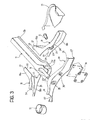
Figure 3 is an exploded perspective view of the portion of twist-beam axle shown inFigures 1 and2 ; -
Figure 4 is a plan view from above of the portion of twist-beam axle shown in the preceding figures; -
Figure 5 is a section view along line V-V inFigure 4 of the portion of twist-beam axle shown in the preceding figures; -
Figure 6 is a section view along line VI-VI inFigure 4 of the portion of twist-beam axle shown inFigures 1 to 4 ; -
Figure 7 is a section view along line VII-VII inFigure 4 of the portion of twist-beam axle shown inFigures 1 to 4 ; -
Figure 8 is a section view along line VIII-VIII inFigure 4 of the portion of twist-beam axle shown inFigures 1 to 4 ; and -
Figure 9 is a section view along line IX-IX inFigure 4 of the portion of twist-beam axle shown inFigures 1 to 4 . - In the description and the claims which follow, terms such as "longitudinal" and "transverse", "inner" and "outer", "front" and "rear" are to be understood as referred to the mounted condition on the vehicle.
- Although only one of the two symmetric parts forming the structure of the twist-beam axle in question has been described and illustrated, for clear reasons of simplicity, it is clearly understood that the non-described- part is to be considered symmetric, or substantially symmetric, to that described.
- By referring initially to
Figures 1 to 4 , a twist-beam axle for the rear suspension of a motor vehicle is generally indicated 10 and comprises acentral cross-member 11 and a pair of trailingarms 12 fixed to respectiveside end portions 11a of the cross-member (in the figures only the left-hand end is shown). Abush 13 for articulation of the twist-beam axle 10 to the vehicle body is fixed to the front end of eachtrailing arm 12, whereas amounting structure 14 for a wheel-carrier (not shown) and asheet plate 15 intended to provide a lower support surface for a spring (also, not shown) are fixed to the rear portion of thearm 12, on the transversely outer side and the transversely inner side, respectively. - The middle portion of the
cross-member 11, indicated 11b, has in its vertical plane of symmetry a cross-section of predetermined shape, in the illustrated example an omega-shape, adapted to provide the cross-member with the required elastic characteristics, in particular the compliance to torsion. Theend portions 11a of thecross-member 11 form each ahead wall 11c, downwardly inclined in the transverse direction, in which ahole 16 is provided for being passed through by atorsion bar 17 housed inside themiddle portion 11b of thecross-member 11 and fixed at its ends to the trailingarms 12. Alternatively, thetorsion bar 17 may be fixed to thehead walls 11c of theside portions 11a of the cross-member, instead of being fixed to the trailingarms 12. Moreover, themiddle portion 11b of the cross-member may assume obviously any other suitable shape, either open (as in the illustrated example) or closed. - According to the invention, each
trailing arm 12 is comprised of threesheet metal parts shells end portion 11a of thecross-member 11, and a transversely outer half-shell 20, intended to be fixed to the two inner half-shells arm 12. - Each of the two inner half-
shells first limb second limb 18b, 19b, integral with the first one, which extends essentially longitudinally or is slightly inclined outwards relative to the longitudinal direction (Figure 3 ). - Each
first limb respective end portion 11a of the cross-member, along a transverselyinner edge 21 suitably shaped to fit to thecross-member portion 11a, and to the otherfirst limb straight edges second limb 18b, 19b is arranged to be welded to the outer half-shell 20 along a pair of transverselyouter edges - In order to enable to take up possible plays between the two inner half-
shells cross-member portion 11a, the two half-shells are shaped and dimensioned in such a manner that, when they are arranged in their mounting position on to the cross-member, theirfacing edges edges - Each transversely outer half-
shell 20 has a substantially C-shaped cross-section, the upper and lower horizontal walls of which form transverselyinner edges shells torsion bar 17 is fixed to thetrailing arms 12, as in the illustrated embodiment, the vertical walls of the outer half-shells 20 haverespective holes 28 for engaging the ends of thebar 17. - As can be seen in the exploded view of
Figure 3 and in the section view ofFigure 6 , each rear inner half-shell 19 and each outer half-shell 20 have respective throughholes pin 31 is inserted for fixing the lower end of a damper (not shown). - As will be clear in the light of the preceding description, the method of production of a twist-beam axle according to the invention provides for, first of all, the manufacturing of the single parts of the axle, that is to say, the
cross-member 11, thetorsion bar 17 and the half-shells 18 to 20 intended to compose thetrailing arms 12, and then the assembling of these parts by welding the pairs of inner half-shells cross-member 11 and the outer half-shells 20 onto the pairs of inner half-shells of the respective trailing arms. - Since the
joining edges 21 to 27 of the half-shells 18 to 20 extend essentially in two dimensions, instead of three dimensions, the welding operations are easy to perform. - Naturally, the principle of the invention remaining unchanged, embodiments and manufacturing details may vary widely from those described and illustrated purely by way of non-limiting example.
Claims (9)
- Twist-beam axle for the rear suspension of a motor vehicle, comprising a central cross-member (11) and a pair of trailing arms (12) fixed to respective side end portions (11a) of the cross-member (11), wherein each trailing arm (12) comprises a pair of front and rear transversely inner half-shells (18, 19) fixed to the respective side end portion (11a) of the cross-member (11) and a transversely outer half-shell (20) securely connected to the transversely inner half-shells (18, 19) so as to form therewith a rigid body having a closed cross-section,
wherein each of the transversely inner half-shells (18, 19) comprises a first essentially transverse limb (18a, 19a) which is securely connected to the respective side end portion (11a) of the cross-member (11), and a second essentially longitudinal limb (18b, 19b), integral with the first (18a, 19a), which is securely connected to the transversely outer half-shell (20) of the trailing arm (12),
characterised in that the transversely inner half-shells (18, 19) are separate components from the cross-member (11) and are securely connected with their first essentially transverse limbs (18a, 19a) to each other and with their second essentially longitudinal limbs (18b, 19b) to the respective side end portions (11a) of the cross-member (11), and
in that the first and second limbs (18a, 18b; 19a, 19b) of the transversely inner half-shells (18, 19) and the transversely outer half-shells (20) have, at least over part of their length, a substantially C-shaped cross-section, the upper and lower horizontal walls of which form respective first joining edges (22, 23; 24, 25; 26, 27), facing two by two, for connection of the front and rear transversely inner half-shells (18, 19) to each other and to the transversely outer half-shell (20). - Twist-beam axle according to Claim 1, characterised in that the first limbs (18a, 19a) of each pair of transversely inner half-shells (18, 19) form, on the transversely inner side, respective second joining edges (21) for connection of the said half-shells to the respective side end portion (11a) of the cross-member (11).
- Twist-beam axle according to any of the preceding claims, characterised in that the half-shells (18, 19, 20) of each trailing arm (12) are securely connected to each other by welding and in that the transversely inner half-shells (18, 19) of each trailing arm (12) are securely connected to the respective side end portion (11a) of the cross-member (11) by welding.
- Twist-beam axle according to Claim 3, characterised in that in the said first facing joining edges (22, 23) for connection of the front and rear transversely inner half-shells (18, 19) to each other are spaced apart by a gap filled by a welding bead.
- Twist-beam axle according to any of the preceding claims, characterised in that the cross-member (11) has, in its vertical plane of symmetry, an omega-shaped cross-section.
- Twist-beam axle according to Claim 5, characterised in that it comprises also a torsion bar (17) housed inside the cross-member (11) and fixed at its ends to the transversely outer half-shells (20) of the trailing arms (12).
- A method for the production of a twist-beam axle (10) for the rear suspension of a motor vehicle, comprising the steps of:a) providing a cross-member (11) having side end portions (11a) adapted to engage a pair of trailing arms (12);b) providing, for each side end portion (11a) of the cross-member (11), a pair of front and rear transversely inner half-shells (18, 19) adapted to be securely connected to each other and to the side end portion (11a) of the cross-member (11), and a transversely outer half-shell (20) adapted to be securely connected to the pair of transversely inner half-shells (18, 19) so as to form therewith a rigid body of closed cross-section;c) securely connecting the pairs of transversely inner half-shells (18, 19) onto the respective side end portions (11a) of the cross-member (11);d) securely connecting the transversely outer half-shells (20) onto the respective pairs of transversely inner half-shells (18, 19).
- Method according to Claim 7, characterised in that the step b) comprises the operation of forming both the front and rear transversely inner half-shells (18, 19) in such a way that they comprise each a first essentially transverse limb (18a, 19a) adapted to be securely connected to the respective side end portion (11a) of the cross-member (11) and to the other transversely inner half-shell (19, 18) of the same trailing arm (12), and a second essentially longitudinal limb (18b, 19b), integral with the first (18a, 19a), adapted to be securely connected to the transversely outer half-shell (20) of the trailing arm (12),
wherein the said first and second limbs (18a, 18b; 19a, 19b) of each pair of transversely inner half-shells (18, 19) and each transversely outer half-shell (20) have, at least over part of their length, a substantially C-shaped cross-section, the upper and lower horizontal walls of which form respective first joining edges (22, 23; 24, 25; 26, 27), adapted to be disposed facing two by two for connection of the front and rear transversely inner half-shells (18, 19) to each other and to the transversely outer half-shell (20), and
wherein the first limbs (18a, 19a) of each pair of transversely inner half-shells (18, 19) form, on the transversely inner side, respective second joining edges (21) for connection of the transversely inner half-shells to the respective side end portion (11a) of the cross-member (11). - Method according to Claim 8, characterised in that the steps c) and d) comprise the operation of welding the said first and second joining edges (22, 23; 24, 25; 26, 27; 21).
Applications Claiming Priority (3)
| Application Number | Priority Date | Filing Date | Title |
|---|---|---|---|
| IT000959A ITTO20020959A1 (en) | 2002-11-07 | 2002-11-07 | TWIST BRIDGE FOR THE REAR SUSPENSION OF A |
| ITTO20020959 | 2002-11-07 | ||
| PCT/EP2003/012337 WO2004041564A1 (en) | 2002-11-07 | 2003-11-05 | Twist-beam axle for the rear suspension of a motor vehicle and method for its production |
Publications (2)
| Publication Number | Publication Date |
|---|---|
| EP1567371A1 EP1567371A1 (en) | 2005-08-31 |
| EP1567371B1 true EP1567371B1 (en) | 2008-08-06 |
Family
ID=32310197
Family Applications (1)
| Application Number | Title | Priority Date | Filing Date |
|---|---|---|---|
| EP03772307A Expired - Lifetime EP1567371B1 (en) | 2002-11-07 | 2003-11-05 | Twist-beam axle for the rear suspension of a motor vehicle and method for its production |
Country Status (10)
| Country | Link |
|---|---|
| US (1) | US7204498B2 (en) |
| EP (1) | EP1567371B1 (en) |
| AT (1) | ATE403562T1 (en) |
| AU (1) | AU2003279360A1 (en) |
| BR (1) | BR0315468B1 (en) |
| DE (1) | DE60322737D1 (en) |
| ES (1) | ES2312827T3 (en) |
| IT (1) | ITTO20020959A1 (en) |
| PL (1) | PL213204B1 (en) |
| WO (1) | WO2004041564A1 (en) |
Families Citing this family (35)
| Publication number | Priority date | Publication date | Assignee | Title |
|---|---|---|---|---|
| DE102004055100B4 (en) * | 2004-11-15 | 2011-07-14 | Benteler Automobiltechnik GmbH, 33102 | Axle construction for a motor vehicle |
| FR2878786B1 (en) * | 2004-12-08 | 2007-02-23 | Auto Chassis Internat Snc Snc | FLEXIBLE AXLE COMPRISING A TROPEZOIDAL SECTION RAIL, TRAVERSE, VEHICLE AND METHOD FOR MANUFACTURING THE SAME |
| US20060158023A1 (en) * | 2005-01-14 | 2006-07-20 | The Boler Company | Continuous radius axle and fabricated spindle assembly |
| EP1832448A4 (en) * | 2005-03-04 | 2008-04-16 | F Tech Inc | TORSION LENGTH SUSPENSION |
| FR2888530B1 (en) * | 2005-07-13 | 2008-10-24 | Auto Chassis Internat Snc Snc | FLEXIBLE AXLE OF A MOTOR VEHICLE, COMPRISING AN OPEN SECTION CROSS SECTION WITH FLANKS INTRODUCING NON-RECTILINE STITCHES, TRAVERSE AND CORRESPONDING VEHICLE |
| US7556272B2 (en) * | 2005-09-06 | 2009-07-07 | Gm Global Technology Operations, Inc. | Twist axle suspensions |
| JP4193837B2 (en) * | 2005-11-04 | 2008-12-10 | トヨタ自動車株式会社 | Trailing arm suspension structure and axle carrier |
| JP4344352B2 (en) * | 2005-12-05 | 2009-10-14 | 本田技研工業株式会社 | Torsion beam suspension |
| JP4301307B2 (en) * | 2007-03-01 | 2009-07-22 | トヨタ自動車株式会社 | Torsion beam suspension |
| WO2009077810A1 (en) * | 2007-12-18 | 2009-06-25 | Renault Trucks | Rear modular suspension for a motorized heavy goods vehicle |
| DE102008013183B4 (en) * | 2008-03-07 | 2012-08-30 | Benteler Automobiltechnik Gmbh | Beam axle |
| KR20100029463A (en) * | 2008-09-08 | 2010-03-17 | 현대자동차주식회사 | Torsion beam type suspension system of vehicle |
| US7946600B2 (en) * | 2008-09-17 | 2011-05-24 | Honda Motor Co., Ltd. | Torsion beam type rear wheel suspension system |
| DE102009024831A1 (en) * | 2009-06-13 | 2010-12-16 | Volkswagen Ag | Twist-beam rear axle for motor vehicle, has two joint elements connected to rear end sections of trailing links, where profile cross-sections of end sections of crossbeam are completely enclosed by corresponding retainers at joint elements |
| FR2949995B1 (en) * | 2009-09-11 | 2011-12-16 | Peugeot Citroen Automobiles Sa | TUBULAR STRUCTURE FOR CARRYING OUT, IN PARTICULAR, AN AXLE OF A ROLLING GEAR OF A MOTOR VEHICLE |
| FR2949996B1 (en) * | 2009-09-11 | 2012-10-05 | Peugeot Citroen Automobiles Sa | MODULAR AXLE FOR A VEHICLE RAILWAY, IN PARTICULAR FOR A MOTOR VEHICLE |
| CN103097152B (en) * | 2010-07-23 | 2015-08-05 | 本田技研工业株式会社 | Torsional beam type suspension device |
| US8322736B2 (en) | 2011-02-18 | 2012-12-04 | Honda Motor Co., Ltd. | Swing arm assembly |
| FR2972961A1 (en) * | 2011-03-24 | 2012-09-28 | Peugeot Citroen Automobiles Sa | Mounting support for supporting axle of wheel of car, has vertical plates fixed on one another to form U-shaped wheel supporting part, where thickness of central part of supporting part is doubled compared to side parts of supporting part |
| DE102011079979A1 (en) * | 2011-07-28 | 2013-01-31 | Zf Friedrichshafen Ag | Beam axle |
| DE102011080036A1 (en) * | 2011-07-28 | 2013-01-31 | Zf Friedrichshafen Ag | Radnahe drive unit for a motor vehicle |
| DE102011052339B4 (en) * | 2011-08-01 | 2020-07-09 | Benteler Automobiltechnik Gmbh | Twist beam axle |
| DE102012020612A1 (en) * | 2012-10-19 | 2014-04-24 | Audi Ag | Axle carrier for a motor vehicle |
| CN106660422B (en) * | 2014-03-27 | 2019-09-03 | 株式会社万 | torsion beam suspension |
| EP3124297B1 (en) * | 2014-03-27 | 2020-03-18 | Yorozu Corporation | Torsion beam suspension |
| DE102014105904A1 (en) * | 2014-04-28 | 2015-10-29 | Benteler Automobiltechnik Gmbh | Twist-beam axle and method for producing a torsion profile |
| DE102014107953A1 (en) * | 2014-06-05 | 2015-12-17 | Benteler Automobiltechnik Gmbh | Built wheel carrier |
| WO2016086291A1 (en) * | 2014-12-03 | 2016-06-09 | Magna International Inc. | Vehicle twist axle assembly |
| DE102015213357B4 (en) * | 2015-07-16 | 2018-02-08 | Zf Friedrichshafen Ag | Driven torsion beam axle with a transverse profile and each end of the transverse profile associated trailing arms |
| WO2017086898A2 (en) * | 2015-11-16 | 2017-05-26 | Coskunoz Metal Form Makina Endustri Ve Ticaret Anonim Sirketi | Production method of an axle mount bracket |
| EP3192724B1 (en) * | 2016-01-14 | 2019-04-03 | FCA Italy S.p.A. | Motor-vehicle body structure |
| EP3484734A4 (en) * | 2016-07-15 | 2020-03-18 | Magna International Inc. | VEHICLE TORSION AXLE ASSEMBLY |
| US11084371B2 (en) * | 2017-01-10 | 2021-08-10 | Showa Corporation | Motor drive device |
| JP6875679B2 (en) * | 2017-03-27 | 2021-05-26 | マツダ株式会社 | Rear suspension structure of automobile |
| DE102018205877B3 (en) * | 2018-04-18 | 2019-10-24 | Ford Global Technologies, Llc | Axle for a vehicle |
Family Cites Families (21)
| Publication number | Priority date | Publication date | Assignee | Title |
|---|---|---|---|---|
| DE2103399C2 (en) * | 1971-01-26 | 1982-07-15 | Audi Nsu Auto Union Ag, 7107 Neckarsulm | Wheel suspension for non-driven rear wheels of motor vehicles |
| DE2735939C2 (en) * | 1977-08-10 | 1979-10-04 | Volkswagenwerk Ag, 3180 Wolfsburg | Axle assembly for motor vehicles, especially cars |
| US4165099A (en) * | 1977-11-28 | 1979-08-21 | Chrysler Corporation | Rear suspension apparatus for a motor vehicle |
| US4165098A (en) | 1977-11-28 | 1979-08-21 | Chrysler Corporation | Rear suspension apparatus for a motor vehicle |
| FR2487262A1 (en) * | 1980-07-22 | 1982-01-29 | Fiat Auto Spa | REAR AXLE FOR MOTOR VEHICLE |
| JPS5890814U (en) * | 1981-12-14 | 1983-06-20 | マツダ株式会社 | Automobile rear wheel suspension system |
| JPS58105815A (en) * | 1981-12-17 | 1983-06-23 | Mazda Motor Corp | Rear wheel suspension for automobile |
| US5324073A (en) * | 1990-08-10 | 1994-06-28 | Benteler Industries, Inc. | Tuned twist beam axle |
| US5409255A (en) * | 1990-08-10 | 1995-04-25 | Benteler Industries, Inc. | Twist beam axle |
| FR2712534B3 (en) * | 1993-11-16 | 1996-02-09 | Lorraine Laminage | Rear axle of semi-rigid axle vehicle. |
| US6099084A (en) * | 1994-11-25 | 2000-08-08 | Vaw Aluminium Ag | Twist beam axle and method of producing same |
| DE4441971A1 (en) * | 1994-11-25 | 1996-05-30 | Vaw Ver Aluminium Werke Ag | Motor vehicle rear axle and method for its production |
| FR2734207B1 (en) * | 1995-05-19 | 1997-07-25 | Vallourec Vitry | SEMI-RIGID AXLE FOR VEHICLE |
| DE19649076B4 (en) * | 1996-11-27 | 2006-10-05 | Benteler Ag | Method for producing a torsion beam axle for motor vehicles and torsion beam axle |
| DE19707643C1 (en) * | 1997-02-26 | 1998-12-24 | Ford Global Tech Inc | Twist-beam rear axle for motor vehicles |
| JPH10236123A (en) * | 1997-02-27 | 1998-09-08 | Toyota Motor Corp | Torsion beam suspension |
| JPH1111133A (en) * | 1997-06-25 | 1999-01-19 | Mazda Motor Corp | Vehicle stabilizer device and assembling method thereof |
| DE29720207U1 (en) * | 1997-11-14 | 1998-01-02 | Benteler Ag, 33104 Paderborn | Twist beam axle for motor vehicles |
| JP3604951B2 (en) * | 1999-05-17 | 2004-12-22 | ダイハツ工業株式会社 | Trailing arm suspension |
| US6523841B2 (en) * | 2000-05-31 | 2003-02-25 | Benteler Ag | Twist-beam axle for motor vehicles |
| GB0021716D0 (en) * | 2000-09-05 | 2000-10-18 | Meritor Heavy Vehicle Sys Ltd | Vehicle suspension axle wrap |
-
2002
- 2002-11-07 IT IT000959A patent/ITTO20020959A1/en unknown
-
2003
- 2003-11-05 ES ES03772307T patent/ES2312827T3/en not_active Expired - Lifetime
- 2003-11-05 AU AU2003279360A patent/AU2003279360A1/en not_active Abandoned
- 2003-11-05 BR BRPI0315468-8A patent/BR0315468B1/en not_active IP Right Cessation
- 2003-11-05 WO PCT/EP2003/012337 patent/WO2004041564A1/en not_active Ceased
- 2003-11-05 PL PL376775A patent/PL213204B1/en unknown
- 2003-11-05 DE DE60322737T patent/DE60322737D1/en not_active Expired - Lifetime
- 2003-11-05 EP EP03772307A patent/EP1567371B1/en not_active Expired - Lifetime
- 2003-11-05 AT AT03772307T patent/ATE403562T1/en not_active IP Right Cessation
- 2003-11-05 US US10/534,017 patent/US7204498B2/en not_active Expired - Lifetime
Also Published As
| Publication number | Publication date |
|---|---|
| US7204498B2 (en) | 2007-04-17 |
| AU2003279360A1 (en) | 2004-06-07 |
| ATE403562T1 (en) | 2008-08-15 |
| PL213204B1 (en) | 2013-01-31 |
| BR0315468B1 (en) | 2013-05-28 |
| ES2312827T3 (en) | 2009-03-01 |
| US20060131829A1 (en) | 2006-06-22 |
| WO2004041564A1 (en) | 2004-05-21 |
| ITTO20020959A1 (en) | 2004-05-08 |
| PL376775A1 (en) | 2006-01-09 |
| EP1567371A1 (en) | 2005-08-31 |
| DE60322737D1 (en) | 2008-09-18 |
| BR0315468A (en) | 2005-08-23 |
Similar Documents
| Publication | Publication Date | Title |
|---|---|---|
| US7204498B2 (en) | Twist-beam axle for the rear suspension of a motor vehicle and method for its production | |
| US5810377A (en) | Fabricated steer axle | |
| EP2116401B1 (en) | Torsion beam type suspension | |
| CN1726139B (en) | Cast or forged suspension trailing arms and suspension assemblies having such suspension trailing arms | |
| EP2310217B1 (en) | Cross-member for a rear twist-beam axle suspension for a motor vechicle and method for its production | |
| US4432564A (en) | Rear suspension assembly for motor vehicles | |
| EP2222489B1 (en) | Cross-member for a twist-beam axle rear suspension for a motor vehicle | |
| CA2909707A1 (en) | Twist beam with joined inner and outer parts | |
| CN102317093A (en) | Suspension arm for a motor vehicle wheel suspension | |
| US7871093B2 (en) | Torsion beam suspension | |
| GB2297733A (en) | Trailing arm suspension structure for vehicle | |
| US10086874B2 (en) | Modular vehicle platform and related methods | |
| JP3551039B2 (en) | Torsion beam suspension | |
| EP2075146B1 (en) | Twist-beam rear axle and method for producing a cross member | |
| EP0752933B1 (en) | Trailing arm suspension | |
| JP2000272535A (en) | Vehicle subframe structure | |
| CA2376602C (en) | Control rod | |
| JP7116788B2 (en) | Assembled axle seat assembly | |
| JPH06122307A (en) | Structure for trailing arm type suspension | |
| KR20050101899A (en) | Coupled torsion beam suspension of a vehicle | |
| JPH06262920A (en) | Link fitting structure | |
| CA2187664C (en) | Trailing arm suspension | |
| JPH0986126A (en) | knuckle | |
| MXPA97006859A (en) | Sold steering axle | |
| JP2001039134A (en) | Trailing arm type suspension |
Legal Events
| Date | Code | Title | Description |
|---|---|---|---|
| PUAI | Public reference made under article 153(3) epc to a published international application that has entered the european phase |
Free format text: ORIGINAL CODE: 0009012 |
|
| 17P | Request for examination filed |
Effective date: 20050606 |
|
| AK | Designated contracting states |
Kind code of ref document: A1 Designated state(s): AT BE BG CH CY CZ DE DK EE ES FI FR GB GR HU IE IT LI LU MC NL PT RO SE SI SK TR |
|
| AX | Request for extension of the european patent |
Extension state: AL LT LV MK |
|
| DAX | Request for extension of the european patent (deleted) | ||
| GRAP | Despatch of communication of intention to grant a patent |
Free format text: ORIGINAL CODE: EPIDOSNIGR1 |
|
| RIN1 | Information on inventor provided before grant (corrected) |
Inventor name: BUSSOLINO, DANIELE Inventor name: ALESSO, GUIDO, SEBASTIANO |
|
| RAP1 | Party data changed (applicant data changed or rights of an application transferred) |
Owner name: SISTEMI SOSPENSIONI S.P.A. |
|
| RAP1 | Party data changed (applicant data changed or rights of an application transferred) |
Owner name: SISTEMI SOSPENSIONI S.P.A. |
|
| GRAS | Grant fee paid |
Free format text: ORIGINAL CODE: EPIDOSNIGR3 |
|
| GRAA | (expected) grant |
Free format text: ORIGINAL CODE: 0009210 |
|
| AK | Designated contracting states |
Kind code of ref document: B1 Designated state(s): AT BE BG CH CY CZ DE DK EE ES FI FR GB GR HU IE IT LI LU MC NL PT RO SE SI SK TR |
|
| REG | Reference to a national code |
Ref country code: GB Ref legal event code: FG4D |
|
| REG | Reference to a national code |
Ref country code: CH Ref legal event code: EP |
|
| REG | Reference to a national code |
Ref country code: IE Ref legal event code: FG4D |
|
| REF | Corresponds to: |
Ref document number: 60322737 Country of ref document: DE Date of ref document: 20080918 Kind code of ref document: P |
|
| PG25 | Lapsed in a contracting state [announced via postgrant information from national office to epo] |
Ref country code: NL Free format text: LAPSE BECAUSE OF FAILURE TO SUBMIT A TRANSLATION OF THE DESCRIPTION OR TO PAY THE FEE WITHIN THE PRESCRIBED TIME-LIMIT Effective date: 20080806 |
|
| PG25 | Lapsed in a contracting state [announced via postgrant information from national office to epo] |
Ref country code: SI Free format text: LAPSE BECAUSE OF FAILURE TO SUBMIT A TRANSLATION OF THE DESCRIPTION OR TO PAY THE FEE WITHIN THE PRESCRIBED TIME-LIMIT Effective date: 20080806 Ref country code: FI Free format text: LAPSE BECAUSE OF FAILURE TO SUBMIT A TRANSLATION OF THE DESCRIPTION OR TO PAY THE FEE WITHIN THE PRESCRIBED TIME-LIMIT Effective date: 20080806 Ref country code: AT Free format text: LAPSE BECAUSE OF FAILURE TO SUBMIT A TRANSLATION OF THE DESCRIPTION OR TO PAY THE FEE WITHIN THE PRESCRIBED TIME-LIMIT Effective date: 20080806 |
|
| REG | Reference to a national code |
Ref country code: ES Ref legal event code: FG2A Ref document number: 2312827 Country of ref document: ES Kind code of ref document: T3 |
|
| PG25 | Lapsed in a contracting state [announced via postgrant information from national office to epo] |
Ref country code: BE Free format text: LAPSE BECAUSE OF FAILURE TO SUBMIT A TRANSLATION OF THE DESCRIPTION OR TO PAY THE FEE WITHIN THE PRESCRIBED TIME-LIMIT Effective date: 20080806 |
|
| PG25 | Lapsed in a contracting state [announced via postgrant information from national office to epo] |
Ref country code: DK Free format text: LAPSE BECAUSE OF FAILURE TO SUBMIT A TRANSLATION OF THE DESCRIPTION OR TO PAY THE FEE WITHIN THE PRESCRIBED TIME-LIMIT Effective date: 20080806 Ref country code: BG Free format text: LAPSE BECAUSE OF FAILURE TO SUBMIT A TRANSLATION OF THE DESCRIPTION OR TO PAY THE FEE WITHIN THE PRESCRIBED TIME-LIMIT Effective date: 20081106 |
|
| PG25 | Lapsed in a contracting state [announced via postgrant information from national office to epo] |
Ref country code: SK Free format text: LAPSE BECAUSE OF FAILURE TO SUBMIT A TRANSLATION OF THE DESCRIPTION OR TO PAY THE FEE WITHIN THE PRESCRIBED TIME-LIMIT Effective date: 20080806 Ref country code: PT Free format text: LAPSE BECAUSE OF FAILURE TO SUBMIT A TRANSLATION OF THE DESCRIPTION OR TO PAY THE FEE WITHIN THE PRESCRIBED TIME-LIMIT Effective date: 20090106 Ref country code: RO Free format text: LAPSE BECAUSE OF FAILURE TO SUBMIT A TRANSLATION OF THE DESCRIPTION OR TO PAY THE FEE WITHIN THE PRESCRIBED TIME-LIMIT Effective date: 20080806 |
|
| PLBE | No opposition filed within time limit |
Free format text: ORIGINAL CODE: 0009261 |
|
| STAA | Information on the status of an ep patent application or granted ep patent |
Free format text: STATUS: NO OPPOSITION FILED WITHIN TIME LIMIT |
|
| PG25 | Lapsed in a contracting state [announced via postgrant information from national office to epo] |
Ref country code: MC Free format text: LAPSE BECAUSE OF NON-PAYMENT OF DUE FEES Effective date: 20081130 |
|
| REG | Reference to a national code |
Ref country code: CH Ref legal event code: PL |
|
| 26N | No opposition filed |
Effective date: 20090507 |
|
| PG25 | Lapsed in a contracting state [announced via postgrant information from national office to epo] |
Ref country code: EE Free format text: LAPSE BECAUSE OF FAILURE TO SUBMIT A TRANSLATION OF THE DESCRIPTION OR TO PAY THE FEE WITHIN THE PRESCRIBED TIME-LIMIT Effective date: 20080806 |
|
| REG | Reference to a national code |
Ref country code: IE Ref legal event code: MM4A |
|
| PG25 | Lapsed in a contracting state [announced via postgrant information from national office to epo] |
Ref country code: IE Free format text: LAPSE BECAUSE OF NON-PAYMENT OF DUE FEES Effective date: 20081105 Ref country code: CH Free format text: LAPSE BECAUSE OF NON-PAYMENT OF DUE FEES Effective date: 20081130 Ref country code: LI Free format text: LAPSE BECAUSE OF NON-PAYMENT OF DUE FEES Effective date: 20081130 |
|
| PG25 | Lapsed in a contracting state [announced via postgrant information from national office to epo] |
Ref country code: SE Free format text: LAPSE BECAUSE OF FAILURE TO SUBMIT A TRANSLATION OF THE DESCRIPTION OR TO PAY THE FEE WITHIN THE PRESCRIBED TIME-LIMIT Effective date: 20081106 |
|
| PG25 | Lapsed in a contracting state [announced via postgrant information from national office to epo] |
Ref country code: CY Free format text: LAPSE BECAUSE OF FAILURE TO SUBMIT A TRANSLATION OF THE DESCRIPTION OR TO PAY THE FEE WITHIN THE PRESCRIBED TIME-LIMIT Effective date: 20080806 Ref country code: LU Free format text: LAPSE BECAUSE OF NON-PAYMENT OF DUE FEES Effective date: 20081105 |
|
| PG25 | Lapsed in a contracting state [announced via postgrant information from national office to epo] |
Ref country code: GR Free format text: LAPSE BECAUSE OF FAILURE TO SUBMIT A TRANSLATION OF THE DESCRIPTION OR TO PAY THE FEE WITHIN THE PRESCRIBED TIME-LIMIT Effective date: 20081107 |
|
| PGFP | Annual fee paid to national office [announced via postgrant information from national office to epo] |
Ref country code: ES Payment date: 20141103 Year of fee payment: 12 Ref country code: GB Payment date: 20141024 Year of fee payment: 12 Ref country code: CZ Payment date: 20141027 Year of fee payment: 12 |
|
| PGFP | Annual fee paid to national office [announced via postgrant information from national office to epo] |
Ref country code: HU Payment date: 20141128 Year of fee payment: 12 |
|
| REG | Reference to a national code |
Ref country code: FR Ref legal event code: PLFP Year of fee payment: 13 |
|
| GBPC | Gb: european patent ceased through non-payment of renewal fee |
Effective date: 20151105 |
|
| PG25 | Lapsed in a contracting state [announced via postgrant information from national office to epo] |
Ref country code: CZ Free format text: LAPSE BECAUSE OF NON-PAYMENT OF DUE FEES Effective date: 20151105 |
|
| PG25 | Lapsed in a contracting state [announced via postgrant information from national office to epo] |
Ref country code: HU Free format text: LAPSE BECAUSE OF NON-PAYMENT OF DUE FEES Effective date: 20151106 |
|
| REG | Reference to a national code |
Ref country code: FR Ref legal event code: PLFP Year of fee payment: 14 |
|
| PG25 | Lapsed in a contracting state [announced via postgrant information from national office to epo] |
Ref country code: GB Free format text: LAPSE BECAUSE OF NON-PAYMENT OF DUE FEES Effective date: 20151105 |
|
| PG25 | Lapsed in a contracting state [announced via postgrant information from national office to epo] |
Ref country code: ES Free format text: LAPSE BECAUSE OF NON-PAYMENT OF DUE FEES Effective date: 20151106 |
|
| REG | Reference to a national code |
Ref country code: FR Ref legal event code: PLFP Year of fee payment: 15 |
|
| REG | Reference to a national code |
Ref country code: ES Ref legal event code: FD2A Effective date: 20180626 |
|
| REG | Reference to a national code |
Ref country code: FR Ref legal event code: PLFP Year of fee payment: 16 |
|
| PGFP | Annual fee paid to national office [announced via postgrant information from national office to epo] |
Ref country code: TR Payment date: 20191104 Year of fee payment: 17 |
|
| PG25 | Lapsed in a contracting state [announced via postgrant information from national office to epo] |
Ref country code: TR Free format text: LAPSE BECAUSE OF NON-PAYMENT OF DUE FEES Effective date: 20201105 |
|
| PGFP | Annual fee paid to national office [announced via postgrant information from national office to epo] |
Ref country code: FR Payment date: 20221021 Year of fee payment: 20 |
|
| PGFP | Annual fee paid to national office [announced via postgrant information from national office to epo] |
Ref country code: IT Payment date: 20221020 Year of fee payment: 20 Ref country code: DE Payment date: 20220616 Year of fee payment: 20 |
|
| REG | Reference to a national code |
Ref country code: DE Ref legal event code: R071 Ref document number: 60322737 Country of ref document: DE |