EP1566678A1 - Riegel zur Fixierung des Segments eines optischen Weltraumteleskops - Google Patents
Riegel zur Fixierung des Segments eines optischen Weltraumteleskops Download PDFInfo
- Publication number
- EP1566678A1 EP1566678A1 EP05010787A EP05010787A EP1566678A1 EP 1566678 A1 EP1566678 A1 EP 1566678A1 EP 05010787 A EP05010787 A EP 05010787A EP 05010787 A EP05010787 A EP 05010787A EP 1566678 A1 EP1566678 A1 EP 1566678A1
- Authority
- EP
- European Patent Office
- Prior art keywords
- petal
- latch
- latch assembly
- recited
- assembly
- Prior art date
- Legal status (The legal status is an assumption and is not a legal conclusion. Google has not performed a legal analysis and makes no representation as to the accuracy of the status listed.)
- Granted
Links
- 230000003287 optical effect Effects 0.000 title claims abstract description 19
- 229910052581 Si3N4 Inorganic materials 0.000 claims description 8
- HQVNEWCFYHHQES-UHFFFAOYSA-N silicon nitride Chemical compound N12[Si]34N5[Si]62N3[Si]51N64 HQVNEWCFYHHQES-UHFFFAOYSA-N 0.000 claims description 8
- 239000004810 polytetrafluoroethylene Substances 0.000 claims description 6
- 229920001343 polytetrafluoroethylene Polymers 0.000 claims description 6
- 230000000712 assembly Effects 0.000 description 7
- 238000000429 assembly Methods 0.000 description 7
- 230000008602 contraction Effects 0.000 description 5
- 238000005461 lubrication Methods 0.000 description 3
- 230000000717 retained effect Effects 0.000 description 3
- 230000007704 transition Effects 0.000 description 3
- 244000258271 Galium odoratum Species 0.000 description 2
- 235000008526 Galium odoratum Nutrition 0.000 description 2
- 230000008878 coupling Effects 0.000 description 2
- 238000010168 coupling process Methods 0.000 description 2
- 238000005859 coupling reaction Methods 0.000 description 2
- OKTJSMMVPCPJKN-UHFFFAOYSA-N Carbon Chemical compound [C] OKTJSMMVPCPJKN-UHFFFAOYSA-N 0.000 description 1
- VYPSYNLAJGMNEJ-UHFFFAOYSA-N Silicium dioxide Chemical compound O=[Si]=O VYPSYNLAJGMNEJ-UHFFFAOYSA-N 0.000 description 1
- 230000009286 beneficial effect Effects 0.000 description 1
- 229910052799 carbon Inorganic materials 0.000 description 1
- 230000000295 complement effect Effects 0.000 description 1
- 239000002131 composite material Substances 0.000 description 1
- 238000010276 construction Methods 0.000 description 1
- 239000005350 fused silica glass Substances 0.000 description 1
- 238000004519 manufacturing process Methods 0.000 description 1
- 230000013011 mating Effects 0.000 description 1
- 238000012986 modification Methods 0.000 description 1
- 230000004048 modification Effects 0.000 description 1
- 230000000087 stabilizing effect Effects 0.000 description 1
Images


Classifications
-
- F—MECHANICAL ENGINEERING; LIGHTING; HEATING; WEAPONS; BLASTING
- F16—ENGINEERING ELEMENTS AND UNITS; GENERAL MEASURES FOR PRODUCING AND MAINTAINING EFFECTIVE FUNCTIONING OF MACHINES OR INSTALLATIONS; THERMAL INSULATION IN GENERAL
- F16C—SHAFTS; FLEXIBLE SHAFTS; ELEMENTS OR CRANKSHAFT MECHANISMS; ROTARY BODIES OTHER THAN GEARING ELEMENTS; BEARINGS
- F16C33/00—Parts of bearings; Special methods for making bearings or parts thereof
- F16C33/30—Parts of ball or roller bearings
- F16C33/32—Balls
-
- B—PERFORMING OPERATIONS; TRANSPORTING
- B64—AIRCRAFT; AVIATION; COSMONAUTICS
- B64G—COSMONAUTICS; VEHICLES OR EQUIPMENT THEREFOR
- B64G1/00—Cosmonautic vehicles
- B64G1/22—Parts of, or equipment specially adapted for fitting in or to, cosmonautic vehicles
- B64G1/222—Parts of, or equipment specially adapted for fitting in or to, cosmonautic vehicles for deploying structures between a stowed and deployed state
- B64G1/2228—Parts of, or equipment specially adapted for fitting in or to, cosmonautic vehicles for deploying structures between a stowed and deployed state characterised by the hold-down or release mechanisms
-
- B—PERFORMING OPERATIONS; TRANSPORTING
- B64—AIRCRAFT; AVIATION; COSMONAUTICS
- B64G—COSMONAUTICS; VEHICLES OR EQUIPMENT THEREFOR
- B64G1/00—Cosmonautic vehicles
- B64G1/22—Parts of, or equipment specially adapted for fitting in or to, cosmonautic vehicles
- B64G1/222—Parts of, or equipment specially adapted for fitting in or to, cosmonautic vehicles for deploying structures between a stowed and deployed state
- B64G1/2229—Parts of, or equipment specially adapted for fitting in or to, cosmonautic vehicles for deploying structures between a stowed and deployed state characterised by the deployment actuating mechanism
-
- F—MECHANICAL ENGINEERING; LIGHTING; HEATING; WEAPONS; BLASTING
- F16—ENGINEERING ELEMENTS AND UNITS; GENERAL MEASURES FOR PRODUCING AND MAINTAINING EFFECTIVE FUNCTIONING OF MACHINES OR INSTALLATIONS; THERMAL INSULATION IN GENERAL
- F16C—SHAFTS; FLEXIBLE SHAFTS; ELEMENTS OR CRANKSHAFT MECHANISMS; ROTARY BODIES OTHER THAN GEARING ELEMENTS; BEARINGS
- F16C31/00—Bearings for parts which both rotate and move linearly
- F16C31/04—Ball or roller bearings
-
- F—MECHANICAL ENGINEERING; LIGHTING; HEATING; WEAPONS; BLASTING
- F16—ENGINEERING ELEMENTS AND UNITS; GENERAL MEASURES FOR PRODUCING AND MAINTAINING EFFECTIVE FUNCTIONING OF MACHINES OR INSTALLATIONS; THERMAL INSULATION IN GENERAL
- F16C—SHAFTS; FLEXIBLE SHAFTS; ELEMENTS OR CRANKSHAFT MECHANISMS; ROTARY BODIES OTHER THAN GEARING ELEMENTS; BEARINGS
- F16C33/00—Parts of bearings; Special methods for making bearings or parts thereof
- F16C33/30—Parts of ball or roller bearings
- F16C33/38—Ball cages
- F16C33/40—Ball cages for multiple rows of balls
-
- F—MECHANICAL ENGINEERING; LIGHTING; HEATING; WEAPONS; BLASTING
- F16—ENGINEERING ELEMENTS AND UNITS; GENERAL MEASURES FOR PRODUCING AND MAINTAINING EFFECTIVE FUNCTIONING OF MACHINES OR INSTALLATIONS; THERMAL INSULATION IN GENERAL
- F16C—SHAFTS; FLEXIBLE SHAFTS; ELEMENTS OR CRANKSHAFT MECHANISMS; ROTARY BODIES OTHER THAN GEARING ELEMENTS; BEARINGS
- F16C33/00—Parts of bearings; Special methods for making bearings or parts thereof
- F16C33/30—Parts of ball or roller bearings
- F16C33/46—Cages for rollers or needles
- F16C33/56—Selection of substances
-
- G—PHYSICS
- G02—OPTICS
- G02B—OPTICAL ELEMENTS, SYSTEMS OR APPARATUS
- G02B7/00—Mountings, adjusting means, or light-tight connections, for optical elements
- G02B7/18—Mountings, adjusting means, or light-tight connections, for optical elements for prisms; for mirrors
- G02B7/182—Mountings, adjusting means, or light-tight connections, for optical elements for prisms; for mirrors for mirrors
- G02B7/183—Mountings, adjusting means, or light-tight connections, for optical elements for prisms; for mirrors for mirrors specially adapted for very large mirrors, e.g. for astronomy, or solar concentrators
-
- B—PERFORMING OPERATIONS; TRANSPORTING
- B64—AIRCRAFT; AVIATION; COSMONAUTICS
- B64G—COSMONAUTICS; VEHICLES OR EQUIPMENT THEREFOR
- B64G1/00—Cosmonautic vehicles
- B64G1/22—Parts of, or equipment specially adapted for fitting in or to, cosmonautic vehicles
- B64G1/66—Arrangements or adaptations of apparatus or instruments, not otherwise provided for
-
- F—MECHANICAL ENGINEERING; LIGHTING; HEATING; WEAPONS; BLASTING
- F16—ENGINEERING ELEMENTS AND UNITS; GENERAL MEASURES FOR PRODUCING AND MAINTAINING EFFECTIVE FUNCTIONING OF MACHINES OR INSTALLATIONS; THERMAL INSULATION IN GENERAL
- F16C—SHAFTS; FLEXIBLE SHAFTS; ELEMENTS OR CRANKSHAFT MECHANISMS; ROTARY BODIES OTHER THAN GEARING ELEMENTS; BEARINGS
- F16C2326/00—Articles relating to transporting
- F16C2326/47—Cosmonautic vehicles, i.e. bearings adapted for use in outer-space
Definitions
- the subject invention relates to a system for deploying the petals of a sectored mirror of an optical space telescope, and more particularly, to a set of hinges for independently connecting a petal of the sectored mirror to the central hub of the sectored mirror and to a latch mechanism for securing the hinged petal to the central hub in a deployed position.
- the success of the Hubble Space Telescope has spurred the development of other space-based astronomical observatories, including some incorporating a large diameter primary mirror.
- NST Next Generation Space Telescope
- the subject invention is directed to a new and useful system for deploying the petals of a sectored mirror assembly of an optical space telescope.
- the mirror assembly includes a central hub and a plurality of petals disposed about the periphery of the central hub. Each petal has a petal root that is independently hinged to the central hub of the mirror assembly.
- the petal deployment system of the subject invention includes a first hinge assembly having a root mount secured to a petal root and a hub mount secured the central hub.
- the first hinge assembly is adapted and configured to afford the petal associated therewith freedom of rotation about a petal hinge axis.
- the petal deployment system further includes a second hinge assembly having a root mount secured to the petal root and a hub mount secured to the central hub.
- the second hinge assembly is adapted and configured to afford the petal associated therewith freedom of rotation about the petal hinge axis, as well as freedom to expand and contract thermally, and move rigidly along the petal hinge axis in a frictionless, unconstrained manner.
- the petal deployment system further includes a latch assembly including a clevis secured to the petal root at a location spaced from the hinge axis and a pair of laterally opposed latches that are operatively associated with the central hub for engaging the clevis upon rotation of the petal about the hinge axis from a stowed position to a deployed position.
- a latch assembly including a clevis secured to the petal root at a location spaced from the hinge axis and a pair of laterally opposed latches that are operatively associated with the central hub for engaging the clevis upon rotation of the petal about the hinge axis from a stowed position to a deployed position.
- the first hinge assembly includes a first hinge shaft disposed on the petal hinge axis.
- the first hinge shaft is secured to the root mount of the first hinge assembly, and supports a plurality of axially spaced apart angular contact bearings.
- the angular contact bearings are formed from silicon nitride, do not require lubrication and are housed within the hub mount of the first hinge assembly.
- the second hinge assembly includes a second hinge shaft disposed on the petal hinge axis.
- the second hinge shaft is supported by the root mount of the second hinge assembly, and is disposed within a cylindrical bearing cage.
- the bearing cage is formed from PTFE and retains a plurality of ball bearings.
- the ball bearings are formed from silicon nitride and do not require lubrication.
- the bearing cage is disposed between an inner bearing race and an outer bearing race, and is housed within the hub mount of the second hinge assembly.
- the latch assembly of the subject invention is adapted and configured to afford the petal associated therewith freedom to expand and contract thermally, and move rigidly along a latch axis extending parallel to the hinge axis in a frictionless, unconstrained manner.
- Each laterally opposed latch of the latch assembly includes a latch shaft mounted for linear movement along the latch axis.
- the clevis of the latch assembly defines a reception aperture for receiving the laterally opposed latch shafts, and an actuator is operatively associated with each latch for moving the latch shaft thereof into engagement with the clevis.
- Each latch shaft is disposed within a cylindrical bearing cage, and each bearing cage is formed from PTFE.
- Each bearing cage retains a plurality of ball bearings formed from silicon nitride, and is disposed between an inner bearing race and an outer bearing race.
- Each bearing cage is housed within a hub mount secured to the central hub, and each hub mount includes a base portion and a cylindrical housing portion.
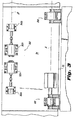
- Optical space telescope 10 includes a primary mirror assembly 12 (shown here in a deployed position), a tower 14 that extends from the center of the primary mirror assembly 12, and a secondary mirror 16 which is mounted atop the central tower 14.
- the primary mirror assembly or optic 12 consists of a hexagonal central hub portion 18 and six petals 20a-20f that are independently hinged to the central hub portion 18.
- each petal 20a-20f has a launch latch strut 22 associated therewith that secures the petal in a stowed position.
- Each petal 20a-20f has a figure-controlled reflective surface 24 that is formed from fused silica facesheets and a housing 26 formed from a light-weight carbon composite material. The shape of the reflective surface 24 of each petal 20a-20f is controlled by a plurality of figure control actuators (not shown) positioned within the petal housing 26.
- each petal housing 26 forms a triangular petal root structure 30 that supports a pair of hinge assemblies 100, 200 which are discussed in greater detail hereinbelow.
- Each of the petals 20a-20f is operatively connected to the central hub portion 18 of primary mirror assembly 12 by two hinge assemblies 100, 200 (see Fig. 4).
- the petal root structure 30 also supports a clevis 50 that forms part of a latch assembly 300 operatively associated with the central hub portion 18 for engaging the clevis 50 upon movement of a petal from the stowed position of Fig. 2 to the deployed position of Fig. 1.
- each paired set of hinges assemblies 100 and 200 define a common hinge line or axis A about which the petal associated therewith rotates, and along which thermal expansion and contraction, as well as rigid movement of the petal structure is accommodated.
- the latch assembly 300 defines a latch line or axis B that is spaced from and parallel to the hinge axis A.
- the latch assembly 300 is adapted and configured to accommodate thermal expansion and contraction, as well as rigid axial movement of the petal structure along latch axis B.
- hinge assembly 100 is a one degree of freedom hinge assembly (1DOF) in that it is adapted and configured to afford the petal associated therewith freedom of rotation about the petal hinge axis.
- Hinge assembly 100 includes a root mount 110 secured to the mounting surface 32 of the root structure 30 of a petal 20, and a hub mount 120 secured a mounting surface 34 of the central hub portion 18 of primary mirror assembly 12.
- the root mount 110 is defined by a base 112 and pair of upstanding trusses 114a and 114b.
- the base 112 is secured to the mounting structure 32 of the petal root structure 30 by a plurality of fasteners 35.
- the trusses 114a and 114b have respective hemi-cylindrical channels 116a and 116b for accommodating an axial hinge shaft 130.
- Channels 116a and 116b are further defined and enclosed by corresponding channeled root mount caps 118a and 118b that are secured to the trusses 114a and 114b, respectively, by fasteners 37.
- Hinge shaft 130 is secured to the root mount 110 of hinge assembly 100 by a pair of axially spaced apart woodruff keys 140a and 140b. More particularly, woodruff keys 140a and 140b are seated in corresponding slots 115a and 115b that are respectively formed in the channels 116a and 116b of trusses 114a and 114b. The two keys 140a and 140b are positioned to engage complementary slots (not shown) that are formed in hinge shaft 130 to secure the orientation of the shaft 130 with respect to the root mount 110.
- Hinge shaft 130 is divided into two sections 130a, 130b separated by an annular collar 132.
- the first shaft portion 130a of hinge shaft 130 extends laterally from hinge assembly 100 and is supported within a stabilizing block 160 is fixedly secured to the mounting surface 34 of hub portion 18, as best seen in Fig. 4.
- the second shaft portion 130b supports four axially spaced apart angular contact bearings 150a-150e which are axially aligned and retained between the annular collar 132 and a retaining collar 128.
- the angular contact bearings 150a-150d are preferably formed from silicon nitride, and do not require lubrication.
- Each angular contact bearing 150a-150d has relatively movable inner and outer races 152 and 154. The inner race 152 of each bearing is tightly fit onto the first shaft portion 130b of hinge shaft 130.
- the hub mount 120 of hinge assembly 100 is defined by a base 122 and a pair of upstanding trusses 124a and 124b.
- the base 122 is secured to the mounting structure 32 of the petal root structure 30 by a plurality of fasteners 35.
- the trusses 124 and 124b transition into a cylindrical housing 126.
- the outer race 154 of each of the angular contact bearings 150a-150d is tightly fit within the cylindrical housing 126 of hub mount 120.
- the four contact bearings are enclosed within the cylindrical housing 126 by a retainer ring 125 that is secured to the end of the housing 126 by plurality of threaded fasteners 137.
- hinge assembly 200 is a two degree-of-freedom hinge assembly (2DOF) in that it adapted and configured to afford the petal associated therewith freedom of rotation about the petal hinge axis, as well as freedom to expand and contract thermally, and move rigidly along the petal hinge axis in a frictionless, unconstrained manner.
- Hinge assembly 200 includes a root mount 210 secured to the mounting surface 32 of the root structure 30 of a petal 20, and a hub mount 220 secured to the mounting surface 34 the central hub portion 18 of the primary mirror assembly 12.
- the root mount 210 is defined by a base 212 and pair of upstanding trusses 214a and 214b.
- the base 112 is secured to the mounting structure 32 of the petal root structure 30 by a plurality of fasteners 35.
- the trusses 214a and 214b have respective hemi-cylindrical channels 216a and 216b for accommodating an axial hinge shaft 230. Channels 216a and 216b are further defined and enclosed by corresponding channeled root mount caps 218a and 218b that are secured to the trusses 214a and 214b, respectively, by fasteners 37.
- Hinge shaft 230 is supported by the root mount 210, and more particularly is seated within the channels formed by trusses 214a, 214b and root mount caps 218a, 218b.
- a unique bearing assembly 250 that enables hinge assembly 200 to provide two degrees of freedom, is operatively associated with hinge shaft 230.
- Bearing assembly 250 includes a cylindrical bearing cage 240 that is preferably formed from PTFE, and retains a plurality of ball bearings 245 formed from silicon nitride. The ball bearings 245 are arranged in a splined pattern.
- Bearing assembly 250 further includes a cylindrical inner bearing race 252 and a cylindrical outer bearing race 254.
- the inner bearing race 252 is intimately engaged with hinge shaft 230, retained by the annular shaft collar 232.
- the outer bearing race 254 is intimately engaged with hub mount 220.
- the hub mount 220 of hinge assembly 100 is defined by a base 222 and a pair of upstanding trusses 224a and 224b.
- the base 222 is secured to the mounting structure 32 of the petal root structure 30 by a plurality of fasteners 35.
- the trusses 224 and 224b transition into a cylindrical housing 226.
- the outer cylindrical race 254 of bearing assembly 250 is accommodated within the cylindrical housing 226 of hub mount 220.
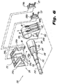
- latch assembly 300 is a double throw latch assembly that is extremely stable in that it exhibits high stiffness and low hysterisis when subjected to operational loads experienced during deployment.
- Latch assembly 300 is adapted and configured to afford the petal associated therewith freedom to expand and contract thermally, and move rigidly along the latch axis B. More specifically, latch assembly 300 is designed to constrain four degrees-of-freedom and allow unconstrained motion relative to the hinge axis A in two degrees-of-freedom. That is, the latch assembly 300 constrains the petal rotational degree-of-freedom about the hinge axis A, as well as the lateral degree-of-freedom and two rotational degrees-of-freedom about the hinge axis A.
- the latch assembly 300 includes the clevis 50 secured to the mounting surface 32 of petal root structure 30 and which defines a reception aperture 52 (see Fig. 4).
- Latch assembly 300 further includes a pair of laterally opposed latches 302a and 302b which are operatively associated with the mounting surface 34 of the central hub portion 18 of primary mirror assembly 12 for engaging the reception aperture 52 of the clevis 50 upon movement of a petal from the stowed position of Fig. 2 to the deployed position of Fig. 1.
- each latch includes a latch shaft 330 mounted for linear movement along latch axis B.
- An actuator 360 disposed within a housing 362 fastened to the mounting surface 34 of central hub portion 18 is coupled to the end of each latch shaft 330 by way of a linkage assembly 380.
- the actuator 360 is adapted and configured to facilitate axial advancement of the latch shaft 330 relative to the reception aperture 52 of clevis 50.
- Linkage assembly 380 includes a fore link 382 fastened to the end of latch shaft 330, a primary medial link 383 and an aft coupling 384 operatively associated with the actuator drive shaft 364.
- Medial link 383 is associated with aft coupling 384 through a biasing member 394, and to fore link 383 through a pivot member 393.
- Each latch shaft 330 is operatively associated with a bearing assembly 350 that includes a cylindrical bearing cage 340 that is formed from PTFE and configured to retain a plurality of ball bearings 345 formed from silicon nitride.
- the ball bearings 345 are seated in respective apertures and are arranged in a spline pattern.
- Each bearing cage 340 is disposed between a cylindrical inner bearing race 352 and a cylindrical outer bearing race 354.
- the inner bearing race 352 is intimately engaged with latch shaft 330, retained in part by annular shaft collar 332.
- the outer bearing race 354 is supported in a hub mount 320.
- Hub mount 320 includes a base 322 having upstanding trusses 324a and 324b fastened to the mounting surface 34 of the central hub portion 18 by a plurality of fasteners 335.
- the trusses 324a, 324b transition into a cylindrical housing 326.
- the outer cylindrical bearing race 354 is accommodated within the cylindrical housing 326 of hub mount 320.
- the relatively movable inner and outer races 352 and 354 of bearing assembly 350 afford rotational and linear movement of the root mount 310 relative to clevis 50 along the axis of the hinge shaft 330 when the petal is in the deployed and latched position. Consequently, thermal expansion and contraction of the petal root structure will be accommodated by the latch assemblies 300, along with rigid movement of the root structure along the hinge axis in a frictionless, unconstrained manner relative to the latch axis B.
- a tapered bearing 375 is mounted to the free end of latch shaft 330 by a support hub 380 and secured by a fastener 382.
- Tapered bearing 375 carries a plurality of cylindrical rollers 385 adapted and configured to engage the reception aperture 52 of clevis 50, as discussed in more detail hereinbelow.
- petals 20a-20f of mirror assembly 12 are independently rotated into the deployed positions shown in Fig. 1, the opposed latches 302a, 302b of latch assembly 300 slide past the clevis 50 without making contact therewith.
- the reception aperture 52 of the clevis 50 on each petal root 30 is aligned with the latch axis B defined by the opposed latch shafts 330a, 330b of latches 302a, 302b, as best seen in Fig. 8.
- the tapered bearings 375a, 375b on the end of latch shafts 330a, 330b are spaced from the clevis 50.
- the respective drive shafts 364a, 364b of actuators 360a, 360b which are coupled to latch shafts 330a, 330b respectively, are actuated, preferably simultaneously. This, in turn, causes the tapered bearings 375a, 375b to translate axially into engagement with the reception bore 52 of clevis 50, as best seen in Fig. 9.
- each latch shaft 330, 330b Upon engagement, the rollers 385 within the tapered bearings 375a, 375b on the end of each latch shaft 330, 330b contact a reception bore liner 54 secured within the reception bore 52 of clevis 50. During this engagement, no latching forces are created in the petal root structure.
- the distance through which the latch shafts 330a, 330b travel to engage the reception bore 52 of the clevis 50 is relatively small compared to their overall length. This ensures that the bearing cage 340 with which each latch shaft 330a, 330b is associated does not become displaced from its housing defined by hub mount 320.
- the mating forces exerted by the opposed latches 302a, 302b on the clevis 50 are equal and opposite, thus ensuring that a moment will not be applied to the clevis 50 during engagement.
- the double throw latch assembly 300 of the subject invention exhibits axial stiffness on the order of 1,000,000 lbs/in. Consequently, when the opposed latches 302a, 302b are engaged, as shown in Fig. 9, the clevis 50 will not rotate and re-seat with the rollers 385 in the bearing 375a, 375b on the end of each latch shaft 330a, 330b.
- a system for deploying the petals of a sectored mirror assembly of an optical space telescope, wherein the sectored mirror includes a central hub and a plurality of petals disposed about the periphery of the central hub, and each petal has a petal root independently hinged to the central hub.
- the system includes a first hinge assembly having a root mount secured to a petal root and a hub mount secured the central hub, whereby the first hinge assembly affords the petal associated therewith freedom of rotation about a petal hinge axis.
- the system further includes a second hinge assembly including a root mount secured to the petal root and a hub mount secured to the central hub, whereby the second hinge assembly affords the petal associated therewith freedom of rotation about the petal hinge axis and freedom to expand and contract thermally, and move rigidly along the petal hinge axis in a frictionless, unconstrained manner.
- the system also includes a latch assembly including a clevis secured to the petal root at a location spaced from the hinge axis and a pair of laterally opposed latch mechanism operatively associated with the central hub for engaging the clevis upon rotation of the petal about the hinge axis from a stowed position to a deployed position.
Landscapes
- Engineering & Computer Science (AREA)
- General Engineering & Computer Science (AREA)
- Mechanical Engineering (AREA)
- Remote Sensing (AREA)
- Aviation & Aerospace Engineering (AREA)
- Physics & Mathematics (AREA)
- Sustainable Development (AREA)
- Astronomy & Astrophysics (AREA)
- Life Sciences & Earth Sciences (AREA)
- General Physics & Mathematics (AREA)
- Optics & Photonics (AREA)
- Telescopes (AREA)
- Rolling Contact Bearings (AREA)
- Mounting And Adjusting Of Optical Elements (AREA)
- Pivots And Pivotal Connections (AREA)
- Lenses (AREA)
Priority Applications (1)
| Application Number | Priority Date | Filing Date | Title |
|---|---|---|---|
| EP07011070A EP1835321B1 (de) | 2002-08-09 | 2003-08-08 | Optischen Weltraumteleskop mit einem Verriegelungssystem zum Feststellen der Spiegelsegmente |
Applications Claiming Priority (3)
| Application Number | Priority Date | Filing Date | Title |
|---|---|---|---|
| US216255 | 2002-08-09 | ||
| US10/216,255 US6768582B1 (en) | 2002-08-09 | 2002-08-09 | System for deploying the petals of a sectored mirror of an optical space telescope |
| EP03018138A EP1391766B1 (de) | 2002-08-09 | 2003-08-08 | Mechanismus zur Entfaltung der Segmente eines optischen Weltraumteleskops |
Related Parent Applications (2)
| Application Number | Title | Priority Date | Filing Date |
|---|---|---|---|
| EP03018138A Division EP1391766B1 (de) | 2002-08-09 | 2003-08-08 | Mechanismus zur Entfaltung der Segmente eines optischen Weltraumteleskops |
| EP03018138.2 Division | 2003-08-08 |
Related Child Applications (1)
| Application Number | Title | Priority Date | Filing Date |
|---|---|---|---|
| EP07011070A Division EP1835321B1 (de) | 2002-08-09 | 2003-08-08 | Optischen Weltraumteleskop mit einem Verriegelungssystem zum Feststellen der Spiegelsegmente |
Publications (2)
| Publication Number | Publication Date |
|---|---|
| EP1566678A1 true EP1566678A1 (de) | 2005-08-24 |
| EP1566678B1 EP1566678B1 (de) | 2008-01-09 |
Family
ID=31187910
Family Applications (4)
| Application Number | Title | Priority Date | Filing Date |
|---|---|---|---|
| EP07011070A Expired - Lifetime EP1835321B1 (de) | 2002-08-09 | 2003-08-08 | Optischen Weltraumteleskop mit einem Verriegelungssystem zum Feststellen der Spiegelsegmente |
| EP05010788A Expired - Lifetime EP1566679B1 (de) | 2002-08-09 | 2003-08-08 | Gelenk zur Entfaltung der Segmente eines optischen Weltraumteleskops |
| EP03018138A Expired - Lifetime EP1391766B1 (de) | 2002-08-09 | 2003-08-08 | Mechanismus zur Entfaltung der Segmente eines optischen Weltraumteleskops |
| EP05010787A Expired - Lifetime EP1566678B1 (de) | 2002-08-09 | 2003-08-08 | Riegel zur Fixierung des Segments eines optischen Weltraumteleskops |
Family Applications Before (3)
| Application Number | Title | Priority Date | Filing Date |
|---|---|---|---|
| EP07011070A Expired - Lifetime EP1835321B1 (de) | 2002-08-09 | 2003-08-08 | Optischen Weltraumteleskop mit einem Verriegelungssystem zum Feststellen der Spiegelsegmente |
| EP05010788A Expired - Lifetime EP1566679B1 (de) | 2002-08-09 | 2003-08-08 | Gelenk zur Entfaltung der Segmente eines optischen Weltraumteleskops |
| EP03018138A Expired - Lifetime EP1391766B1 (de) | 2002-08-09 | 2003-08-08 | Mechanismus zur Entfaltung der Segmente eines optischen Weltraumteleskops |
Country Status (5)
| Country | Link |
|---|---|
| US (4) | US6768582B1 (de) |
| EP (4) | EP1835321B1 (de) |
| JP (3) | JP4047781B2 (de) |
| AT (4) | ATE360834T1 (de) |
| DE (5) | DE60325661D1 (de) |
Families Citing this family (33)
| Publication number | Priority date | Publication date | Assignee | Title |
|---|---|---|---|---|
| USD615071S1 (en) * | 2003-09-09 | 2010-05-04 | Qinetiq Limited | Deployable sensor module |
| GB0321041D0 (en) * | 2003-09-09 | 2004-02-04 | Qinetiq Ltd | Sensor apparatus and system |
| FR2890454B1 (fr) * | 2005-09-05 | 2007-10-12 | Alcatel Sa | Reflecteur deployable en forme de triangle de reuleaux, pour un instrument d'observation spatiale |
| US7913953B2 (en) * | 2005-12-28 | 2011-03-29 | Frank Werner Ellinghaus | Solar sail launch system and solar sail attitude control system |
| US7782530B1 (en) * | 2006-06-26 | 2010-08-24 | Sandia Corporation | Deployable telescope having a thin-film mirror and metering structure |
| FR2902765B1 (fr) * | 2006-06-27 | 2008-08-29 | Alcatel Sa | Dispositif de positionnement en rotation a grande duree de vie pour applications spatiales |
| FR2902764B1 (fr) * | 2006-06-27 | 2009-09-25 | Alcatel Sa | Structure deployable comportant des elements rigides, embarquee sur un engin spatial |
| FR2903387B1 (fr) * | 2006-07-05 | 2008-08-29 | Alcatel Sa | Actionneur pour systemes de guidage d'equipements spatiaux a taux de rotation variable |
| FR2905804B1 (fr) * | 2006-09-13 | 2010-10-22 | Cit Alcatel | Instrument d'acquisition spatiale a reflecteur(s) deployable(s) et a compacite elevee |
| JP5276952B2 (ja) * | 2008-11-05 | 2013-08-28 | サカセ・アドテック株式会社 | 伸展構造物 |
| US8947777B2 (en) | 2011-02-25 | 2015-02-03 | Utah State University Research Foundation | Multiple petal deployable telescope |
| US9366853B2 (en) | 2011-02-25 | 2016-06-14 | Utah State University Research Foundation | Multiple petal deployable telescope |
| FR2974787B1 (fr) * | 2011-05-05 | 2014-11-28 | Thales Sa | Dispositif de protection d'un instrument optique multifaisceaux |
| US9004409B1 (en) * | 2011-08-23 | 2015-04-14 | Space Systems/Loral, Llc | Extendable antenna reflector deployment techniques |
| US9248922B1 (en) * | 2011-08-23 | 2016-02-02 | Space Systems/Loral, Llc | Reflector deployment techniques for satellites |
| US9331394B2 (en) | 2011-09-21 | 2016-05-03 | Harris Corporation | Reflector systems having stowable rigid panels |
| US20130201571A1 (en) | 2012-02-03 | 2013-08-08 | Raytheon Company | Hinge mechanism for small optics and related methods |
| US9423608B2 (en) | 2012-08-01 | 2016-08-23 | Pentair Water Pool And Spa, Inc. | Multidimensional rotary motion apparatus moving a reflective surface and method of operating same |
| US9134599B2 (en) | 2012-08-01 | 2015-09-15 | Pentair Water Pool And Spa, Inc. | Underwater image projection controller with boundary setting and image correction modules and interface and method of using same |
| FR3023011B1 (fr) * | 2014-06-27 | 2017-10-20 | Thales Sa | Procede de fabrication d'un miroir |
| CN104765122B (zh) * | 2015-04-29 | 2017-01-18 | 哈尔滨工业大学 | 空间可伸缩桁架式二元光学相机及其在轨工作方法 |
| USD843635S1 (en) * | 2015-11-12 | 2019-03-19 | Antoinetta Jacoba Hendrika Van Egmond | Solar powered lamp |
| US10683107B2 (en) * | 2017-08-04 | 2020-06-16 | The Aerospace Corporation | Release apparatus and methods of assembling same |
| US10811759B2 (en) | 2018-11-13 | 2020-10-20 | Eagle Technology, Llc | Mesh antenna reflector with deployable perimeter |
| US11139549B2 (en) | 2019-01-16 | 2021-10-05 | Eagle Technology, Llc | Compact storable extendible member reflector |
| US10797400B1 (en) | 2019-03-14 | 2020-10-06 | Eagle Technology, Llc | High compaction ratio reflector antenna with offset optics |
| CN110703408B (zh) * | 2019-11-30 | 2022-05-31 | 中国人民解放军战略支援部队航天工程大学 | 一种主次镜伸缩系统 |
| CN111610738B (zh) * | 2020-05-26 | 2021-06-01 | 清华大学深圳国际研究生院 | 一种空间望远镜展开机构、控制系统和方法 |
| US12043416B2 (en) | 2020-11-26 | 2024-07-23 | Wyvern Incorporated | Satellite with deployable optical assembly |
| CN115508997B (zh) * | 2022-06-22 | 2024-08-06 | 中国科学院微小卫星创新研究院 | 一种超大口径太空望远镜及其展开方式 |
| KR102697245B1 (ko) * | 2023-11-14 | 2024-08-22 | 대한민국(방위사업청장) | 전자 광학 탑재체 |
| KR102697241B1 (ko) * | 2023-11-14 | 2024-08-23 | 대한민국(방위사업청장) | 전자 광학 탑재체용 광학모듈 및 이를 구비하는 전자 광학 탑재체 |
| KR102697244B1 (ko) * | 2023-11-14 | 2024-08-23 | 대한민국(방위사업청장) | 전자 광학 탑재체용 광학모듈 및 이를 구비하는 전자 광학 탑재체 |
Citations (3)
| Publication number | Priority date | Publication date | Assignee | Title |
|---|---|---|---|---|
| US3433436A (en) * | 1967-03-20 | 1969-03-18 | Us Navy | Ball release mechanism |
| US4753465A (en) * | 1986-04-11 | 1988-06-28 | James F. Dalby | Remotely operable locking mechanism |
| US4997218A (en) * | 1990-01-22 | 1991-03-05 | The United States Of America As Represented By The Secretary Of The Army | Pin lock mechanism with bias change feature |
Family Cites Families (20)
| Publication number | Priority date | Publication date | Assignee | Title |
|---|---|---|---|---|
| US3043634A (en) * | 1960-08-11 | 1962-07-10 | Coley Samuel Ernest | Bearings |
| US3446540A (en) * | 1966-10-12 | 1969-05-27 | Ted Geffner | Anti-friction bearings |
| FR1524355A (fr) * | 1967-03-31 | 1968-05-10 | Sud Aviation | Dispositif d'articulation adapté aux éléments de déploiement d'engins spatiaux |
| US3469894A (en) * | 1967-10-12 | 1969-09-30 | Superior Die Set Corp | Die set leader pin with sectional bearing cage |
| US3635425A (en) * | 1969-10-01 | 1972-01-18 | Us Navy | Deployment method for a telescoping solar array |
| CH654886A5 (de) * | 1981-11-03 | 1986-03-14 | Schmid Sro Kugellager | Kugelbuechse fuer unbegrenzte laengsbewegungen. |
| JP2914804B2 (ja) * | 1991-11-20 | 1999-07-05 | 日本トムソン株式会社 | ストロークベアリング |
| US5290107A (en) * | 1992-09-24 | 1994-03-01 | Hanaway Ronald L | Guide post, guide sleeve and improved air impulse rotary ball cage assembly |
| DE4337968C2 (de) * | 1992-11-10 | 1994-09-08 | Deutsche Aerospace | Gelenk zum Entfalten und Verriegeln von Raumfahrtelementen |
| US5451975A (en) | 1993-02-17 | 1995-09-19 | Space Systems/Loral, Inc. | Furlable solid surface reflector |
| US5600868A (en) * | 1995-03-07 | 1997-02-11 | Santa Barbara Research Center | Deployment hinge |
| US5785280A (en) * | 1995-07-20 | 1998-07-28 | Space Systems/Loral, Inc. | Hybrid solar panel array |
| DE19649741C2 (de) * | 1996-11-30 | 1999-07-15 | Daimler Benz Aerospace Ag | Gelenk zum Entfalten und Verriegeln einer Solarpaneele oder eines Reflektors |
| US5898529A (en) | 1997-06-20 | 1999-04-27 | Ball Aerospace & Technologies, Inc. | Deployable space-based telescope |
| GB9803918D0 (en) * | 1997-07-05 | 1998-04-22 | Matra Marconi Space Uk Ltd | Spacecraft platforms |
| US6047928A (en) | 1998-05-19 | 2000-04-11 | Hughes Electronics Corporation | Friction clamp restraint mechanism for springback reflectors |
| US6175989B1 (en) | 1998-05-26 | 2001-01-23 | Lockheed Corp | Shape memory alloy controllable hinge apparatus |
| US6191757B1 (en) | 1999-04-08 | 2001-02-20 | Hughes Electronics Corporation | System for compact stowage of segmented dish reflectors |
| US6505381B1 (en) * | 1999-07-30 | 2003-01-14 | Trw Astro Aerospace | Pulley actuated translational hinge system |
| US6767155B2 (en) * | 2002-04-05 | 2004-07-27 | Eastman Kodak Company | High stability latch mechanism |
-
2002
- 2002-08-09 US US10/216,255 patent/US6768582B1/en not_active Expired - Fee Related
-
2003
- 2003-08-08 DE DE60325661T patent/DE60325661D1/de not_active Expired - Lifetime
- 2003-08-08 EP EP07011070A patent/EP1835321B1/de not_active Expired - Lifetime
- 2003-08-08 JP JP2003290228A patent/JP4047781B2/ja not_active Expired - Fee Related
- 2003-08-08 EP EP05010788A patent/EP1566679B1/de not_active Expired - Lifetime
- 2003-08-08 AT AT05010788T patent/ATE360834T1/de not_active IP Right Cessation
- 2003-08-08 DE DE20321565U patent/DE20321565U1/de not_active Expired - Lifetime
- 2003-08-08 EP EP03018138A patent/EP1391766B1/de not_active Expired - Lifetime
- 2003-08-08 AT AT05010787T patent/ATE383590T1/de not_active IP Right Cessation
- 2003-08-08 DE DE60318614T patent/DE60318614T2/de not_active Expired - Lifetime
- 2003-08-08 AT AT07011070T patent/ATE419552T1/de not_active IP Right Cessation
- 2003-08-08 DE DE60306047T patent/DE60306047D1/de not_active Expired - Lifetime
- 2003-08-08 EP EP05010787A patent/EP1566678B1/de not_active Expired - Lifetime
- 2003-08-08 DE DE60313488T patent/DE60313488T2/de not_active Expired - Lifetime
- 2003-08-08 AT AT03018138T patent/ATE330243T1/de not_active IP Right Cessation
-
2004
- 2004-06-16 US US10/869,517 patent/US6972901B2/en not_active Expired - Fee Related
- 2004-06-16 US US10/869,072 patent/US6863408B2/en not_active Expired - Fee Related
- 2004-11-16 US US10/990,240 patent/US6956696B2/en not_active Expired - Fee Related
-
2007
- 2007-08-13 JP JP2007211000A patent/JP4782081B2/ja not_active Expired - Fee Related
- 2007-08-13 JP JP2007210998A patent/JP4677430B2/ja not_active Expired - Fee Related
Patent Citations (3)
| Publication number | Priority date | Publication date | Assignee | Title |
|---|---|---|---|---|
| US3433436A (en) * | 1967-03-20 | 1969-03-18 | Us Navy | Ball release mechanism |
| US4753465A (en) * | 1986-04-11 | 1988-06-28 | James F. Dalby | Remotely operable locking mechanism |
| US4997218A (en) * | 1990-01-22 | 1991-03-05 | The United States Of America As Represented By The Secretary Of The Army | Pin lock mechanism with bias change feature |
Also Published As
Similar Documents
| Publication | Publication Date | Title |
|---|---|---|
| EP1566679B1 (de) | Gelenk zur Entfaltung der Segmente eines optischen Weltraumteleskops | |
| JP6835966B2 (ja) | 圧力容器の壁を介して操作可能である、ロック可能な精密アジャスタスクリュー | |
| KR102127082B1 (ko) | 안테나 위치 설정 메커니즘 | |
| US7188831B2 (en) | Flexure-type suspension system providing for three degrees of freedom and flexure-type positioning assembly based thereon | |
| AU2021276587B2 (en) | Device for deploying and pointing an item of equipment carried by a spacecraft | |
| US7275285B1 (en) | Deployment hinge | |
| US5853260A (en) | Rotation center type joint and assemblies using it | |
| US4806027A (en) | Apparatus for strain-free mounting of optical components | |
| Hachkowski et al. | Riegel zur Fixierung des Segments eines optischen Weltraumteleskops Verrou pour la fixation d’un miroir segmenté d’un télescope spatial | |
| Wiitala et al. | A more flexible robotic wrist |
Legal Events
| Date | Code | Title | Description |
|---|---|---|---|
| PUAI | Public reference made under article 153(3) epc to a published international application that has entered the european phase |
Free format text: ORIGINAL CODE: 0009012 |
|
| 17P | Request for examination filed |
Effective date: 20050518 |
|
| AC | Divisional application: reference to earlier application |
Ref document number: 1391766 Country of ref document: EP Kind code of ref document: P |
|
| AK | Designated contracting states |
Kind code of ref document: A1 Designated state(s): AT BE BG CH CY CZ DE DK EE ES FI FR GB GR HU IE IT LI LU MC NL PT RO SE SI SK TR |
|
| AKX | Designation fees paid |
Designated state(s): AT BE BG CH CY CZ DE DK EE ES FI FR GB GR HU IE IT LI LU MC NL PT RO SE SI SK TR |
|
| 17Q | First examination report despatched |
Effective date: 20060317 |
|
| 17Q | First examination report despatched |
Effective date: 20060317 |
|
| GRAP | Despatch of communication of intention to grant a patent |
Free format text: ORIGINAL CODE: EPIDOSNIGR1 |
|
| GRAS | Grant fee paid |
Free format text: ORIGINAL CODE: EPIDOSNIGR3 |
|
| GRAA | (expected) grant |
Free format text: ORIGINAL CODE: 0009210 |
|
| AC | Divisional application: reference to earlier application |
Ref document number: 1391766 Country of ref document: EP Kind code of ref document: P |
|
| AK | Designated contracting states |
Kind code of ref document: B1 Designated state(s): AT BE BG CH CY CZ DE DK EE ES FI FR GB GR HU IE IT LI LU MC NL PT RO SE SI SK TR |
|
| RAP1 | Party data changed (applicant data changed or rights of an application transferred) |
Owner name: GOODRICH CORPORATION |
|
| REG | Reference to a national code |
Ref country code: GB Ref legal event code: FG4D |
|
| REG | Reference to a national code |
Ref country code: CH Ref legal event code: EP |
|
| REG | Reference to a national code |
Ref country code: IE Ref legal event code: FG4D |
|
| REG | Reference to a national code |
Ref country code: CH Ref legal event code: NV Representative=s name: A. BRAUN, BRAUN, HERITIER, ESCHMANN AG PATENTANWAE |
|
| REF | Corresponds to: |
Ref document number: 60318614 Country of ref document: DE Date of ref document: 20080221 Kind code of ref document: P |
|
| PG25 | Lapsed in a contracting state [announced via postgrant information from national office to epo] |
Ref country code: SI Free format text: LAPSE BECAUSE OF FAILURE TO SUBMIT A TRANSLATION OF THE DESCRIPTION OR TO PAY THE FEE WITHIN THE PRESCRIBED TIME-LIMIT Effective date: 20080109 Ref country code: NL Free format text: LAPSE BECAUSE OF FAILURE TO SUBMIT A TRANSLATION OF THE DESCRIPTION OR TO PAY THE FEE WITHIN THE PRESCRIBED TIME-LIMIT Effective date: 20080109 |
|
| REG | Reference to a national code |
Ref country code: CH Ref legal event code: PFA Owner name: GOODRICH CORPORATION Free format text: GOODRICH CORPORATION#FOUR COLISEUM CENTRE 2730 WEST TYVOLA ROAD#CHARLOTTE, NC 28217-4578 (US) -TRANSFER TO- GOODRICH CORPORATION#FOUR COLISEUM CENTRE 2730 WEST TYVOLA ROAD#CHARLOTTE, NC 28217-4578 (US) |
|
| NLV1 | Nl: lapsed or annulled due to failure to fulfill the requirements of art. 29p and 29m of the patents act | ||
| PG25 | Lapsed in a contracting state [announced via postgrant information from national office to epo] |
Ref country code: ES Free format text: LAPSE BECAUSE OF FAILURE TO SUBMIT A TRANSLATION OF THE DESCRIPTION OR TO PAY THE FEE WITHIN THE PRESCRIBED TIME-LIMIT Effective date: 20080420 Ref country code: FI Free format text: LAPSE BECAUSE OF FAILURE TO SUBMIT A TRANSLATION OF THE DESCRIPTION OR TO PAY THE FEE WITHIN THE PRESCRIBED TIME-LIMIT Effective date: 20080109 |
|
| ET | Fr: translation filed | ||
| PG25 | Lapsed in a contracting state [announced via postgrant information from national office to epo] |
Ref country code: AT Free format text: LAPSE BECAUSE OF FAILURE TO SUBMIT A TRANSLATION OF THE DESCRIPTION OR TO PAY THE FEE WITHIN THE PRESCRIBED TIME-LIMIT Effective date: 20080109 Ref country code: BG Free format text: LAPSE BECAUSE OF FAILURE TO SUBMIT A TRANSLATION OF THE DESCRIPTION OR TO PAY THE FEE WITHIN THE PRESCRIBED TIME-LIMIT Effective date: 20080409 |
|
| PG25 | Lapsed in a contracting state [announced via postgrant information from national office to epo] |
Ref country code: BE Free format text: LAPSE BECAUSE OF FAILURE TO SUBMIT A TRANSLATION OF THE DESCRIPTION OR TO PAY THE FEE WITHIN THE PRESCRIBED TIME-LIMIT Effective date: 20080109 Ref country code: PT Free format text: LAPSE BECAUSE OF FAILURE TO SUBMIT A TRANSLATION OF THE DESCRIPTION OR TO PAY THE FEE WITHIN THE PRESCRIBED TIME-LIMIT Effective date: 20080609 |
|
| PG25 | Lapsed in a contracting state [announced via postgrant information from national office to epo] |
Ref country code: SE Free format text: LAPSE BECAUSE OF FAILURE TO SUBMIT A TRANSLATION OF THE DESCRIPTION OR TO PAY THE FEE WITHIN THE PRESCRIBED TIME-LIMIT Effective date: 20080409 Ref country code: DK Free format text: LAPSE BECAUSE OF FAILURE TO SUBMIT A TRANSLATION OF THE DESCRIPTION OR TO PAY THE FEE WITHIN THE PRESCRIBED TIME-LIMIT Effective date: 20080109 Ref country code: CZ Free format text: LAPSE BECAUSE OF FAILURE TO SUBMIT A TRANSLATION OF THE DESCRIPTION OR TO PAY THE FEE WITHIN THE PRESCRIBED TIME-LIMIT Effective date: 20080109 Ref country code: SK Free format text: LAPSE BECAUSE OF FAILURE TO SUBMIT A TRANSLATION OF THE DESCRIPTION OR TO PAY THE FEE WITHIN THE PRESCRIBED TIME-LIMIT Effective date: 20080109 |
|
| PLBE | No opposition filed within time limit |
Free format text: ORIGINAL CODE: 0009261 |
|
| STAA | Information on the status of an ep patent application or granted ep patent |
Free format text: STATUS: NO OPPOSITION FILED WITHIN TIME LIMIT |
|
| PG25 | Lapsed in a contracting state [announced via postgrant information from national office to epo] |
Ref country code: RO Free format text: LAPSE BECAUSE OF FAILURE TO SUBMIT A TRANSLATION OF THE DESCRIPTION OR TO PAY THE FEE WITHIN THE PRESCRIBED TIME-LIMIT Effective date: 20080109 |
|
| 26N | No opposition filed |
Effective date: 20081010 |
|
| PG25 | Lapsed in a contracting state [announced via postgrant information from national office to epo] |
Ref country code: MC Free format text: LAPSE BECAUSE OF NON-PAYMENT OF DUE FEES Effective date: 20080831 |
|
| PG25 | Lapsed in a contracting state [announced via postgrant information from national office to epo] |
Ref country code: EE Free format text: LAPSE BECAUSE OF FAILURE TO SUBMIT A TRANSLATION OF THE DESCRIPTION OR TO PAY THE FEE WITHIN THE PRESCRIBED TIME-LIMIT Effective date: 20080109 |
|
| PG25 | Lapsed in a contracting state [announced via postgrant information from national office to epo] |
Ref country code: IE Free format text: LAPSE BECAUSE OF NON-PAYMENT OF DUE FEES Effective date: 20080808 Ref country code: CY Free format text: LAPSE BECAUSE OF FAILURE TO SUBMIT A TRANSLATION OF THE DESCRIPTION OR TO PAY THE FEE WITHIN THE PRESCRIBED TIME-LIMIT Effective date: 20080109 |
|
| PG25 | Lapsed in a contracting state [announced via postgrant information from national office to epo] |
Ref country code: LU Free format text: LAPSE BECAUSE OF NON-PAYMENT OF DUE FEES Effective date: 20080808 Ref country code: HU Free format text: LAPSE BECAUSE OF FAILURE TO SUBMIT A TRANSLATION OF THE DESCRIPTION OR TO PAY THE FEE WITHIN THE PRESCRIBED TIME-LIMIT Effective date: 20080710 |
|
| PG25 | Lapsed in a contracting state [announced via postgrant information from national office to epo] |
Ref country code: TR Free format text: LAPSE BECAUSE OF FAILURE TO SUBMIT A TRANSLATION OF THE DESCRIPTION OR TO PAY THE FEE WITHIN THE PRESCRIBED TIME-LIMIT Effective date: 20080109 |
|
| PG25 | Lapsed in a contracting state [announced via postgrant information from national office to epo] |
Ref country code: GR Free format text: LAPSE BECAUSE OF FAILURE TO SUBMIT A TRANSLATION OF THE DESCRIPTION OR TO PAY THE FEE WITHIN THE PRESCRIBED TIME-LIMIT Effective date: 20080410 |
|
| PGFP | Annual fee paid to national office [announced via postgrant information from national office to epo] |
Ref country code: CH Payment date: 20130813 Year of fee payment: 11 Ref country code: DE Payment date: 20130731 Year of fee payment: 11 |
|
| PGFP | Annual fee paid to national office [announced via postgrant information from national office to epo] |
Ref country code: GB Payment date: 20130807 Year of fee payment: 11 Ref country code: FR Payment date: 20130808 Year of fee payment: 11 |
|
| PGFP | Annual fee paid to national office [announced via postgrant information from national office to epo] |
Ref country code: IT Payment date: 20130821 Year of fee payment: 11 |
|
| REG | Reference to a national code |
Ref country code: CH Ref legal event code: PCAR Free format text: NEW ADDRESS: HOLBEINSTRASSE 36-38, 4051 BASEL (CH) |
|
| REG | Reference to a national code |
Ref country code: DE Ref legal event code: R119 Ref document number: 60318614 Country of ref document: DE |
|
| REG | Reference to a national code |
Ref country code: CH Ref legal event code: PL |
|
| GBPC | Gb: european patent ceased through non-payment of renewal fee |
Effective date: 20140808 |
|
| PG25 | Lapsed in a contracting state [announced via postgrant information from national office to epo] |
Ref country code: IT Free format text: LAPSE BECAUSE OF NON-PAYMENT OF DUE FEES Effective date: 20140808 Ref country code: CH Free format text: LAPSE BECAUSE OF NON-PAYMENT OF DUE FEES Effective date: 20140831 Ref country code: LI Free format text: LAPSE BECAUSE OF NON-PAYMENT OF DUE FEES Effective date: 20140831 |
|
| REG | Reference to a national code |
Ref country code: FR Ref legal event code: ST Effective date: 20150430 |
|
| REG | Reference to a national code |
Ref country code: DE Ref legal event code: R119 Ref document number: 60318614 Country of ref document: DE Effective date: 20150303 |
|
| PG25 | Lapsed in a contracting state [announced via postgrant information from national office to epo] |
Ref country code: DE Free format text: LAPSE BECAUSE OF NON-PAYMENT OF DUE FEES Effective date: 20150303 Ref country code: GB Free format text: LAPSE BECAUSE OF NON-PAYMENT OF DUE FEES Effective date: 20140808 |
|
| PG25 | Lapsed in a contracting state [announced via postgrant information from national office to epo] |
Ref country code: FR Free format text: LAPSE BECAUSE OF NON-PAYMENT OF DUE FEES Effective date: 20140901 |