EP1566567A1 - Metallic belt for stepless speed changer - Google Patents
Metallic belt for stepless speed changer Download PDFInfo
- Publication number
- EP1566567A1 EP1566567A1 EP03772789A EP03772789A EP1566567A1 EP 1566567 A1 EP1566567 A1 EP 1566567A1 EP 03772789 A EP03772789 A EP 03772789A EP 03772789 A EP03772789 A EP 03772789A EP 1566567 A1 EP1566567 A1 EP 1566567A1
- Authority
- EP
- European Patent Office
- Prior art keywords
- metal
- metal ring
- ring assembly
- pulley
- curvature
- Prior art date
- Legal status (The legal status is an assumption and is not a legal conclusion. Google has not performed a legal analysis and makes no representation as to the accuracy of the status listed.)
- Granted
Links
Images


Classifications
-
- F—MECHANICAL ENGINEERING; LIGHTING; HEATING; WEAPONS; BLASTING
- F16—ENGINEERING ELEMENTS AND UNITS; GENERAL MEASURES FOR PRODUCING AND MAINTAINING EFFECTIVE FUNCTIONING OF MACHINES OR INSTALLATIONS; THERMAL INSULATION IN GENERAL
- F16G—BELTS, CABLES, OR ROPES, PREDOMINANTLY USED FOR DRIVING PURPOSES; CHAINS; FITTINGS PREDOMINANTLY USED THEREFOR
- F16G5/00—V-belts, i.e. belts of tapered cross-section
- F16G5/16—V-belts, i.e. belts of tapered cross-section consisting of several parts
Definitions
- the present invention relates to a metal belt for a continuously variable transmission, which comprises a metal ring assembly comprising a plurality of endless metal rings laminated one on another, and a large number of metal elements each having a saddle face formed by crowning in a ring slot into which the metal ring assembly is fitted, the metal belt being wound around a driving pulley and a driven pulley to transmit a driving force.
- a peak point of the crowning is offset outwards (toward a pulley V-face) relative to a widthwise central portion of the saddle face of the metal element, and an inner end of the metal ring assembly is prevented from interfering with a neck of the metal element, resulting in a degradation in durability.
- a decrease in maximum tensile stress on an outer peripheral surface of the metal ring is provided by defining a ratio R2/R1 of a radius R2 of curvature of the metal ring assembly to a radius R1 of curvature of the saddle face of the metal element in a predetermined range.
- Patent Document 3 Patent Document 3
- the metal ring assembly is centered by only the crowning of the saddle face and hence, it is difficult to sufficiently stabilize the widthwise behavior of the metal ring assembly. If the metal ring assembly is moved in a widthwise direction for any reason, there is a possibility that the metal ring assembly may interfere with the neck of the metal element, resulting in a degradation in durability. In addition, the offset amount is not limited and hence, it is feared that the end of the metal ring assembly closer to the pulley V-face may be worn due to the very strong interference with the pulley V-face .
- a point to which attention is paid for defining the radius of curvature of the saddle face and the radius of curvature of the metal ring assembly is a maximum tensile stress on an outer peripheral surface of the metal ring.
- the tensile stress on and the radius of curvature of the metal ring assembly which are conditions for determining a suitable region by an experiment, are appropriate values, respectively, and moreover, the fracture of the metal ring assembly occurs from the side of the inner peripheral surface in most cases.
- the present invention has been accomplished with the above-described circumstances in view, and it is an object of the present invention to prevent the widthwise inner end of the metal ring assembly from being brought into contact with the neck of the metal element to result in a degradation in durability.
- a metal belt for a continuously variable transmission which comprises a metal ring assembly comprising a plurality of endless metal rings laminated one on another, and a large number of metal elements each having a saddle face formed by crowning in a ring slot into which the metal ring assembly is fitted, the metal belt being wound around a driving pulley and a driven pulley to transmit a driving force, characterized in that the position of a peak point of the crowning is offset outwards in a widthwise direction from a widthwise central position on the saddle face, whereby a widthwise outer end of the metal ring assembly is put into abutment against a pulley V-face.
- the widthwise outer end of the metal ring assembly is put into abutment against the pulley V-face by offsetting the position of the peak point of the crowning of the saddle face of the metal element outwards in the widthwise direction from the widthwise central position on the saddle face. Therefore, it is possible to position the metal ring assembly in the widthwise direction by the pulley V-face to stabilize the behavior thereof, and it is possible to prevent the widthwise inner end of the metal ring assembly from being brought into contact with a neck of the metal element.
- the pulley V-face is smooth as compared with the neck of the metal element, leading to inexistence of a difference in level and hence, it is possible to enhance the durability of the metal ring assembly.
- the position of the peak point of the crowning is offset outwards in the widthwise direction, the surface pressure and the stress on the metal ring assembly cannot be increased to exert an adverse influence to the durability of the metal ring assembly.
- the offset amount is equal to or smaller than half of a value provided by the subtraction of a width of the saddle face from a width of the metal ring assembly.
- the offset amount is set at the value equal to or smaller than half of the value provided by the subtraction of the width of the saddle face from the width of the metal ring assembly. Therefore, it is possible not only to reliably prevent the wear of the end of the metal ring assembly, but also to decrease the stress of contact with the pulley V-face and further to ensure the durability of the metal ring assembly.
- a ratio of a radius of curvature of the crowning of the saddle face of the metal element to a radius of curvature of the crowing of the metal ring assembly in a free state is set in accordance with a load applied to the metal ring assembly.
- the ratio of the radii of curvature of the saddle face of the metal element and the metal ring assembly is set in accordance with the load applied to the metal ring assembly and hence, it is possible to alleviate the load on an inner peripheral surface of the innermost metal ring of the metal ring assembly, which is liable to be most a point of starting of fracture, thereby further enhancing the durability.
- the value of the ratio is in a range of 0.5 to 1.0 at an offset amount at which amounts of overhanging of the metal ring assembly from opposite ends of the saddle face during operation are equal to each other.
- the value of the ratio is in the range of 0.5 to 1.0 at the offset amount at which amounts of overhanging of the metal ring assembly from the opposite ends of the saddle face during operation are equal to each other and hence, it is possible to reliably prevent the fracture due to the wearing of the inner peripheral surface of the innermost metal ring.
- Figs.1 to 12 show an embodiment of the present invention.
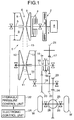
- Fig.1 is a skeleton diagram of a power-transmitting system in a vehicle having a continuously variable transmission mounted therein;
- Fig. 2 is a partially perspective view of a metal belt;
- Fig.3 is a front view of a metal element;
- Fig. 4 is a graph showing the relationship between the distance between an inner end of a metal ring assembly and a neck of the metal element and the offset amount;
- Fig.1 is a skeleton diagram of a power
- Fig. 5 is a graph showing the relationship between the maximum surface pressure on an innermost metal ring and the offset amount;
- Fig.6 is a graph showing the maximum surface pressures on the innermost metal ring, corresponding to various offset amounts;
- Fig.7 is a graph showing the maximum stresses on the metal ring, corresponding to various offset amounts;
- Fig. 8 is a graph showing a distribution of widthwise surface pressures on an inner surface of the metal ring, when radius of curvature of a saddle face was varied; Fig.
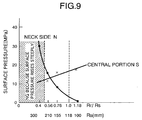
- Fig. 9 is a graph showing a variation in surface pressure on the inner surface of the metal ring with respect to the ratio Rr/Rs of a radius of curvature of the metal ring assembly to a radius of curvature of the saddle face;
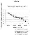
- Fig.10 is a graph showing a variation in stress amplitude on the innermost metal ring with respect to the radius of curvature of the saddle face;
- Fig.11 is a graph showing a variation in stress amplitude on the innermost metal ring with respect to the ratio Rr/Rs of the radius of curvature of the metal ring assembly to the radius of curvature of the saddle face;
- Fig.12 is a graph showing suitable regions of the ratio Rr/Rs of the radius of curvature of the metal ring assembly to the radius of curvature of the saddle face and the offset amount.
- Figs.1 to 12 show an embodiment of the present invention.
- the definition of forward and backward directions, leftward and rightward directions and radial directions of a metal element used in the embodiment is shown in Fig.2.
- the radial directions are defined as radial directions of a pulley, against which the metal element abuts.
- a side closer to a rotational axis of the pulley is a radially inner side, and a side farther from the rotational axis of the pulley is a radially outer side.
- the leftward and rightward directions are defined as directions along the rotational axis of the pulley, against which the metal element abuts
- the forward and backward directions are defined as directions along a direction of travel of the metal element during forward traveling of a vehicle.
- Fig.1 schematically shows the structure of a metal belt-type continuously variable transmission T mounted on an automobile.
- An input shaft 3 connected to a crankshaft 1 of an engine E through a damper 2 is connected to a driving shaft 5 of the metal belt-type continuously variable transmission T through a starting clutch 4.
- a driving pulley 6 mounted on the driving shaft 5 includes a stationary pulley half 7 secured to the driving shaft 5, and a movable pulley half 8 which can be moved toward and away from the stationary pulley half 7.
- the movable pulley half 8 is biased toward the stationary pulley half 7 by a hydraulic pressure applied to an oil chamber 9.
- a driven pulley 11 mounted on a driven shaft 10 disposed in parallel to the driving shaft 5 includes a stationary pulley half 12 secured to the driven shaft 10, and a movable pulley half 13 which can be moved toward and away from the stationary pulley half 12.
- the movable pulley half 13 is biased toward the stationary pulley half 12 by a hydraulic pressure applied to an oil chamber 14.
- a metal belt 15 comprising a large number of metal elements 32 supported on a pair of left and right metal ring assemblies 31, 31 is wound between the driving pulley 6 and the driven pulley 11 (see Fig.2).
- Each of the metal ring assemblies 31 comprises twelve metal rings 33 laminated one on another.
- a forward driving gear 16 and a backward driving gear 17 are relatively rotatably supported on the driven shaft 10.
- the forward and backward driving gears 16 and 17 can be coupled selectively to the driven shaft 10 by a selector 18.
- a forward driven gear 20 meshed with the forward driving gear 16 and a backward driven gear 22 meshed with the backward driving gear 17 through a backward idling gear 21 are secured to an output shaft 19 disposed in parallel to the driven shaft 10.
- the rotation of the output shaft 19 is input to a differential gear 25 through a final driving gear 23 and a final driven gear 24 and is transmitted therefrom through left and right axles 26, 26 to driven wheels W, W.
- a driving force of the engine E is transmitted to the driven shaft 10 through the crankshaft 1, the damper 2, the input shaft 3, the starting clutch 4, the driving shaft 5, the driving pulley 6, the metal belt 15 and the driven pulley 11.
- the driving force of the driven shaft 10 is transmitted through the forward driving gear 16 and the forward driven gear 20 to the output shaft 19, thereby allowing the vehicle to travel forwards.
- the driving force of the driven shaft 10 is transmitted through the backward driving gear 17, the backward idling gear 21 and the backward driven gear 22 to the output shaft 19, thereby allowing the vehicle to travel backwards.
- hydraulic pressures applied to the oil chamber 9 in the driving pulley 6 and the oil chamber 14 in the driven pulley 11 of the metal belt-type continuously variable transmission T are controlled by a hydraulic pressure control unit U2 operated by a command from an electronic control unit U1, whereby the gear ratio of the metal belt-type continuously variable transmission T is adjusted continuously. More specifically, if the hydraulic pressure applied to the oil chamber 14 in the driven pulley 11 is increased relative to the hydraulic pressure applied to the oil chamber 9 in the driving pulley 6, the groove width of the driven pulley 11 is decreased, leading to an increased effective radius, and correspondingly, the grove width of the driving pulley 6 is increased, leading to a reduced effective radius.
- the gear ratio of the metal belt-type continuously variable transmission T is varied continuously toward "LOW" (a state of the largest ratio).
- the gear ratio of the metal belt-type continuously variable transmission T is varied continuously toward "OD" (a state of the smallest ratio).
- each of the metal elements 32 formed from a metal plate by punching or stamping includes a substantially trapezoidal element body 34, a neck 36 located between a pair of left and right ring slots 35, 35 into which the metal ring assemblies 31, 31 are fitted, and a substantially triangular ear 37 connected to an upper portion of the element body 34 through the neck 36.
- the element body 34 is formed at its laterally opposite ends with a pair of pulley abutment faces 39, 39 capable of abutting against V-faces 45, 45 of the driving pulley 6 and the driven pulley 11.
- the metal element 32 is also formed, at its front and rear portions in the travel direction, with main surfaces 40, respectively, which abut against those of the adjacent metal elements 32.
- An inclined face 42 is formed below the main surface 40 on the front portion in the travel direction with a laterally extending locking edge 41 located therebetween.
- the ear 37 is formed, at its front and rear surfaces, with a projection 43 and a recess (not shown) capable of being fitted to those of the adjacent ears 37 to interconnect the metal elements 32, 32 adjacent each other in the forward and backward directions.
- Saddle faces 44, 44 for supporting inner peripheral surfaces of the metal ring assemblies 31, 31 are formed at lower edges of the left and right ring slots 35, 35.
- each of the saddle faces 44 is curved into an arcuate shape by crowning, and a radius of curvature provided by the crowning is defined as Rs.
- the metal ring assembly 31 is also curved into an arcuate shape by crowning, and a radius of curvature of the metal ring assembly in its free state is defined as Rr different from the radius of curvature Rs of the saddle face 44.
- the inner peripheral surfaces of the metal ring assemblies 31, 31 are in close contact with the saddle faces 44, 44 under the action of a tensile force applied to the metal ring assemblies 31, 31, and the radius Rr of curvature of the metal ring assembly 31 is equal to the radius Rs of curvature of the saddle face 44.
- the radius Rs of curvature of the saddle face 44 is set at 155 mm
- the radius Rr of curvature of the metal ring assembly 31 in the free state is set at 118 mm.
- a lateral width of the saddle face 44 is set at 8.3 mm
- a lateral width of the metal ring assembly 31 is set at 9.2 mm
- a peak point p of the crowning of the saddle face 44 (the most protruding point) is offset toward a widthwise outer side (a side farther from the center of the metal element 32) by 0.3 mm relative to a widthwise central point s of the saddle face 44.
- the outer end of the metal ring assembly 31 is intended to protrude outwards from the outer end of the saddle face 44 by 0.75 mm, the actual amount of protrusion is suppressed to a value smaller than 0.75 mm, because the outer end of the metal ring assembly 31 is brought into contact with the pulley V-face 45 of the driving pulley 6 or the driven pulley 11, whereby the protrusion is inhibited.
- the outer end of the metal ring assembly 31 is pushed lightly against the pulley V-face 45, and thus, the metal ring assembly 31 can be positioned in a widthwise direction, whereby the behavior thereof can be stabilized.
- the pulley V-face 45 is finished smoothly, and the force of pushing the metal ring assembly 31 against the pulley V-face 45 is small and hence, an adverse influence cannot be exerted to the durability of the metal ring assembly 31.
- Fig.4 shows a situation that a distance D (see Fig.3) between the inner end of the metal ring assembly 31 and the neck 36 is varied in accordance with an offset amount.
- An offset amount equal to 0.3 mm corresponds to the present embodiment.
- Each of an offset amount equal to -0.7 mm and an offset amount equal to -1. 7 mm means a case where the peak point p of the crowning of the saddle face 44 is offset inwards (toward the neck 36) relative to the widthwise central point s of the saddle face 44.
- the offset amount is equal to 0.3 mm (in the embodiment)
- the distance D between the inner end of the metal ring assembly 31 and the neck 36 on left and right opposite sides of the metal element 32 is ensured in a range of 1.72 mm to 1.
- the distance D is decreased to 0.47 mm and hence, it is feared that the interference may occur.
- the distance D assumes a negative value and thus, the interference always occurs.
- the offset amount is larger than 0 mm, the metal ring assembly 31 can be put stably into contact with the pulley V-face 45.
- Fig.5 shows how the maximum surface pressure Pmax of the innermost metal ring 33 of the metal ring assembly 31 is varied in accordance with the offset amount in an area where the metal belt 15 is wound around the driven pulley 11.
- the maximum surface pressure Pmax of the metal ring 33 in the case where the offset amount is equal to 0.3 mm is lower than that in the case where the offset amount is equal to -0. 7 mm.
- the maximum surface pressure Pmax in the case where the offset amount is equal to -1.7 mm is lower than that in the case where the offset amount is equal to -0.7 mm.
- Fig.6 shows the maximum surface pressures Pmax generated in accordance with the offset amounts and derived from the graph in Fig.5. Namely, it can be seen that when the offset amount is 0.3 mm, the maximum surface pressure Pmax equal to 40 MPa is generated; when the offset amount is -0.7 mm, the maximum surface pressure Pmax equal to 50 MPa is generated; and when the offset amount is -1.7 mm, the maximum surface pressure Pmax equal to 35 MPa is generated.
- a graph in Fig. 7 shows the maximum stresses omax applied to the metal ring 33 with respect to three offset amounts, when the radius Rs of curvature of the saddle face 44 was set at 155mm and the radius Rr of curvature of the metal ring assembly 31 in the free state was set at 118 mm.
- the case where the offset amount is -1.7 mm is not suitable for the practical use, because the metal ring assembly 31 and the neck 36 always interfere with each other. If the remaining cases where the offset amount is -0.7 mm and the offset amount is 0.3 mm (the embodiment) are compared with each other, it can be seen that the maximum stress ⁇ max in the latter case is lower than that in the former case, and the latter case is more excellent in respect of the durability than the former case.
- a graph in Fig. 8 shows widthwise distributions of surface pressure on the inner surface of the metal ring 33, when the radius Rs of curvature of the saddle face 44 was changed to four values: 100 mm, 155 mm (the embodiment), 210 mm and 300 mm, while maintaining the radius Rr of curvature of the metal ring assembly 31 in the free state at a given value of 118 mm.
- a graph in Fig. 9 shows data at an N-portion (at a neck-side portion) and data at an S-portion (the widthwise central portion) in the graph in Fig.7, which were rewritten with the axis of abscissas taken as Rs (namely, a ratio Rr/Rs when Rr was set at the given value of 118 mm).
- a graph in Fig. 10 shows distributions of stress amplitude ⁇ a of the innermost metal ring 33, when the radius Rs of curvature of the saddle face 44 was changed to four values: 100 mm, 155 mm (the embodiment), 210 mm and 300 mm, while maintaining the radius Rr of curvature of the metal ring assembly 31 in the free state at the given value of 118 mm.
- a graph in Fig.11 shows average values of the four stress amplitudes ⁇ a (left and right neck-side portions and left and right pulley-side portions) in the graph of Fig.10 with the axis of abscissas taken as Rs (namely, the ratio Rr/Rs when Rr was set at the given value of 118 mm).
- a graph in Fig.12 shows the offset amounts on the axis of abscissas and the ratios Rr/Rs on the axis of ordinates, wherein a white region indicates a suitable combination of the offset amount and the ratio Rr/Rs.
- a region on the left of a line a indicating an offset amount equal to -1.7 mm is an unsuitable region for the reason that the inner end of the metal ring assembly 31 interferes with the neck 36 of the metal element 32.
- a line c is made by plotting the ratios Rr/Rs in an unsuitable region in Fig.9 corresponding to the offset amount of 0.3 mm, namely, permitting the surface pressure at the neck-side portion of the metal ring assembly 31 to rise steeply, with respect to various offset amounts.
- a region below the line c is an unsuitable region for the reason that the surface pressure at the neck-side portion of the metal ring assembly 31 rises steeply.
- the ratio Rr/Rs is equal to 0.5.
- the line c is determined by the relationship between the Figs.6 and 9.
- a point B in Fig.12 is as follows: As shown in Fig.6, when the offset amount is 0.3 mm ⁇ -0.7 mm, the maximum surface pressure is increased by 25 % (40 MPa ⁇ 50 MPa), and to cancel such increment by the ratio Rr/Rs, it is necessary to increase a limit value of 0.5 to 0.56 (20 MPa ⁇ 15 MPa), as shown in Fig.9.
- a line d is made by plotting the ratios Rr/Rs in the unsuitable region in Fig.11 corresponding to the offset amount of 0.3 mm, namely, permitting the widthwise average value of the stresses in the metal ring 33 to rise steeply, with respect to various offset amounts.
- a region above the line d is an unsuitable region for the reason that the widthwise average value of the stresses in the metal ring 33 rises steeply.
- the ratio Rr/Rs is equal to 1.0.
- the line d is determined by the relationship between Figs.7 and 11.
- a point A in Fig.12 is as follows: As shown in Fig.7, when the offset amount is 0.3 mm ⁇ -0.7 mm, the maximum stress is increased by 2.5 % (720 MPa ⁇ 738 MPa), and to cancel such increment by the ratio Rr/Rs, it is necessary to decrease a limit value of 1.0 to 0.65 (595 MPa ⁇ 580 MPa), as shown in Fig.11.
- a line e is a border line from Fig.4 for whether or not the end of the metal ring assembly 31 is biased to the pulley V-face 45.
- the offset amount equal to or smaller than 0 mm at which the end of the metal ring assembly 31 cannot contact with the pulley V-face 45 at all is unsuitable, because the behavior of the metal ring assembly 31 is unstable.
- the centering of the metal ring assembly 31 is conducted appropriately. Therefore, the wearing of the end of the metal ring assembly 31 does not occur, and the surface pressure on the inner surface of the innermost metal ring 33 can be suppressed to a low level, whereby the wearing can be suppressed and moreover , the stress on the innermost metal ring 33 can be suppressed to a low level. As a result, the sufficient durability of the metal belt 15 can be ensured.
- the values of the radius Rs of curvature of the saddle face 44, the radius Rr of curvature of the metal ring assembly 31 and the offset amount are not limited to those in the embodiment and may be changed as desired.
Abstract
Description
Claims (4)
- A metal belt for a continuously variable transmission, which comprises a metal ring assembly (31) comprising a plurality of endless metal rings (33) laminated one on another, and a large number of metal elements (32) each having a saddle face formed by crowning in a ring slot (35) into which said metal ring assembly (31) is fitted, said metal belt being wound around a driving pulley (6) and a driven pulley (11) to transmit a driving force,
characterized in that the position of a peak point (p) of said crowning is offset outwards in a widthwise direction from a widthwise central position (s) on the saddle face (44), whereby a widthwise outer end of the metal ring assembly (31) is put into abutment against a pulley V-face (45). - A metal belt for a continuously variable transmission according to claim 1, wherein said offset amount is equal to or smaller than half of a value provided by the subtraction of a width of the saddle face (44) from a width of the metal ring assembly (31).
- A metal belt for a continuously variable transmission according to claim 1, wherein a ratio (Rr/Rs) of a radius (Rs) of curvature of the crowning of the saddle face (44) of the metal element (32) to a radius (Rr) of curvature of the crowing of the metal ring assembly (31) in a free state is set in accordance with a load applied to the metal ring assembly (31).
- A metal belt for a continuously variable transmission according to claim 1, wherein the value of said ratio (Rr/Rs) is in a range of 0.5 to 1.0 at an offset amount at which amounts of overhanging of the metal ring assembly (31) from opposite ends of the saddle face (44) during operation are equal to each other.
Applications Claiming Priority (3)
| Application Number | Priority Date | Filing Date | Title |
|---|---|---|---|
| JP2002346469 | 2002-11-28 | ||
| JP2002346469A JP3935060B2 (en) | 2002-11-28 | 2002-11-28 | Metal belt for continuously variable transmission |
| PCT/JP2003/014541 WO2004048804A1 (en) | 2002-11-28 | 2003-11-14 | Metallic belt for stepless speed changer |
Publications (3)
| Publication Number | Publication Date |
|---|---|
| EP1566567A1 true EP1566567A1 (en) | 2005-08-24 |
| EP1566567A4 EP1566567A4 (en) | 2006-08-16 |
| EP1566567B1 EP1566567B1 (en) | 2013-03-27 |
Family
ID=32376065
Family Applications (1)
| Application Number | Title | Priority Date | Filing Date |
|---|---|---|---|
| EP03772789A Expired - Lifetime EP1566567B1 (en) | 2002-11-28 | 2003-11-14 | Metallic belt for stepless speed changer |
Country Status (4)
| Country | Link |
|---|---|
| EP (1) | EP1566567B1 (en) |
| JP (1) | JP3935060B2 (en) |
| CN (1) | CN100436863C (en) |
| WO (1) | WO2004048804A1 (en) |
Cited By (3)
| Publication number | Priority date | Publication date | Assignee | Title |
|---|---|---|---|---|
| WO2009082196A1 (en) * | 2007-12-24 | 2009-07-02 | Robert Bosch Gmbh | Drive belt |
| KR20150102077A (en) * | 2012-12-28 | 2015-09-04 | 로베르트 보쉬 게엠베하 | Transverse segment for a drive belt with a carrier ring and multiple transverse segments |
| NL1043881B1 (en) | 2020-12-24 | 2022-07-20 | Bosch Gmbh Robert | Transverse segment for a drive belt with a carrier ring and multiple transverse segments |
Families Citing this family (10)
| Publication number | Priority date | Publication date | Assignee | Title |
|---|---|---|---|---|
| WO2009066512A1 (en) * | 2007-11-20 | 2009-05-28 | Aisin Aw Co., Ltd. | Endless metal belt |
| JP4710898B2 (en) * | 2007-12-03 | 2011-06-29 | トヨタ自動車株式会社 | Transmission belt manufacturing method |
| EP2225481B1 (en) * | 2007-12-24 | 2011-10-26 | Robert Bosch GmbH | Drive belt |
| NL1039275C2 (en) * | 2011-12-30 | 2013-07-03 | Bosch Gmbh Robert | Method for manufacturing a transverse element which is destined to be part of a drive belt for a continuously variable transmission. |
| DE112012006666T5 (en) * | 2012-07-06 | 2015-03-19 | Honda Motor Co., Ltd. | Element for metallic belt |
| NL1041120B1 (en) * | 2014-12-23 | 2016-10-11 | Bosch Gmbh Robert | An endless metal band with a coated surface, a drive belt provided with the endless metal band and method for shaping the drive belt. |
| US11506257B2 (en) * | 2017-08-14 | 2022-11-22 | Aisin Corporation | Transmission belt element and transmission belt |
| CN107816509B (en) * | 2017-11-02 | 2021-01-19 | 陈学琴 | Transmission belt of movable-plate continuously variable transmission |
| CN107630993B (en) * | 2017-11-02 | 2022-03-25 | 陈学琴 | Movable-plate stepless transmission |
| JP6683772B2 (en) | 2018-08-10 | 2020-04-22 | 本田技研工業株式会社 | Metal belt for belt type continuously variable transmission |
Citations (5)
| Publication number | Priority date | Publication date | Assignee | Title |
|---|---|---|---|---|
| US4533342A (en) * | 1983-06-06 | 1985-08-06 | Dayco Corporation | Belt construction for a continuously variable transmission, transverse belt element therefor and methods of making the same |
| US4619634A (en) * | 1984-03-14 | 1986-10-28 | Toyota Jidosha Kabushiki Kaisha | Torque transmitting belt |
| JP2000297848A (en) * | 1999-04-14 | 2000-10-24 | Nissan Motor Co Ltd | Assembly type transmission v-belt |
| EP1179690A1 (en) * | 2000-08-11 | 2002-02-13 | Honda Giken Kogyo Kabushiki Kaisha | Belt for continuously variable transmission |
| EP1267091A2 (en) * | 2001-06-12 | 2002-12-18 | Van Doorne's Transmissie B.V. | Transverse element having a conical neck portion |
Family Cites Families (5)
| Publication number | Priority date | Publication date | Assignee | Title |
|---|---|---|---|---|
| JPS58124847A (en) * | 1982-01-18 | 1983-07-25 | Aisin Seiki Co Ltd | Transmission belt |
| JPS59144247U (en) * | 1983-03-16 | 1984-09-27 | トヨタ自動車株式会社 | Drive belt for continuously variable transmission |
| JPH02513U (en) | 1988-05-31 | 1990-01-05 | ||
| DE69925283T2 (en) * | 1999-12-20 | 2006-01-19 | Van Doorne's Transmissie B.V. | Driving belt for a continuously variable transmission, endless belt therefor and manufacturing method of such a belt |
| JP3977023B2 (en) * | 2000-03-01 | 2007-09-19 | 本田技研工業株式会社 | Metal belt type continuously variable transmission |
-
2002
- 2002-11-28 JP JP2002346469A patent/JP3935060B2/en not_active Expired - Lifetime
-
2003
- 2003-11-14 EP EP03772789A patent/EP1566567B1/en not_active Expired - Lifetime
- 2003-11-14 WO PCT/JP2003/014541 patent/WO2004048804A1/en active Application Filing
- 2003-11-14 CN CNB2003801046375A patent/CN100436863C/en not_active Expired - Fee Related
Patent Citations (5)
| Publication number | Priority date | Publication date | Assignee | Title |
|---|---|---|---|---|
| US4533342A (en) * | 1983-06-06 | 1985-08-06 | Dayco Corporation | Belt construction for a continuously variable transmission, transverse belt element therefor and methods of making the same |
| US4619634A (en) * | 1984-03-14 | 1986-10-28 | Toyota Jidosha Kabushiki Kaisha | Torque transmitting belt |
| JP2000297848A (en) * | 1999-04-14 | 2000-10-24 | Nissan Motor Co Ltd | Assembly type transmission v-belt |
| EP1179690A1 (en) * | 2000-08-11 | 2002-02-13 | Honda Giken Kogyo Kabushiki Kaisha | Belt for continuously variable transmission |
| EP1267091A2 (en) * | 2001-06-12 | 2002-12-18 | Van Doorne's Transmissie B.V. | Transverse element having a conical neck portion |
Non-Patent Citations (2)
| Title |
|---|
| PATENT ABSTRACTS OF JAPAN vol. 2000, no. 13, 5 February 2001 (2001-02-05) -& JP 2000 297848 A (NISSAN MOTOR CO LTD), 24 October 2000 (2000-10-24) * |
| See also references of WO2004048804A1 * |
Cited By (3)
| Publication number | Priority date | Publication date | Assignee | Title |
|---|---|---|---|---|
| WO2009082196A1 (en) * | 2007-12-24 | 2009-07-02 | Robert Bosch Gmbh | Drive belt |
| KR20150102077A (en) * | 2012-12-28 | 2015-09-04 | 로베르트 보쉬 게엠베하 | Transverse segment for a drive belt with a carrier ring and multiple transverse segments |
| NL1043881B1 (en) | 2020-12-24 | 2022-07-20 | Bosch Gmbh Robert | Transverse segment for a drive belt with a carrier ring and multiple transverse segments |
Also Published As
| Publication number | Publication date |
|---|---|
| JP3935060B2 (en) | 2007-06-20 |
| CN100436863C (en) | 2008-11-26 |
| JP2004176870A (en) | 2004-06-24 |
| WO2004048804A1 (en) | 2004-06-10 |
| CN1720405A (en) | 2006-01-11 |
| EP1566567A4 (en) | 2006-08-16 |
| EP1566567B1 (en) | 2013-03-27 |
Similar Documents
| Publication | Publication Date | Title |
|---|---|---|
| EP1566567B1 (en) | Metallic belt for stepless speed changer | |
| EP1162387B1 (en) | Belt for non-stage transmissions | |
| EP1061285B1 (en) | Belt for continuously variable transmission | |
| EP1067311A1 (en) | Belt for continuously variable transmission | |
| US6755760B2 (en) | Belt for non-stage transmissions | |
| US20190195315A1 (en) | Transmission belt | |
| EP1371876B1 (en) | Belt for continuously variable transmission | |
| EP1179690A1 (en) | Belt for continuously variable transmission | |
| US6409620B1 (en) | Belt for continuosly variable transmission | |
| EP0984198B1 (en) | Continuously variable transmission | |
| EP1199494B1 (en) | Belt for continuously variable transmission | |
| US7077775B2 (en) | Oxa(thia)zolidine compounds, process for preparation thereof and anti-inflammatory agents | |
| EP1231407A1 (en) | Belt for continuously variable transmission | |
| US6336884B1 (en) | Belt for continuously variable transmission | |
| EP1179691B1 (en) | Belt for continuously variable transmission | |
| US6843743B2 (en) | Belt for continuously variable transmission |
Legal Events
| Date | Code | Title | Description |
|---|---|---|---|
| PUAI | Public reference made under article 153(3) epc to a published international application that has entered the european phase |
Free format text: ORIGINAL CODE: 0009012 |
|
| 17P | Request for examination filed |
Effective date: 20050506 |
|
| AK | Designated contracting states |
Kind code of ref document: A1 Designated state(s): AT BE BG CH CY CZ DE DK EE ES FI FR GB GR HU IE IT LI LU MC NL PT RO SE SI SK TR |
|
| AX | Request for extension of the european patent |
Extension state: AL LT LV MK |
|
| RBV | Designated contracting states (corrected) |
Designated state(s): AT BE BG CH CY CZ DE DK EE ES FI FR GB GR HU IE IT LI LU MC NL PT RO SE SI SK TR |
|
| DAX | Request for extension of the european patent (deleted) | ||
| RBV | Designated contracting states (corrected) |
Designated state(s): DE GB NL |
|
| A4 | Supplementary search report drawn up and despatched |
Effective date: 20060714 |
|
| 17Q | First examination report despatched |
Effective date: 20061130 |
|
| GRAP | Despatch of communication of intention to grant a patent |
Free format text: ORIGINAL CODE: EPIDOSNIGR1 |
|
| RIN1 | Information on inventor provided before grant (corrected) |
Inventor name: YAGASAKI, TORU C/O K. K. HONDA GIJUTSU KENKYUSHO Inventor name: SAITOU, TOSHIHIRO C/O K. K. HONDA GIJUTSU KENKYUSH Inventor name: KANEHARA, SHIGERU C(O K. K. HONDA GIJUTSU KENKYUSH |
|
| GRAS | Grant fee paid |
Free format text: ORIGINAL CODE: EPIDOSNIGR3 |
|
| GRAA | (expected) grant |
Free format text: ORIGINAL CODE: 0009210 |
|
| AK | Designated contracting states |
Kind code of ref document: B1 Designated state(s): DE GB NL |
|
| REG | Reference to a national code |
Ref country code: GB Ref legal event code: FG4D |
|
| REG | Reference to a national code |
Ref country code: DE Ref legal event code: R096 Ref document number: 60343627 Country of ref document: DE Effective date: 20130523 |
|
| RAP2 | Party data changed (patent owner data changed or rights of a patent transferred) |
Owner name: HONDA MOTOR CO., LTD. |
|
| REG | Reference to a national code |
Ref country code: NL Ref legal event code: VDEP Effective date: 20130327 |
|
| PG25 | Lapsed in a contracting state [announced via postgrant information from national office to epo] |
Ref country code: NL Free format text: LAPSE BECAUSE OF FAILURE TO SUBMIT A TRANSLATION OF THE DESCRIPTION OR TO PAY THE FEE WITHIN THE PRESCRIBED TIME-LIMIT Effective date: 20130327 |
|
| PGFP | Annual fee paid to national office [announced via postgrant information from national office to epo] |
Ref country code: DE Payment date: 20131015 Year of fee payment: 11 |
|
| PLBE | No opposition filed within time limit |
Free format text: ORIGINAL CODE: 0009261 |
|
| STAA | Information on the status of an ep patent application or granted ep patent |
Free format text: STATUS: NO OPPOSITION FILED WITHIN TIME LIMIT |
|
| 26N | No opposition filed |
Effective date: 20140103 |
|
| REG | Reference to a national code |
Ref country code: DE Ref legal event code: R097 Ref document number: 60343627 Country of ref document: DE Effective date: 20140103 |
|
| GBPC | Gb: european patent ceased through non-payment of renewal fee |
Effective date: 20131114 |
|
| PG25 | Lapsed in a contracting state [announced via postgrant information from national office to epo] |
Ref country code: GB Free format text: LAPSE BECAUSE OF NON-PAYMENT OF DUE FEES Effective date: 20131114 |
|
| REG | Reference to a national code |
Ref country code: DE Ref legal event code: R119 Ref document number: 60343627 Country of ref document: DE |
|
| PG25 | Lapsed in a contracting state [announced via postgrant information from national office to epo] |
Ref country code: DE Free format text: LAPSE BECAUSE OF NON-PAYMENT OF DUE FEES Effective date: 20150602 |