EP1566557A1 - Roller bearing and method of assembling the same - Google Patents
Roller bearing and method of assembling the same Download PDFInfo
- Publication number
- EP1566557A1 EP1566557A1 EP05003119A EP05003119A EP1566557A1 EP 1566557 A1 EP1566557 A1 EP 1566557A1 EP 05003119 A EP05003119 A EP 05003119A EP 05003119 A EP05003119 A EP 05003119A EP 1566557 A1 EP1566557 A1 EP 1566557A1
- Authority
- EP
- European Patent Office
- Prior art keywords
- roller
- roller retainer
- rollers
- retainer
- slits
- Prior art date
- Legal status (The legal status is an assumption and is not a legal conclusion. Google has not performed a legal analysis and makes no representation as to the accuracy of the status listed.)
- Granted
Links
Images


Classifications
-
- F—MECHANICAL ENGINEERING; LIGHTING; HEATING; WEAPONS; BLASTING
- F16—ENGINEERING ELEMENTS AND UNITS; GENERAL MEASURES FOR PRODUCING AND MAINTAINING EFFECTIVE FUNCTIONING OF MACHINES OR INSTALLATIONS; THERMAL INSULATION IN GENERAL
- F16C—SHAFTS; FLEXIBLE SHAFTS; ELEMENTS OR CRANKSHAFT MECHANISMS; ROTARY BODIES OTHER THAN GEARING ELEMENTS; BEARINGS
- F16C19/00—Bearings with rolling contact, for exclusively rotary movement
- F16C19/22—Bearings with rolling contact, for exclusively rotary movement with bearing rollers essentially of the same size in one or more circular rows, e.g. needle bearings
- F16C19/24—Bearings with rolling contact, for exclusively rotary movement with bearing rollers essentially of the same size in one or more circular rows, e.g. needle bearings for radial load mainly
- F16C19/26—Bearings with rolling contact, for exclusively rotary movement with bearing rollers essentially of the same size in one or more circular rows, e.g. needle bearings for radial load mainly with a single row of rollers
-
- F—MECHANICAL ENGINEERING; LIGHTING; HEATING; WEAPONS; BLASTING
- F16—ENGINEERING ELEMENTS AND UNITS; GENERAL MEASURES FOR PRODUCING AND MAINTAINING EFFECTIVE FUNCTIONING OF MACHINES OR INSTALLATIONS; THERMAL INSULATION IN GENERAL
- F16C—SHAFTS; FLEXIBLE SHAFTS; ELEMENTS OR CRANKSHAFT MECHANISMS; ROTARY BODIES OTHER THAN GEARING ELEMENTS; BEARINGS
- F16C33/00—Parts of bearings; Special methods for making bearings or parts thereof
- F16C33/30—Parts of ball or roller bearings
- F16C33/46—Cages for rollers or needles
- F16C33/4617—Massive or moulded cages having cage pockets surrounding the rollers, e.g. machined window cages
- F16C33/4623—Massive or moulded cages having cage pockets surrounding the rollers, e.g. machined window cages formed as one-piece cages, i.e. monoblock cages
- F16C33/4635—Massive or moulded cages having cage pockets surrounding the rollers, e.g. machined window cages formed as one-piece cages, i.e. monoblock cages made from plastic, e.g. injection moulded window cages
-
- F—MECHANICAL ENGINEERING; LIGHTING; HEATING; WEAPONS; BLASTING
- F16—ENGINEERING ELEMENTS AND UNITS; GENERAL MEASURES FOR PRODUCING AND MAINTAINING EFFECTIVE FUNCTIONING OF MACHINES OR INSTALLATIONS; THERMAL INSULATION IN GENERAL
- F16C—SHAFTS; FLEXIBLE SHAFTS; ELEMENTS OR CRANKSHAFT MECHANISMS; ROTARY BODIES OTHER THAN GEARING ELEMENTS; BEARINGS
- F16C43/00—Assembling bearings
- F16C43/04—Assembling rolling-contact bearings
- F16C43/06—Placing rolling bodies in cages or bearings
- F16C43/08—Placing rolling bodies in cages or bearings by deforming the cages or the races
-
- F—MECHANICAL ENGINEERING; LIGHTING; HEATING; WEAPONS; BLASTING
- F16—ENGINEERING ELEMENTS AND UNITS; GENERAL MEASURES FOR PRODUCING AND MAINTAINING EFFECTIVE FUNCTIONING OF MACHINES OR INSTALLATIONS; THERMAL INSULATION IN GENERAL
- F16C—SHAFTS; FLEXIBLE SHAFTS; ELEMENTS OR CRANKSHAFT MECHANISMS; ROTARY BODIES OTHER THAN GEARING ELEMENTS; BEARINGS
- F16C2240/00—Specified values or numerical ranges of parameters; Relations between them
- F16C2240/40—Linear dimensions, e.g. length, radius, thickness, gap
- F16C2240/70—Diameters; Radii
- F16C2240/80—Pitch circle diameters [PCD]
- F16C2240/82—Degree of filling, i.e. sum of diameters of rolling elements in relation to PCD
- F16C2240/84—Degree of filling, i.e. sum of diameters of rolling elements in relation to PCD with full complement of balls or rollers, i.e. sum of clearances less than diameter of one rolling element
-
- F—MECHANICAL ENGINEERING; LIGHTING; HEATING; WEAPONS; BLASTING
- F16—ENGINEERING ELEMENTS AND UNITS; GENERAL MEASURES FOR PRODUCING AND MAINTAINING EFFECTIVE FUNCTIONING OF MACHINES OR INSTALLATIONS; THERMAL INSULATION IN GENERAL
- F16C—SHAFTS; FLEXIBLE SHAFTS; ELEMENTS OR CRANKSHAFT MECHANISMS; ROTARY BODIES OTHER THAN GEARING ELEMENTS; BEARINGS
- F16C2300/00—Application independent of particular apparatuses
- F16C2300/02—General use or purpose, i.e. no use, purpose, special adaptation or modification indicated or a wide variety of uses mentioned
Definitions
- the present invention relates to a roller bearing equipped with a roller retainer, such as a needle roller bearing, which can be employed in an application similar to that in which the full complement roller bearing having an outer race is employed, and also relates to a method of assembling such roller bearing.
- the full complement roller bearings have hitherto been employed in general. Since the full complement roller bearing has no pillar intervening between the neighboring rollers, the number of rollers employed therein can be increased as compared with the retainer-equipped roller bearing and the load bearing capacity can therefore be increased.
- the full complement roller bearing makes no use of the roller retainer, it is often experienced that some or all of the rollers tend to separate or fall from the right position during the handling thereof prior to the full complement roller bearing being installed on a machine or equipment. For this reason, various suggestions have hitherto been made to achieve a non-detachability of the rollers, that is, to enable the roller to be retained in position.
- the Japanese Laid-open Patent Publication No. 6-307456 discloses rollers each having its opposite end faces steepled coaxially outwardly so that a press-worked outer race having collars formed at its opposite ends can saddle each roller with the collars receiving the steeples of the respective roller.
- the Japanese laid-open Patent Publication No. 7-238940 discloses the filling of a thermally curable grease to achieve the non-detachability of rollers in the full complement roller bearing.
- the first full complement roller bearing employing the rollers formed with the steeples has the following problems:
- the second full roller bearing utilising the thermally curable grease has the following problems:
- the rollers can be retained in the respective pockets of the roller retainer by, after the rollers have been mounted around an inner periphery of the outer race, inserting the roller retainer into the circular row of the rollers while deforming a portion of the roller retainer radially against its own elasticity and by subsequently allowing the roller retainer to restore to the original shape or diameter.
- the present invention has been devised to substantially eliminate the various problems and inconveniences inherent in the full complement roller bearing and is intended to provide an improved roller bearing utilizing a roller retainer, which has an excellent assemblability in the sense that the assembly line can be automated.
- the present invention in accordance with a first aspect thereof provides a roller bearing, which includes an outer race having a raceway defined therein, a plurality of rollers held in rolling contact with the raceway, and a ring-shaped roller retainer having a plurality of pockets, each rollingly receiving the respective roller, spacedly defined therein in a direction circumferentially thereof to form a ladder-like structure.
- the roller retainer has a plurality of slits that are spacedly defined in a direction circumferential thereof so as to extend from one axial end or the other axial end of the roller retainer to a position adjacent the other axial end or one axial end.
- the roller retainer when the roller bearing is to be assembled, after the rollers have been arranged inside the outer race, the roller retainer can be inserted into the circular row of the rollers from the side of the slit openings by radially inwardly constricting one axial end or the other axial end of the roller retainer. Thereafter, an external force applied to the roller retainer to radially inwardly constrict the roller retainer is released to allow the roller retainer as whole to restore to the original shape, completing the assemblage of the roller bearing with the rollers received within the respective pockets.
- the roller retainer can be elastically deformed by the elasticity of the material used to form the roller retainer and, therefore, the flexure deformation of the roller retainer can advantageously be minimized and an undesirable reduction in shape precision brought about by the deformation can advantageously be prevented, thereby increasing the assemblability and the assembling precision. Also, the assemblage can be automated.
- the roller retainer has pillars, each defined between the neighboring pockets. Each of the pillars is positioned between the neighboring rollers to retain the corresponding rollers from a radially inner side of the roller bearing.
- This roller retainer may have an outer diameter of a circle depicted by respective pillars is smaller than the diameter of a pitch circle depicted by the circular row of the rollers.
- the pillars of the roller retainer retain the rollers from the radially inner side of the roller bearing while being each positioned between the neighboring rollers and, at the same time, the outer diameter of the circle depicted by the respective pillars is chosen to be smaller than the diameter of the pitch circle of the circular row of the rollers, the pillars of the roller retainer can be disposed offset from the pitch circle of the circular row of the rollers.
- the roller bearing of the present invention is effective to substantially eliminate the various problems hitherto found with the full complement roller bearings.
- each of the slits may concurrently serve as a pocket for accommodating therein the corresponding roller.
- a ring part at one end of the roller retainer may be depleted at a location of the corresponding pocket to define a depleted area so that each of the slits can be constituted by the respective pocket and the depleted area.
- the number of the rollers can be increased and, therefore, the load bearing capacity of the roller bearing can advantageously be increased.
- the width of each of the slits as measured in a direction circumferentially of the roller retainer and the number of the slits employed in the roller retainer may be so chosen that the outer diameter of a ring body assumed by the ring part if circumferentially extending arcuate portions of the roller retainer excluding the slits are jointed together can be smaller than the inner diameter of a circle inscribed by a circular row of the rollers.
- a job of inserting the roller retainer into the circular row of the rollers can easily be accomplished by inserting first the side of the slit openings while radially inwardly constricting such side, resulting in increase of the assemblability.
- At least one of opposite outer peripheral ends of the roller retainer may be so chamfered as to represent a tapered shape or a rounded shape.
- the chamfered outer peripheral end can allow the roller retainer to be smoothly inserted into the circular row of the rollers during the assemblage thereof, resulting in further increase of the assemblability.
- the present invention in accordance with a second aspect thereof provides a roller bearing, which includes an outer race having a raceway defined therein, a plurality of rollers held in rolling contact with the raceway, and a generally ring-shaped roller retainer having a plurality of pockets, each rollingly receiving the respective roller, spacedly defined therein in a direction circumferentially thereof to form a ladder-like structure.
- the roller retainer has no slits.
- the retainer has pillars each positioned between the neighboring pockets for retaining the corresponding rollers from a radially inner side of the roller bearing.
- An outer diameter of a circle depicted by respective pillars of the roller retainer is smaller than the diameter of a pitch circle depicted by a circular row of the rollers. Also, a split area is defined at one location of the roller retainer in a circumferential direction thereof.
- the number of the rollers used can advantageously be increased to a value comparable with that used in the full complement roller bearing, while the roller bearing of the present invention exhibits a non-detachability of the rollers by the use of the roller retainer. Also, the assemblability can be increased and the assemblage can be automated.
- the roller bearing according to the second aspect of the present invention can be assembled by, after the rollers have been arranged inside the outer race, inserting the roller retainer into the circular row of the roller from the side of one axial end of the roller retainer, where the split area is defined, while constricting radially inwardly such one end and then by allowing the roller retainer to restore to the original shape or diameter by the effect of the elasticity possessed by the material used to form the roller retainer.
- the roller retainer can be elastically deformed during the insertion by its own elasticity and, therefore, the flexure deformation of the roller retainer can advantageously be minimized and an undesirable reduction in shape precision brought about by the deformation can advantageously be prevented, thereby increasing the assemblability and the assembling precision.
- one of the rollers may be positioned inside the split area in the roller retainer. This is particularly advantageous in that the number of the rollers can be increased and the load bearing capacity of the roller bearing can also be increased.
- the present invention furthermore provides methods of assembling the roller bearing.
- the first assembling method can advantageously be practiced to assembly the roller bearing which has the slits defined only at one axial end of the roller retainer.
- This first assembling includes positioning the rollers inside the outer race to form a circular row of the roller, and inserting the roller retainer axially into the circular row of the rollers by radially inwardly constricting such one axial end of the roller retainer, which is to be first inserted into the outer race, by means of an expandable chuck having a conical inner surface and then by pushing the roller retainer by means of a pusher jig to a position inside the circular row of the rollers and further by allowing the roller retainer to restore to the original shape or diameter by the effect of an elasticity owned by a material used to form the roller retainer.
- the roller retainer since the roller retainer, while one axial end thereof (the side of the alit openings) is radially inwardly constricted by means of the expandable chuck having the conical inner surface, is pushed by the use of the pusher jig, the roller retainer can easily be inserted axially into the circular row of the rollers even though the roller retainer has the slits only at one end thereof. Also, no undesirable load will act on the roller retainer during the insertion and, therefore, reduction in shape precision which would otherwise be brought about as a result of deformation during the insertion can be prevented, resulting in increase of the assemblability and the assembling precision. In addition, the assemblage can be automated.
- the second assembling method can advantageously be practiced to assembly the roller bearing which has the slits defined at the opposite axial ends of the roller retainer.
- This second assembling method includes positioning the rollers inside the outer race to form a circular row of the rollers, and inserting the roller retainer axially into the circular row of the rollers by pushing the roller retainer into a guide jig having a conical inner surface while radially inwardly constricting one of the opposite axial ends, which is to be first pushed into the circular row of the rollers, by means of the guide jig and then by allowing the roller retainer to restore to the original shape or diameter by the effect of an elasticity owned by a material used to form the roller retainer.
- the roller bearing can readily be assembled merely by pushing the roller retainer into the guide jig.
- the flexure deformation of the roller retainer can advantageously be minimized and an undesirable reduction in shape precision brought about by the deformation can advantageously be prevented, thereby increasing the assemblability and the assembling precision.
- the roller retainer since the roller retainer has the slits at its opposite sides, the directionality constraint of insertion of the roller retainer can be eliminated, resulting in further increase of the assemblability.
- the automation of the assemblage can be achieved with a simple equipment.
- the roller bearing includes an outer race 1 having an inner peripheral surface, a plurality of rollers 2 arranged in a circular row and held rollingly in contact with a raceway 1a defined by the inner peripheral surface of the outer race, and a ring-shaped roller retainer 3.
- the roller retainer 3 has pockets 4 spacedly defined in a direction circumferentially thereof so as to form a ladder-like structure or a step-like structure.
- the roller retainer 3 also has pillars 5 each defined between the neighboring pockets 4. Each pillar 5 is so positioned between the neighboring rollers 2 that the rollers 2 can be retained from a radially inner side of the roller bearing.
- the outer race 1 has its opposite ends formed with radially inwardly extending collars 1b and is of a drawn cup type, that is, a shaped product made of a steel plate by the use of a press work.
- the roller retainer 3 is made of an elastically deformable synthetic resin such as polyamide (for example, PA66 or PA46) or polyacetal. If the synthetic resin is a non-reinforced synthetic resin or a reinforced synthetic resin containing not higher than 30% of reinforcement fibers such as carbon fibers or glass fibers, the resultant roller retainer 3 can have a flexibility and a strength according to the bearing size and the bearing application.
- polyamide for example, PA66 or PA46
- polyacetal polyacetal
- the roller retainer 3 has its opposite axial ends each in the form of a ring part 6. with the pillars 5 provided equidistantly between the opposite ring parts 6 in a direction circumferentially thereof. A space between the neighboring pillars 5 defines the pocket 4 for accommodating the respective roller 2.
- each of the pillars 5 of the roller retainer 3 represents a generally triangular sectional shape.
- the roller retainer 3 has an inner diameter d3i which is greater by 0.1 mm or more than the maximum diameter d2i of the circle inscribed by the circular row of the rollers 2.
- the difference between the inner diameter d3i and the maximum diameter d2i is preferably equal to or greater than the specific value of 0.1 mm regardless of the bearing size.
- the outer diameter d3o of the circle depicted by respective vertexes of the pillars 5 is chosen to be smaller than the diameter of the pitch circle PCD by, for example, 0.1 mm or more.
- the difference between the outer diameter d3o and the pitch circle diameter PCD may be of a value equal to or greater than the predetermined value according to the bearing size or the like.
- Each of the pillars 5 has a thickness or a circumferential width B that is preferably chosen to be within the range of 15 to 30% of the diameter of the roller 2.
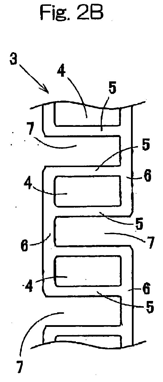
- the roller retainer 3 is of the ladder-like or step-like structure in which pockets 4 are spacedly defined therein in a direction circumferentially thereof and in which axial slits 7, 7A are formed at a plurality of locations in a direction circumferentially thereof so as to extend between the pockets 4 from one axial end or the other axial end of the roller retainer to a position adjacent the opposite axial end or one axial end.
- Fig- 2A illustrates the roller retainer 3, in which the axial slits 7 are formed therein so as to extend from one axial end (a left end as viewed in Fig. 2A) towards the other axial end (a right end as viewed in Fig. 2A) of the roller retainer 3.
- Fig. 2B illustrates the roller retainer 3, in which the axial slits 7 extending from one axial end towards the other axial end of the roller retainer 3 and the axial slits 7 extending from the other axial end towards one axial end of the roller retainer 3 are so arranged to alternate with each other in a direction circumferentially of the roller retainer 3, with the respective pockets 4 intervening therebetween.
- the axial slits 7 are comprised of a segment, in which a portion of the ring part 6 between the neighboring pillars 5 is depleted substantially completely, and a segment which concurrently serves as a pocket between the neighboring pillars 5.
- Fig. 2C illustrates the roller retainer 3, in which the axial slits 7 and 7A extend from one axial end (a left end as viewed in Fig. 2C).
- the axial slits 7 is comprised of a segment, in which a portion of the ring part 6 between the neighboring pillars 5 is depleted substantially completely, and a segment which concurrently serves as a pocket between the neighboring pillars 5.
- the axial slits 7A is comprised a segment, in which a portion of the ring part 6 between the neighboring pillars 5 is depleted partially at a location 6a, and a segment which concurrently serves as a pocket between the neighboring pillars 5.
- the axial slits 7 and 7A are so formed in the roller retainer 3 as to alternate with each other in a direction circumferentially of the roller retainer 3.
- the pockets 4 and the slits 7 are so formed as to alternate with each other in a direction circumferentially of the corresponding roller retainer 3 and each of the pillars 5 is defined between the respective pocket 4 and the neighboring slit 7 which concurrently serves as a pocket.
- each of the slits 7A may be formed every set of the pockets 4 while each of the pillars 5 is provided between the respective pocket 4 and the adjacent slit 7 concurrently serving as a pocket.
- some of the pillars 5 are also provided between the pockets 4 defined continuously in line.
- each of the slits 7 may be formed every set of the pockets 4, not every single pocket 4.
- Each of the pillars 5 positioned between each of the pockets 4 and the associated slit 7 and also between the neighboring pockets 4 may be of a triangular sectional shape, as shown in Fig. 1B.
- Fig. 3 illustrates an explanatory diagram showing one end of the roller retainer 3, where the slits 7 (7A) are formed, before the roller retainer 3 is radially inwardly deformed, shown in comparison with such one end after the roller retainer 3 has been radially inwardly deformed.
- the width W of each of the slits 7 (7A) as measured in a direction circumferentially of the roller retainer 3 and the number of the slits 7 (7A) are so chosen that the outer diameter d16o of a ring body 16 assumed by the ring part 6 if circumferentially extending arcuate portions (ring part 6) excluding the slits 7 (7A) are jointed together can be smaller than the inner diameter d2i of the inscribed circle of the circular row of the rollers 2.
- the pockets 4 and the slits 7 are so formed as to alternate with each other in the circumferential direction such as in the roller retainer 3 shown in any one of Figs.
- the required relation between the outer diameter d16o and the inner diameter d2i can be naturally satisfied, but even in the case of the retainer 3 of Fig. 2C and/or even where the number of the slits 7 is relatively small and/or the opening width W of the slits 7 is small, the required relation between the outer diameter d16o and the inner diameter d2i of the inscribed circle has to be preferably satisfied.
- roller retainer 3 is of a structure in which the slits 7 (7A) are formed
- any one of first and second assembling methods such as shown in Figs. 4 and 5, respectively, can be employed in the practice of the present invention.
- this method is particularly employed to assemble the retainer-equipped roller bearing employing the roller retainer 3 having the slits 7 (7A) defined only at one end thereof such as shown in Figs. 2A and 2C.
- the roller retainer 3 is inserted axially into the circular row of the rollers 2 from the side of one axial end or the openings of the slits 7 (7a).
- Positioning of the rollers 2 inside the outer race 1 is carried out by, for example, applying a grease to each of the rollers 2 and allowing the individual rollers 2 to stick to the inner peripheral surface of the outer race 1 by the effect of an adhesive property exhibited by the applied grease.
- roller retainer 3 The job of inserting the roller retainer 3 into the circular row of the rollers 2 is carried out by radially inwardly constricting such one axial end of the roller retainer 3, which is to be first inserted into the outer race 1, by the use of an expandable chuck 11 having a conical inner surface and then by pushing the roller retainer 3 to a position inside the circular row of the rollers 2 by the use of a pusher jig 12.
- the roller retainer 3 After the insertion of the roller retainer 3, the roller retainer 3 is allowed to restore to the original shape or diameter by the effect of the elasticity owned by the material used to form the roller retainer 3. In this way, the rollers 2 are inserted into and retained in the respective pockets 4 of the roller retainer 3.
- the expandable chuck 11 may be of a type including a plurality of divided chuck segments arranged in a circular row and can be available in the form of a collet chuck.
- the roller retainer 3 can be elastically deformed by the effect of the elasticity possessed by the material used to form the roller retainer 3, a flexure deformation of the roller retainer 3 can advantageously be minimized and an undesirable reduction in shape precision brought about by the deformation can advantageously be prevented, thereby increasing the assemblability and the assembling precision. Also, the first assembling method can be automated.
- Fig. 5 showing the second method of assembling the roller retainer 3. This method is particularly employed to assemble the retainer-equipped roller bearing employing the roller retainer 3 having the slits 7 defined at the opposite axial ends thereof such as shown in Fig. 2B.
- the roller retainer 3 After the insertion of the roller retainer 3, the roller retainer 3 is allowed to restore to the original shape to assume the original diameter by the effect of the elasticity owned by the material used to form the roller retainer 3, to thereby accomplish the insertion of the rollers 2 into the respective pockets 4 in the roller retainer 3.
- the roller bearing can readily be assembled merely by pushing the roller retainer 3 into the guide jig 13, with no need to use any chuck. Even in this case, a flexure deformation of the roller retainer 3 can advantageously be minimized and an undesirable reduction in shape precision brought about by the deformation can advantageously be prevented, thereby increasing the assemblability and the assembling precision.
- roller retainer 3 since the roller retainer 3 has the slits 7 arranged at the opposite axial ends thereof, the roller retainer 3 can be inserted from either one axial end side or the other axial end side during the insertion, allowing the assemblability to be further increased. In addition, even the second assembling method can be automated with a simplified structure.
- Fig. 6 illustrates an assembled condition of the roller retainer 3, in which the rollers 2 have been inserted in the respective pockets 4 of the roller retainer 3.
- Fig. 6A illustrates the roller retainer 3 having the slits 7 defined only at one axial end thereof such as shown in Fig. 2A, in which the rollers 2 are received not only in the pockets 4, but also in the slits 7.
- Fig. 6B illustrates the roller retainer 3 having the slits 7 defined at the opposite axial ends thereof such as shown in Fig. 2B, in which the rollers 2 are received not only in the pockets 4, but also in the slits 7.
- roller bearing so constructed as hereinbefore described, since the pillars 5 present between the neighboring pockets 4 and also between the pockets 4 and the slits 7, 7A are so positioned between the neighboring rollers 2 to retain the rollers 2 in position from the radially inner side of the roller bearing and since the outer diameter d30 of the circle depicted by respective vertexes of the pillars 5 of the roller retainer 3 is chosen to be smaller than the diameter of the pitch circle PCD as hereinbefore described, an undesirable separation or detachment of the rollers 2 from the roller retainer 3 can be effectively prevented.
- the outer race 1 has been described as employed in the form of the press-worked product, the outer race 1 may be produced by grinding, such as shown in Fi.g. 7. Even with the outer race 1 of the machined product, the roller retainer 3 can be incorporated inside the outer race 1 with an increased assemblability and an increased assembling precision..
- At least one of the opposite outer peripheral ends 3a of the roller retainer 3 is preferably so shaped as to represent a chamfered shape which may be either tapered or rounded.
- Fig. 8A illustrates the opposite outer peripheral ends 3 a representing a tapered configuration, which can be employed in the roller retainer 3 having the slits 7 defined at the opposite axial ends thereof such as shown in Fig. 2B.
- the use of the tapered configuration in the opposite outer peripheral ends 3a of the roller retainer 3 is advantageous in that the insertion of the roller retainer 3 into the circular row of the rollers 2 from an axial direction during the assemblage can be accomplished smoothly, resulting in increase of the assemblability. Since the roller retainer 3 of Fig. 2B has the opposite outer peripheral ends 3a tapered, the insertion of the roller retainer 3 into the circular row of the rollers 2 can advantageously be accomplished smoothly in any one of the axial directions. It is to be noted that the outer race 1 of Fig. 8 is produced by grinding.
- Fig. 8B illustrates one of the opposite outer peripheral ends 3a representing a rounded configuration, which can be employed in the roller retainer 3 having the slits 7 defined only at one axial end thereof such as shown in any one of Figs. 2A and 2C.
- the rounded configuration is formed only in one axial end of the roller retainer 3, at which a cutout is made to define the respective slit 7 (7A).
- the roller retainer 3 is inserted into the circular row of the rollers 2 from the side of the openings of the slits 7 (7A). Accordingly, the insertion of the roller retainer 3 can be performed smoothly with the assemblability increased consequently.
- the outer race 1 is employed in the form of the press-worked product.
- the roller retainer 3 may have a split area 8 at one location thereof in the circumferential direction thereof as shown in any one of Figs. 9A to 9C.
- This split area 8 is defined in one or both the ring parts 6 at one side or opposite sides of the pocket 4.
- the split area 8 may be of a design in which a recess 9a defined in one end of the divided ring part 6 of the roller retainer 3 can releasably receive therein a projection 9b defined in the opposite end of the divided ring part 6 as shown in Fig.
- the opposite ends of the divided ring part 6 may have respective projections 9c, which form a halving joint, as shown in Fig. 9B.
- the opposite ends of the divided ring part 6 may be so shaped as to define a respective flat end face so that the opposite ends of the divided ring part 9 can be butt-jointed.
- the roller retainer 3 is shown in a condition where one of the ring parts 6, having the split area 8, is radially inwardly deformed. The split area 8, when an external force applied for the deformation is released, returns to the original condition in which the opposite ends 9a and 9b or 9c and 9c are not in tight contact with each other..
- a roller 2 may be arranged in a pocket equivalent slit having one side surrounded by the ring part 6 having the split area 8 defined therein to open to the other side.
- the roller retainer 3 has been shown and described as satisfying the design condition in which the pillars 5 each between the neighboring pockets 4 retain the rollers from the radially inner side of the roller bearing at respective locations between the rollers 2 and the outer diameter d3o is smaller than the pitch circle diameter PCD.
- the slits 7, 7A or the split area 8 are employed in the roller retainer 3 failing to satisfy the above design condition, the assemblability can be increased as is the case with the foregoing embodiments.
- roller bearing of the present invention can be employed in various applications similar to those in which the conventional full complement roller bearing having the outer race is employed.
- the roller bearing of the present invention can be equally employed in a rear suspension link of a motorcycle, as a rocker arm bearing of a roller type, as a bearing for a seat reclining mechanism and so on.
Abstract

Description
Claims (9)
- A roller bearing comprising:an outer race having a raceway defined therein;a plurality of rollers held in rolling contact with the raceway; anda ring-shaped roller retainer having a plurality of pockets, each rollingly receiving the respective roller, spacedly defined therein in a direction circumferentially thereof to form a ladder-like structure:wherein the roller retainer has a plurality of slits that are spacedly defined in a direction circumferential thereof so as to extend from one axial end or the other axial end of the roller retainer to a position adjacent the other axial end or one axial end.
- The roller bearing as claimed in Claim 1, wherein the roller retainer has pillars, each defined between the neighboring pockets, each of which pillars is positioned between the neighboring rollers to retain the corresponding rollers from a radially inner side of the roller bearing, and also has an outer diameter of a circle depicted by respective pillars of the roller retainer is smaller than the diameter of a pitch circle depicted by a circular row of the rollers.
- The roller bearing as claimed in Claim 1, wherein each of the slits concurrently serves as a pocket for accommodating therein the corresponding roller.
- The roller bearing as claimed in Claim 1, wherein the width of each of the slits as measured in a direction circumferentially of the roller retainer and the number of the slits employed in the roller retainer are so chosen that the outer diameter of a ring body assumed by a ring part of the roller retainer if circumferentially extending arcuate portions of the roller retainer excluding the slits are jointed together may be smaller than the diameter of a circle inscribed by a circular row of the rollers.
- The roller bearing as claimed in Claim 1, wherein at least one of opposite outer peripheral ends of the roller retainer is so chamfered as to represent a tapered shape or a rounded shape.
- A roller bearing comprising:an outer race having a raceway defmed therein;a plurality of rollers held in rolling contact with the raceway; anda ring-shaped roller retainer having a plurality of pockets, each rollingly receiving the respective roller, spacedly defined therein in a direction circumferentially thereof to form a ladder-like structure:wherein the roller retainer has pillars each positioned between the neighboring pockets for retaining the corresponding rollers from a radially inner side of the roller bearing, and an outer diameter of a circle depicted by the respective pillars of the roller retainer is smaller than the diameter of a pitch circle depicted by a circular row of the rollers; andwherein a split area is defined at one location of the roller retainer in a circumferential direction thereof.
- The roller bearing as claimed in Claim 6, wherein one of the rollers is positioned inside the split area in the roller retainer.
- A method of assembling the roller bearing as defined in Claim 2, which has the slits defined only at one axial end of the roller retainer, said method comprising:positioning the rollers inside the outer race to form a circular row of the roller; andinserting the roller retainer axially into the circular row of the rollers by radially inwardly constricting such one axial end of the roller retainer, which is to be first inserted into the outer race, by means of an expandable chuck having a conical inner surface and then by pushing the roller retainer by means of a pusher jig to a position inside the circular row of the rollers and further by allowing the roller retainer to restore to the original shape or diameter by the effect of an elasticity owned by a material used to form the roller retainer.
- A method of assembling the roller bearing as defined in Claim 8, which has the slits defined at the opposite axial ends of the roller retainer, said method comprising:positioning the rollers inside the outer race to form a circular row of the rollers; andinserting the roller retainer axially into the circular row of the rollers by pushing the roller retainer into a guide jig having a conical inner surface while radially inwardly constricting one of the opposite axial ends, which is to be first pushed into the circular row of the rollers, by means of the guide jig and then by allowing the roller retainer to restore to the original shape or diameter by the effect of an elasticity owned by a material used to form the roller retainer
Applications Claiming Priority (2)
| Application Number | Priority Date | Filing Date | Title |
|---|---|---|---|
| JP2004044019A JP2005233322A (en) | 2004-02-20 | 2004-02-20 | Roller bearing and assembling method thereof |
| JP2004044019 | 2004-02-20 |
Publications (2)
| Publication Number | Publication Date |
|---|---|
| EP1566557A1 true EP1566557A1 (en) | 2005-08-24 |
| EP1566557B1 EP1566557B1 (en) | 2008-04-09 |
Family
ID=34709134
Family Applications (1)
| Application Number | Title | Priority Date | Filing Date |
|---|---|---|---|
| EP05003119A Expired - Fee Related EP1566557B1 (en) | 2004-02-20 | 2005-02-15 | Roller bearing and method of assembling the same |
Country Status (4)
| Country | Link |
|---|---|
| US (1) | US7766555B2 (en) |
| EP (1) | EP1566557B1 (en) |
| JP (1) | JP2005233322A (en) |
| DE (1) | DE602005005875T2 (en) |
Cited By (3)
| Publication number | Priority date | Publication date | Assignee | Title |
|---|---|---|---|---|
| EP2312173A1 (en) * | 2006-10-26 | 2011-04-20 | NTN Corporation | Retainer for rocking bearing, and air disc brake |
| EP3040569A4 (en) * | 2013-08-26 | 2016-08-24 | Nsk Ltd | Method for manufacturing shell-type needle bearing, and manufacturing jig used in manufacture of same |
| DE102011077214B4 (en) * | 2010-06-09 | 2018-01-04 | Aktiebolaget Skf | Cylindrical roller bearings |
Families Citing this family (9)
| Publication number | Priority date | Publication date | Assignee | Title |
|---|---|---|---|---|
| JP2005233322A (en) | 2004-02-20 | 2005-09-02 | Ntn Corp | Roller bearing and assembling method thereof |
| JP2005249163A (en) * | 2004-03-08 | 2005-09-15 | Ntn Corp | Roller bearing |
| US8044544B2 (en) * | 2005-09-15 | 2011-10-25 | Ntn Corporation | Rolling bearing, spindle support structure of main motor for railway vehicle, and bearing structure |
| JP2012077882A (en) * | 2010-10-05 | 2012-04-19 | Jtekt Corp | Roller bearing cage and roller bearing |
| BR112014014728A2 (en) | 2011-12-20 | 2017-06-13 | Koninklijke Philips Nv | imaging system; and method |
| JP6146013B2 (en) * | 2012-05-28 | 2017-06-14 | 株式会社ジェイテクト | Roller bearing cage and rolling bearing provided with the cage |
| JP6253877B2 (en) * | 2012-10-24 | 2017-12-27 | Ntn株式会社 | Cylindrical roller bearing |
| US10415429B2 (en) | 2015-09-25 | 2019-09-17 | General Electric Company | Planet gearbox with cylindrical roller bearing with high density roller packing |
| DE102019106487A1 (en) * | 2019-03-14 | 2020-09-17 | Schaeffler Technologies AG & Co. KG | Rolling bearing cage |
Citations (8)
| Publication number | Priority date | Publication date | Assignee | Title |
|---|---|---|---|---|
| GB445090A (en) * | 1934-10-18 | 1936-04-02 | Skf Svenska Kullagerfab Ab | Improvements in or relating to anti-friction bearing cages |
| US3353881A (en) * | 1964-05-30 | 1967-11-21 | Schaeffler Ohg Industriewerk | Cage for roller bearings |
| JPS5676720A (en) * | 1979-11-22 | 1981-06-24 | Ntn Toyo Bearing Co Ltd | Retainer for conical roller bearing and manufacture of said retainer |
| JPH06307456A (en) * | 1993-04-23 | 1994-11-01 | Ntn Corp | Shell-shaped roller bearing and manufacture thereof |
| DE19506796A1 (en) * | 1994-02-28 | 1995-10-05 | Ntn Toyo Bearing Co Ltd | Bearing for roller bodies with outer ring and track |
| DE19641546A1 (en) * | 1996-10-09 | 1998-04-16 | Schaeffler Waelzlager Ohg | Method of manufacturing a cylindrical roller bearing |
| US5743660A (en) * | 1996-02-09 | 1998-04-28 | Skf Gmbh | Cage for roller bearing assembly |
| JP2001140900A (en) * | 1999-11-12 | 2001-05-22 | Nsk Ltd | Tapered roller bearing and method of assembly |
Family Cites Families (42)
| Publication number | Priority date | Publication date | Assignee | Title |
|---|---|---|---|---|
| US612472A (en) * | 1898-10-18 | woodcock | ||
| US1426578A (en) * | 1922-08-22 | Chables i | ||
| US1173719A (en) * | 1912-04-30 | 1916-02-29 | Norma Cie Gmbh | Roller-bearing cage. |
| US1426595A (en) | 1921-08-18 | 1922-08-22 | Arthur M Patureau | Shutter for motion-picture machines |
| US1928823A (en) * | 1929-07-18 | 1933-10-03 | Gen Motors Corp | Antifriction bearing cage and method |
| US1894595A (en) * | 1929-08-05 | 1933-01-17 | F L Mclaughlin Corp | Roller bearing cage and method of forming the same |
| US2540283A (en) * | 1946-12-05 | 1951-02-06 | Int Harvester Co | Roller bearing |
| US2503070A (en) * | 1949-01-19 | 1950-04-04 | Reiss Christian Henry | Roller bearing and roller cage therefor |
| US3102760A (en) * | 1961-03-23 | 1963-09-03 | Federal Mogul Bower Bearings | Cage for straight roller bearing |
| JPS4427290Y1 (en) | 1965-11-04 | 1969-11-14 | ||
| US3399008A (en) * | 1966-06-15 | 1968-08-27 | Skf Ind Inc | Roller cage assembly |
| US3477773A (en) * | 1968-01-23 | 1969-11-11 | John A Altson | Molded cage for nonseparable assembly of roller bearings |
| GB1604570A (en) | 1978-05-31 | 1981-12-09 | Ransome Hoffmann Pollard | Production and assembly of rolling element bearings |
| US4277116A (en) * | 1979-10-17 | 1981-07-07 | Cummins Engine Company, Inc. | Bearing construction and retainer therefor |
| JPS57163727A (en) | 1981-04-02 | 1982-10-08 | Ntn Toyo Bearing Co Ltd | Retainer for roller bearing and its fitting |
| JPS58102824A (en) | 1981-12-14 | 1983-06-18 | Koyo Seiko Co Ltd | Manufacture of synthetic resinous retainer |
| US4541743A (en) * | 1983-07-20 | 1985-09-17 | Nippon Seiko Kabushiki Kaisha | Plastic retainer for roller bearing |
| JPH022538U (en) * | 1988-06-16 | 1990-01-09 | ||
| US4881830A (en) * | 1989-01-31 | 1989-11-21 | The Torrington Company | Split ring roller bearing cage |
| DE3925512C2 (en) * | 1989-08-02 | 1997-12-11 | Skf Gmbh | Cage |
| DE4133443C2 (en) * | 1991-10-09 | 1995-07-13 | Schaeffler Waelzlager Kg | Cage for full complement roller bearings |
| JPH08326744A (en) | 1995-05-31 | 1996-12-10 | Ntn Corp | Shell-type needle roller bearing |
| JP3007580B2 (en) * | 1996-12-20 | 2000-02-07 | 株式会社シマノ | Telescopic retainer for bearing |
| US6102579A (en) * | 1997-01-10 | 2000-08-15 | The Torrington Company | Cage or set of rollers for roller bearings |
| EP0992696B1 (en) * | 1997-07-01 | 2007-02-28 | JTEKT Corporation | Bearing retainer of synthetic resin, method of manufacturing the same, and roller bearing |
| US6179474B1 (en) * | 1997-11-21 | 2001-01-30 | The Torrington Company | High capacity roller bearing |
| US6053956A (en) | 1998-05-19 | 2000-04-25 | 3M Innovative Properties Company | Method for making abrasive grain using impregnation and abrasive articles |
| DE19824070A1 (en) | 1998-05-29 | 1999-12-02 | Spinea S R O Kosice | roller bearing |
| JPH11344029A (en) | 1998-05-29 | 1999-12-14 | Ntn Corp | Thrust roller bearing |
| JP4087521B2 (en) | 1998-12-17 | 2008-05-21 | Ntn株式会社 | Needle roller with cage and speed reducer using the same |
| JP2000213545A (en) | 1999-01-25 | 2000-08-02 | Nsk Ltd | Retainer for roller bearing |
| JP2000320558A (en) | 1999-05-14 | 2000-11-24 | Nsk Ltd | Synthetic resin made retainer for roller bearing |
| DE10011651B4 (en) * | 2000-03-10 | 2009-12-24 | Schaeffler Kg | Rotationally symmetrical molded part |
| JP4464557B2 (en) * | 2000-12-28 | 2010-05-19 | 日本トムソン株式会社 | Roller bearing cage |
| JP4618915B2 (en) | 2001-03-14 | 2011-01-26 | Ntn株式会社 | Full roller bearing and planetary gear reduction device using the same |
| US6857785B2 (en) * | 2001-03-27 | 2005-02-22 | Ntn Corporation | Caged roller assembly and reduction gear unit using the same |
| JP4087630B2 (en) | 2001-03-27 | 2008-05-21 | Ntn株式会社 | Roller with cage and speed reducer using the same |
| DE10119889B4 (en) | 2001-04-24 | 2004-02-19 | Aktiebolaget Skf | roller bearing |
| JP2005054871A (en) | 2003-08-04 | 2005-03-03 | Ntn Corp | Roller bearing |
| JP2005233322A (en) | 2004-02-20 | 2005-09-02 | Ntn Corp | Roller bearing and assembling method thereof |
| JP2005249163A (en) | 2004-03-08 | 2005-09-15 | Ntn Corp | Roller bearing |
| JP2006144839A (en) * | 2004-11-17 | 2006-06-08 | Ntn Corp | Roller bearing |
-
2004
- 2004-02-20 JP JP2004044019A patent/JP2005233322A/en active Pending
-
2005
- 2005-02-09 US US11/052,771 patent/US7766555B2/en not_active Expired - Fee Related
- 2005-02-15 EP EP05003119A patent/EP1566557B1/en not_active Expired - Fee Related
- 2005-02-15 DE DE602005005875T patent/DE602005005875T2/en active Active
Patent Citations (8)
| Publication number | Priority date | Publication date | Assignee | Title |
|---|---|---|---|---|
| GB445090A (en) * | 1934-10-18 | 1936-04-02 | Skf Svenska Kullagerfab Ab | Improvements in or relating to anti-friction bearing cages |
| US3353881A (en) * | 1964-05-30 | 1967-11-21 | Schaeffler Ohg Industriewerk | Cage for roller bearings |
| JPS5676720A (en) * | 1979-11-22 | 1981-06-24 | Ntn Toyo Bearing Co Ltd | Retainer for conical roller bearing and manufacture of said retainer |
| JPH06307456A (en) * | 1993-04-23 | 1994-11-01 | Ntn Corp | Shell-shaped roller bearing and manufacture thereof |
| DE19506796A1 (en) * | 1994-02-28 | 1995-10-05 | Ntn Toyo Bearing Co Ltd | Bearing for roller bodies with outer ring and track |
| US5743660A (en) * | 1996-02-09 | 1998-04-28 | Skf Gmbh | Cage for roller bearing assembly |
| DE19641546A1 (en) * | 1996-10-09 | 1998-04-16 | Schaeffler Waelzlager Ohg | Method of manufacturing a cylindrical roller bearing |
| JP2001140900A (en) * | 1999-11-12 | 2001-05-22 | Nsk Ltd | Tapered roller bearing and method of assembly |
Non-Patent Citations (3)
| Title |
|---|
| PATENT ABSTRACTS OF JAPAN vol. 005, no. 147 (M - 088) 17 September 1981 (1981-09-17) * |
| PATENT ABSTRACTS OF JAPAN vol. 1995, no. 02 31 March 1995 (1995-03-31) * |
| PATENT ABSTRACTS OF JAPAN vol. 2000, no. 22 9 March 2001 (2001-03-09) * |
Cited By (5)
| Publication number | Priority date | Publication date | Assignee | Title |
|---|---|---|---|---|
| EP2312173A1 (en) * | 2006-10-26 | 2011-04-20 | NTN Corporation | Retainer for rocking bearing, and air disc brake |
| US8313246B2 (en) | 2006-10-26 | 2012-11-20 | Ntn Corporation | Rocker bearing with outer ring and air disk brake system |
| CN103148103A (en) * | 2006-10-26 | 2013-06-12 | Ntn株式会社 | Outer ring for rocking bearing, retainer for rocking bearing, rocking bearing, and air disc brake |
| DE102011077214B4 (en) * | 2010-06-09 | 2018-01-04 | Aktiebolaget Skf | Cylindrical roller bearings |
| EP3040569A4 (en) * | 2013-08-26 | 2016-08-24 | Nsk Ltd | Method for manufacturing shell-type needle bearing, and manufacturing jig used in manufacture of same |
Also Published As
| Publication number | Publication date |
|---|---|
| DE602005005875T2 (en) | 2009-06-04 |
| DE602005005875D1 (en) | 2008-05-21 |
| US7766555B2 (en) | 2010-08-03 |
| US20050185875A1 (en) | 2005-08-25 |
| EP1566557B1 (en) | 2008-04-09 |
| JP2005233322A (en) | 2005-09-02 |
Similar Documents
| Publication | Publication Date | Title |
|---|---|---|
| US7766555B2 (en) | Roller bearing and method of assembling the same | |
| US7220060B2 (en) | Roller bearing | |
| US7390127B2 (en) | Roller bearing assembly | |
| EP1757823B2 (en) | Tapered roller bearing | |
| JP5702534B2 (en) | Tapered roller bearing split cage | |
| EP1881216A2 (en) | Cage for roller bearing | |
| EP2489891B1 (en) | Rolling bearing | |
| CN105987075B (en) | Tapered roller bearing | |
| GB2178491A (en) | A radial rolling bearing | |
| US6857785B2 (en) | Caged roller assembly and reduction gear unit using the same | |
| US6367982B1 (en) | Cylindrical roller bearing | |
| JP5531551B2 (en) | Roller bearing cage, inner ring assembly, outer ring assembly and rolling bearing provided with the cage | |
| GB2503088A (en) | A two-piece rolling element cage | |
| JP2003239989A (en) | Roller and retainer assembly body for thrust bearing | |
| JP4244955B2 (en) | Assembly method for automotive hub unit | |
| JP2008038978A (en) | Antifriction bearing | |
| JP2013096505A (en) | Cage for thrust bearing, thrust bearing and three-row composite cylindrical roller bearing using the same | |
| JP2008232171A (en) | Roller bearing | |
| JP2007332994A (en) | Retainer for rolling bearing, and rolling bearing | |
| JP2005054871A (en) | Roller bearing | |
| JP5821178B2 (en) | Bearing spacer | |
| JP2019158082A (en) | Tapered roller bearing | |
| JP2007205535A (en) | Cage for rolling bearing, and rolling bearing | |
| JP2009092088A (en) | Radial roller bearing with holder | |
| JP2018155380A (en) | Spherical slide bearing |
Legal Events
| Date | Code | Title | Description |
|---|---|---|---|
| PUAI | Public reference made under article 153(3) epc to a published international application that has entered the european phase |
Free format text: ORIGINAL CODE: 0009012 |
|
| AK | Designated contracting states |
Kind code of ref document: A1 Designated state(s): AT BE BG CH CY CZ DE DK EE ES FI FR GB GR HU IE IS IT LI LT LU MC NL PL PT RO SE SI SK TR |
|
| AX | Request for extension of the european patent |
Extension state: AL BA HR LV MK YU |
|
| 17P | Request for examination filed |
Effective date: 20060118 |
|
| AKX | Designation fees paid |
Designated state(s): DE FR |
|
| 17Q | First examination report despatched |
Effective date: 20060707 |
|
| 17Q | First examination report despatched |
Effective date: 20060707 |
|
| GRAP | Despatch of communication of intention to grant a patent |
Free format text: ORIGINAL CODE: EPIDOSNIGR1 |
|
| GRAS | Grant fee paid |
Free format text: ORIGINAL CODE: EPIDOSNIGR3 |
|
| GRAA | (expected) grant |
Free format text: ORIGINAL CODE: 0009210 |
|
| AK | Designated contracting states |
Kind code of ref document: B1 Designated state(s): DE FR |
|
| REF | Corresponds to: |
Ref document number: 602005005875 Country of ref document: DE Date of ref document: 20080521 Kind code of ref document: P |
|
| ET | Fr: translation filed | ||
| PLBE | No opposition filed within time limit |
Free format text: ORIGINAL CODE: 0009261 |
|
| STAA | Information on the status of an ep patent application or granted ep patent |
Free format text: STATUS: NO OPPOSITION FILED WITHIN TIME LIMIT |
|
| 26N | No opposition filed |
Effective date: 20090112 |
|
| PGFP | Annual fee paid to national office [announced via postgrant information from national office to epo] |
Ref country code: FR Payment date: 20120221 Year of fee payment: 8 |
|
| PGFP | Annual fee paid to national office [announced via postgrant information from national office to epo] |
Ref country code: DE Payment date: 20120208 Year of fee payment: 8 |
|
| REG | Reference to a national code |
Ref country code: FR Ref legal event code: ST Effective date: 20131031 |
|
| REG | Reference to a national code |
Ref country code: DE Ref legal event code: R119 Ref document number: 602005005875 Country of ref document: DE Effective date: 20130903 |
|
| PG25 | Lapsed in a contracting state [announced via postgrant information from national office to epo] |
Ref country code: FR Free format text: LAPSE BECAUSE OF NON-PAYMENT OF DUE FEES Effective date: 20130228 Ref country code: DE Free format text: LAPSE BECAUSE OF NON-PAYMENT OF DUE FEES Effective date: 20130903 |