EP1566333A1 - Dispositif d'échappement sous marin. - Google Patents
Dispositif d'échappement sous marin. Download PDFInfo
- Publication number
- EP1566333A1 EP1566333A1 EP05300083A EP05300083A EP1566333A1 EP 1566333 A1 EP1566333 A1 EP 1566333A1 EP 05300083 A EP05300083 A EP 05300083A EP 05300083 A EP05300083 A EP 05300083A EP 1566333 A1 EP1566333 A1 EP 1566333A1
- Authority
- EP
- European Patent Office
- Prior art keywords
- exhaust
- hull
- ship
- deflector
- box
- Prior art date
- Legal status (The legal status is an assumption and is not a legal conclusion. Google has not performed a legal analysis and makes no representation as to the accuracy of the status listed.)
- Granted
Links
- XLYOFNOQVPJJNP-UHFFFAOYSA-N water Substances O XLYOFNOQVPJJNP-UHFFFAOYSA-N 0.000 claims description 16
- 239000007789 gas Substances 0.000 description 9
- 239000000779 smoke Substances 0.000 description 3
- 238000009423 ventilation Methods 0.000 description 2
- 230000006866 deterioration Effects 0.000 description 1
- 239000006185 dispersion Substances 0.000 description 1
- 238000005188 flotation Methods 0.000 description 1
- 235000019645 odor Nutrition 0.000 description 1
- 238000005457 optimization Methods 0.000 description 1
- 230000035943 smell Effects 0.000 description 1
- 230000001052 transient effect Effects 0.000 description 1
- 238000011144 upstream manufacturing Methods 0.000 description 1
Images

Classifications
-
- B—PERFORMING OPERATIONS; TRANSPORTING
- B63—SHIPS OR OTHER WATERBORNE VESSELS; RELATED EQUIPMENT
- B63H—MARINE PROPULSION OR STEERING
- B63H21/00—Use of propulsion power plant or units on vessels
- B63H21/32—Arrangements of propulsion power-unit exhaust uptakes; Funnels peculiar to vessels
Definitions
- the present invention relates to ships and more especially the exhaust of said vessels.
- Air exhaust has the disadvantage of being noisy, generate unpleasant smells and create plumes of smoke which are not aesthetic and are easily identifiable.
- Submarine exhausts only work at high speeds (generally at speeds above 9 knots) are placed near the waterline and have an outer part called deflector or "spoon" outside to prevent the entry of water into the exhaust and protect the engines against the pressure exerted by the water.
- This system although easy to perform, is very sensitive to movements of the ship and the swell, as there is a risk introduction of water into the engines.
- the position close to the line of flotation creates a risk of blockage by ice deterioration of the external duct by floating objects or simply the edge of the dock. Odors are not totally suppressed because of the low dispersion of the gases in the water.
- the movement of the ship and the swell can clear the escape of the water the smoke is then directly in the air.
- the object of the present invention is to propose a device underwater exhaust at the same time simple, operating at low speed and releasing little smoke in the air near the ship.
- the underwater escape device is consisting of an exhaust box connected to the evacuation network gases via an exhaust pipe, said box is disposed at level of an exhaust outlet located on the hull of a ship she is equipped with a baffle located tangentially to said hull.
- the tangential deflector gives a smooth profile to the hull of the ship which allows to go into submarine mode at low speeds and which avoids the risk of collision with floating objects.
- the deflector has the shape of an inverted spoon.
- the shape substantially convex from the outside of the spoon accelerates the flow of the interior of the exhaust and promotes the evacuation of water, while the shape hollow from the inside of the spoon takes off the water nets from the hull and creates a ventilation zone at the back of the profile.
- the profile ensures a sufficient vacuum zone inside the duct exhaust for the evacuation of gases.
- the deflector has a width horizontal equivalent to 2/3 of the horizontal width of the exit exhaust. This size is optimal to facilitate the evacuation of gas without driving water inlet into the exhaust box.
- the exhaust duct is horizontal.
- the exhaust is placed below the waterline.
- the very deep position of the exhaust outlet makes it possible to reduce external noise, discharges into the atmosphere, and to remove both the risk of passage in the open in case of ship movements or swell and the risk to be caught in the ice.
- the exhaust is located at more 50cm from the waterline.
- the exhaust duct makes a angle of 30 to 40 ° with respect to the hull of the ship. This inclination horizontal exhaust duct relative to the baffle allows flow optimization.
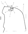
- the ship 1 has an exhaust 2 disposed below the level of the waterline 3 at a distance from said surface (cf. figure 1).
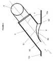
- the exhaust 2 comprises an exhaust pipe 4 and connected to the exhaust network 8 of the gases and a box 5 arranged inside at the exhaust outlet 7 and not exceeding not the hull 10 of the ship 1 (see Figure 2).
- the duct 4 and the box 5 angle ⁇ with the shell 10.
- the angle ⁇ is measured from the front portion 10a of the hull 10 and is between 30 and 40 °.
- the box 5 is partially closed by a deflector 6 fixed on the side of the box 5 at the level of the part before 10a.
- the deflector 6 is oriented towards the front of the ship 1 of such way that when moving the vessel 1 the water inlet is minimal.
- the deflector 6 has the shape of a spoon whose hollow part 60 is in the extension of the part 10a of the hull 10 and directed to the outside of the ship 1.
- the convex part 61 is placed inside of the hull 10.
- the two faces 60 and 61 of the deflector 6 converge towards the rear of the ship 1 so that the front face 62 of the deflector 6 is wider than the rear part 63.
- the network Exhaust 2 goes into submarine mode by opening or not valve (not shown) disposed further upstream and the gases exit through the duct 4 and the box 5 where the depression is sufficient to receive the exhaust gas.
- the profile 61 directs the gases towards the rear of the vessel 1 and part 60 deflects the water streams in such a way that both flows are almost tangent when they come in contact with each other the other, which also promotes flow and limits drag.
Landscapes
- Chemical & Material Sciences (AREA)
- Engineering & Computer Science (AREA)
- Combustion & Propulsion (AREA)
- Mechanical Engineering (AREA)
- Ocean & Marine Engineering (AREA)
- Exhaust Silencers (AREA)
- Treating Waste Gases (AREA)
- Electrical Discharge Machining, Electrochemical Machining, And Combined Machining (AREA)
- Incineration Of Waste (AREA)
Abstract
Description
- la figure 1 est une vue en coupe de profil du navire,
- la figure 2 est une vue de dessus de l'échappement selon l'invention,
- les figures 3 et 4 sont des vues de dessus de l'échappement fermé et ouvert.
Claims (7)
- Dispositif d'échappement sous marin (2) constitué d'une boite d'échappement (5) connectée au réseau d'évacuation (8) des gaz via un conduit d'échappement (4), la dite boite (5) est disposé au niveau d'une sortie d'échappement (9) située sur la coque (10) d'un navire (1) caractérisé en ce que la boite d'échappement (5) est équipée d'un déflecteur (6) situé tangentiellement à ladite coque (10).
- Dispositif d'échappement (2) selon la revendication 1 caractérisé en ce que le déflecteur (6) a la forme d'une cuillère inversée.
- Dispositif d'échappement (2) selon une des revendications précédentes caractérisé en ce que le déflecteur (6) a une largeur horizontale équivalent au 2/3 de la largeur horizontale de la sortie d'échappement (7).
- Dispositif d'échappement (2) selon une des revendications précédentes caractérisé en ce que le conduit d'échappement (4) est horizontal.
- Dispositif d'échappement (2) selon une des revendications précédentes caractérisé en ce que la sortie d'échappement (7) est placé en dessous de la ligne de flottaison (3).
- Dispositif d'échappement (2) selon la revendication précédente caractérisé en ce que la sortie d'échappement (7) est situé à plus de 50cm de la ligne de flottaison (3).
- Dispositif d'échappement (2) selon une des revendications précédentes caractérisé en ce que l'échappement (2) fait un angle de 30 à 40° par rapport à la coque (10) du navire (1).
Applications Claiming Priority (2)
| Application Number | Priority Date | Filing Date | Title |
|---|---|---|---|
| FR0450305A FR2866625B1 (fr) | 2004-02-19 | 2004-02-19 | Dispositif d'echappement sous marin |
| FR0450305 | 2004-02-19 |
Publications (2)
| Publication Number | Publication Date |
|---|---|
| EP1566333A1 true EP1566333A1 (fr) | 2005-08-24 |
| EP1566333B1 EP1566333B1 (fr) | 2008-07-09 |
Family
ID=34708048
Family Applications (1)
| Application Number | Title | Priority Date | Filing Date |
|---|---|---|---|
| EP05300083A Expired - Lifetime EP1566333B1 (fr) | 2004-02-19 | 2005-02-02 | Dispositif d'échappement sous marin. |
Country Status (7)
| Country | Link |
|---|---|
| EP (1) | EP1566333B1 (fr) |
| AT (1) | ATE400496T1 (fr) |
| AU (1) | AU2005200630B2 (fr) |
| DE (1) | DE602005007946D1 (fr) |
| DK (1) | DK1566333T3 (fr) |
| ES (1) | ES2309689T3 (fr) |
| FR (1) | FR2866625B1 (fr) |
Cited By (2)
| Publication number | Priority date | Publication date | Assignee | Title |
|---|---|---|---|---|
| DE102007020869B3 (de) * | 2007-05-04 | 2008-04-30 | Blohm + Voss Gmbh | Vorrichtung für Schiffe mit Öffnungen zum Ableiten von Medien |
| CN105438428A (zh) * | 2015-01-16 | 2016-03-30 | 刘广 | 通气管圈 |
Citations (3)
| Publication number | Priority date | Publication date | Assignee | Title |
|---|---|---|---|---|
| US5591058A (en) * | 1995-08-18 | 1997-01-07 | Schriever; Frederick G. | Exhaust accessory for boats |
| US5676575A (en) * | 1994-03-08 | 1997-10-14 | Sanshin Kogyo Kabushiki Kaisha | Exhaust system for watercraft |
| EP0921068A2 (fr) * | 1997-12-05 | 1999-06-09 | Peter Müller | Volet compensateur et système d'échappement variable, spécialement pour bateaux et yachts à moteur |
-
2004
- 2004-02-19 FR FR0450305A patent/FR2866625B1/fr not_active Expired - Fee Related
-
2005
- 2005-02-02 DK DK05300083T patent/DK1566333T3/da active
- 2005-02-02 ES ES05300083T patent/ES2309689T3/es not_active Expired - Lifetime
- 2005-02-02 DE DE602005007946T patent/DE602005007946D1/de not_active Expired - Lifetime
- 2005-02-02 AT AT05300083T patent/ATE400496T1/de not_active IP Right Cessation
- 2005-02-02 EP EP05300083A patent/EP1566333B1/fr not_active Expired - Lifetime
- 2005-02-11 AU AU2005200630A patent/AU2005200630B2/en not_active Ceased
Patent Citations (3)
| Publication number | Priority date | Publication date | Assignee | Title |
|---|---|---|---|---|
| US5676575A (en) * | 1994-03-08 | 1997-10-14 | Sanshin Kogyo Kabushiki Kaisha | Exhaust system for watercraft |
| US5591058A (en) * | 1995-08-18 | 1997-01-07 | Schriever; Frederick G. | Exhaust accessory for boats |
| EP0921068A2 (fr) * | 1997-12-05 | 1999-06-09 | Peter Müller | Volet compensateur et système d'échappement variable, spécialement pour bateaux et yachts à moteur |
Cited By (4)
| Publication number | Priority date | Publication date | Assignee | Title |
|---|---|---|---|---|
| DE102007020869B3 (de) * | 2007-05-04 | 2008-04-30 | Blohm + Voss Gmbh | Vorrichtung für Schiffe mit Öffnungen zum Ableiten von Medien |
| EP1988010A2 (fr) | 2007-05-04 | 2008-11-05 | Blohm + Voss Shipyards GmbH | Dispositif pour bateaux dotés d'ouvertures destinées au déchargement de supports |
| EP1988010A3 (fr) * | 2007-05-04 | 2013-06-26 | Blohm + Voss Shipyards GmbH | Dispositif pour bateaux dotés d'ouvertures destinées au déchargement de supports |
| CN105438428A (zh) * | 2015-01-16 | 2016-03-30 | 刘广 | 通气管圈 |
Also Published As
| Publication number | Publication date |
|---|---|
| EP1566333B1 (fr) | 2008-07-09 |
| DE602005007946D1 (de) | 2008-08-21 |
| FR2866625A1 (fr) | 2005-08-26 |
| DK1566333T3 (da) | 2008-11-17 |
| AU2005200630A1 (en) | 2005-09-08 |
| ES2309689T3 (es) | 2008-12-16 |
| ATE400496T1 (de) | 2008-07-15 |
| FR2866625B1 (fr) | 2006-04-28 |
| AU2005200630B2 (en) | 2010-07-08 |
Similar Documents
| Publication | Publication Date | Title |
|---|---|---|
| EP1881179B1 (fr) | Système de ventilation de paroi de chambre de combustion dans une turbomachine | |
| EP2875220B1 (fr) | Reservoir de degazage, et systeme de refroidissement de vehicule automobile equipe d'un tel reservoir de degazage | |
| CA2690601A1 (fr) | Turbojet engine for aircraft | |
| EP2809999A1 (fr) | Brise-jet dispose a l'entree d'eau dans un reservoir de stockage d'eau chaude | |
| CA2639169C (fr) | Turbomachine a double flux a reduction de bruit de jet | |
| FR3100289B1 (fr) | Dispositif éolien pour la récupération de l’énergie éolienne pour des bâtiments | |
| EP1859984A1 (fr) | Ensemble d'admission d'air comburant pour motocyclette et motocyclette equipée d'un tel ensemble | |
| EP1566333B1 (fr) | Dispositif d'échappement sous marin. | |
| CA2489717C (fr) | Drain notamment pour mat support de reacteur | |
| WO2008152460A1 (fr) | Dispositif réduisant la pénétration d'un fluide dans un canal | |
| EP1748153A1 (fr) | Aube de turbomachine et turbomachine comprenant une telle aube | |
| EP1236953A1 (fr) | Bloc avant comprenant au moins un bloc optique et des moyens pour y créer un écoulement d'air, et véhicule automobile correspondant | |
| EP2122226A2 (fr) | Conduit de ventilation comportant des moyens d'attenuation de bruit | |
| EP1143153A1 (fr) | Dispositif pour diminuer les vibrations et les à-coups dans un réseau de conduit pour fluide gazeux, té et réseau de conduit ainsi équipé | |
| EP0733527A1 (fr) | Gicleur pour véhicule | |
| EP0764819B1 (fr) | Dispositif régulateur de débit d'air perfectionné | |
| EP0762048B1 (fr) | Projecteur équipé de moyens de ventilation perfectionnés, notamment pour véhicule | |
| FR3116767A1 (fr) | Diffuseur d’air a reduction de bruit | |
| FR3123092A1 (fr) | Dispositif d’entrainement d’un flux d’air principal pour une turbomachine d’aeronef | |
| FR2682077A1 (fr) | Dispositif d'echappement sous-marin pour moteur a combustion interne d'un navire. | |
| EP2309178B1 (fr) | Dispostif d'éclairage et/ou de signalisaiton d'un véhicule automobile | |
| FR3133904A1 (fr) | Vehicule automobile comprenant un aerateur de planche de bord | |
| EP2020377A1 (fr) | Dalot d'évacuation d'eau, notamment pour bateau | |
| FR2751732A1 (fr) | Dispositif de ventilation a carenage optimise | |
| WO2025253061A1 (fr) | Nacelle pour turbomachine |
Legal Events
| Date | Code | Title | Description |
|---|---|---|---|
| PUAI | Public reference made under article 153(3) epc to a published international application that has entered the european phase |
Free format text: ORIGINAL CODE: 0009012 |
|
| AK | Designated contracting states |
Kind code of ref document: A1 Designated state(s): AT BE BG CH CY CZ DE DK EE ES FI FR GB GR HU IE IS IT LI LT LU MC NL PL PT RO SE SI SK TR |
|
| AX | Request for extension of the european patent |
Extension state: AL BA HR LV MK YU |
|
| RAP1 | Party data changed (applicant data changed or rights of an application transferred) |
Owner name: CHANTIERS DE L'ATLANTIQUE |
|
| 17P | Request for examination filed |
Effective date: 20060111 |
|
| AKX | Designation fees paid |
Designated state(s): AT BE BG CH CY CZ DE DK EE ES FI FR GB GR HU IE IS IT LI LT LU MC NL PL PT RO SE SI SK TR |
|
| RAP1 | Party data changed (applicant data changed or rights of an application transferred) |
Owner name: AKER YARDS S.A. |
|
| 17Q | First examination report despatched |
Effective date: 20070913 |
|
| GRAP | Despatch of communication of intention to grant a patent |
Free format text: ORIGINAL CODE: EPIDOSNIGR1 |
|
| GRAS | Grant fee paid |
Free format text: ORIGINAL CODE: EPIDOSNIGR3 |
|
| GRAA | (expected) grant |
Free format text: ORIGINAL CODE: 0009210 |
|
| AK | Designated contracting states |
Kind code of ref document: B1 Designated state(s): AT BE BG CH CY CZ DE DK EE ES FI FR GB GR HU IE IS IT LI LT LU MC NL PL PT RO SE SI SK TR |
|
| REG | Reference to a national code |
Ref country code: GB Ref legal event code: FG4D Free format text: NOT ENGLISH |
|
| REG | Reference to a national code |
Ref country code: CH Ref legal event code: EP |
|
| REF | Corresponds to: |
Ref document number: 602005007946 Country of ref document: DE Date of ref document: 20080821 Kind code of ref document: P |
|
| REG | Reference to a national code |
Ref country code: IE Ref legal event code: FG4D Free format text: LANGUAGE OF EP DOCUMENT: FRENCH |
|
| REG | Reference to a national code |
Ref country code: DK Ref legal event code: T3 |
|
| REG | Reference to a national code |
Ref country code: ES Ref legal event code: FG2A Ref document number: 2309689 Country of ref document: ES Kind code of ref document: T3 |
|
| PG25 | Lapsed in a contracting state [announced via postgrant information from national office to epo] |
Ref country code: IS Free format text: LAPSE BECAUSE OF FAILURE TO SUBMIT A TRANSLATION OF THE DESCRIPTION OR TO PAY THE FEE WITHIN THE PRESCRIBED TIME-LIMIT Effective date: 20081109 Ref country code: LT Free format text: LAPSE BECAUSE OF FAILURE TO SUBMIT A TRANSLATION OF THE DESCRIPTION OR TO PAY THE FEE WITHIN THE PRESCRIBED TIME-LIMIT Effective date: 20080709 |
|
| PG25 | Lapsed in a contracting state [announced via postgrant information from national office to epo] |
Ref country code: SI Free format text: LAPSE BECAUSE OF FAILURE TO SUBMIT A TRANSLATION OF THE DESCRIPTION OR TO PAY THE FEE WITHIN THE PRESCRIBED TIME-LIMIT Effective date: 20080709 Ref country code: AT Free format text: LAPSE BECAUSE OF FAILURE TO SUBMIT A TRANSLATION OF THE DESCRIPTION OR TO PAY THE FEE WITHIN THE PRESCRIBED TIME-LIMIT Effective date: 20080709 Ref country code: BG Free format text: LAPSE BECAUSE OF FAILURE TO SUBMIT A TRANSLATION OF THE DESCRIPTION OR TO PAY THE FEE WITHIN THE PRESCRIBED TIME-LIMIT Effective date: 20081009 Ref country code: PT Free format text: LAPSE BECAUSE OF FAILURE TO SUBMIT A TRANSLATION OF THE DESCRIPTION OR TO PAY THE FEE WITHIN THE PRESCRIBED TIME-LIMIT Effective date: 20081209 |
|
| REG | Reference to a national code |
Ref country code: IE Ref legal event code: FD4D |
|
| PG25 | Lapsed in a contracting state [announced via postgrant information from national office to epo] |
Ref country code: EE Free format text: LAPSE BECAUSE OF FAILURE TO SUBMIT A TRANSLATION OF THE DESCRIPTION OR TO PAY THE FEE WITHIN THE PRESCRIBED TIME-LIMIT Effective date: 20080709 Ref country code: IE Free format text: LAPSE BECAUSE OF FAILURE TO SUBMIT A TRANSLATION OF THE DESCRIPTION OR TO PAY THE FEE WITHIN THE PRESCRIBED TIME-LIMIT Effective date: 20080709 |
|
| PLBE | No opposition filed within time limit |
Free format text: ORIGINAL CODE: 0009261 |
|
| STAA | Information on the status of an ep patent application or granted ep patent |
Free format text: STATUS: NO OPPOSITION FILED WITHIN TIME LIMIT |
|
| PG25 | Lapsed in a contracting state [announced via postgrant information from national office to epo] |
Ref country code: SK Free format text: LAPSE BECAUSE OF FAILURE TO SUBMIT A TRANSLATION OF THE DESCRIPTION OR TO PAY THE FEE WITHIN THE PRESCRIBED TIME-LIMIT Effective date: 20080709 Ref country code: CZ Free format text: LAPSE BECAUSE OF FAILURE TO SUBMIT A TRANSLATION OF THE DESCRIPTION OR TO PAY THE FEE WITHIN THE PRESCRIBED TIME-LIMIT Effective date: 20080709 Ref country code: RO Free format text: LAPSE BECAUSE OF FAILURE TO SUBMIT A TRANSLATION OF THE DESCRIPTION OR TO PAY THE FEE WITHIN THE PRESCRIBED TIME-LIMIT Effective date: 20080709 |
|
| 26N | No opposition filed |
Effective date: 20090414 |
|
| BERE | Be: lapsed |
Owner name: AKER YARDS S.A. Effective date: 20090228 |
|
| PG25 | Lapsed in a contracting state [announced via postgrant information from national office to epo] |
Ref country code: MC Free format text: LAPSE BECAUSE OF NON-PAYMENT OF DUE FEES Effective date: 20090228 |
|
| REG | Reference to a national code |
Ref country code: CH Ref legal event code: PL |
|
| PG25 | Lapsed in a contracting state [announced via postgrant information from national office to epo] |
Ref country code: LI Free format text: LAPSE BECAUSE OF NON-PAYMENT OF DUE FEES Effective date: 20090228 Ref country code: CH Free format text: LAPSE BECAUSE OF NON-PAYMENT OF DUE FEES Effective date: 20090228 |
|
| PG25 | Lapsed in a contracting state [announced via postgrant information from national office to epo] |
Ref country code: SE Free format text: LAPSE BECAUSE OF FAILURE TO SUBMIT A TRANSLATION OF THE DESCRIPTION OR TO PAY THE FEE WITHIN THE PRESCRIBED TIME-LIMIT Effective date: 20081009 |
|
| PG25 | Lapsed in a contracting state [announced via postgrant information from national office to epo] |
Ref country code: BE Free format text: LAPSE BECAUSE OF NON-PAYMENT OF DUE FEES Effective date: 20090228 |
|
| PG25 | Lapsed in a contracting state [announced via postgrant information from national office to epo] |
Ref country code: PL Free format text: LAPSE BECAUSE OF FAILURE TO SUBMIT A TRANSLATION OF THE DESCRIPTION OR TO PAY THE FEE WITHIN THE PRESCRIBED TIME-LIMIT Effective date: 20080709 |
|
| PG25 | Lapsed in a contracting state [announced via postgrant information from national office to epo] |
Ref country code: GR Free format text: LAPSE BECAUSE OF FAILURE TO SUBMIT A TRANSLATION OF THE DESCRIPTION OR TO PAY THE FEE WITHIN THE PRESCRIBED TIME-LIMIT Effective date: 20081010 |
|
| PG25 | Lapsed in a contracting state [announced via postgrant information from national office to epo] |
Ref country code: LU Free format text: LAPSE BECAUSE OF NON-PAYMENT OF DUE FEES Effective date: 20090202 |
|
| PG25 | Lapsed in a contracting state [announced via postgrant information from national office to epo] |
Ref country code: HU Free format text: LAPSE BECAUSE OF FAILURE TO SUBMIT A TRANSLATION OF THE DESCRIPTION OR TO PAY THE FEE WITHIN THE PRESCRIBED TIME-LIMIT Effective date: 20090110 |
|
| PG25 | Lapsed in a contracting state [announced via postgrant information from national office to epo] |
Ref country code: TR Free format text: LAPSE BECAUSE OF FAILURE TO SUBMIT A TRANSLATION OF THE DESCRIPTION OR TO PAY THE FEE WITHIN THE PRESCRIBED TIME-LIMIT Effective date: 20080709 |
|
| PG25 | Lapsed in a contracting state [announced via postgrant information from national office to epo] |
Ref country code: CY Free format text: LAPSE BECAUSE OF FAILURE TO SUBMIT A TRANSLATION OF THE DESCRIPTION OR TO PAY THE FEE WITHIN THE PRESCRIBED TIME-LIMIT Effective date: 20080709 |
|
| REG | Reference to a national code |
Ref country code: FR Ref legal event code: PLFP Year of fee payment: 12 |
|
| PGFP | Annual fee paid to national office [announced via postgrant information from national office to epo] |
Ref country code: NL Payment date: 20160113 Year of fee payment: 12 |
|
| PGFP | Annual fee paid to national office [announced via postgrant information from national office to epo] |
Ref country code: ES Payment date: 20160301 Year of fee payment: 12 Ref country code: IT Payment date: 20160212 Year of fee payment: 12 Ref country code: DK Payment date: 20160125 Year of fee payment: 12 Ref country code: DE Payment date: 20160212 Year of fee payment: 12 |
|
| PGFP | Annual fee paid to national office [announced via postgrant information from national office to epo] |
Ref country code: FI Payment date: 20160120 Year of fee payment: 12 Ref country code: GB Payment date: 20160216 Year of fee payment: 12 Ref country code: FR Payment date: 20160229 Year of fee payment: 12 |
|
| REG | Reference to a national code |
Ref country code: DE Ref legal event code: R119 Ref document number: 602005007946 Country of ref document: DE |
|
| REG | Reference to a national code |
Ref country code: DK Ref legal event code: EBP Effective date: 20170228 |
|
| REG | Reference to a national code |
Ref country code: NL Ref legal event code: MM Effective date: 20170301 |
|
| GBPC | Gb: european patent ceased through non-payment of renewal fee |
Effective date: 20170202 |
|
| PG25 | Lapsed in a contracting state [announced via postgrant information from national office to epo] |
Ref country code: FI Free format text: LAPSE BECAUSE OF NON-PAYMENT OF DUE FEES Effective date: 20170202 |
|
| PG25 | Lapsed in a contracting state [announced via postgrant information from national office to epo] |
Ref country code: NL Free format text: LAPSE BECAUSE OF NON-PAYMENT OF DUE FEES Effective date: 20170301 |
|
| REG | Reference to a national code |
Ref country code: FR Ref legal event code: ST Effective date: 20171031 |
|
| PG25 | Lapsed in a contracting state [announced via postgrant information from national office to epo] |
Ref country code: DE Free format text: LAPSE BECAUSE OF NON-PAYMENT OF DUE FEES Effective date: 20170901 Ref country code: FR Free format text: LAPSE BECAUSE OF NON-PAYMENT OF DUE FEES Effective date: 20170228 Ref country code: DK Free format text: LAPSE BECAUSE OF NON-PAYMENT OF DUE FEES Effective date: 20170228 |
|
| PG25 | Lapsed in a contracting state [announced via postgrant information from national office to epo] |
Ref country code: IT Free format text: LAPSE BECAUSE OF NON-PAYMENT OF DUE FEES Effective date: 20170202 Ref country code: GB Free format text: LAPSE BECAUSE OF NON-PAYMENT OF DUE FEES Effective date: 20170202 |
|
| REG | Reference to a national code |
Ref country code: ES Ref legal event code: FD2A Effective date: 20180705 |
|
| PG25 | Lapsed in a contracting state [announced via postgrant information from national office to epo] |
Ref country code: ES Free format text: LAPSE BECAUSE OF NON-PAYMENT OF DUE FEES Effective date: 20170203 |