EP1566323A2 - Linear tracking column module - Google Patents
Linear tracking column module Download PDFInfo
- Publication number
- EP1566323A2 EP1566323A2 EP05075130A EP05075130A EP1566323A2 EP 1566323 A2 EP1566323 A2 EP 1566323A2 EP 05075130 A EP05075130 A EP 05075130A EP 05075130 A EP05075130 A EP 05075130A EP 1566323 A2 EP1566323 A2 EP 1566323A2
- Authority
- EP
- European Patent Office
- Prior art keywords
- assembly
- steering
- bracket
- tubes
- bolster
- Prior art date
- Legal status (The legal status is an assumption and is not a legal conclusion. Google has not performed a legal analysis and makes no representation as to the accuracy of the status listed.)
- Granted
Links
Images


Classifications
-
- B—PERFORMING OPERATIONS; TRANSPORTING
- B60—VEHICLES IN GENERAL
- B60R—VEHICLES, VEHICLE FITTINGS, OR VEHICLE PARTS, NOT OTHERWISE PROVIDED FOR
- B60R21/00—Arrangements or fittings on vehicles for protecting or preventing injuries to occupants or pedestrians in case of accidents or other traffic risks
- B60R21/02—Occupant safety arrangements or fittings, e.g. crash pads
- B60R21/09—Control elements or operating handles movable from an operative to an out-of-the way position, e.g. pedals, switch knobs, window cranks
-
- B—PERFORMING OPERATIONS; TRANSPORTING
- B60—VEHICLES IN GENERAL
- B60T—VEHICLE BRAKE CONTROL SYSTEMS OR PARTS THEREOF; BRAKE CONTROL SYSTEMS OR PARTS THEREOF, IN GENERAL; ARRANGEMENT OF BRAKING ELEMENTS ON VEHICLES IN GENERAL; PORTABLE DEVICES FOR PREVENTING UNWANTED MOVEMENT OF VEHICLES; VEHICLE MODIFICATIONS TO FACILITATE COOLING OF BRAKES
- B60T7/00—Brake-action initiating means
- B60T7/02—Brake-action initiating means for personal initiation
- B60T7/04—Brake-action initiating means for personal initiation foot actuated
- B60T7/06—Disposition of pedal
- B60T7/065—Disposition of pedal with means to prevent injuries in case of collision
-
- B—PERFORMING OPERATIONS; TRANSPORTING
- B62—LAND VEHICLES FOR TRAVELLING OTHERWISE THAN ON RAILS
- B62D—MOTOR VEHICLES; TRAILERS
- B62D1/00—Steering controls, i.e. means for initiating a change of direction of the vehicle
- B62D1/02—Steering controls, i.e. means for initiating a change of direction of the vehicle vehicle-mounted
- B62D1/16—Steering columns
- B62D1/18—Steering columns yieldable or adjustable, e.g. tiltable
- B62D1/19—Steering columns yieldable or adjustable, e.g. tiltable incorporating energy-absorbing arrangements, e.g. by being yieldable or collapsible
- B62D1/195—Yieldable supports for the steering column
-
- B—PERFORMING OPERATIONS; TRANSPORTING
- B60—VEHICLES IN GENERAL
- B60R—VEHICLES, VEHICLE FITTINGS, OR VEHICLE PARTS, NOT OTHERWISE PROVIDED FOR
- B60R21/00—Arrangements or fittings on vehicles for protecting or preventing injuries to occupants or pedestrians in case of accidents or other traffic risks
- B60R2021/003—Arrangements or fittings on vehicles for protecting or preventing injuries to occupants or pedestrians in case of accidents or other traffic risks characterised by occupant or pedestian
- B60R2021/0039—Body parts of the occupant or pedestrian affected by the accident
- B60R2021/0051—Knees
Definitions
- the guide rods are preferably oriented independently of the axis of the steering mechanism to cause the steering mechanism to collapse in a direction corresponding to an ideal trajectory path of the upper torso of a driver in a collision to maximize the energy absorbed by the assembly.
- the guide rods are also preferably spaced from one another to provide a stable framework that resists any bending or deformation of the support structure during collapse.
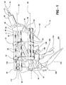
- a second plurality of steering shear elements 34 interconnect the rear bracket 42 and the steering tubes 18.
- the steering shear elements 34 normally prevent movement of the steering tubes 18 relative to the rear bracket 42 , but shear in response to application of the predetermined collapse force to the steering mechanism 14 f or allowing the steering tubes 18 to move through the rear bracket 42 in the same manner as the shear elements associated with the guide bracket 12.
- the rear ends 38 of the steering tubes 18 preferably extend through the rear bracket 40 .
- the brake assembly 106 includes a brake pedal 114.
- a first bracket 116 interconnects the brake pedal 114 and the mounting bracket 112.
- the first bracket 116 includes a slot 118 .
- Adjustment fasteners 120 adjustably mount the brake pedal 114 in the slot 118 for permitting adjustment of the position of the brake pedal 114 relative to the first bracket 116 .
Landscapes
- Engineering & Computer Science (AREA)
- Mechanical Engineering (AREA)
- Transportation (AREA)
- Chemical & Material Sciences (AREA)
- Combustion & Propulsion (AREA)
- Steering Controls (AREA)
Abstract
Description
Claims (25)
- A collapsible steering assembly (10) comprising;a stationary guide bracket (12) for attachment to a vehicle,a steering mechanism (14) having a longitudinal steering mechanism axis (16), anda steering mechanism support (17) including a plurality of guide rods (18) arranged about a common collapse axis (20) in non-parallel relationship to said steering mechanism axis (16) and interconnecting said guide bracket (12) and said steering mechanism (14) and supporting said steering mechanism (14) for axial movement along said collapse axis (20) in response to application of a predetermined collapse force to said steering mechanism (14).
- An assembly as set forth in claim 1 and including a plurality of steering shear elements (34) interconnecting said guide rods (18) and said guide bracket (12) for preventing movement of said steering mechanism (14) relative to said guide bracket (12) and shearable in response to application of the predetermined collapse force on said steering mechanism (14) for allowing said guide rods (18) and said steering mechanism (14) to move relative tosaid guide bracket (12).
- An assembly as set forth in claim 2 wherein said guide bracket (12) supports saidguide rods (18) in fixed relationship to one another.
- An assembly as set forth in claim 3 wherein said guide rods (18) are straight.
- An assembly as set forth in claim 4 wherein each of said guide rods (18) comprises a steering tube extending from a front end (36) to a rear end (38).
- An assembly as set forth in claim 5 wherein each of said steering shear elements (34) comprises a bushing surrounding each steering tube (18) and engaging said guide bracket (12).
- An assembly as set forth in claim 5 wherein said guide bracket (12) includes a front bracket (40) interconnecting said front ends (36) of said steering tubes (18) and a rear bracket (42) supporting said rear ends (38) of said steering tubes (18) and said steering mechanism (14), said front and rear brackets (40) and (42) being spaced from and on opposite sides of said guide bracket (12), whereby said guide bracket (12) is spaced along said steering tubes (18) from and between said front and rear brackets (40) and (42).
- An assembly as set forth in claim 7 wherein said steering tubes (18) comprise four tubes spaced from one another in a quadrangle.
- An assembly as set forth in claim 7 wherein said rear bracket (42) includes a connector (50) for attachment to the vehicle.
- An assembly as set forth in claim 7 wherein said rear ends (38) of said steering tubes (18) extend through said rear bracket (42).
- An assembly as set forth in claim 7 and including a knee bolster (52) for absorbing impact energy during a crash condition, a plurality of bolster guide rods (54) arranged about a second collapse axis (55) and interconnecting said guide bracket (12) and said knee bolster (52) and supporting said knee bolster (52) for axial movement along said second collapse axis (55) in response to application of a second predetermined collapse force to said knee bolster (52).
- An assembly according to claim 11 and including a plurality of bolster shear elements (56) interconnecting said bolster guide rods (54) and said guide bracket (12) for preventing movement of said knee bolster (52) relative to said guide bracket (12) and shearable in response to application of the second predetermined collapse force to said knee bolster (52) for allowing said bolster guide rods (54) and said knee bolster (52) to move relative to saidguide bracket (12).
- An assembly according to claim 12 wherein said guide bracket (12) supports said bolster guide rods (54) in fixed relationship to one another.
- An assembly according to claim 13 wherein said bolster guide rods (54) are straight.
- An assembly according to claim 14 wherein each of said bolster guide rods (54) comprises a tube.
- An assembly as set forth in claim 15 wherein each of said bolster shear elements (56) comprises a bushing surrounding each of said bolster tubes (54) and engaging said guide bracket (12).
- An assembly as set forth in claim 15 wherein said bolster tubes (54) comprise four tubes spaced from one another in a quadrangle.
- An assembly as set forth in claim 15 wherein said bolster tubes (54) have front and rear ends (58) and (60), said knee bolster (52) connected to said front ends (58) of said bolster tubes (54) and said rear bracket (42) supporting said rear ends (60) of said bolster tubes (54),
said knee bolster (52) and said rear bracket (42) being spaced from and on opposite sides of said guide bracket (12). - An assembly as set forth in claim 18 wherein said guide bracket (12) includes an upper block (62) having bores (64) therethrough with said steering tubes (18) extending through said bores (64) and a lower block (66) having bores (68) therethrough with said bolster tubes (54) extending through said bores (68) in said lower block (66).
- An assembly as set forth in claim 19 including a second plurality of steering shear elements (34) interconnecting said rear bracket (42) and said steering tubes (18) for preventing movement of said steering tubes (18) relative to said rear bracket (42) and shearable in response to application of the predetermined collapse force to the steering mechanism (14) for allowing said steering tubes (18) to move through said rear bracket (42).
- An assembly as set forth in claim 15 including an energy absorber system (70) for absorbing energy during movement of said steering mechanism (14) and said knee bolster (52) respectively relative to said guide bracket (12).
- An assembly as set forth in claim 21 wherein said energy absorber system (70) includes a first anvil-strap device (72) interconnecting said steering tubes (18) and said upper block (62).
- An assembly as set forth in claim 22 wherein said bolster tubes (52) are disposed in at least one pair on either side of said steering tubes (18).
- An assembly as set forth in claim 23 wherein said bolster tubes (52) are parallel to said steering tubes (18).
- An assembly as set forth in claim 7 including a pedal assembly (106) pivotally connected to said rear bracket (42) for permitting pivotal movement of said pedal assembly (106) in response to movement of said steering tubes (18) relative to said rear bracket (42).
Applications Claiming Priority (2)
| Application Number | Priority Date | Filing Date | Title |
|---|---|---|---|
| US767988 | 2004-01-29 | ||
| US10/767,988 US7063354B2 (en) | 2003-01-31 | 2004-01-29 | Linear tracking column module |
Publications (3)
| Publication Number | Publication Date |
|---|---|
| EP1566323A2 true EP1566323A2 (en) | 2005-08-24 |
| EP1566323A3 EP1566323A3 (en) | 2007-07-18 |
| EP1566323B1 EP1566323B1 (en) | 2009-03-25 |
Family
ID=34711824
Family Applications (1)
| Application Number | Title | Priority Date | Filing Date |
|---|---|---|---|
| EP05075130A Expired - Lifetime EP1566323B1 (en) | 2004-01-29 | 2005-01-19 | Linear tracking column module |
Country Status (4)
| Country | Link |
|---|---|
| US (1) | US7063354B2 (en) |
| EP (1) | EP1566323B1 (en) |
| AT (1) | ATE426541T1 (en) |
| DE (1) | DE602005013439D1 (en) |
Families Citing this family (7)
| Publication number | Priority date | Publication date | Assignee | Title |
|---|---|---|---|---|
| US7128342B2 (en) * | 2003-01-31 | 2006-10-31 | Delphi Technologies, Inc. | Linear tracking knee bolster assembly |
| US7188866B2 (en) * | 2004-02-26 | 2007-03-13 | Delphi Technologies, Inc | Steering column assembly and method of fabricating the same |
| US7942446B2 (en) * | 2004-04-30 | 2011-05-17 | Nexteer (Beijing) Technology Co., Ltd. | Horizontal hybrid collapsing steering column |
| US7425020B2 (en) * | 2006-04-25 | 2008-09-16 | Mats Lindkvist | Steering wheel suspension system |
| JP5865805B2 (en) * | 2012-09-05 | 2016-02-17 | Kyb株式会社 | Steering device |
| US10509120B2 (en) * | 2017-02-16 | 2019-12-17 | GM Global Technology Operations LLC | Lidar-radar relative pose calibration |
| US12583507B1 (en) * | 2024-11-21 | 2026-03-24 | Fca Us Llc | Decoupled driver controls module for vehicle |
Family Cites Families (34)
| Publication number | Priority date | Publication date | Assignee | Title |
|---|---|---|---|---|
| US3964578A (en) * | 1975-08-27 | 1976-06-22 | General Motors Corporation | Energy absorber |
| US4738469A (en) * | 1985-12-23 | 1988-04-19 | Mazda Motor Corporation | Structural arrangements for supporting steering devices |
| US4875385A (en) * | 1986-08-18 | 1989-10-24 | Sitrin Gabriel M | Control pedal apparatus for a motor vehicle |
| US4949590A (en) * | 1988-02-17 | 1990-08-21 | Automotive Products Plc | Hydraulic cylinder assembly |
| EP0353958B1 (en) * | 1988-07-28 | 1993-09-29 | Fuji Kiko Company Limited | Position adjustable pedal assembly |
| JP2521802B2 (en) * | 1988-12-28 | 1996-08-07 | 日産自動車株式会社 | Vehicle near protector structure |
| US5086663A (en) * | 1989-07-28 | 1992-02-11 | Fuji Kiko Company, Limited | Adjustable pedal |
| US5259646A (en) * | 1992-03-20 | 1993-11-09 | Nissan Research & Development, Inc. | Multifunction one-piece bracket to support a steering column assemby and brake pedal support bracket in an automobile |
| US5181435A (en) * | 1992-03-30 | 1993-01-26 | Chrysler Corp | Steering column guide assembly |
| JPH08113148A (en) * | 1994-10-19 | 1996-05-07 | Honda Motor Co Ltd | Vehicle steering column support structure |
| DE19502226C1 (en) * | 1995-01-25 | 1996-05-09 | Daimler Benz Ag | Impact protection for interior of vehicles |
| DE19522398C1 (en) * | 1995-06-23 | 1996-12-19 | Daimler Benz Ag | Safety arrangement in the footwell of a motor vehicle |
| SE507008C2 (en) * | 1996-09-16 | 1998-03-16 | Lars Sundholm | Procedure and system for reducing personal injury in the event of a frontal collision |
| SE507771C2 (en) * | 1996-11-21 | 1998-07-13 | Volvo Ab | Device and method of protection of occupants in vehicles |
| SE510856C2 (en) * | 1997-06-23 | 1999-06-28 | Volvo Ab | Power absorbing device for protection of occupants in vehicles |
| DE19747423C1 (en) * | 1997-10-27 | 1999-04-29 | Bsrs Restraint Syst Gmbh | Knee protector for passenger vehicle occupant |
| DE19749970A1 (en) * | 1997-11-05 | 1999-05-12 | Petri Ag | Occupant safety device for the driver side of a motor vehicle |
| SE518099C2 (en) * | 1997-11-21 | 2002-08-27 | Claes Johansson Automotive Ab | Adjustable pedal rack for a vehicle |
| JP3449206B2 (en) * | 1998-02-04 | 2003-09-22 | トヨタ自動車株式会社 | Vehicle pedal displacement control structure |
| FR2781189B1 (en) * | 1998-07-16 | 2000-09-15 | Allibert Ind | DEVICE FOR PROTECTING A VEHICLE DRIVER IN THE EVENT OF AN IMPACT THEREOF |
| US6474687B2 (en) * | 1999-04-15 | 2002-11-05 | Visteon Global Technologies, Inc. | One-piece knee bolster |
| US6152488A (en) * | 1999-06-16 | 2000-11-28 | Ford Global Technologies, Inc. | Steering column with variable collapse force |
| US6173625B1 (en) * | 1999-12-14 | 2001-01-16 | Teleflex Incorporated | Adjustable multi-pedal assembly |
| FR2805512B1 (en) * | 2000-02-24 | 2002-05-03 | Nacam | DEVICE FOR LINEAR GUIDANCE OF A STEERING COLUMN |
| US6619155B2 (en) * | 2000-05-15 | 2003-09-16 | Grand Haven Stamped Products, Division Of Jsj Corporation | Adjustable pedal apparatus |
| GB2368561B (en) * | 2000-11-01 | 2003-08-13 | Visteon Global Tech Inc | Motor vehicle steering column support assembly |
| US6581966B2 (en) * | 2001-01-05 | 2003-06-24 | Ford Global Technologies, Inc. | Twin axis steering wheel system |
| JP2002308116A (en) * | 2001-04-12 | 2002-10-23 | Nissan Motor Co Ltd | Steering column support device |
| US6641166B2 (en) * | 2001-05-25 | 2003-11-04 | General Motors Corporation | Extendable and retractable knee bolster system |
| US6609727B2 (en) * | 2001-08-06 | 2003-08-26 | General Motors Corporation | Energy absorbing knee bolster assembly |
| KR100405559B1 (en) * | 2001-09-20 | 2003-11-14 | 현대자동차주식회사 | a preventing structure for being pushed of brake pedal of vehicles |
| US6685224B2 (en) * | 2001-12-27 | 2004-02-03 | Daimlerchrysler Corporation | Tilt steering column |
| US7048306B2 (en) * | 2002-09-05 | 2006-05-23 | Delphi Technologies, Inc. | Steering column with tubular structure |
| US7188866B2 (en) * | 2004-02-26 | 2007-03-13 | Delphi Technologies, Inc | Steering column assembly and method of fabricating the same |
-
2004
- 2004-01-29 US US10/767,988 patent/US7063354B2/en not_active Expired - Fee Related
-
2005
- 2005-01-19 EP EP05075130A patent/EP1566323B1/en not_active Expired - Lifetime
- 2005-01-19 DE DE602005013439T patent/DE602005013439D1/en not_active Expired - Fee Related
- 2005-01-19 AT AT05075130T patent/ATE426541T1/en not_active IP Right Cessation
Also Published As
| Publication number | Publication date |
|---|---|
| EP1566323B1 (en) | 2009-03-25 |
| ATE426541T1 (en) | 2009-04-15 |
| DE602005013439D1 (en) | 2009-05-07 |
| US7063354B2 (en) | 2006-06-20 |
| EP1566323A3 (en) | 2007-07-18 |
| US20040239090A1 (en) | 2004-12-02 |
Similar Documents
| Publication | Publication Date | Title |
|---|---|---|
| US6595079B2 (en) | Collapsible steering column assembly for a vehicle | |
| EP1225072B1 (en) | Power unit layout structure | |
| US7264274B2 (en) | Tuneable energy absorbing mounting structure for steering column | |
| US20070228717A1 (en) | Steering column apparatus for vehicle | |
| US7185918B2 (en) | Linear tracking column module with pedal assembly | |
| US7384070B2 (en) | Shock absorbing steering column device for vehicle | |
| JP2000148271A (en) | Fitting assembly for adjustable pedal | |
| EP1566323B1 (en) | Linear tracking column module | |
| EP1559618B1 (en) | Linear tracking knee bolster assembly | |
| US5417452A (en) | Steering column energy absorbing assembly | |
| US5209135A (en) | Impact absorbing type steering column device | |
| JP2004082868A (en) | Shock absorbing steering column device | |
| EP1179461B1 (en) | Automotive pedal support structure and automotive vehicle provided therewith | |
| KR100201728B1 (en) | Energy absorption system | |
| CN111727148B (en) | Steering column for a motor vehicle | |
| JP4604425B2 (en) | Steering column mounting structure | |
| US6820899B2 (en) | Collapsible steering column assembly for a vehicle | |
| JP2005343331A (en) | Vehicle steering device | |
| EP0463501A1 (en) | Collapsible, energy absorbing steering column support system | |
| JP2002308117A (en) | Shock absorbing type steering device | |
| JP2647175B2 (en) | Operation lever of steering tilt device | |
| KR100489079B1 (en) | Brake Pedal for Vehicle | |
| KR100231529B1 (en) | Mounting structure for shock absorbing steering devices | |
| JP3951236B2 (en) | Pedal support structure for vehicles | |
| JPH02102807A (en) | Steering tilt device with shock absorber |
Legal Events
| Date | Code | Title | Description |
|---|---|---|---|
| PUAI | Public reference made under article 153(3) epc to a published international application that has entered the european phase |
Free format text: ORIGINAL CODE: 0009012 |
|
| AK | Designated contracting states |
Kind code of ref document: A2 Designated state(s): AT BE BG CH CY CZ DE DK EE ES FI FR GB GR HU IE IS IT LI LT LU MC NL PL PT RO SE SI SK TR |
|
| AX | Request for extension of the european patent |
Extension state: AL BA HR LV MK YU |
|
| PUAL | Search report despatched |
Free format text: ORIGINAL CODE: 0009013 |
|
| AK | Designated contracting states |
Kind code of ref document: A3 Designated state(s): AT BE BG CH CY CZ DE DK EE ES FI FR GB GR HU IE IS IT LI LT LU MC NL PL PT RO SE SI SK TR |
|
| AX | Request for extension of the european patent |
Extension state: AL BA HR LV MK YU |
|
| 17P | Request for examination filed |
Effective date: 20080118 |
|
| AKX | Designation fees paid |
Designated state(s): AT BE BG CH CY CZ DE DK EE ES FI FR GB GR HU IE IS IT LI LT LU MC NL PL PT RO SE SI SK TR |
|
| 17Q | First examination report despatched |
Effective date: 20080310 |
|
| GRAP | Despatch of communication of intention to grant a patent |
Free format text: ORIGINAL CODE: EPIDOSNIGR1 |
|
| GRAS | Grant fee paid |
Free format text: ORIGINAL CODE: EPIDOSNIGR3 |
|
| GRAA | (expected) grant |
Free format text: ORIGINAL CODE: 0009210 |
|
| AK | Designated contracting states |
Kind code of ref document: B1 Designated state(s): AT BE BG CH CY CZ DE DK EE ES FI FR GB GR HU IE IS IT LI LT LU MC NL PL PT RO SE SI SK TR |
|
| REG | Reference to a national code |
Ref country code: GB Ref legal event code: FG4D |
|
| REG | Reference to a national code |
Ref country code: CH Ref legal event code: EP |
|
| REG | Reference to a national code |
Ref country code: IE Ref legal event code: FG4D |
|
| REF | Corresponds to: |
Ref document number: 602005013439 Country of ref document: DE Date of ref document: 20090507 Kind code of ref document: P |
|
| PG25 | Lapsed in a contracting state [announced via postgrant information from national office to epo] |
Ref country code: SI Free format text: LAPSE BECAUSE OF FAILURE TO SUBMIT A TRANSLATION OF THE DESCRIPTION OR TO PAY THE FEE WITHIN THE PRESCRIBED TIME-LIMIT Effective date: 20090325 Ref country code: FI Free format text: LAPSE BECAUSE OF FAILURE TO SUBMIT A TRANSLATION OF THE DESCRIPTION OR TO PAY THE FEE WITHIN THE PRESCRIBED TIME-LIMIT Effective date: 20090325 Ref country code: LT Free format text: LAPSE BECAUSE OF FAILURE TO SUBMIT A TRANSLATION OF THE DESCRIPTION OR TO PAY THE FEE WITHIN THE PRESCRIBED TIME-LIMIT Effective date: 20090325 |
|
| PG25 | Lapsed in a contracting state [announced via postgrant information from national office to epo] |
Ref country code: PL Free format text: LAPSE BECAUSE OF FAILURE TO SUBMIT A TRANSLATION OF THE DESCRIPTION OR TO PAY THE FEE WITHIN THE PRESCRIBED TIME-LIMIT Effective date: 20090325 Ref country code: SE Free format text: LAPSE BECAUSE OF FAILURE TO SUBMIT A TRANSLATION OF THE DESCRIPTION OR TO PAY THE FEE WITHIN THE PRESCRIBED TIME-LIMIT Effective date: 20090625 Ref country code: AT Free format text: LAPSE BECAUSE OF FAILURE TO SUBMIT A TRANSLATION OF THE DESCRIPTION OR TO PAY THE FEE WITHIN THE PRESCRIBED TIME-LIMIT Effective date: 20090325 |
|
| NLV1 | Nl: lapsed or annulled due to failure to fulfill the requirements of art. 29p and 29m of the patents act | ||
| PG25 | Lapsed in a contracting state [announced via postgrant information from national office to epo] |
Ref country code: BE Free format text: LAPSE BECAUSE OF FAILURE TO SUBMIT A TRANSLATION OF THE DESCRIPTION OR TO PAY THE FEE WITHIN THE PRESCRIBED TIME-LIMIT Effective date: 20090325 |
|
| PG25 | Lapsed in a contracting state [announced via postgrant information from national office to epo] |
Ref country code: PT Free format text: LAPSE BECAUSE OF FAILURE TO SUBMIT A TRANSLATION OF THE DESCRIPTION OR TO PAY THE FEE WITHIN THE PRESCRIBED TIME-LIMIT Effective date: 20090901 Ref country code: CZ Free format text: LAPSE BECAUSE OF FAILURE TO SUBMIT A TRANSLATION OF THE DESCRIPTION OR TO PAY THE FEE WITHIN THE PRESCRIBED TIME-LIMIT Effective date: 20090325 Ref country code: EE Free format text: LAPSE BECAUSE OF FAILURE TO SUBMIT A TRANSLATION OF THE DESCRIPTION OR TO PAY THE FEE WITHIN THE PRESCRIBED TIME-LIMIT Effective date: 20090325 Ref country code: ES Free format text: LAPSE BECAUSE OF FAILURE TO SUBMIT A TRANSLATION OF THE DESCRIPTION OR TO PAY THE FEE WITHIN THE PRESCRIBED TIME-LIMIT Effective date: 20090706 |
|
| PG25 | Lapsed in a contracting state [announced via postgrant information from national office to epo] |
Ref country code: IS Free format text: LAPSE BECAUSE OF FAILURE TO SUBMIT A TRANSLATION OF THE DESCRIPTION OR TO PAY THE FEE WITHIN THE PRESCRIBED TIME-LIMIT Effective date: 20090725 Ref country code: NL Free format text: LAPSE BECAUSE OF FAILURE TO SUBMIT A TRANSLATION OF THE DESCRIPTION OR TO PAY THE FEE WITHIN THE PRESCRIBED TIME-LIMIT Effective date: 20090325 Ref country code: SK Free format text: LAPSE BECAUSE OF FAILURE TO SUBMIT A TRANSLATION OF THE DESCRIPTION OR TO PAY THE FEE WITHIN THE PRESCRIBED TIME-LIMIT Effective date: 20090325 Ref country code: RO Free format text: LAPSE BECAUSE OF FAILURE TO SUBMIT A TRANSLATION OF THE DESCRIPTION OR TO PAY THE FEE WITHIN THE PRESCRIBED TIME-LIMIT Effective date: 20090325 |
|
| PG25 | Lapsed in a contracting state [announced via postgrant information from national office to epo] |
Ref country code: DK Free format text: LAPSE BECAUSE OF FAILURE TO SUBMIT A TRANSLATION OF THE DESCRIPTION OR TO PAY THE FEE WITHIN THE PRESCRIBED TIME-LIMIT Effective date: 20090325 Ref country code: BG Free format text: LAPSE BECAUSE OF FAILURE TO SUBMIT A TRANSLATION OF THE DESCRIPTION OR TO PAY THE FEE WITHIN THE PRESCRIBED TIME-LIMIT Effective date: 20090625 |
|
| PLBE | No opposition filed within time limit |
Free format text: ORIGINAL CODE: 0009261 |
|
| STAA | Information on the status of an ep patent application or granted ep patent |
Free format text: STATUS: NO OPPOSITION FILED WITHIN TIME LIMIT |
|
| 26N | No opposition filed |
Effective date: 20091229 |
|
| REG | Reference to a national code |
Ref country code: FR Ref legal event code: TP |
|
| PG25 | Lapsed in a contracting state [announced via postgrant information from national office to epo] |
Ref country code: MC Free format text: LAPSE BECAUSE OF NON-PAYMENT OF DUE FEES Effective date: 20100131 |
|
| REG | Reference to a national code |
Ref country code: CH Ref legal event code: PL |
|
| GBPC | Gb: european patent ceased through non-payment of renewal fee |
Effective date: 20100119 |
|
| REG | Reference to a national code |
Ref country code: FR Ref legal event code: ST Effective date: 20100930 |
|
| PG25 | Lapsed in a contracting state [announced via postgrant information from national office to epo] |
Ref country code: GR Free format text: LAPSE BECAUSE OF FAILURE TO SUBMIT A TRANSLATION OF THE DESCRIPTION OR TO PAY THE FEE WITHIN THE PRESCRIBED TIME-LIMIT Effective date: 20090626 Ref country code: CH Free format text: LAPSE BECAUSE OF NON-PAYMENT OF DUE FEES Effective date: 20100131 Ref country code: LI Free format text: LAPSE BECAUSE OF NON-PAYMENT OF DUE FEES Effective date: 20100131 Ref country code: FR Free format text: LAPSE BECAUSE OF NON-PAYMENT OF DUE FEES Effective date: 20100201 |
|
| PG25 | Lapsed in a contracting state [announced via postgrant information from national office to epo] |
Ref country code: DE Free format text: LAPSE BECAUSE OF NON-PAYMENT OF DUE FEES Effective date: 20100803 |
|
| PG25 | Lapsed in a contracting state [announced via postgrant information from national office to epo] |
Ref country code: GB Free format text: LAPSE BECAUSE OF NON-PAYMENT OF DUE FEES Effective date: 20100119 |
|
| PG25 | Lapsed in a contracting state [announced via postgrant information from national office to epo] |
Ref country code: IE Free format text: LAPSE BECAUSE OF NON-PAYMENT OF DUE FEES Effective date: 20100119 |
|
| PG25 | Lapsed in a contracting state [announced via postgrant information from national office to epo] |
Ref country code: IT Free format text: LAPSE BECAUSE OF FAILURE TO SUBMIT A TRANSLATION OF THE DESCRIPTION OR TO PAY THE FEE WITHIN THE PRESCRIBED TIME-LIMIT Effective date: 20090325 |
|
| REG | Reference to a national code |
Ref country code: DE Ref legal event code: R081 Ref document number: 602005013439 Country of ref document: DE Owner name: GM GLOBAL TECHNOLOGY OPERATIONS, INC., US Free format text: FORMER OWNER: DELPHI TECHNOLOGIES, INC., TROY, US Effective date: 20110412 |
|
| PG25 | Lapsed in a contracting state [announced via postgrant information from national office to epo] |
Ref country code: CY Free format text: LAPSE BECAUSE OF FAILURE TO SUBMIT A TRANSLATION OF THE DESCRIPTION OR TO PAY THE FEE WITHIN THE PRESCRIBED TIME-LIMIT Effective date: 20090325 |
|
| PG25 | Lapsed in a contracting state [announced via postgrant information from national office to epo] |
Ref country code: LU Free format text: LAPSE BECAUSE OF NON-PAYMENT OF DUE FEES Effective date: 20100119 Ref country code: HU Free format text: LAPSE BECAUSE OF FAILURE TO SUBMIT A TRANSLATION OF THE DESCRIPTION OR TO PAY THE FEE WITHIN THE PRESCRIBED TIME-LIMIT Effective date: 20090926 |
|
| PG25 | Lapsed in a contracting state [announced via postgrant information from national office to epo] |
Ref country code: TR Free format text: LAPSE BECAUSE OF FAILURE TO SUBMIT A TRANSLATION OF THE DESCRIPTION OR TO PAY THE FEE WITHIN THE PRESCRIBED TIME-LIMIT Effective date: 20090325 |