EP1566292A1 - Pneumatic tire - Google Patents
Pneumatic tire Download PDFInfo
- Publication number
- EP1566292A1 EP1566292A1 EP04106586A EP04106586A EP1566292A1 EP 1566292 A1 EP1566292 A1 EP 1566292A1 EP 04106586 A EP04106586 A EP 04106586A EP 04106586 A EP04106586 A EP 04106586A EP 1566292 A1 EP1566292 A1 EP 1566292A1
- Authority
- EP
- European Patent Office
- Prior art keywords
- profile
- profile element
- pneumatic
- circumferential direction
- sipe
- Prior art date
- Legal status (The legal status is an assumption and is not a legal conclusion. Google has not performed a legal analysis and makes no representation as to the accuracy of the status listed.)
- Withdrawn
Links
Images


Classifications
-
- B—PERFORMING OPERATIONS; TRANSPORTING
- B60—VEHICLES IN GENERAL
- B60C—VEHICLE TYRES; TYRE INFLATION; TYRE CHANGING; CONNECTING VALVES TO INFLATABLE ELASTIC BODIES IN GENERAL; DEVICES OR ARRANGEMENTS RELATED TO TYRES
- B60C11/00—Tyre tread bands; Tread patterns; Anti-skid inserts
- B60C11/03—Tread patterns
- B60C11/11—Tread patterns in which the raised area of the pattern consists only of isolated elements, e.g. blocks
-
- B—PERFORMING OPERATIONS; TRANSPORTING
- B60—VEHICLES IN GENERAL
- B60C—VEHICLE TYRES; TYRE INFLATION; TYRE CHANGING; CONNECTING VALVES TO INFLATABLE ELASTIC BODIES IN GENERAL; DEVICES OR ARRANGEMENTS RELATED TO TYRES
- B60C11/00—Tyre tread bands; Tread patterns; Anti-skid inserts
- B60C11/03—Tread patterns
- B60C11/032—Patterns comprising isolated recesses
-
- B—PERFORMING OPERATIONS; TRANSPORTING
- B60—VEHICLES IN GENERAL
- B60C—VEHICLE TYRES; TYRE INFLATION; TYRE CHANGING; CONNECTING VALVES TO INFLATABLE ELASTIC BODIES IN GENERAL; DEVICES OR ARRANGEMENTS RELATED TO TYRES
- B60C11/00—Tyre tread bands; Tread patterns; Anti-skid inserts
- B60C11/03—Tread patterns
- B60C11/12—Tread patterns characterised by the use of narrow slits or incisions, e.g. sipes
-
- B—PERFORMING OPERATIONS; TRANSPORTING
- B60—VEHICLES IN GENERAL
- B60C—VEHICLE TYRES; TYRE INFLATION; TYRE CHANGING; CONNECTING VALVES TO INFLATABLE ELASTIC BODIES IN GENERAL; DEVICES OR ARRANGEMENTS RELATED TO TYRES
- B60C11/00—Tyre tread bands; Tread patterns; Anti-skid inserts
- B60C11/03—Tread patterns
- B60C11/13—Tread patterns characterised by the groove cross-section, e.g. for buttressing or preventing stone-trapping
Definitions
- the invention relates to a pneumatic vehicle tire with a tread profile with by Profile grooves laterally limited profile block elements, wherein the profile block elements after radially outward by a contact surface for the production of the frictional contact to Road surface and laterally with profiled element edges forming surfaces limited are, each from the groove bottom of the limiting tread groove radially outward extend to the contact surface.
- the invention is based on the object in a pneumatic vehicle tire with a Tread profile with profile block elements laterally limited by tread grooves, wherein the tread block elements radially outward through a contact surface for the production the frictional contact with the road surface and laterally with profiled element edges forming Surfaces are limited, each resulting from the groove bottom of the limiting Tread groove extending radially outward to the contact surface, to allow for forces be transferred better between profile element and road during dynamic processes can.
- the object is achieved by the formation of a pneumatic vehicle tire with a tread profile with laterally limited by tread grooves Profile block elements, wherein the profile block elements radially outward by a Contact surface for producing the frictional contact with the road surface and laterally with Profilelementflanken forming surfaces are limited, each consisting of the Groove bottom of the limiting profile groove radially outward to the contact surface extend, solved according to the features of claim 1, wherein in at least one a profile element flank forming surface is a sipe formed in the the profile element flank forming surfaces completely closed with Rubber material is enveloped, so that in dependence of acting in the radial direction Tensile and / or compressive stresses in the surface of the profiled element forming the surface radial extension of the profile element flank under opening and / or closing the Fine incision is changeable.
- this Fine incision in the operating state of the assembled pneumatic vehicle tire in the in Circumferential direction of the pneumatic vehicle tire when the vehicle is traveling forwards Profile element limiting in the circumferential direction of the pneumatic vehicle tire Profile element flank is formed this can be a targeted homogenization of Force transmission when the vehicle accelerates in the forward direction and thus improved traction can be achieved.
- this Fine incision in the operating state of the assembled pneumatic vehicle tire in the in Circumferential direction of the pneumatic vehicle tire when the vehicle is traveling forwards Profile element limiting in the circumferential direction of the pneumatic vehicle tire Profile element flank is formed this can be a targeted homogenization of Force application when braking the vehicle when moving in the forward direction and thus an improved braking effect can be achieved.
- a pneumatic vehicle tire in which a core 2 with Kemprofil 4 a first carcass ply 8 of known type outside of one air-impermeable inner layer 6 over the right shoulder area and the zenith plane to the left shoulder area and the left core 2 with Kemprofil 4 ranges to which they are in conventionally laid.
- a second carcass ply 9 of known type which is also from the in Fig.1 shown on the right side of the tire extends to the left side.
- the radial direction R of the pneumatic vehicle tire is also with Indicated arrow, the direction of the arrow from radially inward to radially outward has.
- the circumferential direction U of the pneumatic vehicle tire with arrow indicated, wherein the arrow direction, the direction of rotation of the pneumatic vehicle tire in on Vehicle-mounted operating state indicates when driving forward.
- the tread 1 with a tire tread is formed, which in the axial direction A, starting from the left tire shoulder to to the right tire shoulder arranged one behind the other with a circumferential direction U aligned profile block row 19, which extends into the left shoulder area, with an in Circumferential direction U-oriented profile block row 20, with a central in Circumferentially U aligned profile block row 21, with a circumferential direction U aligned profile block row 22 and aligned with a circumferentially U Profile block row 24, which extends into the right shoulder area is formed.
- the Profile block row 19 is of a plurality of circumferentially U of the tire formed successively arranged profile block elements 35 of known type, the are separated from each other by a transverse groove 25 of known type.
- the Profile block row 20 is of a plurality of circumferentially U of the tire formed successively arranged profile block elements 36 of known type, the are separated from each other by a transverse groove 26 of known type.
- the Profile block row 21 is of a plurality of circumferentially U in a row arranged profile block elements 37 known type formed, each of which are separated by a transverse groove 27 of known type.
- the profile block row 22 is of a Variety of circumferentially U successively arranged profile block elements 38th formed of known type, each of which by a transverse groove 28 of known type are separated.
- the profile block row 24 is made of a plurality of circumferentially U formed successively arranged profile block elements 39 of known type, the are separated from each other by a transverse groove 29 of known type.
- the Profile block rows 19 and 20 are in the axial direction A of the pneumatic vehicle tire by a of the tire extends, separated from each other.
- the profile block rows 20 and 21 are in in Circumferential direction U extending circumferential groove 16 extending over the entire circumference axial direction A of the pneumatic vehicle tire by a circumferential direction U of the tire extending and extending over the entire circumference circumferential groove 12 known Kind of separated.
- the profile block rows 21 and 22 are in the axial direction A of Tire by running in the circumferential direction U of the tire and over the entire Circumference of the tire extended circumferential groove 17 known type separated from each other.
- the Profile block row 22 and the profile block row 24 are in the axial direction A by a in Circumferential direction U of the tire extending and over the entire circumference of the tire extended circumferential groove 18 of known type separated from each other.
- the inventive design of the profile block edges is the example a profile block element 37 of the profile block row 21 on the basis of several Embodiments explained.
- the tread block elements 37 are each laterally in the axial direction to the circumferential grooves 12 and 17 formed with lateral profile block edges 33 and 32, at the in the Circumferential direction U of the pneumatic vehicle tire when driving forward of the vehicle with assembled pneumatic vehicle tire with a profile block element of the limiting front tread element flank 30 and with the tread block element to the rear limiting profile block element edge 31 formed.
- the two Profile block element flanks 30 and 31 bound the tread block element 37 to one each Transverse groove 27.
- the profile block element flanks 30, 31, 32, 33 each extend radially out of the groove bottom of the associated groove 27, 27, 17, 12 outwardly to the Profile block element radially outwardly bounding contact surface 34, with the Profile block element when passing through the footprint in frictional contact with the respective Road surface stands.
- a radial sipe 40 formed radially inside ends above the groove bottom and radially outward in a radial position radially terminates within the contact surface 34.
- the sipe 40 is in the profile flank 30th completely and closed enveloped by rubber material.
- the depth T of the sipe 4, which indicates the depth extent of the cut in the tread block element 37, is for example, chosen to be 1/3 to 2/3 of the total extension B of the Profile block element 37 in the circumferential direction in position of the sipe 40 in the Profile element edge 30 is.
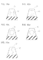
- Fig. 6a is shown, as in conventional tires, a tread block element, the Braking a equipped with the vehicle pneumatic tire vehicle from forward drive below Deformation of the profile block element 37 without additional radial length compensation of front or rear tread element flank 30 or 31 by wave-like Disturbances of the contact surface 34 occur. The contact with the road surface 41 is thereby reduced.
- Fig. 6b shows the tread block element 37 of Figures 3 to 5, wherein when braking the Vehicle from the forward drive by opening the radially extending fine section 40 a radial shortening of the front profile block element edge 30 takes place. The uprisings the contact surface 34 are reduced. The contact with the road surface 41 is uniform.
- FIGS. 7 to 10 show an embodiment in which, during rotation of the Pneumatic vehicle tire when driving forward of the vehicle to a profile block element 37 in Circumferential direction U to the rear limiting profile block element edge 31 a transverse to Radial direction extending sipe 42 is formed, which extends to both extends axially sides and still within the profile block element laterally delimiting Profile block edges 32, 33 ends.
- the sipe 42 is thus in the Profile block element flank 31 closed surrounded by rubber material.
- Regarding its depth extension T of the fine incision 42 applies to the sip 41 of the Embodiment of Figures 3 to 6 said.
- As shown in Fig. 10 is in Braking the vehicle from the forward drive the profile block element edge 31 under radial spreading of the sipe 42 radially elongated.
- the contact surface 34 is evenly evened and the frictional contact with the road surface 41 evened.
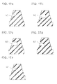
- FIGS. 11 and 12 show alternative embodiments of the sipe of FIG 3, wherein the sipe 40 of Fig. 11 wave-shaped and the sipe 40th of Fig. 12 is serrated.
- FIGS. 13 and 14 respectively show alternative embodiments of the invention Fine incision 42 of Fig. 7, wherein the sipe 42 of FIG. 13 wave-shaped and the sipe 42 of Fig. 14 is serrated.
- Figures 15, 16a, 16b, 16c, 16d and 16e show further alternative embodiments the sipes, which have both section areas, in the radial direction extend as well as section areas which extend transversely to the radial direction.
- Figure 15 shows a sipe with an oval or elliptical course, the Main directions of extension in the radial direction and in the direction transverse to the radial is aligned.
- Fig. 16a and Fig. 16b show H-shaped sipes.
- Fig. 16c shows a square sipe, Fig16d a circular-shaped and Fig. 16e a jagged with transverse to the radial direction terminations.
- Embodiments can - even if only as a fine incision 40 at the front Profile block element flank 30 or as a sipe 42 at the rear Profilblockelementflanke 31 shown - each as a sipe 40 in the front profile block element edge 30 - as shown in the embodiment of Fig. 3 - or as a sipe 42 in the rear profile block element edge 31 - as in Fig. 7 shown - are used.
- the extending in the radial direction Fine incision component allows opening of this sipe component across to the radial direction at radial pressure loading of the profile block edge, wherein the transverse remains closed to the radial fine sipe component. This allows the insert on the front profile block element flank 30, as shown in Figs. 3,4,5 and 6b is shown.
- the sipe component running transversely to the radial allows for a radial opening of this transverse to the radial Fine incision component profile under radial tensile load, wherein in radial Direction running fine sipe components remain closed. This makes possible the use of these fine incisions as sip 41 in the rear Profile block element flank 32, as shown in Fig. 7 to 10.
- FIGS. 17a, 17b, 17c, 17d and 17e show the example of that shown in FIG radial fine incision 30 different alternatives of the contour of the section inside the tread block element.
- the contour of the cut can be for example - as shown in Fig. 17b - at its inner end square or - as in Fig. 17c shown - are formed rounded.
- the cross section can - as in Fig. 17b - rectangular or - as shown in FIGS. 17a, 17d and 17e - be formed triangular.
- the triangular cross-sectional contour of the slot can - as in Fig. 17e shown - as an equiangular triangle or - as in Figures 17a and 17d shown - be designed as a right triangle.
- the tread block elements are either at their rear Profile block element flank 31 with radial fine incisions 40 or with fine incisions 40 formed with radial component, which in acceleration of the pneumatic vehicle tire in Forward direction of the vehicle when touching the contact surface 34 with a Road surface 41 due to radial compressive forces under opening of the Fine incision 40 transverse to the radial direction a shortening of the rear Profile block element flank 31 effects, and / or on the front profile block element flank 30 with sipes 42 extending transverse to the radial direction or with Fine sipes 42 with sipe components transverse to the radial Direction trained in acceleration of the pneumatic vehicle tire in Forward direction of the vehicle when touching the contact surface 34 with a Road surface 41 due to radial tensile forces opening the sipe in radial direction and thus an elongation of the front profile block element edge 30th causes, whereby a uniform frictional contact between the contact surface 34 and Road surface 41 is achieved.
- both radial components and across the have radially aligned components of their cutting process - as they For example, in Figs. 15 and 16a, b, c, d, e are shown - Braking from forward drive as well as when accelerating when driving forward and when Brakes from reverse drive as well as during acceleration in reverse drive uniform frictional contact between contact surface 34 and road surface 41 be achieved.
Abstract
Description
Die Erfindung betrifft einen Fahrzeugluftreifen mit einem Laufflächenprofil mit von durch Profilrillen seitlich begrenzten Profilblockelementen, wobei die Profilblockelemente nach radial außen durch eine Kontaktfläche zur Herstellung des Reibkontaktes zur Straßenoberfläche und seitlich mit Profilelementflanken bildenden Oberflächen begrenzt sind, die sich jeweils aus dem Rillengrund der begrenzenden Profilrille radial nach außen bis zur Kontaktfläche erstrecken.The invention relates to a pneumatic vehicle tire with a tread profile with by Profile grooves laterally limited profile block elements, wherein the profile block elements after radially outward by a contact surface for the production of the frictional contact to Road surface and laterally with profiled element edges forming surfaces limited are, each from the groove bottom of the limiting tread groove radially outward extend to the contact surface.
Bei dynamischen Belastungen der Profilblockelemente im Latsch, wie sie beispielsweise beim Beschleunigen oder beim Bremsen auftreten, kommt es in Abhängigkeit von der Belastung zu unterschiedlichen Deformationen der einander in Belastungsrichtung gegenüberliegenden Profilflanken des jeweiligen Profilblockelements. Dies führt zu Deformationen mit unerwünschten Erhebungen und Vertiefungen der nach radial außen zur Herstellung des Reibkontaktes zur Straßenoberfläche ausgebildeten Kontaktfläche des jeweiligen Profilblockelements, wodurch die für die dynamische Krafteinleitung zwischen Straßenoberfläche und der ausgebildeten Kontaktfläche effektiv zur Verfugung stehende Fläche lediglich auf kleine Teilbereiche der ausgebildeten Kontaktfläche zur großen Krafteinleitung und andere Bereiche zur Einleitung - wenn überhaupt - nur geringer Kraftanteile beschränkt wird. Dies beschränkt die bei dynamischen Vorgängen von den Profilelementen übertragbaren Kräfte.For dynamic loads of the profile block elements in the laces, as for example occur during acceleration or braking, it depends on the Load to different deformations of each other in the loading direction opposite profile edges of the respective profile block element. this leads to Deformations with unwanted elevations and depressions of the radially outward for the preparation of the frictional contact to the road surface formed contact surface of respective tread block element, whereby the dynamic force transmission between Road surface and the trained contact surface effectively available Area only on small portions of the formed contact surface to the large Force introduction and other initiation areas, if any, are less Power shares is limited. This limits the dynamic processes of the Profile elements transferable forces.
Der Erfindung liegt die Aufgabe zugrunde, bei einem Fahrzeugluftreifen mit einem Laufflächenprofil mit von durch Profilrillen seitlich begrenzten Profilblockelementen, wobei die Profilblockelemente nach radial außen durch eine Kontaktfläche zur Herstellung des Reibkontaktes zur Straßenoberfläche und seitlich mit Profilelementflanken bildenden Oberflächen begrenzt sind, die sich jeweils aus dem Rillengrund der begrenzenden Profilrille radial nach außen bis zur Kontaktfläche erstrecken, zu ermöglichen, dass Kräfte bei dynamischen Vorgängen besser zwischen Profilelement und Straße übertragen werden können.The invention is based on the object in a pneumatic vehicle tire with a Tread profile with profile block elements laterally limited by tread grooves, wherein the tread block elements radially outward through a contact surface for the production the frictional contact with the road surface and laterally with profiled element edges forming Surfaces are limited, each resulting from the groove bottom of the limiting Tread groove extending radially outward to the contact surface, to allow for forces be transferred better between profile element and road during dynamic processes can.
Die Aufgabe wird erfindungsgemäß durch die Ausbildung eines Fahrzeugluftreifens mit einem Laufflächenprofil mit von durch Profilrillen seitlich begrenzten Profilblockelementen, wobei die Profilblockelemente nach radial außen durch eine Kontaktfläche zur Herstellung des Reibkontaktes zur Straßenoberfläche und seitlich mit Profilelementflanken bildenden Oberflächen begrenzt sind, die sich jeweils aus dem Rillengrund der begrenzenden Profilrille radial nach außen bis zur Kontaktfläche erstrecken, gemäß den Merkmalen von Anspruch 1 gelöst, bei dem in wenigstens einer eine Profilelementflanke bildenden Oberfläche ein Feineinschnitt ausgebildet ist, der in der die Profilelementflanke bildenden Oberflächen vollständig geschlossen mit Gummimaterial umhüllt ist, so dass in Abhängkeit von in radialer Richtung wirkenden Zug-und/oder Druckspannungen in der die Profilelementflanke bildenden Oberfläche die radiale Erstreckung der Profilelementflanke unter Öffnen und/oder Schließen des Feineinschnitts veränderbar ist.The object is achieved by the formation of a pneumatic vehicle tire with a tread profile with laterally limited by tread grooves Profile block elements, wherein the profile block elements radially outward by a Contact surface for producing the frictional contact with the road surface and laterally with Profilelementflanken forming surfaces are limited, each consisting of the Groove bottom of the limiting profile groove radially outward to the contact surface extend, solved according to the features of claim 1, wherein in at least one a profile element flank forming surface is a sipe formed in the the profile element flank forming surfaces completely closed with Rubber material is enveloped, so that in dependence of acting in the radial direction Tensile and / or compressive stresses in the surface of the profiled element forming the surface radial extension of the profile element flank under opening and / or closing the Fine incision is changeable.
Hierdurch ist in jeweils Abhängigkeit vom gewünschten Einsatz eines Fahrzeugreifens individuell gezielt möglich, dass eine oder mehrere mit Feineinschnitten versehene einzelne Profilelementflanken lastabhängig radial verkürzt oder verlängert werden, so dass hierdurch gezielt den unerwünschten Erhebungen und/oder Vertiefungen der Kontaktfläche des Profilblockelements in dynamischen Fahrvorgängen durch die Verkürzungen bzw. Verlängerungen der mit Feineinschnitt ausgebildeten Profilelementflanke gegenwirkende Vertiefungs- und/oder Erhebungs-effekte überlagert werden können. Hierdurch kann gezielt eine Einebnung der Kontaktfläche im dynamischen Fahrvorgang und somit eine gleichmäßigere Krafteinleitung zwischen Profilblockelement und Straßenoberfläche über einen großen Kontaktflächenbereich des Profilblockelements erzielt werden. Hierdurch ist es möglich, dass bei dynamischen Fahrvorgängen höhere Kräfte gleichmäßiger eingeleitet werden können. This is in each case depending on the desired use of a vehicle tire individually targeted possible that one or more provided with fine incisions individual profile element edges load-dependent radially shortened or lengthened, so that thereby targeted the unwanted elevations and / or depressions of the contact surface of the tread block element in dynamic driving by the shortening or Extensions of the formed with fine incision profiled element edge counteracting Deepening and / or survey effects can be superimposed. This can specifically a leveling of the contact surface in the dynamic driving process and thus a more uniform application of force between the tread block element and the road surface a large contact surface area of the tread block element can be achieved. This is It is possible that during dynamic driving higher forces introduced more uniformly can be.
Die Ausbildung gemäß den Merkmalen von Anspruch 2, wobei der Feineinschnitt in einer
das Profilelement in Umfangsrichtung des Fahrzeugluftreifens begrenzenden
Profilelementflanke ausgebildet ist, ermöglicht es verbessernd gezielt auf die gleichmäßige
Einleitung der bei Beschleunigung und Bremsen erforderlichen Kräfte einzuwirken.The formation according to the features of
Die Ausbildung gemäß den Merkmalen von Anspruch 3, wobei der Feineinschnitt im
Betriebszustand des montierten Fahrzeugluftreifens in der in Umlaufrichtung des
Fahrzeugluftreifens bei Vorwärtsfahrt des Fahrzeugs vorderen das Profilelement in
Umfangsrichtung des Fahrzeugluftreifens begrenzenden Profilelementflanke ausgebildet
ist, stellt eine bevorzugte Ausführung der Erfindung dar.The formation according to the features of
Die Ausbildung gemäß den Merkmalen von Anspruch 4, wobei der Feineinschnitt im Betriebszustand des montierten Fahrzeugluftreifens in der in Umlaufrichtung des Fahrzeugluftreifens bei Vorwärtsfahrt des Fahrzeugs rückwärtigen das Profilelement in Umfangsrichtung des Fahrzeugluftreifens begrenzenden Profilelementflanke ausgebildet ist, stellt eine bevorzugte Ausführung der Erfindung dar.The formation according to the features of claim 4, wherein the sipe in the Operating state of the mounted pneumatic vehicle tire in the circumferential direction of the Pneumatic vehicle tire during forward travel of the vehicle rearward the profile element in Circumferentially formed circumferential direction of the vehicle pneumatic tire profile element edge is, represents a preferred embodiment of the invention.
Die Ausbildung gemäß den Merkmalen von Anspruch 5, wobei der Verlauf der
Haupstschnittlichtung des Feineinschnitts in der die Profilelementflanke bildenden
Oberfläche mit seiner größten Erstreckungskomponente - insbesondere vollständig - in
radialer Richtung ausgerichtet ist, ermöglicht ein Öffnen des Feineinschnitts sowie ein
Verkürzen der radialen Erstreckung der Profilelementflanke bei radialer Druckbelastung
der Profilelementflanke. In Verbindung mit der Ausbildung gemäß den Merkmalen von
Anspruch 3, bei der dieser Feineinschnitt im Betriebszustand des montierten
Fahrzeugluftreifens in der in Umlaufrichtung des Fahrzeugluftreifens bei Vorwärtsfahrt
des Fahrzeugs rückwärtigen das Profilelement in Umfangsrichtung des Fahrzeugluftreifens
begrenzenden Profilelementflanke ausgebildet ist, kann hierdurch eine gezielte
Vergleichmäßigung der Krafteinleitung bei Bremsen des Fahrzeugs bei Bewegung in
Vorwärtsfahrtrichtung und somit eine verbesserte Bremswirkung erreicht werden. In
Verbindung mit der Ausbildung gemäß den Merkmalen von Anspruch 4, bei der dieser
Feineinschnitt im Betriebszustand des montierten Fahrzeugluftreifens in der in
Umlaufrichtung des Fahrzeugluftreifens bei Vorwärtsfahrt des Fahrzeugs vorderen das
Profilelement in Umfangsrichtung des Fahrzeugluftreifens begrenzenden
Profilelementflanke ausgebildet ist, kann hierdurch eine gezielte Vergleichmäßigung der
Krafteinleitung bei Beschleunigung des Fahrzeugs in Vorwärtsfahrtrichtung und somit
eine verbesserte Traktion erreicht werden.The training according to the features of
Die Ausbildung gemäß den Merkmalen von Anspruch 6, wobei der Verlauf der
Haupstschnittlichtung des Feineinschnitts in der die Profilelementflanke bildenden
Oberfläche mit seiner größten Erstreckungskomponente - insbesondere vollständig -
senkrecht zur radialen Richtung ausgerichtet ist. ermöglicht ein Öffnen des Feineinschnitts
sowie ein Verlängern der radialen Erstreckung der Profilelementflanke bei radialer
Zugbelastung der Profilelementflanke. In Verbindung mit der Ausbildung gemäß den
Merkmalen von Anspruch 3, bei der dieser Feineinschnitt im Betriebszustand des
montierten Fahrzeugluftreifens in der in Umlaufrichtung des Fahrzeugluftreifens bei
Vorwärtsfahrt des Fahrzeugs vorderen das Profilelement in Umfangsrichtung des
Fahrzeugluftreifens begrenzenden Profilelementflanke ausgebildet ist, kann hierdurch eine
gezielte Vergleichmäßigung der Krafteinleitung bei Beschleunigung des Fahrzeugs in
Vorwärtsfahrtrichtung und somit eine verbesserte Traktion erreicht werden. In
Verbindung mit der Ausbildung gemäß den Merkmalen von Anspruch 4, bei der dieser
Feineinschnitt im Betriebszustand des montierten Fahrzeugluftreifens in der in
Umlaufrichtung des Fahrzeugluftreifens bei Vorwärtsfahrt des Fahrzeugs rückwärtigen das
Profilelement in Umfangsrichtung des Fahrzeugluftreifens begrenzenden
Profilelementflanke ausgebildet ist, kann hierdurch eine gezielte Vergleichmäßigung der
Krafteinleitung bei Bremsen des Fahrzeugs bei Bewegung in Vorwärtsfahrtrichtung und
somit eine verbesserte Bremswirkung erreicht werden.The training according to the features of claim 6, wherein the course of the
Main cutting clearing of the fine incision in the profile element flank forming
Surface with its largest extension component - especially complete -
is aligned perpendicular to the radial direction. allows you to open the sipe
and extending the radial extent of the profile element flank with radial
Tensile load of the profile element flank. In connection with the training according to the
Characteristics of
Die Erfindung wird im Folgenden an Hand der in den Figuren 1 bis 17 dargestellten Ausführungsbeispiele näher erläutert. Hierin zeigen
- Fig. 1:
- schematische Querschnittsdarstellung eines Fahrzeugluftreifens längs einer Querschnittsebene, die die Achse des Fahrzeugluftreifens beinhaltet,
- Fig. 2:
- Draufsicht auf das Laufflächenprofil gemäß II-II von Fig.1,
- Fig. 3:
- Darstellung eines erfindungsgemäßen Profilblockelementes mit Feineinschnitt in einer Profilblockflanke mit einem an der in Drehrichtung bei Vorwärtsfahrt vorderen Profilblockflanke in radialer Richtung ausgebildetem Feineinschnitt gemäß Schnittdarstellung III-III von Fig. 2
- Fig. 4:
- Darstellung des Profilblockelements von Fig. 3 in Schnittdarstellung gemäß Schnitt IV-IV von Fig. 2
- Fig. 5:
- Profilblockelement von Fig.3 in Darstellung von Fig. 3 unter Einfluss von radialen Druckkräften im Bereich der gezeigten Profilblockflanke
- Fig.6a
- Schematische Darstellung eines herkömmlichen Profilblockelementes gemäß Stand der Technik, das beim Bremsen im Kontakt zur Straßenoberfläche steht.
- Fig. 6b
- Profilblockelement der
Figuren 3 bis 5, das beim Bremsen im Kontakt zur Straßenoberfläche steht - Fig. 7
- eine Ausführung eines Profilblockelements mit an der in Drehrichtung bei Vorwärtsfahrt hinteren Profilblockflanke senkrecht zur Radialen ausgebildetem Feineinschnitt gemäß Schnittdarstellung VII-VII von Fig. 2
- Fig. 8
- Profilblockelement von Fig. 7 gemäß Schnittdarstellung VIII-VIII von Fig 2
- Fig. 9.
- Profilblockelement von Fig. 7 in Schnittdarstellung IX-IX von Fig. 8
- Fig. 10
- Profilblockelement von Fig. 7, das beim Bremsen unter Berührkontakt zur Straßenoberfläche steht
- Fig. 11
- Profilblockelement gemäß Fig. 3 mit alternativer Ausbildung des Feineinschnitts
- Fig. 12
- Profilblockelement gemäß Fig. 3 mit weiterer alternativer Ausbildung des Feineinschnitts
- Fig. 13
- Profilblockelement gemäß Fig. 7 mit alternativer Fachausbildung des Feineinschnitts
- Fig. 14
- Profilblockelement gemäß Fig. 7 mit weiterer alternativer Ausbildung des Feineinschnitts
- Fig. 15
- Profilblockelement gemäß Fig. 3 mit weiterer alternativer Ausbildung des Feineinschnitts
- Fig.16a bis 16d
- Profilblockelemente gemäß Fig. 3 oder Fig. 7 mit unterschiedlichen alternativen Ausbildungen des Feineinschnitts
- Fig. 17a bis 17e
- Unterschiedliche Alternativen der Ausbildung der Kontur des Tiefenverlaufs der Feineinschnitte im Innern der Profilblockelemente am Beispiel des Feineinschnitts von Fig. 3
- Fig. 1:
- schematic cross-sectional view of a pneumatic vehicle tire along a cross-sectional plane that includes the axis of the pneumatic vehicle tire,
- Fig. 2:
- Top view of the tread pattern according to II-II of Figure 1,
- 3:
- Representation of a profile block element according to the invention with sipe in a profile block edge with a sipe formed in the direction of rotation when driving forward profile block edge in the radial direction incision according to sectional view III-III of Fig. 2nd
- 4:
- Representation of the profile block element of Fig. 3 in a sectional view according to section IV-IV of Fig. 2nd
- Fig. 5:
- Profile block element of Figure 3 in representation of FIG. 3 under the influence of radial compressive forces in the region of the profiled block flank shown
- 6a
- Schematic representation of a conventional profile block element according to the prior art, which is in braking contact with the road surface.
- Fig. 6b
- Profile block element of Figures 3 to 5, which is in braking contact with the road surface
- Fig. 7
- an embodiment of a tread block element with the sipe in the direction of rotation when driving forward profile block edge perpendicular to the radial trained sipe according to sectional view VII-VII of Fig. 2nd
- Fig. 8
- Profile block element of FIG. 7 according to sectional view VIII-VIII of FIG. 2
- Fig. 9.
- Profile block element of Fig. 7 in sectional view IX-IX of Fig. 8
- Fig. 10
- Profile block element of Fig. 7, which is in contact with the road surface during braking
- Fig. 11
- Profile block element according to FIG. 3 with an alternative embodiment of the sipe
- Fig. 12
- Profile block element according to FIG. 3 with further alternative embodiment of the sipe
- Fig. 13
- Profile block element according to Fig. 7 with alternative specialized training of fine sipe
- Fig. 14
- Profile block element according to FIG. 7 with further alternative embodiment of the sipe
- Fig. 15
- Profile block element according to FIG. 3 with further alternative embodiment of the sipe
- Fig.16a to 16d
- Profile block elements according to FIG. 3 or FIG. 7 with different alternative embodiments of the sipe
- Fig. 17a to 17e
- Different alternatives of forming the contour of the depth profile of the sipes in the interior of the profile block elements using the example of the sipe section of FIG. 3
In Fig. 1 ist der Aufbau eines Fahrzeugluftreifens beispielhaft dargestellt, bei dem um
einen Kern 2 mit Kemprofil 4 eine erste Karkassenlage 8 bekannter Art außerhalb einer
luftundurchlässigen Innenschicht 6 über den rechten Schulterbereich und die Zenitebene zu
dem linken Schulterbereich und den linken Kern 2 mit Kemprofil 4 reicht, um den sie in
herkömmlicher Weise gelegt ist. Über der ersten Karkassenlage 8 ist in herkömmlicher
Weise eine zweite Karkassenlage 9 bekannter Art gelegt, die sich ebenfalls von der in
Fig.1 rechts dargestellten Seite des Reifens bis zur links dargestellten Seite erstreckt. In
herkömmlicher Weise ist im Kernbereich jeweils über einen Wulststreifen 23 und den
Wulstverstärker 3 ein Hornprofil 5 und von diesem ausgehend bis in den Schulterbereich
reichend ein Seitenwandstreifen 7 aufgelegt. Über den Umfang des Reifens reichen
außerhalb der Karkassenlagen 7 und 8 radialer Bauart angeordnet mehrere Stahlgürtellagen
11 und 13 bekannter Art mit in Kautschuk eingebetteten Stahlkorden. Im Schulterstreifen
sind in bekannter Weise zusätzlich Schulterstreifen 10 aufgelegt. Den Abschluss des
Reifenaufbaus bildet in bekannter Weise ein profilierter Laufstreifen 1.In Fig. 1, the structure of a pneumatic vehicle tire is exemplified, in which
a
In den Figuren ist die axiale Richtung A des Fahrzeugluftreifens mit Pfeildarstellung eingetragen. Die radiale Richtung R des Fahrzeugluftreifens ist ebenfalls mit Pfeildarstellung angegeben, wobei die Pfeilrichtung von radial innen nach radial außen weist. Ebenso ist die Umfangsrichtung U des Fahrzeugluftreifens mit Pfeildarstellung angegeben, wobei die Pfeilrichtung die Drehrichtung des Fahrzeugluftreifens im auf ein Fahrzeug montierten Betriebszustand bei Vorwärtsfahrt angibt.In the figures, the axial direction A of the pneumatic vehicle tire with arrow view entered. The radial direction R of the pneumatic vehicle tire is also with Indicated arrow, the direction of the arrow from radially inward to radially outward has. Similarly, the circumferential direction U of the pneumatic vehicle tire with arrow indicated, wherein the arrow direction, the direction of rotation of the pneumatic vehicle tire in on Vehicle-mounted operating state indicates when driving forward.
In den Figuren 1 und 2 ist zu erkennen, dass der Laufstreifen 1 mit einem Reifenprofil
ausgebildet ist, welches in axialer Richtung A ausgehend von der linken Reifenschulter bis
zur rechten Reifenschulter hintereinander angeordnet mit einer in Umfangsrichtung U
ausgerichteten Profilblockreihe 19, die in den linken Schulterbereich reicht, mit einer in
Umfangsrichtung U ausgerichteten Profilblockreihe 20, mit einer zentralen in
Umfangsrichtung U ausgerichteten Profilblockreihe 21, mit einer in Umfangsrichtung U
ausgerichteten Profilblockreihe 22 und mit einer in Umfangsrichtung U ausgerichteten
Profilblockreihe 24, die in den rechten Schulterbereich reicht, ausgebildet ist. Die
Profilblockreihe 19 ist aus einer Vielzahl von in Umfangsrichtung U des Reifens
hintereinander angeordneten Profilblockelementen 35 bekannter Art ausgebildet, die
jeweils durch eine Querrille 25 bekannter Art voneinander getrennt sind. Die
Profilblockreihe 20 ist aus einer Vielzahl von in Umfangsrichtung U des Reifens
hintereinander angeordneten Profilblockelementen 36 bekannter Art ausgebildet, die
jeweils voneinander durch eine Querrille 26 bekannter Art getrennt sind. Die
Profilblockreihe 21 ist aus einer Vielzahl von in Umfangsrichtung U hintereinander
angeordneten Profilblockelementen 37 bekannter Art ausgebildet, die jeweils voneinander
durch eine Querrille 27 bekannter Art getrennt sind. Die Profilblockreihe 22 ist von einer
Vielzahl von in Umfangsrichtung U hintereinander angeordneten Profilblockelementen 38
bekannter Art ausgebildet, die jeweils voneinander durch eine Querrille 28 bekannter Art
getrennt sind. Die Profilblockreihe 24 ist aus einer Vielzahl von in Umfangsrichtung U
hintereinander angeordneten Profilblockelementen 39 bekannter Art ausgebildet, die
jeweils durch eine Querrille 29 bekannter Art voneinander getrennt sind. Die
Profilblockreihen 19 und 20 sind in axialer Richtung A des Fahrzeugluftreifens durch eine
des Reifens erstreckt, voneinander getrennt. Die Profilblockreihen 20 und 21 sind in in
Umfangsrichtung U verlaufende Umfangsrille 16, die sich über den gesamten Umfang
axialer Richtung A des Fahrzeugluftreifens durch eine in Umfangsrichtung U des Reifens
verlaufende und sich über den gesamten Umfang erstreckende Umfangsrille 12 bekannter
Art voneinander getrennt. Die Profilblockreihen 21 und 22 sind in axialer Richtung A des
Reifens durch eine in Umfangsrichtung U des Reifens verlaufende und über den gesamten
Umfang des Reifens erstreckte Umfangsrille 17 bekannter Art voneinander getrennt. Die
Profilblockreihe 22 und die Profilblockreihe 24 sind in axialer Richtung A durch eine in
Umfangsrichtung U des Reifens verlaufende und über den gesamten Umfang des Reifens
erstreckte Umfangsrille 18 bekannter Art von einander getrennt.In Figures 1 and 2 it can be seen that the tread 1 with a tire tread
is formed, which in the axial direction A, starting from the left tire shoulder to
to the right tire shoulder arranged one behind the other with a circumferential direction U
aligned
Im Folgenden wird die erfindungsgemäße Ausbildung der Profilblockflanken am Beispiel
eines Profilblockelements 37 der Profilblockreihe 21 anhand mehrerer
Ausführungsbeispiele erläutert.In the following, the inventive design of the profile block edges is the example
a
Die Profilblockelemente 37 sind jeweils seitlich in axialer Richtung zu den Umfangsrillen
12 bzw. 17 mit seitlichen Profilblockflanken 33 bzw. 32 ausgebildet, an der in die
Umfangsrichtung U des Fahrzeugluftreifens bei Vorwärtsfahrt des Fahrzeuges mit
montiertem Fahrzeugluftreifen mit einer das Profilblockelement nach vom begrenzenden
vorderen Profilblockelementflanke 30 und mit einer das Profilblockelement nach hinten
begrenzenden Profilblockelementflanke 31 ausgebildet. Die beiden
Profilblockelementflanken 30 und 31 begrenzen das Profilblockelement 37 jeweils zu einer
Querrille 27. Die Profilblockelementflanken 30, 31, 32, 33 erstrecken sich dabei jeweils
radial aus dem Rillengrund der zugeordneten Rille 27,27, 17, 12 nach außen bis zu der das
Profilblockelement nach radial außen hin begrenzenden Kontaktfläche 34, mit der das
Profilblockelement beim Durchlaufen der Aufstandsfläche in Reibkontakt zur jeweiligen
Straßenoberfläche steht. The
Im Ausführungsbeispiel der Figuren 3 bis 4 ist in der vorderen Profilblockelementflanke
30 in axialer Richtung mittig ein radialer Feineinschnitt 40 ausgebildet, der nach radial
innen oberhalb des Rillengrundes endet und nach radial außen in einer radialen Position
radial innerhalb der Kontaktfläche 34 endet. Der Feineinschnitt 40 ist in der Profilflanke 30
vollständig und geschlossen von Gummimaterial umhüllt. Die Tiefe T des Feineinschnitts
4, welche die Tiefenerstreckung des Schnitts in das Profilblockelement 37 angibt, ist
beispielsweise so gewählt, dass sie 1/3 bis 2/3 der Gesamterstreckung B des
Profilblockelements 37 in Umfangsrichtung in Position des Feineinschnitts 40 in der
Profilelementflanke 30 beträgt.In the embodiment of Figures 3 to 4 is in the front profile
In Fig. 5 ist zu erkennen, dass die Einwirkung von radialer Druckkraft FD im Bereich der
Profilblockelementflanke 30 zu einer radialen Verkürzung des Feineinschnitts unter axialer
Öffnung des Feineinschnitts 14 und hierdurch zu einer radialen Verkürzung der
Profilblockelementflanke 30 führt.In FIG. 5 it can be seen that the action of radial pressure force F D in the region of the profile
In Fig. 6a ist dargestellt, wie bei herkömmlichen Reifen ein Profilblockelement, das beim
Bremsen eines mit dem Fahrzeugluftreifen bestückten Fahrzeuges aus Vorwärtsfahrt unter
Deformation des Profilblockelements 37 ohne zusätzlichen radialen Längenausgleich der
vorderen oder hinteren Profilblockelementflanke 30 oder 31 durch wellenartige
Aufwerfungen der Kontaktoberfläche 34 auftreten. Der Kontakt zur Straßenoberfläche 41
ist hierdurch reduziert.In Fig. 6a is shown, as in conventional tires, a tread block element, the
Braking a equipped with the vehicle pneumatic tire vehicle from forward drive below
Deformation of the
Fig. 6b zeigt das Profilblockelement 37 der Figuren 3 bis 5, bei dem beim Bremsen des
Fahrzeugs aus der Vorwärtsfahrt durch Öffnen des radial erstreckten Feinschnitts 40 eine
radiale Verkürzung der vorderen Profilblockelementflanke 30 erfolgt. Die Aufwerfungen
der Kontaktfläche 34 sind reduziert. Der Kontakt zur Straßenoberfläche 41 ist
vergleichmäßigt.Fig. 6b shows the
Die Figuren 7 bis 10 zeigen ein Ausführungsbeispiel, bei dem in der beim Drehen des
Fahrzeugluftreifens bei Vorwärtsfahrt des Fahrzeugs an der ein Profilblockelement 37 in
Umfangsrichtung U nach hinten begrenzenden Profilblockelementflanke 31 ein quer zur
radialen Richtung verlaufender Feineinschnitt 42 ausgebildet ist, der sich nach beiden
axialen Seiten erstreckt und noch innerhalb der das Profilblockelement seitlich begrenzden
Profilblockflanken 32, 33 endet. Der Feineinschnitt 42 ist somit in der
Profilblockelementflanke 31 geschlossen vom Gummimaterial umgeben. Hinsichtlich
seiner Tiefenerstreckung T des Feineinschnitts 42 gilt das zum Feineinschnitt 41 des
Ausführungsbeispiels der Figuren 3 bis 6 gesagte. Wie in Fig. 10 dargestellt ist, wird beim
Bremsen das Fahrzeugs aus der Vorwärtsfahrt die Profilblockelementflanke 31 unter
radialer Aufspreizung des Feineinschnitts 42 radial gelängt. Die Kontaktfläche 34 ist
vergleichmäßigt eben und der Reibkontakt zur Straßenoberfläche 41 vergleichmäßigt.FIGS. 7 to 10 show an embodiment in which, during rotation of the
Pneumatic vehicle tire when driving forward of the vehicle to a
Die Figuren 11 und 12 zeigen alternative Ausführungsformen des Feineinschnitts von
Fig.3 , wobei der Feineinschnitt 40 von Fig. 11 wellenförmig und der Feineinschnitt 40
von Fig. 12 gezackt ausgebildet ist.FIGS. 11 and 12 show alternative embodiments of the sipe of FIG
3, wherein the
Die Figuren 13 und 14 zeigen entsprechend alternative Ausführungsformen des
Feineinschnitts 42 von Fig. 7, wobei der Feineinschnitt 42 gemäß Fig. 13 wellenförmig
und der Feineinschnitt 42 von Fig. 14 gezackt ausgebildet ist.FIGS. 13 and 14 respectively show alternative embodiments of the
Die Figuren 15, 16a, 16b, 16c, 16d und 16e zeigen weitere alternative Ausführungsformen
der Feineinschnitte, welche sowohl Abschnittsbereiche haben, die in radialer Richtung
verlaufen als auch Abschnittsbereiche, die quer zur radialen Richtung verlaufen. Fig.15
zeigt einen Feineinschnitt mit ovalem oder elliptischem Verlauf, wobei die
Haupterstreckungsrichtungen in die radiale Richtung und in Richtung quer zur Radialen
ausgerichtet ist. Fig. 16a und Fig. 16b zeigen H-förmige Feineinschnitte. Fig.16c zeigt
einen quadratischen Feineinschnitt, Fig16d einen kreiskörmigen und Fig. 16e einen
zackenförmigen mit quer zur radialen Richtung verlaufenden Abschlüssen. Diese
Ausführungsformen können - auch wenn jeweils nur als Feineinschnitt 40 an der vorderen
Profilblockelementflanke 30 oder als Feineinschnitt 42 an der hinteren
Profilblockelementflanke 31 dargestellt - jeweils sowohl als Feineinschnitt 40 in der
vorderen Profilblockelementflanke 30 - wie im Ausführungsbeispiel von Fig. 3 dargestellt
- oder als Feineinschnitt 42 in der hinteren Profilblockelementflanke 31 - wie in Fig. 7
dargestellt - eingesetzt werden. Die in radialer Richtung verlaufende
Feineinschnittskomponente ermöglicht ein Öffnen dieser Feineinschnittskomponente quer
zur radialen Richtung bei radialer Druckbelastung der Profilblockflanke, wobei die quer
zur radialen verlaufende Feineinschnittskomponente geschlossen bleibt. Dieses ermöglicht
den Einsatz an der vorderen Profilblockelementflanke 30, wie es in Fig. 3,4,5 und 6b
gezeigt ist. Die quer zur Radialen verlaufende Feineinschnittskomponente ermöglicht ein
radiales Öffnen dieses quer zur Radialen verlaufenden
Feineinschnittskomponentenverlaufs bei radialer Zugbelastung, wobei die in radiale
Richtung verlaufende Feineinschnittskomponenten geschlossen bleiben. Dies ermöglicht
den Einsatz dieser Feineinschnitte als Feineinschnitt 41 in der hinteren
Profilblockelementflanke 32, wie es in Fig. 7 bis 10 dargestellt ist.Figures 15, 16a, 16b, 16c, 16d and 16e show further alternative embodiments
the sipes, which have both section areas, in the radial direction
extend as well as section areas which extend transversely to the radial direction. Figure 15
shows a sipe with an oval or elliptical course, the
Main directions of extension in the radial direction and in the direction transverse to the radial
is aligned. Fig. 16a and Fig. 16b show H-shaped sipes. Fig. 16c shows
a square sipe, Fig16d a circular-shaped and Fig. 16e a
jagged with transverse to the radial direction terminations. These
Embodiments can - even if only as a
Die Figuren 17a, 17b, 17c, 17d und 17e zeigen am Beispiel des in Fig. 3 dargestellten
radialen Feineinschnitts 30 unterschiedliche Alternativen des Konturverlaufs des Schnitts
im Inneren des Profilblockelements. Der Konturverlauf des Schnitts kann dabei
beispielsweise - wie in Fig. 17b dargestellt - an seinem inneren Ende eckig oder - wie in
Fig. 17c dargestellt - abgerundet ausgebildet werden. Der Querschnitt kann - wie in Fig.
17b dargestellt - rechteckig oder - wie in den Figuren 17a, 17d und 17e dargestellt -
dreieckig ausgebildet sein. Die dreieckige Querschnittskontur des Schlitzes kann - wie in
Fig. 17e dargestellt - als gleichwinkliges Dreieck oder - wie in den Figuren 17a und 17d
dargestellt - als rechtwinkliges Dreieck ausgebildet sein.FIGS. 17a, 17b, 17c, 17d and 17e show the example of that shown in FIG
radial
Auch wenn dieser Konturverlauf des Schlitzes in den Figuren 17a bis 17e im Innern der
Profilblockelemente anhand des in Fig. 3 dargestellten Feineinschnitts 40 gezeigt ist, sind
auch die Feineinschnitte 42 von Fig. 7 in ihrem Konturverlauf im Profilinnern in analoger
Weise ausbildbar. Ebenso sind die in den anderen Ausführungsbeispielen beschriebenen
Feineinschnitte mit unterschiedlichen Komponenten in radialer Richtung und in Richtung
quer zur radialen Richtung in ihren Komponenten in ihrem Konturverlauf im
Profilblockinnern analog ausbildbar.Even if this contour of the slot in the figures 17a to 17e inside the
Profile block elements are shown with reference to the
Alle oben genannten Ausführungsbeispiele wurden am Beispiel eines Profilblockelements erläutert, das zur Verbesserung der Reibkontakts beim Bremsen aus Vorwärtsfahrt vergleichmäßigt werden. All the above-mentioned embodiments were based on the example of a profile block element explains that to improve the friction contact when braking from forward drive to be evened out.
Zur Verbesserung der Vergleichmäßigung des Reibkontakts bei Vorwärtsbeschleunigung
und somit zur Verbesserung der Traktion ist es möglich, Profilblockelemente analog den
oben beschriebenen Ausführungsbeispielen auszubilden, wobei dann jedoch die in
Umfangsrichtung U des montierten Fahrzeugluftreifens bei Vorwärtsfahrt das
Profilblockelement nach vom begrenzende Profilblockelementflanke 30 mit derartigen
Feineinschnitten versehen werden, wie sie bei o.g. Ausführungsbeispielen, an den die
Profilblockelemente an ihrer hinteren Profilblockelementflanke 31 als Feineinschnitte 42
ausgebildet beschrieben sind. Ebenso ist es analog hierzu möglich, die in Umfangsrichtung
U des montierten Fahrzeugluftreifens bei Vorwärtsfahrt das Profilblockelement nach
hinten begrenzende Profilblockelementflanke 31 mit Feineinschnitten 40 auszubilden, wie
sie an den oben beschriebenen Ausführungsbeispielen für die vorderen
Profilblockelementflanken 30 dargestellt und beschrieben worden sind. Auf diese Weise
sind in diesen Ausführungsbeispielen die Profilblockelemente entweder an ihrer hinteren
Profilblockelementflanke 31 mit radialen Feineinschnitten 40 oder mit Feineinschnitten 40
mit radialer Komponente ausgebildet, die bei Beschleunigung des Fahrzeugluftreifens in
Vorwärtsfahrtrichtung des Fahrzeugs bei Berührkontakt der Kontaktfläche 34 mit einer
Straßenoberfläche 41 aufgrund von radialen Druckkräften unter Öffnung des
Feineinschnitts 40 quer zur radialen Richtung eine Verkürzung der hinteren
Profilblockelementflanke 31 bewirkt, und/oder an der vorderen Profilblockelementflanke
30 mit Feineinschnitten 42 mit Verlauf quer zur radialen Richtung oder mit
Feineinschnitten 42 mit Feineinschnittskomponenten mit Verlauf quer zur radialen
Richtung ausgebildet, die bei Beschleunigung des Fahrzeugluftreifens in
Vorwärtsfahrtrichtung des Fahrzeugs bei Berührkontakt der Kontaktfläche 34 mit einer
Straßenoberfläche 41 aufgrund von radialen Zugkräften ein Öffnen des Feineinschnitts in
radialer Richtung und somit eine Längung der vorderen Profilblockelementflanke 30
bewirkt, wodurch ein vergleichmäßigter Reibkontakt zwischen Kontaktfläche 34 und
Straßenoberfläche 41 erzielt wird. To improve the uniformity of the frictional contact with forward acceleration
and thus to improve traction, it is possible to profile block elements analogous to
form embodiments described above, in which case, however, the in
Circumferential direction U of the mounted pneumatic vehicle tire when driving forward the
Profile block element according to the limiting profile
Durch Ausbildung sowohl der vorderen 30 als auch der hinteren Profilblockelementflanke
31 jeweils mit Feineinschnitten, die sowohl radiale Komponenten als auch quer zur
radialen ausgerichtete Komponenten ihres Schnittverlaufs aufweisen - wie sie
beispielsweise in den Fig. 15 und Fig. 16a,b,c,d,e dargestellt sind - kann sowohl beim
Bremsen aus Vorwärtsfahrt als auch beim Beschleunigen bei Vorwärtsfahrt sowie beim
Bremsen aus Rückwärtsfahrt als auch beim Beschleunigen bei Rückwärtsfahrt ein
vergleichmäßigter Reibkontakt zwischen Kontaktfläche 34 und Straßenoberfläche 41
erzielt werden. By forming both the front 30 and the rear profile
- 11
- Laufstreifentread
- 22
- Kerncore
- 33
- Wulstverstärkerchippers
- 44
- Kemprofilcore section
- 55
- HomprofilHomprofil
- 66
- Innenschichtinner layer
- 77
- Seitenstreifenshoulder
- 88th
- Karkassenlageply
- 99
- Karkassenlageply
- 1010
- Schulterstreifenshoulder stripes
- 1111
- Gürtellagebelt layer
- 1212
- Umfangsrillecircumferential groove
- 13 14 1513 14 15
- Gürtellagebelt layer
- 1616
- Umfangsrillecircumferential groove
- 1717
- Umfangsrillecircumferential groove
- 1818
- Umfangsrillecircumferential groove
- 1919
- ProfilblockreiheProfile block row
- 2020
- ProfilblockreiheProfile block row
- 2121
- ProfilblockreiheProfile block row
- 2222
- ProfilblockreiheProfile block row
- 2323
- Wulststreifenchafers
- 2424
- ProfilblockelementProfile block element
- 2525
- Querrilletransverse groove
- 2626
- Querrilletransverse groove
- 2727
- Querrilletransverse groove
- 2828
- Querrilletransverse groove
- 2929
- Querrille transverse groove
- 3030
- Vordere ProfilflankeFront profile flank
- 3131
- Hintere ProfilflankeRear profile flank
- 3232
- Seitliche ProfilflankeSide profile flank
- 3333
- Seitliche ProfilflankeSide profile flank
- 3434
- Kontaktflächecontact area
- 3535
- ProfilblockelementProfile block element
- 3636
- ProfilblockelementProfile block element
- 3737
- ProfilblockelementProfile block element
- 3838
- ProfilblockelementProfile block element
- 3939
- ProfilblockelementProfile block element
- 4040
- Feineinschnittsipe
- 4141
- Straßenoberflächeroad surface
- 42 4342 43
- Feineinschnittsipe
Claims (6)
wobei die Profilblockelemente (24) nach radial außen durch eine Kontaktfläche (34) zur Herstellung des Reibkontaktes zur Straßenoberfläche und seitlich mit Profilelementflanken (30,31,32,33) bildenden Oberflächen begrenzt sind, die sich jeweils aus dem Rillengrund der begrenzenden Profilrille radial nach außen bis zur Kontaktfläche (34) erstrecken,
dadurch gekennzeichnet, dass in wenigstens einer eine Profilelementflanke (30,31,32,33) bildenden Oberfläche ein Feineinschnitt (40,42) ausgebildet ist, der in der die Profilelementflanke (30,31,32,33) bildenden Oberflächen vollständig geschlossen mit Gummimaterial umhüllt ist, so dass in Abhängkeit von in radialer Richtung wirkenden Zug-und/oder Druckspannungen in der die Profilelementflanke (30,31,32,33) bildenden Oberfläche die radiale Erstreckung der Profilelementflanke (30,31,32,33) unter Öffnen und/oder Schließen des Feineinschnitts (40,42) veränderbar ist.Pneumatic vehicle tire with a tread profile with profile block elements (24) laterally delimited by tread grooves,
wherein the tread block elements (24) are bounded radially outwardly by a contact surface (34) for producing the frictional contact with the road surface and laterally with Profilelementflanken (30,31,32,33) forming surfaces extending radially from each of the groove bottom of the limiting tread groove extend outside to the contact surface (34),
characterized in that in at least one profile element flank (30,31,32,33) forming surface, a sipe (40,42) is formed, which in the profile element flank (30,31,32,33) forming surfaces completely closed with rubber material is enveloped, so that in dependence of acting in the radial direction tensile and / or compressive stresses in the profile element flank (30,31,32,33) forming surface, the radial extent of the profile element flank (30,31,32,33) under opening and / or close the fine incision (40,42) is changeable.
wobei der Feineinschnitt (40,42) in einer das Profilelement in Umfangsrichtung des Fahrzeugluftreifens begrenzenden Profilelementflanke (30,31) ausgebildet ist.Pneumatic vehicle tire according to the features of claim 1,
wherein the sipe (40, 42) is formed in a profile element flank (30, 31) delimiting the profile element in the circumferential direction of the vehicle pneumatic tire.
wobei der Feineinschnitt (40,42) im Betriebszustand des montierten Fahrzeugluftreifens in der in Umlaufrichtung des Fahrzeugluftreifens bei Vorwärtsfahrt des Fahrzeugs vorderen das Profilelement in Umfangsrichtung des Fahrzeugluftreifens begrenzenden Profilelementflanke (30) ausgebildet ist.Pneumatic vehicle tire according to the features of claim 2,
wherein the sipe (40,42) is formed in the operating state of the mounted pneumatic vehicle tire in the profile element in the circumferential direction of the vehicle pneumatic tire in the circumferential direction in the circumferential direction of the vehicle pneumatic tire in the circumferential direction of the vehicle pneumatic tire when driving forward of the vehicle forward profiled element edge (30).
wobei der Feineinschnitt (40,42) im Betriebszustand des montierten Fahrzeugluftreifens in der in Umlaufrichtung des Fahrzeugluftreifens bei Vorwärtsfahrt des Fahrzeugs rückwärtigen das Profilelement in Umfangsrichtung des Fahrzeugluftreifens begrenzenden Profilelementflanke (31) ausgebildet ist.Pneumatic vehicle tire according to the features of claim 2,
wherein the sipe (40,42) in the operating state of the mounted pneumatic vehicle tire in the circumferential direction in the circumferential direction of the vehicle pneumatic tire when driving forward of the vehicle rear profile element in the circumferential direction of the pneumatic vehicle tire limiting profile element edge (31) is formed.
wobei der Verlauf der Haupstschnittrichtung des Feineinschnitts (40,42) in der die Profilelementflanke (30,31) bildenden Oberfläche mit seiner größten Erstreckungskomponente - insbesondere vollständig - in radialer Richtung ausgerichtet ist.Pneumatic vehicle tire according to the features of one or more of claims 1 to 4,
wherein the course of the Hauptstschnittrichtung of the fine incision (40,42) in the profile element edge (30,31) forming surface with its largest extension component - in particular completely - aligned in the radial direction.
wobei der Verlauf der Haupstschnittlichtung des Feineinschnitts (40,42) in der die Profilelementflanke bildenden Oberfläche mit seiner größten Erstreckungskomponente - insbesondere vollständig - senkrecht zur radialen Richtung ausgerichtet ist.Pneumatic vehicle tire according to the features of one or more of claims 1 to 4,
wherein the course of the main cutting clearing of the fine incision (40, 42) in the surface forming the profiled element flank, with its largest extension component-in particular completely-is aligned perpendicular to the radial direction.
Applications Claiming Priority (2)
| Application Number | Priority Date | Filing Date | Title |
|---|---|---|---|
| DE102004008034 | 2004-02-19 | ||
| DE200410008034 DE102004008034A1 (en) | 2004-02-19 | 2004-02-19 | Vehicle tires |
Publications (1)
| Publication Number | Publication Date |
|---|---|
| EP1566292A1 true EP1566292A1 (en) | 2005-08-24 |
Family
ID=34706848
Family Applications (1)
| Application Number | Title | Priority Date | Filing Date |
|---|---|---|---|
| EP04106586A Withdrawn EP1566292A1 (en) | 2004-02-19 | 2004-12-15 | Pneumatic tire |
Country Status (2)
| Country | Link |
|---|---|
| EP (1) | EP1566292A1 (en) |
| DE (1) | DE102004008034A1 (en) |
Cited By (3)
| Publication number | Priority date | Publication date | Assignee | Title |
|---|---|---|---|---|
| EP1798064A1 (en) * | 2005-12-15 | 2007-06-20 | Continental Aktiengesellschaft | Pneumatic tire |
| FR2953453A1 (en) * | 2009-12-04 | 2011-06-10 | Michelin Soc Tech | TIRE TREAD FOR TIRES |
| FR2953454A1 (en) * | 2009-12-04 | 2011-06-10 | Michelin Soc Tech | TIRE TREAD FOR TIRES |
Families Citing this family (1)
| Publication number | Priority date | Publication date | Assignee | Title |
|---|---|---|---|---|
| WO2014052236A1 (en) | 2012-09-28 | 2014-04-03 | Compagnie Generale Des Etablissements Michelin | Tire having diagonal ribs with trailing edge siping |
Citations (3)
| Publication number | Priority date | Publication date | Assignee | Title |
|---|---|---|---|---|
| EP1033267A2 (en) * | 1999-02-25 | 2000-09-06 | Bridgestone Corporation | Pneumatic tire |
| US6408910B1 (en) * | 1997-05-30 | 2002-06-25 | Compagnie Generale Des Establishments Michelin-Michelin Cie | Tread including recessed channel and recessed incision and mold for tread |
| US20030047263A1 (en) * | 2000-02-17 | 2003-03-13 | Michelin Recherche Et Technique S.A. | Tire tread pattern |
-
2004
- 2004-02-19 DE DE200410008034 patent/DE102004008034A1/en not_active Withdrawn
- 2004-12-15 EP EP04106586A patent/EP1566292A1/en not_active Withdrawn
Patent Citations (3)
| Publication number | Priority date | Publication date | Assignee | Title |
|---|---|---|---|---|
| US6408910B1 (en) * | 1997-05-30 | 2002-06-25 | Compagnie Generale Des Establishments Michelin-Michelin Cie | Tread including recessed channel and recessed incision and mold for tread |
| EP1033267A2 (en) * | 1999-02-25 | 2000-09-06 | Bridgestone Corporation | Pneumatic tire |
| US20030047263A1 (en) * | 2000-02-17 | 2003-03-13 | Michelin Recherche Et Technique S.A. | Tire tread pattern |
Cited By (5)
| Publication number | Priority date | Publication date | Assignee | Title |
|---|---|---|---|---|
| EP1798064A1 (en) * | 2005-12-15 | 2007-06-20 | Continental Aktiengesellschaft | Pneumatic tire |
| FR2953453A1 (en) * | 2009-12-04 | 2011-06-10 | Michelin Soc Tech | TIRE TREAD FOR TIRES |
| FR2953454A1 (en) * | 2009-12-04 | 2011-06-10 | Michelin Soc Tech | TIRE TREAD FOR TIRES |
| WO2011067412A3 (en) * | 2009-12-04 | 2011-10-06 | Societe De Technologie Michelin | Tyre tread comprising specific cavities |
| WO2011067414A3 (en) * | 2009-12-04 | 2011-10-20 | Societe De Technologie Michelin | Tyre tread comprising specific cavities |
Also Published As
| Publication number | Publication date |
|---|---|
| DE102004008034A1 (en) | 2005-09-08 |
Similar Documents
| Publication | Publication Date | Title |
|---|---|---|
| DE2838114C2 (en) | ||
| DE102005030566B4 (en) | Pneumatic tire with incisions extending in tire width and formed on a tread | |
| EP1308319B1 (en) | Pneumatic tire | |
| DE102010060946A1 (en) | Vehicle tires | |
| DE69737167T2 (en) | Tread for tires | |
| EP2138330B1 (en) | Pneumatic tyres for a vehicle | |
| EP3164271B1 (en) | Pneumatic vehicle tyre | |
| DE60213445T2 (en) | TIRE TREAD | |
| EP1428688B1 (en) | Vehicle pneumatic tire for use under winter drive conditions | |
| EP2852500B1 (en) | Tread profile of a vehicle pneumatic tyre | |
| WO2013064300A1 (en) | Vehicle pneumatic tires | |
| EP1566292A1 (en) | Pneumatic tire | |
| DE102019214093A1 (en) | Pneumatic vehicle tires | |
| EP2607105B1 (en) | Assembly of vehicle pneumatic tyres on a vehicle | |
| EP2855172B1 (en) | Pneumatic tire | |
| EP3230087B1 (en) | A pneumatic tire for a vehicle | |
| EP2000329B1 (en) | Pneumatic tyres | |
| DE2308824A1 (en) | TIRE | |
| WO2006128550A1 (en) | Tread profile with asymmetric circumferential grooves for a commercial vehicle tyre | |
| DE102016224370A1 (en) | Vehicle tires | |
| EP2714430A1 (en) | Tread profile of a pneumatic vehicle tire | |
| EP1992505B1 (en) | Pneumatic tyres for a vehicle | |
| EP3415344B1 (en) | Pneumatic tyres for a vehicle | |
| DE60025849T2 (en) | Vehicle tire pneumatic tires, in particular for truck motor vehicles, such as e.g. Trucks and the like | |
| EP3715145B1 (en) | Pneumatic tyre |
Legal Events
| Date | Code | Title | Description |
|---|---|---|---|
| PUAI | Public reference made under article 153(3) epc to a published international application that has entered the european phase |
Free format text: ORIGINAL CODE: 0009012 |
|
| AK | Designated contracting states |
Kind code of ref document: A1 Designated state(s): AT BE BG CH CY CZ DE DK EE ES FI FR GB GR HU IE IS IT LI LT LU MC NL PL PT RO SE SI SK TR |
|
| AX | Request for extension of the european patent |
Extension state: AL BA HR LV MK YU |
|
| 17P | Request for examination filed |
Effective date: 20060224 |
|
| AKX | Designation fees paid |
Designated state(s): AT BE BG CH CY CZ DE DK EE ES FI FR GB GR HU IE IS IT LI LT LU MC NL PL PT RO SE SI SK TR |
|
| AXX | Extension fees paid |
Extension state: MK Payment date: 20060224 Extension state: LV Payment date: 20060224 Extension state: HR Payment date: 20060224 Extension state: AL Payment date: 20060224 |
|
| STAA | Information on the status of an ep patent application or granted ep patent |
Free format text: STATUS: THE APPLICATION IS DEEMED TO BE WITHDRAWN |
|
| 18D | Application deemed to be withdrawn |
Effective date: 20061010 |