EP1566287B1 - Bicycle hub sealing assembly - Google Patents
Bicycle hub sealing assembly Download PDFInfo
- Publication number
- EP1566287B1 EP1566287B1 EP04021002A EP04021002A EP1566287B1 EP 1566287 B1 EP1566287 B1 EP 1566287B1 EP 04021002 A EP04021002 A EP 04021002A EP 04021002 A EP04021002 A EP 04021002A EP 1566287 B1 EP1566287 B1 EP 1566287B1
- Authority
- EP
- European Patent Office
- Prior art keywords
- dust cap
- bicycle
- sealing member
- recited
- sealing assembly
- Prior art date
- Legal status (The legal status is an assumption and is not a legal conclusion. Google has not performed a legal analysis and makes no representation as to the accuracy of the status listed.)
- Expired - Lifetime
Links
Images







Classifications
-
- B—PERFORMING OPERATIONS; TRANSPORTING
- B60—VEHICLES IN GENERAL
- B60B—VEHICLE WHEELS; CASTORS; AXLES FOR WHEELS OR CASTORS; INCREASING WHEEL ADHESION
- B60B27/00—Hubs
- B60B27/0005—Hubs with ball bearings
-
- B—PERFORMING OPERATIONS; TRANSPORTING
- B60—VEHICLES IN GENERAL
- B60B—VEHICLE WHEELS; CASTORS; AXLES FOR WHEELS OR CASTORS; INCREASING WHEEL ADHESION
- B60B27/00—Hubs
- B60B27/0073—Hubs characterised by sealing means
-
- B—PERFORMING OPERATIONS; TRANSPORTING
- B60—VEHICLES IN GENERAL
- B60B—VEHICLE WHEELS; CASTORS; AXLES FOR WHEELS OR CASTORS; INCREASING WHEEL ADHESION
- B60B27/00—Hubs
- B60B27/0078—Hubs characterised by the fixation of bearings
-
- B—PERFORMING OPERATIONS; TRANSPORTING
- B60—VEHICLES IN GENERAL
- B60B—VEHICLE WHEELS; CASTORS; AXLES FOR WHEELS OR CASTORS; INCREASING WHEEL ADHESION
- B60B27/00—Hubs
- B60B27/02—Hubs adapted to be rotatably arranged on axle
- B60B27/023—Hubs adapted to be rotatably arranged on axle specially adapted for bicycles
-
- B—PERFORMING OPERATIONS; TRANSPORTING
- B60—VEHICLES IN GENERAL
- B60B—VEHICLE WHEELS; CASTORS; AXLES FOR WHEELS OR CASTORS; INCREASING WHEEL ADHESION
- B60B27/00—Hubs
- B60B27/02—Hubs adapted to be rotatably arranged on axle
- B60B27/04—Hubs adapted to be rotatably arranged on axle housing driving means, e.g. sprockets
- B60B27/047—Hubs adapted to be rotatably arranged on axle housing driving means, e.g. sprockets comprising a freewheel mechanisms
Definitions
- the present invention relates to a bicycle sealing assembly for a bicycle part. More specifically, present invention relates to a bicycle sealing assembly for use between a fixed part and a rotational part that is coaxially mounted relative to the fixed part. The present invention is especially useful in a hub bicycle that is mounted to a bicycle frame.
- Bicycling is becoming an increasingly more popular form of recreation as well as a means of transportation. Moreover, bicycling has become a very popular competitive sport for both amateurs and professionals. Whether the bicycle is used for recreation, transportation or competition, the bicycle industry is constantly improving the various components of the bicycle as well. One component that has been extensively redesigned is the hub of the bicycle.
- bicycle hubs are located in an area of the bicycle that is subjected to dust, dirt and other contaminates. Thus, it is necessary to construct the hub such that its performance is not compromised due to dust, dirt and other contaminates.
- bicycle hubs have a hub shaft or axle mounted in a non-rotatable manner to a rear part of the bicycle frame and a hub shell mounted in a rotatable manner to the hub axle by a pair of bearing assemblies.
- one side of the hub is provided with a drive body or driving cylinder that is mounted in a freely rotatable manner to one end of the hub shell, and a one-way clutch arranged between the driving cylinder and the hub shell to transmit rotation from the driving cylinder to the hub shell in one direction.
- the driving cylinder is configured and arranged to have a plurality of sprockets mounted to a radially outward-facing surface of the driving cylinder such that the sprockets can neither rotate nor move axially with respect to the driving cylinder.
- the ends of the hubs are provided with a pair of dust caps to limit dust, dirt and other contaminates from entering into the interior of the hub.
- a hub that uses a sealing arrangement having a pair of dust caps is disclosed in U.S. Patent No. 6,202,813 . While this sealing arrangement works well, sometimes dust dirt and other contaminates can still enter the interior of the hub.
- US 5, 024, 364 discloses a sealing assembly with a second sealing member.
- one object of the present invention is to improve the seal created between a fixed bicycle part and a rotational bicycle part that is mounted to rotate relative the fixed bicycle part.
- a bicycle sealing assembly for a bicycle part.
- the bicycle sealing assembly includes a first dust cap, a second dust cap, a first sealing member and a second sealing member.
- the first dust cap is coupled to the first rotatable end of the rotatable hub member.
- the second dust cap is coupled to the first axle end of the hub axle.
- the first sealing member is disposed between the first dust cap and the fixed part or the second dust cap to form a first seal therebetween.
- the second sealing member is disposed between the second dust cap and either the first dust cap or the rotational part to form a second seal therebetween.
- the first sealing member is slidably disposed between the first dust cap and one of the second dust cap and the fixed part of the bicycle, and is configured and arranged floatably in an axial direction, relative to the first dust cap, the fixed part of the bicycle and the second dust cap.
- a bicycle component is provided that is mounted to a part of a bicycle.
- the bicycle component comprising a fixed part, a rotatable part and a bicycle sealing assembly according to any of the claims 1-17.
- the fixed part has a center axis.
- the rotatable part has an inner tubular surface forming a central passage.
- the fixed part is rotatably disposed within the central passage of the rotatable part.
- the sealing assembly is disposed between the fixed part and the rotatable part.
- the sealing assembly includes a first dust cap, a second dust cap, a first sealing member and a second sealing member.
- the first dust cap is coupled to the rotatable part.
- the second dust cap is coupled to the fixed part.
- the first sealing member is disposed between the first dust cap and either the fixed part or the second dust cap to form a first seal therebetween.
- the second sealing member is disposed between the second dust cap and either the first dust cap or the rotatable part to form a second seal therebetween.
- a bicycle 10 is illustrated that is equipped with a rear hub 12 in accordance with one embodiment of the present invention. While the present invention will be illustrated in the rear hub 12, it will be apparent to those skilled in art from this disclosure that the present invention can be used in other bicycle components such as a front hub, a bottom bracket, etc.
- the rear bicycle hub 12 is part of a rear wheel 14 that is rotatably coupled to a rear fork section of a bicycle frame 16.
- the rear wheel 14 has a plurality of spokes 18 extending outwardly the rear bicycle hub 12 to an annular rim 20 by spoke nipples (not shown).
- a pneumatic tire 22 is mounted on the outer surface of the rim 20 in a conventional manner.
- the bicycle 10 also includes a drive train 24 for propelling the bicycle 10.
- the drive train 24 includes a rear derailleur 26 and a set of rear sprockets 28 that are mounted to the rear bicycle hub 12 as briefly explained below.
- the rear wheel 14 has thirty-two of the spokes 18 extending between the rear bicycle hub 12 and the rim 20.
- the rear wheel 14 can have fewer or more of the spokes 18 than illustrated, if needed and/or desired.
- Each of the spokes 18 has an outer threaded end or spoke head coupled to the rim 20 by a spoke nipple and an inner bent end coupled to the rear bicycle hub 12 in a conventional manner. More specifically, the outer ends of the spokes 18 are threadedly coupled to the rim 20 by the spoke nipples to adjust the tension in the spokes 18.
- the rim 20 is constructed of a substantially rigid material, such as those materials, which are well known in the art.
- the rim 20 can be constructed of any suitable metallic material, such as plated steel, stainless steel, aluminum, magnesium or titanium, as well as other non-metallic materials, such as a carbon fiber composite, which can be utilized for a bicycle wheel.
- the rim 20 is relatively conventional. Therefore, the rim 20 will not be discussed or illustrated in detail herein.
- the bicycle hub assembly 12 basically includes a hub axle 30 and a hub shell 32 with a freewheel 34 for receiving the rear sprockets 28.
- the hub axle 30 and the various parts that are fixedly coupled to rotate with the hub axle 30 are collectively referred to herein as a fixed part of the bicycle component.
- the hub shell 32 and the freewheel 34 form a rotatable hub member (rotatable part) that is mounted on the hub axle 30 for rotation.
- the rotatable hub member (the hub shell 32 and the freewheel 34) is rotatably mounted on the hub axle 30 by a pair of bearing assemblies 36 and 38.
- the freewheel 34 includes a one-way clutch that limits rotation of the hub shell 32 to one rotational direction relative to the hub axle 30.
- the ends of the bicycle hub assembly 12 are sealed by a pair of bicycle sealing assemblies 40R and 40L that are disposed between the hub axle 30 and the rotatable hub member (the hub shell 32 and the freewheel 34).
- the bicycle sealing assembly 40R is disposed between the hub axle 30 and the freewheel 34 that forms a first rotatable end of the rotatable hub member (the hub shell 32 and the freewheel 34).
- the bicycle sealing assembly 40L is disposed between the hub axle 30 and the hub shell 32 that forms a second rotatable end of the rotatable hub member (the hub shell 32 and the freewheel 34).
- the hub axle 30 is a hard, rigid tubular member that has a first or right axle end 41 and a second or left axle end 42 with a center axis A extending between the first and second axle ends 41 and 42.
- the first axle end 41 is provided with external threads 43
- the second axle end 42 is provided with external threads 44.
- a first locking nut 45 is threaded on to the external threads 43 of the first axle end 41
- a second locking nut 46 is threaded on to the external threads 44 of the second axle end 42.
- the hub shell 32 is preferably formed as a one-piece, unitary member. It will be apparent to those skilled in the art that the hub shell 32 can be constructed of any substantially rigid material, such as those materials, which are known in the art.
- the hub shell 32 can be constructed of any suitable metallic material, such as plated steel, stainless steel, aluminum, magnesium or titanium, as well as other non-metallic materials, such as carbon fiber composite, ceramic or plastic.
- the hub shell 32 could be constructed of several pieces of various different materials as need and/or desired.
- the hub shell 32 has a first or right shell end 51 and a second or left shell end 52 with a center tubular portion 53 located therebetween.
- the first and second hub shell ends 51 and 52 are integral formed with the center tubular portion 53 as a one-piece, unitary member.
- the hub shell 32 is a tubular member having an inner tubular surface forming a central interior passage extending between the first and second shell ends 51 and 52.
- the hub axle 30 is coaxially disposed within the central passage of the hub shell 32.
- the first and second bearing 36 and 38 rotatably support the hub shell 32 on the hub axle 30 for rotating the hub shell 32 relative to the hub axle 30.
- the first shell end 51 has a first spoke attachment portion or flange 55 with the freewheel 34 operatively coupled thereto.
- the second shell end 52 has a second spoke attachment portion or flange 56.
- the rim 20 is coupled to the first and second spoke flanges 55 and 56 via the spokes 18.
- the first spoke flange 55 is preferably an annular member with a plurality of first spoke holes 57 (e.g., sixteen in the illustrated embodiment but only one shown in Figure 2 ). In this embodiment, the first spoke holes are equally spaced apart about the imaginary circle that is centered on the axis A.
- the first spoke holes 57 are arranged to receiving the bent ends of the spokes 18.
- the second spoke flange 56 is preferably an annular member with a plurality of second spoke holes 58 for receiving the bent ends of the spokes 18.
- the second spoke holes 58 are equally spaced apart about the imaginary circle that is centered on the center axis A of the hub axle 30.
- the freewheel 34 is operatively coupled between the first axle end 41 of the hub axle 30 and the first shell end 51 of the hub shell 32.
- the freewheel 34 basically includes of a driving (outer) cylinder 61, a driven (inner) cylinder 62, a plurality of spring biased pawls 63, two sets of ball bearings 64 that are axially spaced apart, and a serration main body 65.
- the freewheel 34 is relatively conventional, and thus, will not be discussed or illustrated in detail herein.
- the freewheel 34 of the illustrated embodiment is constructed in accordance with U.S. Patent No. 6,202,813 that is assigned to Shimano, Inc.
- the freewheel 34 is coupled to the hub shell 32 in a relatively conventional manner as will be briefly explained below.
- the sprockets 28 are mounted on the freewheel 34 in a relatively conventional manner such that rotation of the sprockets 28 results in rotation of the freewheel 34. Rotation of the freewheel 34 relative to the hub axle 30 in turn rotates the hub shell 32.
- the driving (outer) cylinder 61 is a tubular member having a roughly cylindrical shape.
- the free end portion of the driving (outer) cylinder 61 forms the first rotatable end of the rotatable hub member (the hub shell 32 and the freewheel 34).
- the outer peripheral surface of the driving (outer) cylinder 61 is provided with a plurality of axially extending splines 61a for fixedly attaching the sprockets 28.
- the splines 61 a non-rotatably couple the sprockets 28 to the outer peripheral surface of the driving cylinder 61.
- the sprockets 28 are mounted to the driving cylinder 61 for transmitting torque to the hub shell 32 via the unidirectional rotation transmission mechanism of the free wheel 34.
- the inner peripheral surface of the interior opening of the driving cylinder 61 has a plurality of ratchet teeth 61b that forms a first part of the unidirectional rotation transmission mechanism of the freewheel 34.
- the inner peripheral surface of the driving cylinder 61 is also rotatably supported on the driven (inner) cylinder 62 by the ball bearings 64.
- the driven (inner) cylinder 62 is inserted and disposed coaxially about the hub axle 30 and coaxially within the driving (outer) cylinder 61.
- the driven (inner) cylinder 62 is fixed to the hub shell 32 by the serration main body 65, which is fixed to the hub sell 32 by interlocking serrations.
- the driven (inner) cylinder 62 has an inner peripheral surface with serrated teeth 62a that are interlocked with external serrations of the serration main body 65.
- the driven (inner) cylinder 62 rotates with the hub shell 32.
- the driven (inner) cylinder 62 is designed to hold the pawls 63 in such a manner as explained, for example, in U.S. Patent No. 6,202,813 .
- Each of the pawls 63 is pivotally mounted on the driven (inner) cylinder 62 and biased to an extended position by a coil torsion-spring 66 such that the pawls 63 normally engage the ratchet teeth 61b of the driving (outer) cylinder 61.
- the pawls 63 and the springs 66 are configured and arranged to operatively couple the driving (outer) cylinder 61 to the driven (inner) cylinder 62 when rotated in a first rotational direction and disconnect the driving (outer) cylinder 61 from the driven (inner) cylinder 62 when rotated in a second rotational direction that is opposite the first rotational direction.
- ratchet teeth 61b together with the pawls 63 and the springs 66 form a unidirectional rotation transmission or one-way clutch that is operatively coupled between the driving cylinder 61 and the driven cylinder 62.
- the driven (inner) cylinder 62 is adapted, by means of the unidirectional rotation transmission mechanism and the ball bearings 64, to freely rotate in one direction relative to the driving cylinder 61.
- the first or right hand bearing assembly 36 is disposed between the first axle end 41 of the hub axle 30 and the freewheel 34 (part of the rotatable hub member) to rotatably support the first shell end 51 of the hub shell 32 and the freewheel 34 on the first axle end 41 of the hub axle 30.
- the first or right hand bearing assembly 36 preferably includes a plurality of first rolling members or balls 67R disposed between a first inner race or cone 68R threadedly coupled to the first axle end 41 of the hub axle 30 and a first outer race or cone 69R threadedly coupled to the driven (inner) cylinder 62 that is fixed to the hub shell 32.
- the first inner cone 68R includes a first inner angular bearing surface contacting one axial side of the first rolling members 67R such that first inner cone 68R contacts and supports each of the first rolling members 67R at an inner peripheral area.
- the first outer race 69R includes a first outer angular bearing surface contacting the first rolling members 67R on an axial side that is opposite from the first inner angular bearing surface such that the first outer race 69R contacts and supports each of the first rolling members 67R at an outer peripheral area.
- the second or left hand bearing assembly 38 is disposed between the second axle end 42 of the hub axle 30 and the second shell end 52 of the hub shell 32 to rotatably support the hub shell 32 on the second axle end 42 of the hub axle 30.
- the second or left hand bearing assembly 38 preferably includes a plurality of second rolling members or balls 67L disposed between a second inner race or cone 68L threadedly coupled to the second axle end 42 of the hub axle 30 and a second outer race or cone 69L threadedly coupled to the interior of the second shell end 52 of the hub shell 32.
- the second inner cone 68L includes a second inner angular bearing surface contacting one axial side of the first rolling members 67L such that the second inner cone 68L contacts and supports each of the first rolling members 67L at an inner peripheral area.
- the second outer race 69L includes a second outer angular bearing surface contacting the first rolling members 67L on an axial side that is opposite from the second inner angular bearing surface such that the second outer race 69L contacts and supports each of the second rolling members 67L at an outer peripheral area.
- the bicycle hub sealing assemblies 40R and 40L are mirror images of each other. In other words, the bicycle hub sealing assemblies 40R and 40L include the same parts, but are installed in the opposite direction. Thus, the same reference numerals will be used for the identical parts of the bicycle hub sealing assemblies 40R and 40L.
- the bicycle hub sealing assembly 40R is disposed between the first axle end 41 of the hub axle 30 and the first rotatable end of the driving (outer) cylinder 61, which constitutes part of the rotatable hub member.
- the bicycle hub sealing assembly 40L is disposed between the second axle end 42 of the hub axle 30 and the second hub shell end 52 of the hub shell 32, which constitutes part of the rotatable hub member.
- Each of the bicycle hub sealing assemblies 40R and 40L includes a first (outer) dust cap 71, a second (inner) dust cap 72, a first (inner) sealing member 73, a second (outer) sealing member 74, and a seal base nut 75.
- the first (outer) dust cap 71 that is located on the right hand side of the hub 12 is fixedly coupled to the first rotatable end of the driving (outer) cylinder 61 (part of the rotatable hub member), while the first (outer) dust cap 71 that is located on the left hand side of the hub 12 is fixedly coupled to the hub shell end 52 of the hub shell 32.
- the first (outer) dust caps 71 are press fitted to the driving (outer) cylinder 61 and the hub shell 32 so that that rotate therewith.
- Each first dust cap 71 is a one-piece, unitary member made of a rigid sheet metal material having a small degree of flexibility.
- the first dust caps 71 are an annular ring shaped members with a uniform cross-sectional profile. In other words, the cross section of the first dust cap 71 at any point preferably has the same cross section as seen in Figure 7 .
- each of the first dust caps 71 basically has a C-shaped cross section that includes an inner axial portion 71a, a middle radial portion 71b and an outer axial portion 71c.
- the inner axial portion 71a is a tubular portion that extends in a generally axial direction.
- the middle radial portion 71b is an annular ring shaped portion that extends in a generally radial direction between the inner axial portion 71 a and the outer axial portion 71 c.
- the outer axial portion 71 c is a tubular portion that extends in a generally axial direction and directly contacts the inner peripheral surface of the driving cylinder 61.
- the first dust cap 71 rotates with the freewheel 34.
- the inner axial portion 71a of the first dust cap 71 is configured and arranged to overlap with the second dust cap 73 as explained below.
- the inner axial portion 71a of the first dust cap 71 has a radially inwardly facing that contacts the first (inner) sealing member 73 to create a seal therebetween.
- the outer axial portion 71c of the first dust cap 71 has a radially inwardly facing that contacts the second (outer) sealing member 73 to create a seal therebetween.
- the second (inner) dust caps 72 are fixedly coupled to the first and second axle ends 41 and 42 of the hub axle 30 by the first and second locking nuts 45 and 46 that are threaded onto the external threads 43 and 44 of the first and second axle ends 41 and 42, respectively.
- the second dust caps 72 rotate with the hub axle 30.
- the second dust caps 72 are a one-piece, unitary members made of a rigid sheet metal material having a small degree of flexibility.
- each second dust cap 72 is an annular ring shaped member with a uniform cross-sectional profile.
- the cross section of the second dust cap 72 at any point preferably has the same cross section as seen in Figure 11 .
- each of the second dust caps 72 basically has an L-shaped cross section that includes an outer axial portion 72a and a radial portion 72b.
- the outer axial portion 72a is a tubular portion that extends in a generally axial direction.
- the radial portion 72b is an annular ring shaped portion that extends in a generally radial direction from one end of the outer axial portion 72a.
- the inner axial portion 71a of the first dust cap 71 is arranged to overlap with the outer axial portion 72a of the second dust cap 72.
- the inner axial portion 71 a of the first dust cap 71 is arranged below the outer axial portion 72a of the second dust cap 72 as seen in Figure 11 .
- the outer axial portion 72a of the second dust cap 72 has a radially outwardly facing surface that is stepped to form an annular abutment portion or surface 72c and a contact portion or surface 72d that contacts the second sealing member 74 to create a seal therebetween.
- the annular abutment portion 72c is configured and arranged to prevent axial movement of the second sealing member 74 along the contact surface 72d of the second dust cap 72.
- the abutment portion 72c is preferably an angled abutment surface that is angled approximately thirty degrees relative to a line parallel to the center axis A of the bicycle sealing assembly 40R.
- each of the first (inner) sealing members 73 is slideably disposed between a corresponding one of the first dust caps 71 (rotational part) and a corresponding one of the seal base nuts 75 (fixed part).
- the first sealing members 73 can be configured and arranged to contact either the seal base nut 75 or the second dust cap 72 to form a seal therebetween.
- Each first sealing member 73 is a one-piece, unitary member made of a resilient flexible sealing material such as an elastomeric material having good sealing qualities.
- the first sealing members 73 are an annular ring shaped member with a uniform cross-sectional profile. In other words, the cross section of each first sealing member 73 at any point preferably has the same cross section as seen in Figure 15 .
- each of the first sealing members 73 has a cross sectional shape that includes a main body portion 73a, an outer sealing flange portion 73b and an inner sealing flange portion 73c.
- the outer sealing flange portion 73b has an outer seal surface that directly contacts the radially inwardly facing surface of the inner axial portion 71a of the first dust cap 71 to form a seal therebetween.
- the inner sealing flange portion 73c has an inner seal surface that directly contacts the radially outwardly facing surface of the seal base nut 75 (fixed part) to form a seal therebetween.
- the first sealing member 73 is configured and arranged relative to the first dust cap 71, the seal base nut 75 (fixed part) and the second dust cap 72 to float in an axial direction.
- the second (outer) sealing members 74 are disposed between a corresponding one of the second dust caps 72 (fixed part) and a corresponding one of the first dust caps 71 (rotational part) to form a second seal therebetween.
- the second sealing member 74 can be configured and arranged to contact either the first dust cap 71 or the driving cylinder 61 to form a seal therebetween.
- the second sealing member 74 is a one-piece, unitary member made of a resilient flexible sealing material such as an elastomeric material having good sealing qualities.
- the second sealing member 74 is an annular ring shaped member with a uniform cross-sectional profile. In other words, the cross section of the second sealing member 74 at any point preferably has the same cross section as seen in Figure 19 .
- each of the second sealing members 74 has a cross sectional shape that includes a main body portion 74a with an inner sealing flange portion 74b.
- the main body portion 74a of the second sealing member 74 is press fitted into the first dust cap 71 such that an outer seal surface of the main body portion 74a of the second sealing member 74 contacts the radially inwardly facing surface of the outer axial portion 71c of the first dust cap 71 to create a seal therebetween.
- the inner sealing flange portion 74b contacts a radially outwardly facing portion of the contact surface 72d of the second dust cap 72 such that an inner seal surface of the inner sealing flange portion 74b of the second sealing member 74 contacts the radially outwardly facing surface of the outer axial portion 72a of the second dust cap 72 to create a seal therebetween.
- the free end or tip of the inner sealing flange portion 74b contacts the annular abutment portion 72c to prevent axial movement of the second sealing member 74 along the contact surface 72d of the second dust cap 72.
- the seal base nuts 75 are threaded on to the external threads 43 and 44 of the first and second axle ends 41 and 42.
- Each of the seal base nuts 75 has a step shaped outer peripheral surface for receiving the first sealing member 73 thereon.
- the step shaped outer peripheral surface of the seal base nut 75 is configured and arrange such that the first sealing member 73 can float relative in an axial direction relative to the first dust cap 71, the seal base nut 75 (fixed part) and the second dust cap 72.
- a rear hub 212 is illustrated in accordance with a second embodiment.
- the parts of the second embodiment that are identical to the parts of the first embodiment will be given the same reference numerals as the parts of the first embodiment.
- the descriptions of the parts of the second embodiment that are identical to the parts of the first embodiment may be omitted for the sake of brevity.
- the rear hub 212 is identical to the rear hub 12, except that the sealing assemblies 40R and 40L of the first embodiment have been replaced with a pair of modified sealing assemblies 240R and 240L in this second embodiment. More specifically, the seal base nuts 75 have been eliminated in the sealing assemblies 240R and 240L of the rear hub 212, and the dust caps 72 and the seals 73 have been each replaced with an inner dust cap 272 and an inner seal 273 in the rear hub 212.
- each of the sealing assemblies 240R and 240L of the rear hub 212 includes the first (outer) dust cap 71, the second (inner) dust cap 272, the first (inner) sealing member 273, and the second (outer) sealing member 74.
- the inner seal 273 directly contacts the inner dust cap 272 and the outer dust cap 71 to create a seal therebetween.
- each inner dust cap 272 is a one-piece, unitary member made of a rigid sheet metal material having a small degree of flexibility.
- the inner dust caps 272 are an annular ring shaped member with a uniform cross-sectional profile. In other words, the cross section of the inner dust cap 272 at any point preferably has the same cross section.
- the inner dust cap 272 basically has a C-shaped cross section that includes an outer axial portion 272a, a radial portion 272b and an inner axial portion 272c.
- the outer axial portion 272a is a tubular portion that extends in a generally axial direction.
- the radial portion 272b is an annular ring shaped portion that extends in a generally radial direction from between the outer axial portion 272a and the inner axial portion 272c.
- the inner axial portion 71a of the outer dust cap 71 is arranged to overlap with the outer axial portion 272a of the second dust cap 272.
- the inner axial portion 71a of the outer dust cap 71 is arranged below the outer axial portion 272a of the inner dust cap 272.
- the inner axial portion 272c is a tubular portion that extends in a generally axial direction from the inner end of the radial portion 272b with its inner surface contacting the hub axle 30. If desired, the axial portion 272c can be threaded to engage the threads of the hub axle 30.
- the outer axial portion 272a of the inner dust cap 272 has a radially outwardly facing surface that is stepped to form an annular abutment portion or surface 272d and a contact portion or surface 272e that contacts the outer sealing member 74 to create a seal therebetween.
- the annular abutment portion 272d is configured and arranged to prevent axial movement of the outer sealing member 74 along the contact surface 272e of the inner dust cap 272.
- the abutment portion 272d is preferably an angled abutment surface that is angled approximately thirty degrees relative to a line parallel to the center axis A of the bicycle sealing assembly 240R or 240L.
- the inner sealing member 273 is slideably disposed between the outer dust cap 71 (rotational part) and the inner dust cap 272 (fixed part).
- the inner sealing member 273 is a one-piece, unitary member made of a resilient flexible sealing material such as an elastomeric material having good sealing qualities.
- the inner sealing member 273 is an annular ring shaped member with a uniform cross-sectional profile.
- the cross section of the inner sealing member 273 at any point preferably has the same cross section.
- the inner sealing member 273 has a cross sectional shape that includes a main body portion 273a, an outer sealing flange portion 273b and an inner sealing flange portion 273c.
- the outer sealing flange portion 273b has an outer seal surface that directly contacts the radially inwardly facing surface of the inner axial portion 71a of the outer dust cap 71 to form a seal therebetween.
- the inner sealing flange portion 273c has an inner seal surface that directly contacts the radially outwardly facing surface of the inner dust cap 272 (fixed part) to form a seal therebetween.
- the inner sealing member 273 is configured and arranged relative to the outer dust cap 71 and the inner dust cap 272 (fixed part) to float in an axial direction.
- a rear hub 312 is illustrated in accordance with a third embodiment.
- the parts of the third embodiment that are identical to the parts of the first embodiment will be given the same reference numerals as the parts of the first embodiment.
- the descriptions of the parts of the third embodiment that are identical to the parts of the first embodiment may be omitted for the sake of brevity.
- the rear hub 312 is identical to the rear hub 12, except that the sealing assemblies 40R and 40L of the first embodiment have been replaced with a pair of modified sealing assemblies 340R and 340L in this third embodiment. More specifically, the outer seals 74 have been each replaced with an outer seal 374 in the rear hub 312.
- each of the sealing assemblies 340R and 340L of the rear hub 312 includes the first (outer) dust cap 71, the second (inner) dust cap 72, the first (inner) sealing member 73, and the second (outer) sealing member 374.
- the outer seal 374 directly contacts the driving cylinder 61 and the inner dust cap 72 to create a seal therebetween.
- the outer sealing members 374 are one-piece, unitary members made of a resilient flexible sealing material such as an elastomeric material having good sealing qualities.
- the outer sealing members 374 are annular ring shaped members with a uniform cross-sectional profile.
- the cross section of the outer sealing member 374 at any point preferably has the same cross section.
- Each outer sealing member 374 has a cross sectional shape that includes a main body portion 374a with an inner sealing flange portion 374b as seen in Figure 23 .
- the main body portion 374a of the second sealing member 374 is press fitted into the driving cylinder 61 on the right hand side of the hub 312 such that an outer seal surface of the main body portion 374a of the outer sealing member 374 contacts the radially inwardly facing surface of the driving cylinder 61 to create a seal therebetween.
- the main body portion 374a of the second sealing member 374 is press fitted into the second end 52 of the hub shell 32 on the left hand side of the hub 312 such that an outer seal surface of the main body portion 374a of the outer sealing member 374 contacts the radially inwardly facing surface of the second end 52 of the hub shell 32 to create a seal therebetween.
- the inner sealing flange portions 374b contact a radially outwardly facing portion of a corresponding one of the contact surface 72d of the corresponding inner dust cap 72 such that an inner seal surface of the inner sealing flange portion 374b of the inner sealing member 374 contacts the radially outwardly facing surface of the corresponding outer axial portion 72a of the corresponding inner dust cap 72 to create a seal therebetween.
- the free end or tip of the inner sealing flange portion 374b contacts the annular abutment portion 72c to prevent axial movement of the second sealing member 374 along the contact surface 72d of the corresponding inner dust cap 72.
- the following directional terms “inner, outer, forward, rearward, above, downward, vertical, horizontal, below and transverse” as well as any other similar directional terms refer to those directions of a bicycle equipped with the present invention. Accordingly, these terms, as utilized to describe the present invention should be interpreted relative to a bicycle equipped with the present invention. Also the terms of degree such as “substantially”, “about” and “approximately” as used herein mean a reasonable amount of deviation of the modified term such that the end result is not significantly changed. These terms should be construed as including a deviation of at least ⁇ 5% of the modified term if this deviation would not negate the meaning of the word it modifies.
Landscapes
- Engineering & Computer Science (AREA)
- Mechanical Engineering (AREA)
- Sealing Devices (AREA)
- Sealing Of Bearings (AREA)
- Sealing Using Fluids, Sealing Without Contact, And Removal Of Oil (AREA)
- Sealing With Elastic Sealing Lips (AREA)
Description
- The present invention relates to a bicycle sealing assembly for a bicycle part. More specifically, present invention relates to a bicycle sealing assembly for use between a fixed part and a rotational part that is coaxially mounted relative to the fixed part. The present invention is especially useful in a hub bicycle that is mounted to a bicycle frame.
- Bicycling is becoming an increasingly more popular form of recreation as well as a means of transportation. Moreover, bicycling has become a very popular competitive sport for both amateurs and professionals. Whether the bicycle is used for recreation, transportation or competition, the bicycle industry is constantly improving the various components of the bicycle as well. One component that has been extensively redesigned is the hub of the bicycle.
- The hubs of bicycles are located in an area of the bicycle that is subjected to dust, dirt and other contaminates. Thus, it is necessary to construct the hub such that its performance is not compromised due to dust, dirt and other contaminates. Generally, bicycle hubs have a hub shaft or axle mounted in a non-rotatable manner to a rear part of the bicycle frame and a hub shell mounted in a rotatable manner to the hub axle by a pair of bearing assemblies. In the case of some rear hubs, one side of the hub is provided with a drive body or driving cylinder that is mounted in a freely rotatable manner to one end of the hub shell, and a one-way clutch arranged between the driving cylinder and the hub shell to transmit rotation from the driving cylinder to the hub shell in one direction. The driving cylinder is configured and arranged to have a plurality of sprockets mounted to a radially outward-facing surface of the driving cylinder such that the sprockets can neither rotate nor move axially with respect to the driving cylinder.
- In these conventional arrangements just described, the ends of the hubs are provided with a pair of dust caps to limit dust, dirt and other contaminates from entering into the interior of the hub. For example, a hub that uses a sealing arrangement having a pair of dust caps is disclosed in
U.S. Patent No. 6,202,813 . While this sealing arrangement works well, sometimes dust dirt and other contaminates can still enter the interior of the hub. -
US 5, 024, 364 discloses a sealing assembly with a second sealing member. - In view of the above, it will be apparent to those skilled in the art from this disclosure that there exists a need for an improved bicycle sealing assembly. This invention addresses this need in the art as well as other needs, which will become apparent to those skilled in the art from this disclosure.
- Regarding bicycle sealing assemblies, one object of the present invention is to improve the seal created between a fixed bicycle part and a rotational bicycle part that is mounted to rotate relative the fixed bicycle part.
- In accordance with one aspect of the present invention, a bicycle sealing assembly is provided for a bicycle part. The bicycle sealing assembly includes a first dust cap, a second dust cap, a first sealing member and a second sealing member. The first dust cap is coupled to the first rotatable end of the rotatable hub member. The second dust cap is coupled to the first axle end of the hub axle. The first sealing member is disposed between the first dust cap and the fixed part or the second dust cap to form a first seal therebetween. The second sealing member is disposed between the second dust cap and either the first dust cap or the rotational part to form a second seal therebetween.
- The first sealing member is slidably disposed between the first dust cap and one of the second dust cap and the fixed part of the bicycle, and is configured and arranged floatably in an axial direction, relative to the first dust cap, the fixed part of the bicycle and the second dust cap.
- In accordance with another aspect of the present invention, a bicycle component is provided that is mounted to a part of a bicycle. The bicycle component comprising a fixed part, a rotatable part and a bicycle sealing assembly according to any of the claims 1-17. The fixed part has a center axis. The rotatable part has an inner tubular surface forming a central passage. The fixed part is rotatably disposed within the central passage of the rotatable part. The sealing assembly is disposed between the fixed part and the rotatable part. The sealing assembly includes a first dust cap, a second dust cap, a first sealing member and a second sealing member. The first dust cap is coupled to the rotatable part. The second dust cap is coupled to the fixed part. The first sealing member is disposed between the first dust cap and either the fixed part or the second dust cap to form a first seal therebetween. The second sealing member is disposed between the second dust cap and either the first dust cap or the rotatable part to form a second seal therebetween.
- These and other objects, features, aspects and advantages of the present invention will become apparent to those skilled in the art from the following detailed description, which, taken in conjunction with the annexed drawings, discloses a preferred embodiment of the present invention.
- Referring now to the attached drawings which form a part of this original disclosure:
-
Figure 1 is a side elevational view of a bicycle equipped with a rear hub that is equipped with a pair of bicycle hub sealing assemblies in accordance with a first embodiment of the present invention; -
Figure 2 is a partial cross sectional view of the rear hub illustrating the bicycle hub sealing assemblies disposed on each of the ends of the rear hub in accordance with the first embodiment of the present invention; -
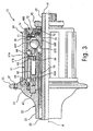
Figure 3 is an enlarged partial cross sectional view of the right-hand portion of the rear hub illustrated inFigure 2 with the right-hand bicycle hub sealing assembly in accordance with the first embodiment of the present invention; -
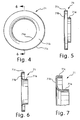
Figure 4 is a left axial end elevational view of the outer dust cap for the bicycle hub sealing assemblies illustrated inFigures 2 and3 in accordance with the first embodiment of the present invention; -
Figure 5 is a side elevational view of the outer dust cap illustrated inFigure 4 in accordance with the first embodiment of the present invention; -
Figure 6 is a cross sectional view of the outer dust cap illustrated inFigures 4 and 5 as seen along section line 6-6 ofFigure 4 ; -
Figure 7 is an enlarged partial cross sectional view of the outer dust cap illustrated inFigures 4-6 in accordance with the first embodiment of the present invention; -
Figure 8 is a left axial end elevational view of the inner dust cap for the bicycle hub sealing assemblies illustrated inFigures 2 and3 in accordance with the present invention; -
Figure 9 is a side elevational view of the inner dust cap illustrated inFigure 8 in accordance with the present invention; -
Figure 10 is a cross sectional view of the inner dust cap illustrated inFigures 8 and 9 as seen along section line 10-10 ofFigure 8 ; -
Figure 11 is an enlarged partial cross sectional view of the inner dust cap illustrated inFigures 8-10 in accordance with the present invention; -
Figure 12 is a left axial end elevational view of the inner sealing member for the bicycle hub sealing assemblies illustrated inFigures 2 and3 in accordance with the present invention; -
Figure 13 is a side elevational view of the inner sealing member illustrated inFigure 12 in accordance with the present invention; -
Figure 14 is a cross sectional view of the inner sealing member illustrated inFigures 12 and 13 as seen along section line 14-14 ofFigure 12 ; -
Figure 15 is an enlarged partial cross sectional view of the inner sealing member illustrated inFigures 12-14 in accordance with the present invention; -
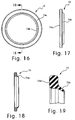
Figure 16 is a left axial end elevational view of the outer sealing member for the bicycle hub sealing assemblies illustrated inFigures 2 and3 in accordance with the present invention; -
Figure 17 is a side elevational view of the outer sealing member illustrated inFigure 16 in accordance with the present invention; -
Figure 18 is a cross sectional view of the outer sealing member illustrated inFigures 16 and 17 as seen along section line 18-18 ofFigure 16 ; -
Figure 19 is an enlarged partial cross sectional view of the outer sealing member illustrated inFigures 16-18 in accordance with the present invention; -
Figure 20 is a partial cross sectional view of the rear hub illustrating with a modified bicycle hub sealing assembly disposed on each of the ends of the rear hub in accordance with a second embodiment of the present invention; -
Figure 21 is an enlarged partial cross sectional view of the right-hand portion of the rear hub illustrated inFigure 20 with the locking nut partially unthreaded; -
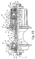
Figure 22 is a partial cross sectional view of the rear hub illustrating with a modified bicycle hub sealing assembly disposed on each of the ends of the rear hub in accordance with a third embodiment of the present invention; and -
Figure 23 is an enlarged partial cross sectional view of the right-hand portion of the rear hub illustrated inFigure 22 with the locking nut partially unthreaded. - Selected embodiments of the present invention will now be explained with reference to the drawings. It will be apparent to those skilled in the art from this disclosure that the following descriptions of the embodiments of the present invention are provided for illustration only and not for the purpose of limiting the invention as defined by the appended claims and their equivalents.
- Referring initially to
Figure 1 , abicycle 10 is illustrated that is equipped with arear hub 12 in accordance with one embodiment of the present invention. While the present invention will be illustrated in therear hub 12, it will be apparent to those skilled in art from this disclosure that the present invention can be used in other bicycle components such as a front hub, a bottom bracket, etc. Therear bicycle hub 12 is part of arear wheel 14 that is rotatably coupled to a rear fork section of a bicycle frame 16. In particular, therear wheel 14 has a plurality ofspokes 18 extending outwardly therear bicycle hub 12 to anannular rim 20 by spoke nipples (not shown). Apneumatic tire 22 is mounted on the outer surface of therim 20 in a conventional manner. Thebicycle 10 also includes adrive train 24 for propelling thebicycle 10. Thedrive train 24 includes arear derailleur 26 and a set ofrear sprockets 28 that are mounted to therear bicycle hub 12 as briefly explained below. - Since most of the parts of the
bicycle 10 are well known in the art, the parts of thebicycle 10 will not be discussed or illustrated in detail herein, except for the parts relating to therear bicycle hub 12 of the present invention. Moreover, various conventional bicycle parts such as brakes, shifters, drive train parts, derailleurs, additional sprocket, etc., which are not illustrated and/or discussed in detail herein, can also be used in conjunction with the present invention. - In the illustrated embodiment, the
rear wheel 14 has thirty-two of thespokes 18 extending between therear bicycle hub 12 and therim 20. Of course, it will be apparent to those skilled in the art from this disclosure that therear wheel 14 can have fewer or more of thespokes 18 than illustrated, if needed and/or desired. Each of thespokes 18 has an outer threaded end or spoke head coupled to therim 20 by a spoke nipple and an inner bent end coupled to therear bicycle hub 12 in a conventional manner. More specifically, the outer ends of thespokes 18 are threadedly coupled to therim 20 by the spoke nipples to adjust the tension in thespokes 18. - The
rim 20 is constructed of a substantially rigid material, such as those materials, which are well known in the art. For example, therim 20 can be constructed of any suitable metallic material, such as plated steel, stainless steel, aluminum, magnesium or titanium, as well as other non-metallic materials, such as a carbon fiber composite, which can be utilized for a bicycle wheel. Therim 20 is relatively conventional. Therefore, therim 20 will not be discussed or illustrated in detail herein. - As seen in
Figure 2 , thebicycle hub assembly 12 basically includes ahub axle 30 and ahub shell 32 with afreewheel 34 for receiving therear sprockets 28. Thehub axle 30 and the various parts that are fixedly coupled to rotate with thehub axle 30 are collectively referred to herein as a fixed part of the bicycle component. Thehub shell 32 and thefreewheel 34 form a rotatable hub member (rotatable part) that is mounted on thehub axle 30 for rotation. In particular, the rotatable hub member (thehub shell 32 and the freewheel 34) is rotatably mounted on thehub axle 30 by a pair of bearingassemblies freewheel 34 includes a one-way clutch that limits rotation of thehub shell 32 to one rotational direction relative to thehub axle 30. - The ends of the
bicycle hub assembly 12 are sealed by a pair ofbicycle sealing assemblies hub axle 30 and the rotatable hub member (thehub shell 32 and the freewheel 34). Thebicycle sealing assembly 40R is disposed between thehub axle 30 and thefreewheel 34 that forms a first rotatable end of the rotatable hub member (thehub shell 32 and the freewheel 34). Thebicycle sealing assembly 40L is disposed between thehub axle 30 and thehub shell 32 that forms a second rotatable end of the rotatable hub member (thehub shell 32 and the freewheel 34). - The
hub axle 30 is a hard, rigid tubular member that has a first orright axle end 41 and a second or leftaxle end 42 with a center axis A extending between the first and second axle ends 41 and 42. Thefirst axle end 41 is provided withexternal threads 43, while thesecond axle end 42 is provided withexternal threads 44. Afirst locking nut 45 is threaded on to theexternal threads 43 of thefirst axle end 41, while asecond locking nut 46 is threaded on to theexternal threads 44 of thesecond axle end 42. - Preferably, the
hub shell 32 is preferably formed as a one-piece, unitary member. It will be apparent to those skilled in the art that thehub shell 32 can be constructed of any substantially rigid material, such as those materials, which are known in the art. For example, thehub shell 32 can be constructed of any suitable metallic material, such as plated steel, stainless steel, aluminum, magnesium or titanium, as well as other non-metallic materials, such as carbon fiber composite, ceramic or plastic. Of course, thehub shell 32 could be constructed of several pieces of various different materials as need and/or desired. - Still referring to
Figure 2 , thehub shell 32 has a first orright shell end 51 and a second or leftshell end 52 with acenter tubular portion 53 located therebetween. The first and second hub shell ends 51 and 52 are integral formed with thecenter tubular portion 53 as a one-piece, unitary member. Thehub shell 32 is a tubular member having an inner tubular surface forming a central interior passage extending between the first and second shell ends 51 and 52. Thehub axle 30 is coaxially disposed within the central passage of thehub shell 32. The first andsecond bearing hub shell 32 on thehub axle 30 for rotating thehub shell 32 relative to thehub axle 30. - The
first shell end 51 has a first spoke attachment portion orflange 55 with thefreewheel 34 operatively coupled thereto. Thesecond shell end 52 has a second spoke attachment portion orflange 56. Thus, therim 20 is coupled to the first and second spokeflanges spokes 18. The first spokeflange 55 is preferably an annular member with a plurality of first spoke holes 57 (e.g., sixteen in the illustrated embodiment but only one shown inFigure 2 ). In this embodiment, the first spoke holes are equally spaced apart about the imaginary circle that is centered on the axis A. The first spoke holes 57 are arranged to receiving the bent ends of thespokes 18. Similarly, thesecond spoke flange 56 is preferably an annular member with a plurality of second spoke holes 58 for receiving the bent ends of thespokes 18. In the illustrated embodiment, the second spoke holes 58 are equally spaced apart about the imaginary circle that is centered on the center axis A of thehub axle 30. - Referring again to
Figure 3 , thefreewheel 34 is operatively coupled between thefirst axle end 41 of thehub axle 30 and thefirst shell end 51 of thehub shell 32. Thefreewheel 34 basically includes of a driving (outer)cylinder 61, a driven (inner)cylinder 62, a plurality of springbiased pawls 63, two sets ofball bearings 64 that are axially spaced apart, and a serrationmain body 65. Thefreewheel 34 is relatively conventional, and thus, will not be discussed or illustrated in detail herein. For example, thefreewheel 34 of the illustrated embodiment is constructed in accordance withU.S. Patent No. 6,202,813 that is assigned to Shimano, Inc. Thefreewheel 34 is coupled to thehub shell 32 in a relatively conventional manner as will be briefly explained below. Thesprockets 28 are mounted on thefreewheel 34 in a relatively conventional manner such that rotation of thesprockets 28 results in rotation of thefreewheel 34. Rotation of thefreewheel 34 relative to thehub axle 30 in turn rotates thehub shell 32. - The driving (outer)
cylinder 61 is a tubular member having a roughly cylindrical shape. The free end portion of the driving (outer)cylinder 61 forms the first rotatable end of the rotatable hub member (thehub shell 32 and the freewheel 34). The outer peripheral surface of the driving (outer)cylinder 61 is provided with a plurality of axially extendingsplines 61a for fixedly attaching thesprockets 28. In other words, thesplines 61 a non-rotatably couple thesprockets 28 to the outer peripheral surface of the drivingcylinder 61. Thus, thesprockets 28 are mounted to the drivingcylinder 61 for transmitting torque to thehub shell 32 via the unidirectional rotation transmission mechanism of thefree wheel 34. The inner peripheral surface of the interior opening of the drivingcylinder 61 has a plurality ofratchet teeth 61b that forms a first part of the unidirectional rotation transmission mechanism of thefreewheel 34. The inner peripheral surface of the drivingcylinder 61 is also rotatably supported on the driven (inner)cylinder 62 by theball bearings 64. - The driven (inner)
cylinder 62 is inserted and disposed coaxially about thehub axle 30 and coaxially within the driving (outer)cylinder 61. The driven (inner)cylinder 62 is fixed to thehub shell 32 by the serrationmain body 65, which is fixed to the hub sell 32 by interlocking serrations. In particular, the driven (inner)cylinder 62 has an inner peripheral surface withserrated teeth 62a that are interlocked with external serrations of the serrationmain body 65. Thus, the driven (inner)cylinder 62 rotates with thehub shell 32. - The driven (inner)
cylinder 62 is designed to hold thepawls 63 in such a manner as explained, for example, inU.S. Patent No. 6,202,813 . Each of thepawls 63 is pivotally mounted on the driven (inner)cylinder 62 and biased to an extended position by a coil torsion-spring 66 such that thepawls 63 normally engage theratchet teeth 61b of the driving (outer)cylinder 61. Thepawls 63 and thesprings 66 are configured and arranged to operatively couple the driving (outer)cylinder 61 to the driven (inner)cylinder 62 when rotated in a first rotational direction and disconnect the driving (outer)cylinder 61 from the driven (inner)cylinder 62 when rotated in a second rotational direction that is opposite the first rotational direction. In other words, ratchetteeth 61b together with thepawls 63 and thesprings 66 form a unidirectional rotation transmission or one-way clutch that is operatively coupled between the drivingcylinder 61 and the drivencylinder 62. Accordingly, the driven (inner)cylinder 62 is adapted, by means of the unidirectional rotation transmission mechanism and theball bearings 64, to freely rotate in one direction relative to the drivingcylinder 61. - Since bearing assemblies, similar to the
bearing assemblies assemblies hand bearing assembly 36 is disposed between thefirst axle end 41 of thehub axle 30 and the freewheel 34 (part of the rotatable hub member) to rotatably support thefirst shell end 51 of thehub shell 32 and thefreewheel 34 on thefirst axle end 41 of thehub axle 30. - As seen in
Figures 2 and3 , the first or righthand bearing assembly 36 preferably includes a plurality of first rolling members orballs 67R disposed between a first inner race orcone 68R threadedly coupled to thefirst axle end 41 of thehub axle 30 and a first outer race orcone 69R threadedly coupled to the driven (inner)cylinder 62 that is fixed to thehub shell 32. The firstinner cone 68R includes a first inner angular bearing surface contacting one axial side of thefirst rolling members 67R such that firstinner cone 68R contacts and supports each of thefirst rolling members 67R at an inner peripheral area. The firstouter race 69R includes a first outer angular bearing surface contacting thefirst rolling members 67R on an axial side that is opposite from the first inner angular bearing surface such that the firstouter race 69R contacts and supports each of thefirst rolling members 67R at an outer peripheral area. - As seen in
Figure 2 , the second or lefthand bearing assembly 38 is disposed between thesecond axle end 42 of thehub axle 30 and thesecond shell end 52 of thehub shell 32 to rotatably support thehub shell 32 on thesecond axle end 42 of thehub axle 30. The second or lefthand bearing assembly 38 preferably includes a plurality of second rolling members orballs 67L disposed between a second inner race orcone 68L threadedly coupled to thesecond axle end 42 of thehub axle 30 and a second outer race orcone 69L threadedly coupled to the interior of thesecond shell end 52 of thehub shell 32. - As seen in
Figure 2 , the secondinner cone 68L includes a second inner angular bearing surface contacting one axial side of thefirst rolling members 67L such that the secondinner cone 68L contacts and supports each of thefirst rolling members 67L at an inner peripheral area. The secondouter race 69L includes a second outer angular bearing surface contacting thefirst rolling members 67L on an axial side that is opposite from the second inner angular bearing surface such that the secondouter race 69L contacts and supports each of thesecond rolling members 67L at an outer peripheral area. - The bicycle
hub sealing assemblies hub sealing assemblies hub sealing assemblies hub sealing assembly 40R is disposed between thefirst axle end 41 of thehub axle 30 and the first rotatable end of the driving (outer)cylinder 61, which constitutes part of the rotatable hub member. The bicyclehub sealing assembly 40L is disposed between thesecond axle end 42 of thehub axle 30 and the secondhub shell end 52 of thehub shell 32, which constitutes part of the rotatable hub member. Each of the bicyclehub sealing assemblies dust cap 71, a second (inner)dust cap 72, a first (inner) sealingmember 73, a second (outer) sealingmember 74, and aseal base nut 75. - Referring now to
Figures 2 and4-7 , the first (outer)dust cap 71 that is located on the right hand side of thehub 12 is fixedly coupled to the first rotatable end of the driving (outer) cylinder 61 (part of the rotatable hub member), while the first (outer)dust cap 71 that is located on the left hand side of thehub 12 is fixedly coupled to thehub shell end 52 of thehub shell 32. The first (outer) dust caps 71 are press fitted to the driving (outer)cylinder 61 and thehub shell 32 so that that rotate therewith. Eachfirst dust cap 71 is a one-piece, unitary member made of a rigid sheet metal material having a small degree of flexibility. Preferably, the first dust caps 71 are an annular ring shaped members with a uniform cross-sectional profile. In other words, the cross section of thefirst dust cap 71 at any point preferably has the same cross section as seen inFigure 7 . - As seen in
Figure 7 , each of the first dust caps 71 basically has a C-shaped cross section that includes an inneraxial portion 71a, a middleradial portion 71b and an outeraxial portion 71c. The inneraxial portion 71a is a tubular portion that extends in a generally axial direction. The middleradial portion 71b is an annular ring shaped portion that extends in a generally radial direction between the inneraxial portion 71 a and the outeraxial portion 71 c. The outeraxial portion 71 c is a tubular portion that extends in a generally axial direction and directly contacts the inner peripheral surface of the drivingcylinder 61. Thus, thefirst dust cap 71 rotates with thefreewheel 34. - As seen in
Figure 2 , the inneraxial portion 71a of thefirst dust cap 71 is configured and arranged to overlap with thesecond dust cap 73 as explained below. The inneraxial portion 71a of thefirst dust cap 71 has a radially inwardly facing that contacts the first (inner) sealingmember 73 to create a seal therebetween. The outeraxial portion 71c of thefirst dust cap 71 has a radially inwardly facing that contacts the second (outer) sealingmember 73 to create a seal therebetween. - Referring now to
Figures 2 and8-11 , the second (inner) dust caps 72 are fixedly coupled to the first and second axle ends 41 and 42 of thehub axle 30 by the first andsecond locking nuts external threads hub axle 30. The second dust caps 72 are a one-piece, unitary members made of a rigid sheet metal material having a small degree of flexibility. Preferably, eachsecond dust cap 72 is an annular ring shaped member with a uniform cross-sectional profile. In other words, the cross section of thesecond dust cap 72 at any point preferably has the same cross section as seen inFigure 11 . - As seen in
Figure 11 , each of the second dust caps 72 basically has an L-shaped cross section that includes an outeraxial portion 72a and aradial portion 72b. The outeraxial portion 72a is a tubular portion that extends in a generally axial direction. Theradial portion 72b is an annular ring shaped portion that extends in a generally radial direction from one end of the outeraxial portion 72a. At each end of thehub 12, the inneraxial portion 71a of thefirst dust cap 71 is arranged to overlap with the outeraxial portion 72a of thesecond dust cap 72. In particular, the inneraxial portion 71 a of thefirst dust cap 71 is arranged below the outeraxial portion 72a of thesecond dust cap 72 as seen inFigure 11 . - The outer
axial portion 72a of thesecond dust cap 72 has a radially outwardly facing surface that is stepped to form an annular abutment portion orsurface 72c and a contact portion orsurface 72d that contacts the second sealingmember 74 to create a seal therebetween. Theannular abutment portion 72c is configured and arranged to prevent axial movement of the second sealingmember 74 along thecontact surface 72d of thesecond dust cap 72. Theabutment portion 72c is preferably an angled abutment surface that is angled approximately thirty degrees relative to a line parallel to the center axis A of thebicycle sealing assembly 40R. - Referring now to
Figures 2 and12-15 , each of the first (inner) sealingmembers 73 is slideably disposed between a corresponding one of the first dust caps 71 (rotational part) and a corresponding one of the seal base nuts 75 (fixed part). Of course, thefirst sealing members 73 can be configured and arranged to contact either theseal base nut 75 or thesecond dust cap 72 to form a seal therebetween. Each first sealingmember 73 is a one-piece, unitary member made of a resilient flexible sealing material such as an elastomeric material having good sealing qualities. Preferably, thefirst sealing members 73 are an annular ring shaped member with a uniform cross-sectional profile. In other words, the cross section of each first sealingmember 73 at any point preferably has the same cross section as seen inFigure 15 . - As seen in
Figure 15 , each of thefirst sealing members 73 has a cross sectional shape that includes amain body portion 73a, an outersealing flange portion 73b and an innersealing flange portion 73c. The outersealing flange portion 73b has an outer seal surface that directly contacts the radially inwardly facing surface of the inneraxial portion 71a of thefirst dust cap 71 to form a seal therebetween. The innersealing flange portion 73c has an inner seal surface that directly contacts the radially outwardly facing surface of the seal base nut 75 (fixed part) to form a seal therebetween. Thefirst sealing member 73 is configured and arranged relative to thefirst dust cap 71, the seal base nut 75 (fixed part) and thesecond dust cap 72 to float in an axial direction. - Referring now to
Figures 2 and16-19 , the second (outer) sealingmembers 74 are disposed between a corresponding one of the second dust caps 72 (fixed part) and a corresponding one of the first dust caps 71 (rotational part) to form a second seal therebetween. Of course, the second sealingmember 74 can be configured and arranged to contact either thefirst dust cap 71 or the drivingcylinder 61 to form a seal therebetween. Thesecond sealing member 74 is a one-piece, unitary member made of a resilient flexible sealing material such as an elastomeric material having good sealing qualities. Preferably, the second sealingmember 74 is an annular ring shaped member with a uniform cross-sectional profile. In other words, the cross section of the second sealingmember 74 at any point preferably has the same cross section as seen inFigure 19 . - As seen in
Figure 19 , each of thesecond sealing members 74 has a cross sectional shape that includes amain body portion 74a with an innersealing flange portion 74b. As seen inFigure 2 , themain body portion 74a of the second sealingmember 74 is press fitted into thefirst dust cap 71 such that an outer seal surface of themain body portion 74a of the second sealingmember 74 contacts the radially inwardly facing surface of the outeraxial portion 71c of thefirst dust cap 71 to create a seal therebetween. The innersealing flange portion 74b contacts a radially outwardly facing portion of thecontact surface 72d of thesecond dust cap 72 such that an inner seal surface of the innersealing flange portion 74b of the second sealingmember 74 contacts the radially outwardly facing surface of the outeraxial portion 72a of thesecond dust cap 72 to create a seal therebetween. The free end or tip of the innersealing flange portion 74b contacts theannular abutment portion 72c to prevent axial movement of the second sealingmember 74 along thecontact surface 72d of thesecond dust cap 72. - As seen in
Figures 2 and3 , theseal base nuts 75 are threaded on to theexternal threads seal base nuts 75 has a step shaped outer peripheral surface for receiving the first sealingmember 73 thereon. The step shaped outer peripheral surface of theseal base nut 75 is configured and arrange such that the first sealingmember 73 can float relative in an axial direction relative to thefirst dust cap 71, the seal base nut 75 (fixed part) and thesecond dust cap 72. - Referring now to
Figures 20 and21 , arear hub 212 is illustrated in accordance with a second embodiment. In view of the similarity between the first and second embodiments, the parts of the second embodiment that are identical to the parts of the first embodiment will be given the same reference numerals as the parts of the first embodiment. Moreover, the descriptions of the parts of the second embodiment that are identical to the parts of the first embodiment may be omitted for the sake of brevity. - Basically, the
rear hub 212 is identical to therear hub 12, except that thesealing assemblies sealing assemblies seal base nuts 75 have been eliminated in thesealing assemblies rear hub 212, and the dust caps 72 and theseals 73 have been each replaced with aninner dust cap 272 and aninner seal 273 in therear hub 212. In other words, each of the sealingassemblies rear hub 212 includes the first (outer)dust cap 71, the second (inner)dust cap 272, the first (inner) sealingmember 273, and the second (outer) sealingmember 74. Thus, in this embodiment, theinner seal 273 directly contacts theinner dust cap 272 and theouter dust cap 71 to create a seal therebetween. - As seen in
Figure 20 , the inner dust caps 272 are fixedly coupled to the first and second axle ends 41 and 42 of thehub axle 30 by the first andsecond locking nuts external threads hub axle 30. Eachinner dust cap 272 is a one-piece, unitary member made of a rigid sheet metal material having a small degree of flexibility. Preferably, the inner dust caps 272 are an annular ring shaped member with a uniform cross-sectional profile. In other words, the cross section of theinner dust cap 272 at any point preferably has the same cross section. As seen inFigure 21 , theinner dust cap 272 basically has a C-shaped cross section that includes an outeraxial portion 272a, aradial portion 272b and an inneraxial portion 272c. The outeraxial portion 272a is a tubular portion that extends in a generally axial direction. Theradial portion 272b is an annular ring shaped portion that extends in a generally radial direction from between the outeraxial portion 272a and the inneraxial portion 272c. The inneraxial portion 71a of theouter dust cap 71 is arranged to overlap with the outeraxial portion 272a of thesecond dust cap 272. In particular, the inneraxial portion 71a of theouter dust cap 71 is arranged below the outeraxial portion 272a of theinner dust cap 272. The inneraxial portion 272c is a tubular portion that extends in a generally axial direction from the inner end of theradial portion 272b with its inner surface contacting thehub axle 30. If desired, theaxial portion 272c can be threaded to engage the threads of thehub axle 30. - The outer
axial portion 272a of theinner dust cap 272 has a radially outwardly facing surface that is stepped to form an annular abutment portion orsurface 272d and a contact portion orsurface 272e that contacts the outer sealingmember 74 to create a seal therebetween. Theannular abutment portion 272d is configured and arranged to prevent axial movement of the outer sealingmember 74 along thecontact surface 272e of theinner dust cap 272. Theabutment portion 272d is preferably an angled abutment surface that is angled approximately thirty degrees relative to a line parallel to the center axis A of thebicycle sealing assembly - Still referring to
Figure 21 , theinner sealing member 273 is slideably disposed between the outer dust cap 71 (rotational part) and the inner dust cap 272 (fixed part). Theinner sealing member 273 is a one-piece, unitary member made of a resilient flexible sealing material such as an elastomeric material having good sealing qualities. Preferably, theinner sealing member 273 is an annular ring shaped member with a uniform cross-sectional profile. In other words, the cross section of theinner sealing member 273 at any point preferably has the same cross section. Theinner sealing member 273 has a cross sectional shape that includes amain body portion 273a, an outersealing flange portion 273b and an innersealing flange portion 273c. The outersealing flange portion 273b has an outer seal surface that directly contacts the radially inwardly facing surface of the inneraxial portion 71a of theouter dust cap 71 to form a seal therebetween. The innersealing flange portion 273c has an inner seal surface that directly contacts the radially outwardly facing surface of the inner dust cap 272 (fixed part) to form a seal therebetween. Theinner sealing member 273 is configured and arranged relative to theouter dust cap 71 and the inner dust cap 272 (fixed part) to float in an axial direction. - Referring now to
Figures 22 and23 , arear hub 312 is illustrated in accordance with a third embodiment. In view of the similarity between the first and third embodiments, the parts of the third embodiment that are identical to the parts of the first embodiment will be given the same reference numerals as the parts of the first embodiment. Moreover, the descriptions of the parts of the third embodiment that are identical to the parts of the first embodiment may be omitted for the sake of brevity. - Basically, the
rear hub 312 is identical to therear hub 12, except that thesealing assemblies sealing assemblies outer seals 74 have been each replaced with anouter seal 374 in therear hub 312. In other words, each of the sealingassemblies rear hub 312 includes the first (outer)dust cap 71, the second (inner)dust cap 72, the first (inner) sealingmember 73, and the second (outer) sealingmember 374. Thus, in this embodiment, theouter seal 374 directly contacts the drivingcylinder 61 and theinner dust cap 72 to create a seal therebetween. - Referring to
Figure 22 , theouter sealing members 374 are one-piece, unitary members made of a resilient flexible sealing material such as an elastomeric material having good sealing qualities. Preferably, theouter sealing members 374 are annular ring shaped members with a uniform cross-sectional profile. In other words, the cross section of the outer sealingmember 374 at any point preferably has the same cross section. Each outer sealingmember 374 has a cross sectional shape that includes amain body portion 374a with an innersealing flange portion 374b as seen inFigure 23 . Themain body portion 374a of thesecond sealing member 374 is press fitted into the drivingcylinder 61 on the right hand side of thehub 312 such that an outer seal surface of themain body portion 374a of the outer sealingmember 374 contacts the radially inwardly facing surface of the drivingcylinder 61 to create a seal therebetween. Themain body portion 374a of thesecond sealing member 374 is press fitted into thesecond end 52 of thehub shell 32 on the left hand side of thehub 312 such that an outer seal surface of themain body portion 374a of the outer sealingmember 374 contacts the radially inwardly facing surface of thesecond end 52 of thehub shell 32 to create a seal therebetween. The innersealing flange portions 374b contact a radially outwardly facing portion of a corresponding one of thecontact surface 72d of the correspondinginner dust cap 72 such that an inner seal surface of the innersealing flange portion 374b of theinner sealing member 374 contacts the radially outwardly facing surface of the corresponding outeraxial portion 72a of the correspondinginner dust cap 72 to create a seal therebetween. The free end or tip of the innersealing flange portion 374b contacts theannular abutment portion 72c to prevent axial movement of thesecond sealing member 374 along thecontact surface 72d of the correspondinginner dust cap 72. - As used herein to describe and claim the above embodiments, the following directional terms "inner, outer, forward, rearward, above, downward, vertical, horizontal, below and transverse" as well as any other similar directional terms refer to those directions of a bicycle equipped with the present invention. Accordingly, these terms, as utilized to describe the present invention should be interpreted relative to a bicycle equipped with the present invention. Also the terms of degree such as "substantially", "about" and "approximately" as used herein mean a reasonable amount of deviation of the modified term such that the end result is not significantly changed. These terms should be construed as including a deviation of at least ± 5% of the modified term if this deviation would not negate the meaning of the word it modifies.
- While only selected embodiments have been chosen to illustrate the present invention, it will be apparent to those skilled in the art from this disclosure that various changes and modifications can be made herein without departing from the scope of the invention as defined in the appended claims. Furthermore, the foregoing descriptions of the embodiments according to the present invention are provided for illustration only, and not for the purpose of limiting the invention as defined by the appended claims and their equivalents.
Claims (20)
- A bicycle sealing assembly (40R, 40L) comprising:a first dust cap (71) configured and arranged to be attached to a rotational part of a bicycle;a second dust cap (72, 272) configured and arranged to be attached to a fixed part of a bicycle;a first sealing member (73, 273) disposed between the first dust cap (71) and either the fixed part or the second dust cap (72, 272) to form a first seal therebetween; anda second sealing member (74, 374) disposed between the second dust cap (72, 272) and either the first dust cap (71) or the rotational part to form a second seal therebetween;characterized in that the first sealing member (73, 273) is slideably disposed between the first dust cap (71) and one of the second dust cap (72, 272) and the fixed part of the bicycle, and is configured and arranged floatably in an axial direction relative to the first dust cap (71), the fixed part of the bicycle and the second dust cap (72, 272).
- The bicycle sealing assembly (40R, 40L) as recited in claim 1, wherein
the first sealing member (73, 273) contacts a radially inwardly facing surface of the first dust cap (71); and
the second sealing member (74, 374) contacts a radially outwardly facing surface of the second dust cap (72, 272). - The bicycle sealing assembly (40R, 40L) as recited in claim 1 or 2, wherein
the second dust cap (72, 272) includes an abutment portion (72c, 272d) contacting the second sealing member (74, 374) and arranged to prevent axial movement of the second sealing member (74, 374) along a contact surface of the second dust cap (72, 272). - The bicycle sealing assembly (40R, 40L) as recited in any of the preceding claims, wherein
the first sealing member (73, 273) is configured and arranged to contact a seal base nut (75) that forms a portion of the fixed part of the bicycle. - The bicycle sealing assembly (40R, 40L) as recited in any of the preceding claims, wherein
the first dust cap (71) includes an inner portion extending in an axial direction; and
the second dust cap (72, 272) includes an outer portion extending in an axial direction and arranged to overlap with the inner portion of the first dust cap (71). - The bicycle sealing assembly (40R, 40L) as recited in any of the preceding claims, wherein
the second sealing member (74, 374) is press fitted on the first dust cap (71) or the rotational part. - The bicycle sealing assembly (40R, 40L) as recited in any of the preceding claims, wherein
the second sealing member (74, 374) includes an outer seal surface contacting the radially inwardly facing surface of the first dust cap (71) and an inner seal surface contacting the radially outwardly facing surface of the second dust cap (72, 272). - The bicycle sealing assembly (40R, 40L) as recited in claim 3, wherein
the first sealing member (73, 273) includes an outer seal surface contacting the radially inwardly facing surface of the first dust cap (71). - The bicycle sealing assembly (40R, 40L) as recited in claim 8, wherein
the first dust cap (71) includes an inner portion extending in an axial direction with the radially inwardly facing surface formed thereon,
the second dust cap (72, 272) includes an outer portion extending in an axial direction with the radially outwardly facing surface formed thereon, and
the inner portion of the first dust cap (71) being arranged to overlap with the outer portion of the second dust cap (72, 272). - The bicycle sealing assembly (40R, 40L) as recited in claim 8 or 9, wherein
the inner portion of the first dust cap (71) is arranged below the outer portion of the second dust cap (72, 272). - The bicycle sealing assembly (40R, 40L) as recited in any of the preceding claims, wherein
the first and second dust caps (71; 72, 272) are made of a sheet metal material. - The bicycle sealing assembly (40R, 40L) as recited in claim 3, wherein
the abutment portion (72c, 272d) has an angled abutment surface that is angled approximately thirty degrees relative to a line parallel to a center axis (A) of the bicycle sealing assembly (40R, 40L; 240R, 240L; 340R, 340L). - The bicycle sealing assembly (40R, 40L) as recited in any of the preceding claims, wherein
the first sealing member (73, 273) contacts the first dust cap (71) and the fixed part to form the first seal therebetween. - The bicycle sealing assembly (40R, 40L) as recited in claim 13, wherein
the second sealing member (74, 374) contacts the second dust cap (72, 272) and
the first dust cap (71) to form the second seal therebetween. - The bicycle sealing assembly (40R, 40L) as recited in any of claims 1 to 12, wherein the second sealing member (74, 374) contacts the second dust cap (72, 272) and the first dust cap (71) to form the second seal therebetween.
- The bicycle sealing assembly (40R, 40L) as recited in any of claims 1 to 12, wherein the first sealing member (73, 273) contacts the first dust cap (71) and second dust cap (72, 272) to form the first seal therebetween.
- The bicycle sealing assembly (40R, 40L) as recited in claim 16, wherein
the second sealing member (74, 374) contacts the second dust cap (72, 272) and the rotational part to form the second seal therebetween. - A bicycle component comprising:a fixed part with a center axis (A);a rotatable part having an inner tubular surface forming a central passage, the fixed part being rotatably disposed within the central passage of the rotatable part; anda bicycle sealing assembly (40R, 40L) according to any of the claims 1 to 17.
- The bicycle component as recited in claim 18 wherein
the fixed part is a hub axle (30), and the rotatable part is a freewheel (34). - The bicycle component as recited in claim 18 wherein
the fixed part is a hub axle (30), and the rotatable part is a hub shell (32).
Applications Claiming Priority (2)
| Application Number | Priority Date | Filing Date | Title |
|---|---|---|---|
| US781934 | 1985-09-30 | ||
| US10/781,934 US7029075B2 (en) | 2004-02-20 | 2004-02-20 | Bicycle hub sealing assembly |
Publications (3)
| Publication Number | Publication Date |
|---|---|
| EP1566287A2 EP1566287A2 (en) | 2005-08-24 |
| EP1566287A3 EP1566287A3 (en) | 2006-12-27 |
| EP1566287B1 true EP1566287B1 (en) | 2008-11-19 |
Family
ID=34711856
Family Applications (1)
| Application Number | Title | Priority Date | Filing Date |
|---|---|---|---|
| EP04021002A Expired - Lifetime EP1566287B1 (en) | 2004-02-20 | 2004-09-03 | Bicycle hub sealing assembly |
Country Status (6)
| Country | Link |
|---|---|
| US (1) | US7029075B2 (en) |
| EP (1) | EP1566287B1 (en) |
| JP (1) | JP2005231617A (en) |
| CN (1) | CN1657808A (en) |
| DE (1) | DE602004017833D1 (en) |
| TW (1) | TW200530055A (en) |
Cited By (1)
| Publication number | Priority date | Publication date | Assignee | Title |
|---|---|---|---|---|
| EP2452865B1 (en) | 2010-11-12 | 2016-08-10 | Shimano Inc. | Sprocket support structure |
Families Citing this family (51)
| Publication number | Priority date | Publication date | Assignee | Title |
|---|---|---|---|---|
| US7011600B2 (en) | 2003-02-28 | 2006-03-14 | Fallbrook Technologies Inc. | Continuously variable transmission |
| KR101276082B1 (en) | 2004-10-05 | 2013-06-18 | 폴브룩 테크놀로지즈 인크 | Continuously variable transmission |
| DE602005003547T2 (en) * | 2005-01-27 | 2008-10-23 | Shimano Inc., Sakai | Fahrradantriebsnabe |
| DE602005004505T2 (en) * | 2005-02-28 | 2009-02-05 | Shimano Inc., Sakai | Cover for a bicycle hub shifter |
| US7191884B2 (en) * | 2005-02-28 | 2007-03-20 | Shimano Inc. | Bicycle hub |
| US7461904B2 (en) * | 2005-06-17 | 2008-12-09 | Shimano Inc. | Bicycle hub sealing structure |
| JP4157883B2 (en) * | 2005-07-29 | 2008-10-01 | 株式会社シマノ | Cap member for bicycle internal gear shifting hub |
| KR101831828B1 (en) | 2005-10-28 | 2018-02-23 | 폴브룩 인텔렉츄얼 프로퍼티 컴퍼니 엘엘씨 | Electromotive drives |
| EP1954959B1 (en) | 2005-11-22 | 2013-05-15 | Fallbrook Intellectual Property Company LLC | Continuously variable transmission |
| CA2976893C (en) | 2005-12-09 | 2019-03-12 | Fallbrook Intellectual Property Company Llc | Continuously variable transmission |
| EP1811202A1 (en) | 2005-12-30 | 2007-07-25 | Fallbrook Technologies, Inc. | A continuously variable gear transmission |
| JP2007290606A (en) * | 2006-04-26 | 2007-11-08 | Shimano Inc | Hub for bicycle |
| CN102278200B (en) | 2006-06-26 | 2014-05-14 | 福博科知识产权有限责任公司 | Continuously variable transmission |
| EP2125469A2 (en) | 2007-02-01 | 2009-12-02 | Fallbrook Technologies Inc. | System and methods for control of transmission and/or prime mover |
| CN104121345B (en) | 2007-02-12 | 2017-01-11 | 福博科知识产权有限责任公司 | Continuously variable transmission and method therefor |
| EP2700843A3 (en) | 2007-02-16 | 2017-11-08 | Fallbrook Intellectual Property Company LLC | Infinitely variable transmissions, continuously variable transmissions, methods, assemblies, subassemblies, and components therefor |
| CN102943855B (en) | 2007-04-24 | 2016-01-27 | 福博科技术公司 | Electric traction drives |
| WO2008154437A1 (en) | 2007-06-11 | 2008-12-18 | Fallbrook Technologies Inc. | Continuously variable transmission |
| CN103697120B (en) | 2007-07-05 | 2017-04-12 | 福博科技术公司 | Continuously variable transmission |
| TW200916339A (en) * | 2007-09-06 | 2009-04-16 | Aleksandr Sherman | Bicycle wheel |
| US8996263B2 (en) | 2007-11-16 | 2015-03-31 | Fallbrook Intellectual Property Company Llc | Controller for variable transmission |
| JP5783723B2 (en) | 2007-12-21 | 2015-09-24 | フォールブルック インテレクチュアル プロパティー カンパニー エルエルシー | Automatic transmission and method thereof |
| CA2716908C (en) | 2008-02-29 | 2017-06-27 | Fallbrook Technologies Inc. | Continuously and/or infinitely variable transmissions and methods therefor |
| US8317651B2 (en) | 2008-05-07 | 2012-11-27 | Fallbrook Intellectual Property Company Llc | Assemblies and methods for clamping force generation |
| US8535199B2 (en) | 2008-06-06 | 2013-09-17 | Fallbrook Intellectual Property Company Llc | Infinitely variable transmissions, continuously variable transmissions, methods, assemblies, subassemblies, and components therefor |
| WO2009157920A1 (en) | 2008-06-23 | 2009-12-30 | Fallbrook Technologies Inc. | Continuously variable transmission |
| WO2010017242A1 (en) | 2008-08-05 | 2010-02-11 | Fallbrook Technologies Inc. | Methods for control of transmission and prime mover |
| US8469856B2 (en) | 2008-08-26 | 2013-06-25 | Fallbrook Intellectual Property Company Llc | Continuously variable transmission |
| US8167759B2 (en) | 2008-10-14 | 2012-05-01 | Fallbrook Technologies Inc. | Continuously variable transmission |
| KR101005259B1 (en) | 2008-12-09 | 2011-01-04 | 안왕기 | Bicycle Hub |
| WO2010120933A1 (en) | 2009-04-16 | 2010-10-21 | Fallbrook Technologies Inc. | Stator assembly and shifting mechanism for a continuously variable transmission |
| JP5116779B2 (en) * | 2010-01-08 | 2013-01-09 | 書偉 林 | Bicycle hub manufacturing method and product |
| US8512195B2 (en) | 2010-03-03 | 2013-08-20 | Fallbrook Intellectual Property Company Llc | Infinitely variable transmissions, continuously variable transmissions, methods, assemblies, subassemblies, and components therefor |
| US8888643B2 (en) | 2010-11-10 | 2014-11-18 | Fallbrook Intellectual Property Company Llc | Continuously variable transmission |
| US8393794B1 (en) * | 2011-09-12 | 2013-03-12 | Shimano Inc. | Bicycle bottom bracket assembly |
| CN107061653B (en) | 2012-01-23 | 2020-05-26 | 福博科知识产权有限责任公司 | Infinitely variable transmissions, continuously variable transmissions, methods, assemblies, subassemblies, and components thereof |
| US8979387B2 (en) * | 2012-09-11 | 2015-03-17 | Shimano Inc. | Bicycle hub assembly |
| US9085197B2 (en) * | 2012-09-28 | 2015-07-21 | Shimano Inc. | Bicycle hub kit |
| KR102433297B1 (en) | 2013-04-19 | 2022-08-16 | 폴브룩 인텔렉츄얼 프로퍼티 컴퍼니 엘엘씨 | Continuously variable transmission |
| CN103738114B (en) * | 2013-12-31 | 2016-08-17 | 久裕交通器材(深圳)有限公司 | A kind of bicycle drive shaft seals structure |
| US20160136996A1 (en) * | 2014-11-16 | 2016-05-19 | Robert Sweeting | Single Shell Bicycle Hub with Enlarged Drive-Side Flange |
| US10047861B2 (en) | 2016-01-15 | 2018-08-14 | Fallbrook Intellectual Property Company Llc | Systems and methods for controlling rollback in continuously variable transmissions |
| US10458526B2 (en) | 2016-03-18 | 2019-10-29 | Fallbrook Intellectual Property Company Llc | Continuously variable transmissions, systems and methods |
| US10023266B2 (en) | 2016-05-11 | 2018-07-17 | Fallbrook Intellectual Property Company Llc | Systems and methods for automatic configuration and automatic calibration of continuously variable transmissions and bicycles having continuously variable transmissions |
| US10995806B2 (en) | 2017-07-26 | 2021-05-04 | Dt Swiss Inc. | Hub, in particular for bicycles |
| US10549578B2 (en) | 2016-07-26 | 2020-02-04 | Dt Swiss Inc. | Hub, in particular for bicycles |
| US10625540B2 (en) | 2017-07-26 | 2020-04-21 | Dt Swiss Inc. | Hub, in particular for bicycles |
| US11208171B2 (en) * | 2017-09-21 | 2021-12-28 | Veselin Mandaric | Drive assembly for a bicycle |
| US11215268B2 (en) | 2018-11-06 | 2022-01-04 | Fallbrook Intellectual Property Company Llc | Continuously variable transmissions, synchronous shifting, twin countershafts and methods for control of same |
| IT201900000247A1 (en) * | 2019-01-09 | 2020-07-09 | Skf Ab | HUB-WHEEL ASSEMBLY FOR VEHICLES |
| US11174922B2 (en) | 2019-02-26 | 2021-11-16 | Fallbrook Intellectual Property Company Llc | Reversible variable drives and systems and methods for control in forward and reverse directions |
Family Cites Families (18)
| Publication number | Priority date | Publication date | Assignee | Title |
|---|---|---|---|---|
| JPS59102504U (en) | 1982-12-27 | 1984-07-10 | 株式会社シマノ | bicycle hub |
| US4850670A (en) * | 1983-08-29 | 1989-07-25 | American Telephone And Telegraph Company, At&T Bell Laboratories | Optical fiber connector comprising drawn glass tubes |
| JPS63169303U (en) | 1987-04-25 | 1988-11-04 | ||
| DE8800382U1 (en) * | 1988-01-15 | 1988-02-25 | FAG Kugelfischer Georg Schäfer KGaA, 8720 Schweinfurt | poetry |
| US5024364A (en) * | 1989-02-13 | 1991-06-18 | Federal-Mogul Corporation | Unitized oil seal and method of making a unitized oil seal |
| JP2593889Y2 (en) | 1993-04-30 | 1999-04-19 | 株式会社シマノ | Bicycle hub axle |
| JP3460166B2 (en) | 1996-02-02 | 2003-10-27 | 株式会社シマノ | Claw sound canceling mechanism for bicycle freewheel |
| DE19847673A1 (en) * | 1998-10-15 | 2000-04-20 | Dt Swiss Ag | Hub has axle concentric with housing, bearings, rotor with cog wheel, free wheel with toothed discs, and pre-tensioning device |
| JP4781535B2 (en) | 1998-12-08 | 2011-09-28 | デーテー・スイス・アーゲー | Bicycle hub |
| DE19856626B4 (en) | 1998-12-08 | 2008-10-09 | Dt Swiss Ag | Hub and impeller, especially for bicycles |
| US6511133B1 (en) * | 2000-01-31 | 2003-01-28 | Shimano Inc. | Bicycle hub with spoke seal |
| US6352314B1 (en) * | 2000-01-31 | 2002-03-05 | Shimano Inc. | Bicycle hub for disc brake |
| DE20013400U1 (en) | 2000-08-03 | 2000-12-21 | Kun Teng Industry Co., Ltd., Ta-Ya Hsiang, Taichung | Hub power transmission mechanism with a sealing element |
| US6386644B2 (en) * | 2000-08-08 | 2002-05-14 | Kun Teng Industry Co., Ltd. | Bicycle hub provided with a seal member for preventing entrance of dust |
| US6523659B2 (en) * | 2000-12-11 | 2003-02-25 | Shimano Inc. | Bicycle hub with tight connection ratchet and detachable freewheel |
| DE20101377U1 (en) | 2001-01-26 | 2001-03-29 | Kun Teng Industry Co., Ltd., Ta-Ya Hsiang, Taichung | Bicycle hub provided with a sealing element to prevent the ingress of dust |
| US20030042101A1 (en) * | 2001-08-28 | 2003-03-06 | Shu-Chen Juan | Freewheel hub device |
| US7059686B2 (en) * | 2003-01-22 | 2006-06-13 | Shimano Inc. | Bicycle hub |
-
2004
- 2004-02-20 US US10/781,934 patent/US7029075B2/en not_active Expired - Fee Related
- 2004-08-25 CN CN2004100682365A patent/CN1657808A/en active Pending
- 2004-09-03 DE DE602004017833T patent/DE602004017833D1/en not_active Expired - Lifetime
- 2004-09-03 EP EP04021002A patent/EP1566287B1/en not_active Expired - Lifetime
- 2004-10-20 TW TW093131863A patent/TW200530055A/en unknown
-
2005
- 2005-01-20 JP JP2005012849A patent/JP2005231617A/en not_active Withdrawn
Cited By (2)
| Publication number | Priority date | Publication date | Assignee | Title |
|---|---|---|---|---|
| EP2452865B1 (en) | 2010-11-12 | 2016-08-10 | Shimano Inc. | Sprocket support structure |
| EP2452865B2 (en) † | 2010-11-12 | 2025-07-16 | Shimano Inc. | Sprocket support structure |
Also Published As
| Publication number | Publication date |
|---|---|
| DE602004017833D1 (en) | 2009-01-02 |
| US20050184580A1 (en) | 2005-08-25 |
| EP1566287A2 (en) | 2005-08-24 |
| CN1657808A (en) | 2005-08-24 |
| EP1566287A3 (en) | 2006-12-27 |
| US7029075B2 (en) | 2006-04-18 |
| JP2005231617A (en) | 2005-09-02 |
| TW200530055A (en) | 2005-09-16 |
Similar Documents
| Publication | Publication Date | Title |
|---|---|---|
| EP1566287A2 (en) | Bicycle hub sealing assembly | |
| US6886894B2 (en) | Bicycle hub axle | |
| EP1213217B1 (en) | Bicycle hub | |
| US6488603B2 (en) | Freewheel for a bicycle | |
| EP1213158B1 (en) | Bicycle hub | |
| US6669306B1 (en) | Bicycle hub axle assembly | |
| US6382381B1 (en) | Bicycle hub assembly | |
| EP1495879B1 (en) | Bicycle hub outer and bicycle hub | |
| US7059686B2 (en) | Bicycle hub | |
| US9193416B2 (en) | Bicycle sprocket support assembly | |
| EP1213157B1 (en) | Bicycle hub with threaded spacer and detachable freewheel | |
| US7562604B2 (en) | Bicycle chain wheel structure | |
| EP1695842B1 (en) | Bicycle hub | |
| US10315727B2 (en) | Bicycle rear sprocket assembly | |
| US20020067068A1 (en) | Bicycle hub with spacer and detachable freewheel | |
| EP1122096A2 (en) | Bicycle hub for disc brake | |
| US7044564B2 (en) | Rear hub for bicycle | |
| EP1733899A2 (en) | Bicycle hub sealing structure |
Legal Events
| Date | Code | Title | Description |
|---|---|---|---|
| PUAI | Public reference made under article 153(3) epc to a published international application that has entered the european phase |
Free format text: ORIGINAL CODE: 0009012 |
|
| AK | Designated contracting states |
Kind code of ref document: A2 Designated state(s): AT BE BG CH CY CZ DE DK EE ES FI FR GB GR HU IE IT LI LU MC NL PL PT RO SE SI SK TR |
|
| AX | Request for extension of the european patent |
Extension state: AL HR LT LV MK |
|
| RAP1 | Party data changed (applicant data changed or rights of an application transferred) |
Owner name: SHIMANO COMPONENTS (MALAYSIA) SDN. BHD. Owner name: SHIMANO INC. |
|
| PUAL | Search report despatched |
Free format text: ORIGINAL CODE: 0009013 |
|
| AK | Designated contracting states |
Kind code of ref document: A3 Designated state(s): AT BE BG CH CY CZ DE DK EE ES FI FR GB GR HU IE IT LI LU MC NL PL PT RO SE SI SK TR |
|
| AX | Request for extension of the european patent |
Extension state: AL HR LT LV MK |
|
| 17P | Request for examination filed |
Effective date: 20070117 |
|
| AKX | Designation fees paid |
Designated state(s): DE NL |
|
| 17Q | First examination report despatched |
Effective date: 20070817 |
|
| GRAP | Despatch of communication of intention to grant a patent |
Free format text: ORIGINAL CODE: EPIDOSNIGR1 |
|
| GRAS | Grant fee paid |
Free format text: ORIGINAL CODE: EPIDOSNIGR3 |
|
| GRAA | (expected) grant |
Free format text: ORIGINAL CODE: 0009210 |
|
| AK | Designated contracting states |
Kind code of ref document: B1 Designated state(s): DE NL |
|
| REF | Corresponds to: |
Ref document number: 602004017833 Country of ref document: DE Date of ref document: 20090102 Kind code of ref document: P |
|
| PLBE | No opposition filed within time limit |
Free format text: ORIGINAL CODE: 0009261 |
|
| STAA | Information on the status of an ep patent application or granted ep patent |
Free format text: STATUS: NO OPPOSITION FILED WITHIN TIME LIMIT |
|
| 26N | No opposition filed |
Effective date: 20090820 |
|
| PGFP | Annual fee paid to national office [announced via postgrant information from national office to epo] |
Ref country code: NL Payment date: 20090921 Year of fee payment: 6 |
|
| REG | Reference to a national code |
Ref country code: NL Ref legal event code: V1 Effective date: 20110401 |
|
| PG25 | Lapsed in a contracting state [announced via postgrant information from national office to epo] |
Ref country code: NL Free format text: LAPSE BECAUSE OF NON-PAYMENT OF DUE FEES Effective date: 20110401 |
|
| PGFP | Annual fee paid to national office [announced via postgrant information from national office to epo] |
Ref country code: DE Payment date: 20180821 Year of fee payment: 15 |
|
| REG | Reference to a national code |
Ref country code: DE Ref legal event code: R119 Ref document number: 602004017833 Country of ref document: DE |
|
| PG25 | Lapsed in a contracting state [announced via postgrant information from national office to epo] |
Ref country code: DE Free format text: LAPSE BECAUSE OF NON-PAYMENT OF DUE FEES Effective date: 20200401 |