EP1566189B1 - White blood cell-removing device - Google Patents
White blood cell-removing device Download PDFInfo
- Publication number
- EP1566189B1 EP1566189B1 EP05010012A EP05010012A EP1566189B1 EP 1566189 B1 EP1566189 B1 EP 1566189B1 EP 05010012 A EP05010012 A EP 05010012A EP 05010012 A EP05010012 A EP 05010012A EP 1566189 B1 EP1566189 B1 EP 1566189B1
- Authority
- EP
- European Patent Office
- Prior art keywords
- blood cell
- white blood
- removing device
- blood
- housing
- Prior art date
- Legal status (The legal status is an assumption and is not a legal conclusion. Google has not performed a legal analysis and makes no representation as to the accuracy of the status listed.)
- Expired - Lifetime
Links
Images


Classifications
-
- A—HUMAN NECESSITIES
- A61—MEDICAL OR VETERINARY SCIENCE; HYGIENE
- A61M—DEVICES FOR INTRODUCING MEDIA INTO, OR ONTO, THE BODY; DEVICES FOR TRANSDUCING BODY MEDIA OR FOR TAKING MEDIA FROM THE BODY; DEVICES FOR PRODUCING OR ENDING SLEEP OR STUPOR
- A61M1/00—Suction or pumping devices for medical purposes; Devices for carrying-off, for treatment of, or for carrying-over, body-liquids; Drainage systems
- A61M1/36—Other treatment of blood in a by-pass of the natural circulatory system, e.g. temperature adaptation, irradiation ; Extra-corporeal blood circuits
- A61M1/3621—Extra-corporeal blood circuits
- A61M1/3627—Degassing devices; Buffer reservoirs; Drip chambers; Blood filters
- A61M1/3633—Blood component filters, e.g. leukocyte filters
-
- A—HUMAN NECESSITIES
- A61—MEDICAL OR VETERINARY SCIENCE; HYGIENE
- A61M—DEVICES FOR INTRODUCING MEDIA INTO, OR ONTO, THE BODY; DEVICES FOR TRANSDUCING BODY MEDIA OR FOR TAKING MEDIA FROM THE BODY; DEVICES FOR PRODUCING OR ENDING SLEEP OR STUPOR
- A61M1/00—Suction or pumping devices for medical purposes; Devices for carrying-off, for treatment of, or for carrying-over, body-liquids; Drainage systems
- A61M1/02—Blood transfusion apparatus
- A61M1/0209—Multiple bag systems for separating or storing blood components
- A61M1/0218—Multiple bag systems for separating or storing blood components with filters
-
- A—HUMAN NECESSITIES
- A61—MEDICAL OR VETERINARY SCIENCE; HYGIENE
- A61M—DEVICES FOR INTRODUCING MEDIA INTO, OR ONTO, THE BODY; DEVICES FOR TRANSDUCING BODY MEDIA OR FOR TAKING MEDIA FROM THE BODY; DEVICES FOR PRODUCING OR ENDING SLEEP OR STUPOR
- A61M1/00—Suction or pumping devices for medical purposes; Devices for carrying-off, for treatment of, or for carrying-over, body-liquids; Drainage systems
- A61M1/36—Other treatment of blood in a by-pass of the natural circulatory system, e.g. temperature adaptation, irradiation ; Extra-corporeal blood circuits
- A61M1/3621—Extra-corporeal blood circuits
- A61M1/3627—Degassing devices; Buffer reservoirs; Drip chambers; Blood filters
- A61M1/3633—Blood component filters, e.g. leukocyte filters
- A61M1/3635—Constructional details
- A61M1/3636—Constructional details having a flexible housing
-
- A—HUMAN NECESSITIES
- A61—MEDICAL OR VETERINARY SCIENCE; HYGIENE
- A61M—DEVICES FOR INTRODUCING MEDIA INTO, OR ONTO, THE BODY; DEVICES FOR TRANSDUCING BODY MEDIA OR FOR TAKING MEDIA FROM THE BODY; DEVICES FOR PRODUCING OR ENDING SLEEP OR STUPOR
- A61M1/00—Suction or pumping devices for medical purposes; Devices for carrying-off, for treatment of, or for carrying-over, body-liquids; Drainage systems
- A61M1/36—Other treatment of blood in a by-pass of the natural circulatory system, e.g. temperature adaptation, irradiation ; Extra-corporeal blood circuits
- A61M1/3621—Extra-corporeal blood circuits
- A61M1/3643—Priming, rinsing before or after use
- A61M1/3644—Mode of operation
- A61M1/3652—Mode of operation using gas, e.g. air
-
- A—HUMAN NECESSITIES
- A61—MEDICAL OR VETERINARY SCIENCE; HYGIENE
- A61M—DEVICES FOR INTRODUCING MEDIA INTO, OR ONTO, THE BODY; DEVICES FOR TRANSDUCING BODY MEDIA OR FOR TAKING MEDIA FROM THE BODY; DEVICES FOR PRODUCING OR ENDING SLEEP OR STUPOR
- A61M2202/00—Special media to be introduced, removed or treated
- A61M2202/04—Liquids
- A61M2202/0413—Blood
- A61M2202/0439—White blood cells; Leucocytes
Definitions
- the present invention relates to a white blood cell-removing device to be used in obtaining a blood product not containing white blood cells or other blood components contained in blood collected from a donor.
- the present invention also relates to a white blood cell-removing apparatus for obtaining the blood product not containing white blood cells or other blood components contained in the blood collected from the donor.
- the white blood cell-removing device has a housing; a white blood cell-removing filter provided to partition the inside of the housing into an inlet side blood chamber and an outlet side blood chamber; a blood inlet port communicating with the inlet side blood chamber; and a blood outlet port communicating with the outlet side blood chamber.
- FR 2677883A discloses a white blood cell removing device comprising a housing made of soft resin, a white blood cell-removing member partitioning an inside of that housing into an inlet blood chamber and an outlet blood chamber, a blood inlet port position at one end of the housing in communication with the inlet side blood chamber, and a blood outlet port position at the other side of the housing in communication with the outlet blood chamber.
- US patent 5,695,489 discloses a device for receiving, storing, filtering and reinfusing a patient's blood.
- the device includes a container having an inlet port to receive blood from a patient, an outlet port for reinfusing the blood back into the patient, and a chamber between the inlet and outlet ports.
- the chamber forms a blood-flow path between the inlet and outlet ports.
- the blood flow path has a first collection and storage area adjacent to the inlet port and a second filtering area adjacent to the outlet port.
- the filtering means is located in the filtering area and surrounds the outlet port to cause blood to be filtered immediately before the blood leaves the chamber through the outlet port.
- the filtering means includes a filtering material and a separating means for preventing the filtering material from collapsing upon itself.
- the white blood cell-removing device is used by connecting a tube provided at a blood inlet side with a tube of a container accommodating non-filtered blood and connecting a tube provided at a blood outlet side with a tube of a container accommodating filtered blood.
- White blood cells are removed by placing the container accommodating the non-filtered blood at an upward position, the container accommodating the filtered blood at a downward position, and the white blood cell-removing device at a position intermediate therebetween to introduce blood into the white blood cell-removing device by utilizing the vertical difference between the positions thereof.
- White blood cell-removed blood is accommodated in the container located at the downward position.
- the air prevents a smooth flow of blood.
- an air-removing operation is performed by placing the inlet side of the white blood cell-removing device at a downward position and the outlet side thereof at an upward position; and then, the white blood cell-removing device is turned upside down to perform a filtering operation.
- a smooth filtration proceeds for a certain period of time after the blood filtering operation starts. But after a while, the filtering speed becomes very slow. Because the amount of unfiltered blood injected into the inlet side of the white blood cell-removing device is small immediately after the blood filtering operation starts, a low pressure is applied to a filtering material and thus the flow-down speed of the blood is not reduced.
- the filtering material is pressed by the pressure of the blood which has been stored in the inlet side blood chamber. As a result, the volume of the outlet side blood chamber decreases and the filtering material contacts the inner surface of the housing made of the soft material. Consequently, the outlet side blood chamber is closed and the filtering speed becomes very slow.
- a soft blood bag As a container for collecting filtered blood, a soft blood bag is generally used. After the filtering operation starts, an initial flow of filtered blood flowing out from a white blood cell-removing device drops to a filtered blood collection container at a speed nearly equal to a free drop speed. This is because there are no factors which prevent the drop of the filtered blood below the white blood cell-removing device. But when the flow speed of the filtered blood is low at the outlet side of the filter, as described above, the filtered blood collection container acts as though it pulls the filtered blood thereto. As a result, the outlet side blood chamber of the white blood cell-removing device has a negative pressure, which allows the housing made of the soft material to contact the filtering material closely.
- a long filtering time leads to deterioration of not only operability but also the quality of the blood product.
- a separate member for example, a space-forming material or a rod into the outlet side blood chamber.
- the insertion of the separate member may cause a defective adhesion of the material of the housing, which causes leak of blood.
- an unprocessed blood filling container is connected with the blood inlet port of a white blood cell-removing device;
- a processed blood collection container is connected with the blood outlet port of the white blood cell-removing device; and the unprocessed blood filling container is placed at an upward position and the processed blood collection container is placed at a downward position to collect processed blood by gravity by the processed blood collection container.
- the above method has a problem that at the termination of the white blood cell-removing, it is impossible to collect blood remaining in the interior of the white blood cell-removing device, blood remaining in a tube between the white blood cell-removing device and the unprocessed blood filling container, and blood remaining in a tube between the white blood cell-removing device and the processed blood collection container.
- the present invention provides a white blood cell-removing device comprising a bag-shaped housing made of soft resin; a white blood cell-removing filter member partitioning an inside of said housing into an inlet side blood chamber and an outlet side blood chamber; a blood inlet port positioned at one side of said housing and communicating with said inlet side blood chamber; and a blood outlet port positioned at the other side of said housing and communicating with said outlet side blood chamber, wherein an unevenness surface having a difference of 0.2 - 2mm between highest and lowest portions thereof is formed on an inner surface of said bag-shaped housing made of soft resin and confronting said outlet side blood chamber, and wherein said white blood cell-removing filter member has a filtering part and a non-filtering part formed on an entire periphery of said filtering part; and a blood duct formed between said non-filtering part and an inner surface of said housing is located on an inner peripheral part of said housing.
- the white blood cell-removing device (leukocyte depleting device) 1 of the present invention has a bag-shaped housing 2 made of soft resin; a white blood cell-removing filter member (leukocyte depleting filter) 5 partitioning the inside of the housing 2 into an inlet side blood chamber 3 and an outlet side blood chamber 4; a blood inlet port 6 positioned at one side of the housing 2 and communicating with the inlet side blood chamber 3; and a blood outlet port 7 positioned at the other side of the housing 2 and communicating with the outlet side blood chamber 4.
- An unevenness or concave/convex surface having a difference of 0.2 - 2mm between its highest and lowest points is formed on an inner surface 2a of the bag-shaped housing 2. made of soft resin and confronting one surface of the white blood cell-removing filter member 5 forming the outlet side blood chamber 4.
- the bag-shaped housing 2 is made of two thermoplastic soft resinous sheets 21 and 22.
- the resinous sheet 21 is positioned at the side of the inlet side blood chamber 3.
- the resinous sheet 22 is positioned at the side of the outlet side blood chamber 4.
- the concave/convex surface having the height of 0.2 - 2mm is formed on the inner surface 2a of the resinous sheet 22. In other words, the concave/convex surface is formed on the surface of resinous sheet 22 confronting one surface of the white blood cell-removing filter member 5 forming the outlet side blood chamber 4.
- the reason the concave/convex (unevenness) surface is formed on the inner surface 2a of the resinous sheet 22 is to prevent the white blood cell-removing filter member 5 and the inner surface 2a of the resinous sheet 22 from contacting closely each other, even in the state in which the white blood cell-removing filter member 5 presses the inner surface 2a of the bag-shaped housing 2 (inner surface 2a of the resinous sheet 22) made of soft resin. That is, the concave/convex surface is formed to securely obtain a blood duct between the white blood cell-removing filter member 5 and the inner surface 2a of the housing 2 (inner surface 2a of the resinous sheet 22) and thereby prevent reduction of a filtering speed.
- a plurality of ribs 23 is formed on the inner surface 2a of the resinous sheet 22 such that the ribs 23 are substantially parallel with one another and extend from one end of the housing 2 to the other end thereof.
- the ribs 23 extends from a blood inlet port side to a blood outlet port side blood or flow direction).
- the ribs 23 have a function of preventing the white blood cell-removing filter member 5 and the inner surface 2a of the resinous sheet 22 from contacting each other closely and guiding filtered blood to the blood outlet port 7.
- the interval between the adjacent ribs 23 is preferably 1 - 5mm.
- the ribs 23 are arranged at substantially equal intervals. When the interval between the adjacent ribs 23 is more than 1mm, it is possible to form a sufficiently large blood duct, which allows a filtering period of time to be short. When the interval between the adjacent ribs 23 is less than 5mm, the concave portion of the inner surface 2a of the resinous sheet 22 is prevented from contacting the white blood cell-removing filter member 5 closely. Thus, the blood duct can be prevented from being sealed.
- each of the ribs 23 is preferably 0.5 - 1mm.
- the height (difference between highest and lowest portions) of the lengthwise rib 23 is favorably 0.2 - 2mm and more favorably 0.5 - 1mm.
- the sectional shape of the lengthwise rib 23 is preferably triangular, semi-circle, and the like. That is, it is preferable that the lengthwise rib 23 becomes narrow toward its front end.
- the mode of the rib 23 is not limited to the above-described one.
- the ribs 23 are not necessarily formed at regular intervals.
- the ribs 23 are not necessarily parallel with one another.
- the ribs 23 are not necessarily linear but may extend curvedly from one end of the housing 2 to the other end thereof.
- a plurality of lengthwise ribs 23 and a plurality of widthwise ribs 24 may be so formed on the inner surface 2a of the resinous sheet 22 that the lengthwise ribs 23 extend from one end of the housing 2 to the other end thereof and the widthwise ribs 24 intersect with the lengthwise ribs 23 substantially perpendicularly thereto.
- the interval between the adjacent lengthwise ribs 23 and that between the adjacent widthwise ribs 24 are both preferably 1 - 5mm. Preferably, they may be formed at substantially regular intervals.
- the width of the lengthwise rib 23 and that of the widthwise rib 24 are both preferably 0.5 - 1mm.
- the height (difference between highest and lowest portions) of the lengthwise rib 23 is favorably 0.2 - 2mm and more favorably 0.5 - 1mm.
- the height (difference between highest and lowest portions) of the widthwise rib 24 is favorably 0.2 - 1mm and more favorably 0.2 - 0.5mm.
- the height of the widthwise rib 24 is smaller than that that of the lengthwise rib 23. More specifically, it is preferable that the height of the widthwise rib 24 is smaller than the lengthwise rib 23 by 0.3mm - 1mm.
- the interval between the adjacent widthwise ribs 24 is larger than that between the adjacent lengthwise ribs 23. More specifically, it is preferable that the interval between the adjacent widthwise ribs 24 is larger than that between the adjacent lengthwise ribs 23 by 1 - 2mm.
- the concave/convex surface formed on the inner surface 2a of the bag-shaped housing 2 made of soft resin and confronting one surface of the white blood cell-removing filter member 5 forming the outlet side blood chamber 4 is not necessarily constructed of the above-described rib.
- the rib may consist of many projections 35 scattered on the inner surface 2a of the resinous sheet 22.
- the height (difference between highest and lowest portions) of the projection 35 is favorably 0.2 - 2mm and more favorably 0.5 - 1mm.
- the shape of the projection 35 is favorably conic, polygonal, semi-spherical, and the like.
- the projection 35 is semi-spherical.
- the area of the projection 35 is preferably 0.5 - 10mm 2 .
- the number of the projections 35 is preferably 3-50 per 1cm 2 , although it is varied according to the area of the base of the projection 35.
- the distance between the adjacent projections 35 is preferably 1 - 10mm.
- the white blood cell-removing filter member 5 is formed of a sheet-shaped frame 51 made of thermoplastic soft resin and a filtering part 52 whose peripheral portion is directly or indirectly fixed to the sheet-shaped frame 51 made of thermoplastic soft resin.
- the filtering part 52 is formed of a laminate consisting of a plurality of filtering materials.
- the white blood cell-removing filter member 5 has a filtering part formed of the filtering part 52 and a non-filtering part formed on the entire periphery of the filtering part 52.
- the white blood cell-removing filter member 5 is sandwiched between two thermoplastic soft resinous sheets 21 and 22.
- the peripheral portion of the sheet-shaped frame 51 made of thermoplastic soft resin is thermally fused to the two thermoplastic soft resinous sheets 21 and 22.
- the white blood cell-removing filter member 5 partitions the space (interior of housing 2) surrounded with the two thermoplastic soft resinous sheets 21 and 22 into the inlet side blood chamber 3 and the outlet side blood chamber 4.
- the soft resinous tube constructing the blood inlet port 6 is thermally fused to a central portion of one end (upper end) of each of the two thermoplastic soft resinous sheets 21 and 22 such that the soft resinous tube constructing the blood inlet port 6 communicates with the inlet side blood chamber 3. An opening at one end of the soft resinous tube is located inside the inlet side blood chamber 3.
- the soft resinous tube constructing the blood outlet port 7 is thermally fused to a central portion of the other end (lower end) of each of the two thermoplastic soft resinous sheets 21 and 22 such that the soft resinous tube constructing the blood outlet port 7 communicates with the outlet side blood chamber 4. An opening at the other end of the soft resinous tube is located inside the outlet side blood chamber 4.
- the sheet-shaped frame 51, made of thermoplastic soft resin, of the white blood cell-removing filter member 5 has short belt-shaped extended portions 51a and 51b projecting outward from a central portion of one end (upper end) thereof and from a central portion of the other end (lower end) thereof, respectively.
- the soft resinous tube constituting the blood inlet port 6 is fused to the resinous sheets 21 and 22 such that the soft resinous tube is positioned between the extended part 51a and the inlet side resinous sheet 21.
- the soft resinous tube constituting the blood outlet port 7 is fused to the resinous sheets 21 and 22 such that the soft resinous tube is positioned between the extended part 51b and the outlet side resinous sheet 22.
- the white blood cell-removing filter member 5 is fused to the housing 2 (between the two thermoplastic soft resinous sheets 21 and 22) such that it is located in the region outside the broken line of Fig. 6.
- the white blood cell-removing device 1 has a blood duct 26 formed between the part, of the white blood cell-removing filter member 5, which does not contact the filtering part 52 (in other words, the part not having a filtering function, namely, the non-filtering part) and one inner surface of the housing 2.
- the white blood cell-removing device 1 has a blood duct 27 formed between the part, of the white blood cell-removing filter member 5, which does not contact the filtering part 52 (in other words, the part not having a filtering function, namely, the non-filtering part) and the other inner surface of the housing 2.
- the blood ducts 26 and 27 are formed between the non-filtering parts and the inner surfaces of the housing 2 such that the blood ducts 26 and 27 are located on the inner peripheral part of the housing 2, blood is allowed to flow preferably along the inner peripheral part of the housing 2 and thus prevented from staying thereon. Further, because the blood ducts 26 and 27 are formed in the neighborhood of the blood outlet port 7 inside the outlet side blood chamber 4, processed blood flowing along a duct 25 between the adjacent ribs 23 is preferably guided to the blood outlet port 7. Thus, the construction allows the degree of reduction of the filtering speed to be small. It is preferable that the white blood cell-removing device 1 contains air more than 5ml.
- thermoplastic resin is used as the material to form the thermoplastic soft resinous sheets 21 and 22 of the housing 2, the sheet-shaped frame 51 of the white blood cell-removing filter member 5, the blood inlet port 6, and the blood outlet port 7. More specifically, the following flexible thermoplastic resins can be used: soft vinyl chloride resin (polyvinyl chloride; a copolymer of vinyl chloride and vinyl acetate; a copolymer of vinyl chloride and ethylene; a copolymer of vinyl chloride and vinylidene chloride; a copolymer of polyvinyl chloride and urethane; a copolymer of polyvinyl chloride and acrylonitrile; a copolymer of vinyl chloride and methyl methacrylate, and a modified substance of soft vinyl chloride resin consisting of any one of the above-described polymers and a plasticizer); a hydrogenated copolymer of styrene, butadiene, and styrene; a thermoplastic elastomer such
- soft vinyl chloride resin a copolymer of styrene, butadiene, and styrene
- polyester a copolymer of styrene, ethylene, butylene, and styrene
- thermoplastic elastomer containing one or more of these resins as its main component.
- hard resin As the material to form the blood inlet port 6 and the blood outlet port 7, hard resin may be used.
- hard resin hard or semi-hard vinyl chloride, polycarbonate, acrylic resin, styrene resin can be used.
- thermoplastic soft resinous sheets 21 and 22 constructing the housing 2 For fixing of the thermoplastic soft resinous sheets 21 and 22 constructing the housing 2; the sheet-shaped frame 51, made of thermoplastic soft resin, of the white blood cell-removing filter member 5; the blood inlet port 6; and the blood outlet port 7, fusing is more favorable than bonding.
- fusion welding an external heating welding by means of heat sealing; and internal welding by means of a high-frequency welder or an ultrasonic welder are used. Welding can be performed by fusing the above-described members simultaneously or in order.
- the filtering part 52 of the white blood cell-removing filter member 5 is formed of a laminate or pile up consisting of a plurality of filtering materials each made of a porous material or non-woven cloth. More specifically, six filtering materials 52a, 52b, 52c, 52d, 52e, and 52f are laminated one upon another. Preferably, the number of filtering materials to be laminated one upon another is 2 - 10. In the embodiment, because many filtering materials are laminated one upon another, some filtering materials (for example, 3 - 5 materials) are fused to a fusing auxiliary sheet-shaped frame 53.
- the peripheral portion of the outer side of the fusing auxiliary sheet-shaped frame 53 to which the filtering materials have been fused is fused to the inner peripheral portion of the sheet-shaped frame 51 made of thermoplastic soft resin.
- the material of the fusing auxiliary sheet-shaped frame 53 the above-described flexible thermoplastic resin can be used.
- the porous material for use in the filtering part 52 means a material having many pores formed in penetration through it in its thickness direction and thus allowing a liquid to permeate therethrough.
- the following porous materials can be used for the filtering part 52: Natural, synthetic, semi-synthetic, regenerated organic or inorganic fibers; organic or inorganic sponge foam and the like; materials whose pores are formed by elution, sintering, drawing, perforation of pore components; and materials formed by filling organic or inorganic fine particles or fine pieces into a material or connecting them with one another.
- porous material of the filtering member (filtering material) 52 of the white blood cell-removing filter member 5 a sponge-shaped polyurethane porous material and a polyvinyl formal porous material are selected from the above-described porous materials.
- a porous material whose pore has a large diameter it is preferable to use a thick one.
- a thin porous material whose pore has a large diameter it is preferable to use a plurality thereof by laminating them one upon another.
- a porous material having small-diameter pores a thin one can be used.
- a porous material having interstices whose average diameter is 5 - 20 ⁇ m is most effective for removing white blood cells.
- the diameter of a fiber of the nonwoven cloth for use in the filtering part 52 (filtering material) of the white blood cell-removing filter member 5 is preferably 0.3 - 20 ⁇ m.
- synthetic fibers such as regenerated cellulose, natural fibers such as cotton, and inorganic fibers are used.
- the synthetic fibers can be preferably used.
- polyester fibers such as polyethylene terephthalate, nylon, polypropylene, polyacrylonitrile, and the like can be preferably used.
- the coating material for the filtering material(nonwoven cloth) the following substances can be used: High polymer materials having hydroxyl group such as hydroxyethyl acrylate, hydroxyethyl methacrylate; high polymer materials having basic functional group containing nitrogen such as a copolymer of diethyl aminoethyl (metha) acrylate and hydroxyethyl (metha) acrylate; polyether urethane. It is possible to coat the surface of the nonwoven cloth with a hydrophilic high polymer or anti-thrombus to allow platelets to favorably permeate the nonwoven cloth.
- a soft polyvinyl chloride sheet having a length of 110mm, a width of 75mm, and a thickness of 0.4mm and a embossed surface was positioned at the blood inlet side of the housing.
- Another soft polyvinyl chloride sheet having a length of 110mm, a width of 75mn, and a thickness of 0.5mm was positioned at the blood outlet side of the housing, with sectionally approximately triangular ribs each having a height of 0.8mm and a base width of 1mm formed at regular intervals of 2mm on one surface thereof.
- a tube (length: 23mm, outer diameter: 6mm) made of a soft polyvinyl chloride sheet was used to form the blood inlet port and the blood outlet port.
- the white blood cell-removing filtering material As the white blood cell-removing filtering material, six polyurethane porous materials (thickness: 1mm, average pore diameter: 5 ⁇ m, length: about 85mm, width: about 65mm) were used. Five of the six polyurethane porous materials were fused to a fusing auxiliary sheet-shaped frame. One of the six polyurethane porous material and the auxiliary sheet-shaped frame fused five polyurethane porous materials were fused to a fusing sheet-shaped frame (length: 110mm, width: 75mm, frame width: 10 - 25mm) by heat seal.
- a white blood cell-removing filter member formed of the filtering material fused to the fusing auxiliary sheet-shaped frame was placed on the soft polyvinyl chloride sheet positioned at the blood inlet side of the housing.
- the tube made of the soft polyvinyl chloride sheet was placed between an extended part of the upper side sheet-shaped frame of the white blood cell-removing filter member and the soft polyvinyl chloride sheet positioned at the blood inlet side of the housing. Then, the soft polyvinyl chloride sheet positioned at the blood outlet side of the housing was placed on the white blood cell-removing filter member such that the rib-formed surface of the soft polyvinyl chloride sheet was located over the surface of the white blood cell-removing filter member.
- the tube made of the soft polyvinyl chloride sheet was placed between an extended part of the lower side sheet-shaped frame of the white blood cell-removing filter member and the soft polyvinyl chloride sheet positioned at the blood outlet side of the housing. Both tubes and the peripheral portion of the sheet-shaped frame of the white blood cell-removing filter member were thermally fused to both soft polyvinyl chloride sheets by a high-frequency welder to prepare a white blood cell-removing device of the present invention.
- the sheet-shaped frame has an unfused portion having a length of 3mm to form an annular portion not having a filtering function on the periphery of the inside (inlet side blood chamber and outlet side blood chamber) of the white blood cell-removing device.
- a white blood cell-removing device of the present invention was prepared in a manner similar to that of the first example except that ribs approximately triangular in section each and having a height of 0.22mm and a base width of 1mm were formed at regular intervals of 2mm on one surface of the soft polyvinyl chloride sheet having a length of 110mm, a width of 75mm, and a thickness of 0.5mm and positioned at the blood outlet side of the housing.
- a white blood cell-removing device of the present invention was prepared in a manner similar to that of the first example except that 25 projections (par 1cm 2 ) each having a height of 0.8mm and a base area of 1mm 2 were formed at intervals of 2mm on one surface of the soft polyvinyl chloride sheet having a length of 110mm, a width of 75mm, and a thickness of 0.5mm and positioned at the blood outlet side of the housing.
- a white blood cell-removing device of the present invention was prepared in a manner similar to that of the first example except that ribs approximately triangular in section each having a height of 0.8mm and a base width of 1mm were formed at regular intervals of 5mm on one surface of the soft polyvinyl chloride sheet having a length of 110mm, a width of 75mm, and a thickness of 0.5mm and positioned at the blood outlet side of the housing.
- a white blood cell-removing device of the present invention was prepared in a manner similar to that of the first example except that ribs approximately triangular in section each having a height of 2.0mm and a base width of 1.5mm were formed at regular intervals of 2mm on one surface of the soft polyvinyl chloride sheet having a length of 110mm, a width of 75mm, and a thickness of 0.5mm and positioned at the blood outlet side of the housing.
- a white blood cell-removing device of the present invention was prepared in a manner similar to that of the first example except that ribs approximately triangular in section each having a height of 0.18mm and a base width of 1mm were formed substantially at regular intervals of 2mm on one surface of the soft polyvinyl chloride sheet having the length of 110mm, the width of 75mm, and the thickness of 0.5mm and positioned at the blood outlet side of the housing.
- a white blood cell-removing device of the present invention was prepared in a manner similar to that of the first example except that ribs approximately triangular in section each having a height of 2.5mm and a base width of 1.5mm were formed substantially at regular intervals of 2mm on one surface of the soft polyvinyl chloride sheet having a length of 110mm, a width of 75mm, and a thickness of 0.5mm and positioned at the blood outlet side of the housing.
- a white blood cell-removing device of the present invention was prepared in a manner similar to that of the first example except that the same soft polyvinyl chloride sheet was used on the blood inlet and outlet sides of the housing; a polyester nonwoven cloth was interposed between the soft polyvinyl chloride sheet at the blood outlet side and the white blood cell-removing filter member; and the peripheral portion of the nonwoven cloth was fused to the soft polyvinyl chloride sheets at the blood inlet side and that at the blood outlet side.
- a white blood cell-removing device of the present invention was prepared in a manner similar to that of the first example except that the same soft polyvinyl chloride sheet was used on the blood inlet and outlet sides of the housing; two tubes (length: 85mm, outer diameter: 4.4mm, inner diameter: 3.0mm) made of soft polyvinyl chloride was sandwiched between the soft polyvinyl chloride sheets at the blood outlet side and the white blood cell-removing filter member such that the two tubes were approximately parallel with a blood flow direction; and in fusing the white blood cell-removing filter member to the upper and lower (blood outlet and inlet sides) soft polyvinyl chloride sheets by a high-frequency welder, the two tubes were also fused to the soft polyvinyl chloride sheets.
- a white blood cell-removing device was connected with the bag to collect white blood cell-removed thick red blood cells.
- the bag containing the MPA-added thick red blood cells was placed at a higher position, and a bag for collecting the white blood cell-removed thick red blood cells was placed on an electronic balance placed about 1m downward from the bag containing the MPA-added thick red blood cells.
- the white blood cell-removing device was placed at a location intermediate between both bags to collect the white blood cell-removed thick red blood cells by utilizing the vertical difference in the positions thereof.
- Measurements were made on the period of time for collecting the white blood cell-removed thick red blood cells, the weight of the collected white blood cell-removed thick red blood cells, the number of platelets of the collected white blood cell-removed thick red blood cells, and the number of remaining white blood cells of the collected white blood cell-removed thick red blood cells.
- the electronic balance (measurement of weight)
- BL-3200S manufactured by Shimazu Seisakusho Co., Ltd. was used.
- Sysmex NE-6000 manufactured by Toa Iyo Denshi Co., Ltd. was used to measure the number of blood cells and that of platelets. Nageotte method was used to measure a slight amount of white blood cells.
- the result is as shown in tables 1 through 3. Five data was used for each of the measured items. The number of red blood cells, that of platelets, and that of white blood cells shown in the tables 1 through 3 are values converted from measured values supposing that they were present.
- the third comparison example has a problem the nonwoven cloth is expensive, a problem of poor productivity, i.e., much time and labor is required to insert it between the soft polyvinyl chloride sheet and the white blood cell-removing filter member, and a problem that there is a possibility of unfavorable sealing.
- the fourth comparison example has a problem that the white blood cell-removing device is expensive, a problem of poor productivity, and a problem that a necessary gap cannot be formed.
- the filtering period of time took long.
Description
- The present invention relates to a white blood cell-removing device to be used in obtaining a blood product not containing white blood cells or other blood components contained in blood collected from a donor. The present invention also relates to a white blood cell-removing apparatus for obtaining the blood product not containing white blood cells or other blood components contained in the blood collected from the donor.
- Generally, the white blood cell-removing device has a housing; a white blood cell-removing filter provided to partition the inside of the housing into an inlet side blood chamber and an outlet side blood chamber; a blood inlet port communicating with the inlet side blood chamber; and a blood outlet port communicating with the outlet side blood chamber.
-
FR 2677883A -
US patent 5,695,489 discloses a device for receiving, storing, filtering and reinfusing a patient's blood. The device includes a container having an inlet port to receive blood from a patient, an outlet port for reinfusing the blood back into the patient, and a chamber between the inlet and outlet ports. The chamber forms a blood-flow path between the inlet and outlet ports. The blood flow path has a first collection and storage area adjacent to the inlet port and a second filtering area adjacent to the outlet port. In a preferred embodiment, the filtering means is located in the filtering area and surrounds the outlet port to cause blood to be filtered immediately before the blood leaves the chamber through the outlet port. In another embodiment, the filtering means includes a filtering material and a separating means for preventing the filtering material from collapsing upon itself. - The white blood cell-removing device is used by connecting a tube provided at a blood inlet side with a tube of a container accommodating non-filtered blood and connecting a tube provided at a blood outlet side with a tube of a container accommodating filtered blood. White blood cells are removed by placing the container accommodating the non-filtered blood at an upward position, the container accommodating the filtered blood at a downward position, and the white blood cell-removing device at a position intermediate therebetween to introduce blood into the white blood cell-removing device by utilizing the vertical difference between the positions thereof. White blood cell-removed blood is accommodated in the container located at the downward position.
- When the white blood cell-removing device has a construction containing much air therein, the air prevents a smooth flow of blood. To expel the air from the white blood cell-removing device, an air-removing operation is performed by placing the inlet side of the white blood cell-removing device at a downward position and the outlet side thereof at an upward position; and then, the white blood cell-removing device is turned upside down to perform a filtering operation.
- A smooth filtration proceeds for a certain period of time after the blood filtering operation starts. But after a while, the filtering speed becomes very slow. Because the amount of unfiltered blood injected into the inlet side of the white blood cell-removing device is small immediately after the blood filtering operation starts, a low pressure is applied to a filtering material and thus the flow-down speed of the blood is not reduced. In the case of a white blood cell-removing device having a housing made of a soft material, shortly after blood more than an amount corresponding to the volume of the inlet side blood chamber is injected thereinto, the filtering material is pressed by the pressure of the blood which has been stored in the inlet side blood chamber. As a result, the volume of the outlet side blood chamber decreases and the filtering material contacts the inner surface of the housing made of the soft material. Consequently, the outlet side blood chamber is closed and the filtering speed becomes very slow.
- As a container for collecting filtered blood, a soft blood bag is generally used. After the filtering operation starts, an initial flow of filtered blood flowing out from a white blood cell-removing device drops to a filtered blood collection container at a speed nearly equal to a free drop speed. This is because there are no factors which prevent the drop of the filtered blood below the white blood cell-removing device. But when the flow speed of the filtered blood is low at the outlet side of the filter, as described above, the filtered blood collection container acts as though it pulls the filtered blood thereto. As a result, the outlet side blood chamber of the white blood cell-removing device has a negative pressure, which allows the housing made of the soft material to contact the filtering material closely.
- A long filtering time leads to deterioration of not only operability but also the quality of the blood product.
- In order to solve such a problem, there is proposed a method of inserting a separate member, for example, a space-forming material or a rod into the outlet side blood chamber. But the insertion of the separate member may cause a defective adhesion of the material of the housing, which causes leak of blood.
- The following method has been also adopted to obtain a blood product: an unprocessed blood filling container is connected with the blood inlet port of a white blood cell-removing device; a processed blood collection container is connected with the blood outlet port of the white blood cell-removing device; and the unprocessed blood filling container is placed at an upward position and the processed blood collection container is placed at a downward position to collect processed blood by gravity by the processed blood collection container.
- But the above method has a problem that at the termination of the white blood cell-removing, it is impossible to collect blood remaining in the interior of the white blood cell-removing device, blood remaining in a tube between the white blood cell-removing device and the unprocessed blood filling container, and blood remaining in a tube between the white blood cell-removing device and the processed blood collection container.
- Therefore, it is an object of the present invention to provide a white blood cell-removing device not using a separate member to prevent defective adhesion of materials of a housing thereof and having a blood filtering speed which is reduced in a small extent.
- In a first aspect, the present invention provides a white blood cell-removing device comprising a bag-shaped housing made of soft resin; a white blood cell-removing filter member partitioning an inside of said housing into an inlet side blood chamber and an outlet side blood chamber; a blood inlet port positioned at one side of said housing and communicating with said inlet side blood chamber; and a blood outlet port positioned at the other side of said housing and communicating with said outlet side blood chamber, wherein an unevenness surface having a difference of 0.2 - 2mm between highest and lowest portions thereof is formed on an inner surface of said bag-shaped housing made of soft resin and confronting said outlet side blood chamber, and wherein said white blood cell-removing filter member has a filtering part and a non-filtering part formed on an entire periphery of said filtering part; and a blood duct formed between said non-filtering part and an inner surface of said housing is located on an inner peripheral part of said housing.
- Fig. 1 is a front view showing a white blood cell-removing device of an embodiment of the present invention as viewed from an outlet side blood chamber thereof.
- Fig. 2 is a rear view of the white blood cell-removing device of Fig. 1.
- Fig. 3 is an enlarged sectional view showing the white blood cell-removing device of Fig. 1 taken along a line A-A.
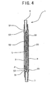
- Fig. 4 is an enlarged sectional view showing the white blood cell-removing device of Fig.1 taken along a line B-B.
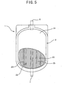
- Fig. 5 shows a state in which a part of the white blood cell-removing device of Fig. 1 has been removed therefrom.
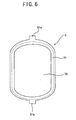
- Fig. 6 shows a white blood cell-removing filter member for use in the white blood cell-removing device of the present invention.
- Fig. 7 is a front view showing a white blood cell-removing device of another embodiment of the present invention as viewed from an outlet side blood chamber thereof.
- Fig. 8 is an enlarged sectional view showing the white blood cell-removing device of Fig. 7 taken along a line C-C.
- Fig. 9 shows a state in which a part of the white blood cell-removing device of Fig. 7 has been removed therefrom.
- Fig. 10 shows a state in which a part of a white blood cell-removing device of another embodiment of the present invention has been removed therefrom.
- Using the embodiments shown in the drawings, the white blood cell-removing device of the present invention will be described below.
- As shown in Figs. 1, 2 and 4, the white blood cell-removing device (leukocyte depleting device) 1 of the present invention has a bag-
shaped housing 2 made of soft resin; a white blood cell-removing filter member (leukocyte depleting filter) 5 partitioning the inside of thehousing 2 into an inletside blood chamber 3 and an outletside blood chamber 4; ablood inlet port 6 positioned at one side of thehousing 2 and communicating with the inletside blood chamber 3; and ablood outlet port 7 positioned at the other side of thehousing 2 and communicating with the outletside blood chamber 4. An unevenness or concave/convex surface having a difference of 0.2 - 2mm between its highest and lowest points is formed on aninner surface 2a of the bag-shaped housing 2. made of soft resin and confronting one surface of the white blood cell-removingfilter member 5 forming the outletside blood chamber 4. - As shown in Figs. 3, 4, and 5, in the white blood cell-removing
device 1 of the embodiment, the bag-shaped housing 2 is made of two thermoplastic softresinous sheets resinous sheet 21 is positioned at the side of the inletside blood chamber 3. Theresinous sheet 22 is positioned at the side of the outletside blood chamber 4. The concave/convex surface having the height of 0.2 - 2mm is formed on theinner surface 2a of theresinous sheet 22. In other words, the concave/convex surface is formed on the surface ofresinous sheet 22 confronting one surface of the white blood cell-removingfilter member 5 forming the outletside blood chamber 4. The reason the concave/convex (unevenness) surface is formed on theinner surface 2a of theresinous sheet 22 is to prevent the white blood cell-removingfilter member 5 and theinner surface 2a of theresinous sheet 22 from contacting closely each other, even in the state in which the white blood cell-removingfilter member 5 presses theinner surface 2a of the bag-shaped housing 2 (inner surface 2a of the resinous sheet 22) made of soft resin. That is, the concave/convex surface is formed to securely obtain a blood duct between the white blood cell-removingfilter member 5 and theinner surface 2a of the housing 2 (inner surface 2a of the resinous sheet 22) and thereby prevent reduction of a filtering speed. - As shown in Figs. 1, 3, and 5, in the white blood cell-removing
device 1 of the embodiment, a plurality ofribs 23 is formed on theinner surface 2a of theresinous sheet 22 such that theribs 23 are substantially parallel with one another and extend from one end of thehousing 2 to the other end thereof. In other words, theribs 23 extends from a blood inlet port side to a blood outlet port side blood or flow direction). Theribs 23 have a function of preventing the white blood cell-removingfilter member 5 and theinner surface 2a of theresinous sheet 22 from contacting each other closely and guiding filtered blood to theblood outlet port 7. - The interval between the
adjacent ribs 23 is preferably 1 - 5mm. Theribs 23 are arranged at substantially equal intervals. When the interval between theadjacent ribs 23 is more than 1mm, it is possible to form a sufficiently large blood duct, which allows a filtering period of time to be short. When the interval between theadjacent ribs 23 is less than 5mm, the concave portion of theinner surface 2a of theresinous sheet 22 is prevented from contacting the white blood cell-removingfilter member 5 closely. Thus, the blood duct can be prevented from being sealed. - The width of each of the
ribs 23 is preferably 0.5 - 1mm. The height (difference between highest and lowest portions) of thelengthwise rib 23 is favorably 0.2 - 2mm and more favorably 0.5 - 1mm. The sectional shape of thelengthwise rib 23 is preferably triangular, semi-circle, and the like. That is, it is preferable that thelengthwise rib 23 becomes narrow toward its front end. - The mode of the
rib 23 is not limited to the above-described one. For example, theribs 23 are not necessarily formed at regular intervals. Further, theribs 23 are not necessarily parallel with one another. Furthermore, theribs 23 are not necessarily linear but may extend curvedly from one end of thehousing 2 to the other end thereof. - Further, as in the case of a white blood cell-removing
device 20 of an embodiment shown in Figs. 7 through 9, a plurality oflengthwise ribs 23 and a plurality ofwidthwise ribs 24 may be so formed on theinner surface 2a of theresinous sheet 22 that thelengthwise ribs 23 extend from one end of thehousing 2 to the other end thereof and thewidthwise ribs 24 intersect with thelengthwise ribs 23 substantially perpendicularly thereto. In this case, the interval between the adjacentlengthwise ribs 23 and that between the adjacentwidthwise ribs 24 are both preferably 1 - 5mm. Preferably, they may be formed at substantially regular intervals. The width of thelengthwise rib 23 and that of thewidthwise rib 24 are both preferably 0.5 - 1mm. The height (difference between highest and lowest portions) of thelengthwise rib 23 is favorably 0.2 - 2mm and more favorably 0.5 - 1mm. - The height (difference between highest and lowest portions) of the
widthwise rib 24 is favorably 0.2 - 1mm and more favorably 0.2 - 0.5mm. Favorably, the height of thewidthwise rib 24 is smaller than that that of thelengthwise rib 23. More specifically, it is preferable that the height of thewidthwise rib 24 is smaller than thelengthwise rib 23 by 0.3mm - 1mm. Preferably, the interval between the adjacentwidthwise ribs 24 is larger than that between the adjacentlengthwise ribs 23. More specifically, it is preferable that the interval between the adjacentwidthwise ribs 24 is larger than that between the adjacentlengthwise ribs 23 by 1 - 2mm. - The concave/convex surface formed on the
inner surface 2a of the bag-shapedhousing 2 made of soft resin and confronting one surface of the white blood cell-removingfilter member 5 forming the outletside blood chamber 4 is not necessarily constructed of the above-described rib. For example, as in the case of a white blood cell-removingdevice 30 of an embodiment shown in Fig. 10, the rib may consist ofmany projections 35 scattered on theinner surface 2a of theresinous sheet 22. In this case, the height (difference between highest and lowest portions) of theprojection 35 is favorably 0.2 - 2mm and more favorably 0.5 - 1mm. The shape of theprojection 35 is favorably conic, polygonal, semi-spherical, and the like. It is most favorable that theprojection 35 is semi-spherical. The area of theprojection 35 is preferably 0.5 - 10mm2. The number of theprojections 35 is preferably 3-50 per 1cm2, although it is varied according to the area of the base of theprojection 35. The distance between theadjacent projections 35 is preferably 1 - 10mm. - In the white blood cell-removing
device 1 of the embodiment, the white blood cell-removingfilter member 5 is formed of a sheet-shapedframe 51 made of thermoplastic soft resin and afiltering part 52 whose peripheral portion is directly or indirectly fixed to the sheet-shapedframe 51 made of thermoplastic soft resin. Thefiltering part 52 is formed of a laminate consisting of a plurality of filtering materials. The white blood cell-removingfilter member 5 has a filtering part formed of thefiltering part 52 and a non-filtering part formed on the entire periphery of thefiltering part 52. The white blood cell-removingfilter member 5 is sandwiched between two thermoplasticsoft resinous sheets frame 51 made of thermoplastic soft resin is thermally fused to the two thermoplasticsoft resinous sheets filter member 5 partitions the space (interior of housing 2) surrounded with the two thermoplasticsoft resinous sheets side blood chamber 3 and the outletside blood chamber 4. - The soft resinous tube constructing the
blood inlet port 6 is thermally fused to a central portion of one end (upper end) of each of the two thermoplasticsoft resinous sheets blood inlet port 6 communicates with the inletside blood chamber 3. An opening at one end of the soft resinous tube is located inside the inletside blood chamber 3. Similarly, the soft resinous tube constructing theblood outlet port 7 is thermally fused to a central portion of the other end (lower end) of each of the two thermoplasticsoft resinous sheets blood outlet port 7 communicates with the outletside blood chamber 4. An opening at the other end of the soft resinous tube is located inside the outletside blood chamber 4. - As shown in Fig. 6, in the white blood cell-removing
device 1 of the embodiment, the sheet-shapedframe 51, made of thermoplastic soft resin, of the white blood cell-removingfilter member 5 has short belt-shapedextended portions 51a and 51b projecting outward from a central portion of one end (upper end) thereof and from a central portion of the other end (lower end) thereof, respectively. The soft resinous tube constituting theblood inlet port 6 is fused to theresinous sheets side resinous sheet 21. The soft resinous tube constituting theblood outlet port 7 is fused to theresinous sheets extended part 51b and the outletside resinous sheet 22. Thereby, theblood inlet port 6 communicates with only the inletside blood chamber 3, whereas theblood outlet port 7 communicates with only the outletside blood chamber 4. - The white blood cell-removing
filter member 5 is fused to the housing 2 (between the two thermoplasticsoft resinous sheets 21 and 22) such that it is located in the region outside the broken line of Fig. 6. Thus, on the peripheral part of the outletside blood chamber 4, the white blood cell-removingdevice 1 has ablood duct 26 formed between the part, of the white blood cell-removingfilter member 5, which does not contact the filtering part 52 (in other words, the part not having a filtering function, namely, the non-filtering part) and one inner surface of thehousing 2. Similarly, on the peripheral part of the inletside blood chamber 3, the white blood cell-removingdevice 1 has ablood duct 27 formed between the part, of the white blood cell-removingfilter member 5, which does not contact the filtering part 52 (in other words, the part not having a filtering function, namely, the non-filtering part) and the other inner surface of thehousing 2. - Because the
blood ducts housing 2 such that theblood ducts housing 2, blood is allowed to flow preferably along the inner peripheral part of thehousing 2 and thus prevented from staying thereon. Further, because theblood ducts blood outlet port 7 inside the outletside blood chamber 4, processed blood flowing along aduct 25 between theadjacent ribs 23 is preferably guided to theblood outlet port 7. Thus, the construction allows the degree of reduction of the filtering speed to be small. It is preferable that the white blood cell-removingdevice 1 contains air more than 5ml. - Flexible thermoplastic resin is used as the material to form the thermoplastic
soft resinous sheets housing 2, the sheet-shapedframe 51 of the white blood cell-removingfilter member 5, theblood inlet port 6, and theblood outlet port 7. More specifically, the following flexible thermoplastic resins can be used: soft vinyl chloride resin (polyvinyl chloride; a copolymer of vinyl chloride and vinyl acetate; a copolymer of vinyl chloride and ethylene; a copolymer of vinyl chloride and vinylidene chloride; a copolymer of polyvinyl chloride and urethane; a copolymer of polyvinyl chloride and acrylonitrile; a copolymer of vinyl chloride and methyl methacrylate, and a modified substance of soft vinyl chloride resin consisting of any one of the above-described polymers and a plasticizer); a hydrogenated copolymer of styrene, butadiene, and styrene; a thermoplastic elastomer such as a copolymer of styrene, butadiene, and styrene or a hydrogenated substance thereof; a mixture of a thermoplastic elastomer and a softening agent such as polyolefin and ethylene-ethyl acrylate; polyurethane (polyester polyurethane, polyether polyurethane); polyolefin (polyethylene; polypropylene; a copolymer of ethylene and propylene; a copolymer of ethylene and vinyl chloride; a mixture of polypropylene and polyethylene or polybutene); polyester (polyethylene terephthalate; polybutylene terephthalate); and polyamide. The following substances are preferably used: soft vinyl chloride resin; a copolymer of styrene, butadiene, and styrene; polyester; a copolymer of styrene, ethylene, butylene, and styrene; and a thermoplastic elastomer containing one or more of these resins as its main component. - As the material to form the
blood inlet port 6 and theblood outlet port 7, hard resin may be used. As the hard resin, hard or semi-hard vinyl chloride, polycarbonate, acrylic resin, styrene resin can be used. - For fixing of the thermoplastic
soft resinous sheets housing 2; the sheet-shapedframe 51, made of thermoplastic soft resin, of the white blood cell-removingfilter member 5; theblood inlet port 6; and theblood outlet port 7, fusing is more favorable than bonding. As fusion welding, an external heating welding by means of heat sealing; and internal welding by means of a high-frequency welder or an ultrasonic welder are used. Welding can be performed by fusing the above-described members simultaneously or in order. - The
filtering part 52 of the white blood cell-removingfilter member 5 is formed of a laminate or pile up consisting of a plurality of filtering materials each made of a porous material or non-woven cloth. More specifically, sixfiltering materials frame 53. The peripheral portion of the outer side of the fusing auxiliary sheet-shapedframe 53 to which the filtering materials have been fused is fused to the inner peripheral portion of the sheet-shapedframe 51 made of thermoplastic soft resin. As the material of the fusing auxiliary sheet-shapedframe 53, the above-described flexible thermoplastic resin can be used. - The porous material for use in the
filtering part 52 means a material having many pores formed in penetration through it in its thickness direction and thus allowing a liquid to permeate therethrough. The following porous materials can be used for the filtering part 52: Natural, synthetic, semi-synthetic, regenerated organic or inorganic fibers; organic or inorganic sponge foam and the like; materials whose pores are formed by elution, sintering, drawing, perforation of pore components; and materials formed by filling organic or inorganic fine particles or fine pieces into a material or connecting them with one another. - As the porous material of the filtering member (filtering material) 52 of the white blood cell-removing
filter member 5, a sponge-shaped polyurethane porous material and a polyvinyl formal porous material are selected from the above-described porous materials. In the case of a porous material whose pore has a large diameter, it is preferable to use a thick one. In the case of a thin porous material whose pore has a large diameter, it is preferable to use a plurality thereof by laminating them one upon another. In the case of a porous material having small-diameter pores, a thin one can be used. By appropriately selecting a diameter and a thickness, it is possible to use any kind of porous materials that allow blood cells to pass therethrough. A porous material having interstices whose average diameter is 5 - 20 µ m is most effective for removing white blood cells. - The diameter of a fiber of the nonwoven cloth for use in the filtering part 52 (filtering material) of the white blood cell-removing
filter member 5 is preferably 0.3 - 20 µm. As the kind of fibers of the nonwoven cloth, synthetic fibers, semi-synthetic fibers such as regenerated cellulose, natural fibers such as cotton, and inorganic fibers are used. Above all, the synthetic fibers can be preferably used. For example, polyester fibers such as polyethylene terephthalate, nylon, polypropylene, polyacrylonitrile, and the like can be preferably used. As the coating material for the filtering material(nonwoven cloth), the following substances can be used: High polymer materials having hydroxyl group such as hydroxyethyl acrylate, hydroxyethyl methacrylate; high polymer materials having basic functional group containing nitrogen such as a copolymer of diethyl aminoethyl (metha) acrylate and hydroxyethyl (metha) acrylate; polyether urethane. It is possible to coat the surface of the nonwoven cloth with a hydrophilic high polymer or anti-thrombus to allow platelets to favorably permeate the nonwoven cloth. - The examples of the white blood cell-removing device of the present invention will be described below.
- As a material to form the housing, a soft polyvinyl chloride sheet having a length of 110mm, a width of 75mm, and a thickness of 0.4mm and a embossed surface was positioned at the blood inlet side of the housing. Another soft polyvinyl chloride sheet having a length of 110mm, a width of 75mn, and a thickness of 0.5mm was positioned at the blood outlet side of the housing, with sectionally approximately triangular ribs each having a height of 0.8mm and a base width of 1mm formed at regular intervals of 2mm on one surface thereof.
- A tube (length: 23mm, outer diameter: 6mm) made of a soft polyvinyl chloride sheet was used to form the blood inlet port and the blood outlet port.
- As the white blood cell-removing filtering material, six polyurethane porous materials (thickness: 1mm, average pore diameter: 5 µm, length: about 85mm, width: about 65mm) were used. Five of the six polyurethane porous materials were fused to a fusing auxiliary sheet-shaped frame. One of the six polyurethane porous material and the auxiliary sheet-shaped frame fused five polyurethane porous materials were fused to a fusing sheet-shaped frame (length: 110mm, width: 75mm, frame width: 10 - 25mm) by heat seal.
- A white blood cell-removing filter member formed of the filtering material fused to the fusing auxiliary sheet-shaped frame was placed on the soft polyvinyl chloride sheet positioned at the blood inlet side of the housing. The tube made of the soft polyvinyl chloride sheet was placed between an extended part of the upper side sheet-shaped frame of the white blood cell-removing filter member and the soft polyvinyl chloride sheet positioned at the blood inlet side of the housing. Then, the soft polyvinyl chloride sheet positioned at the blood outlet side of the housing was placed on the white blood cell-removing filter member such that the rib-formed surface of the soft polyvinyl chloride sheet was located over the surface of the white blood cell-removing filter member. Then, the tube made of the soft polyvinyl chloride sheet was placed between an extended part of the lower side sheet-shaped frame of the white blood cell-removing filter member and the soft polyvinyl chloride sheet positioned at the blood outlet side of the housing. Both tubes and the peripheral portion of the sheet-shaped frame of the white blood cell-removing filter member were thermally fused to both soft polyvinyl chloride sheets by a high-frequency welder to prepare a white blood cell-removing device of the present invention.
- The sheet-shaped frame has an unfused portion having a length of 3mm to form an annular portion not having a filtering function on the periphery of the inside (inlet side blood chamber and outlet side blood chamber) of the white blood cell-removing device.
- A white blood cell-removing device of the present invention was prepared in a manner similar to that of the first example except that ribs approximately triangular in section each and having a height of 0.22mm and a base width of 1mm were formed at regular intervals of 2mm on one surface of the soft polyvinyl chloride sheet having a length of 110mm, a width of 75mm, and a thickness of 0.5mm and positioned at the blood outlet side of the housing.
- A white blood cell-removing device of the present invention was prepared in a manner similar to that of the first example except that 25 projections (par 1cm2) each having a height of 0.8mm and a base area of 1mm2 were formed at intervals of 2mm on one surface of the soft polyvinyl chloride sheet having a length of 110mm, a width of 75mm, and a thickness of 0.5mm and positioned at the blood outlet side of the housing.
- A white blood cell-removing device of the present invention was prepared in a manner similar to that of the first example except that ribs approximately triangular in section each having a height of 0.8mm and a base width of 1mm were formed at regular intervals of 5mm on one surface of the soft polyvinyl chloride sheet having a length of 110mm, a width of 75mm, and a thickness of 0.5mm and positioned at the blood outlet side of the housing.
- A white blood cell-removing device of the present invention was prepared in a manner similar to that of the first example except that ribs approximately triangular in section each having a height of 2.0mm and a base width of 1.5mm were formed at regular intervals of 2mm on one surface of the soft polyvinyl chloride sheet having a length of 110mm, a width of 75mm, and a thickness of 0.5mm and positioned at the blood outlet side of the housing.
- A white blood cell-removing device of the present invention was prepared in a manner similar to that of the first example except that ribs approximately triangular in section each having a height of 0.18mm and a base width of 1mm were formed substantially at regular intervals of 2mm on one surface of the soft polyvinyl chloride sheet having the length of 110mm, the width of 75mm, and the thickness of 0.5mm and positioned at the blood outlet side of the housing.
- A white blood cell-removing device of the present invention was prepared in a manner similar to that of the first example except that ribs approximately triangular in section each having a height of 2.5mm and a base width of 1.5mm were formed substantially at regular intervals of 2mm on one surface of the soft polyvinyl chloride sheet having a length of 110mm, a width of 75mm, and a thickness of 0.5mm and positioned at the blood outlet side of the housing.
- A white blood cell-removing device of the present invention was prepared in a manner similar to that of the first example except that the same soft polyvinyl chloride sheet was used on the blood inlet and outlet sides of the housing; a polyester nonwoven cloth was interposed between the soft polyvinyl chloride sheet at the blood outlet side and the white blood cell-removing filter member; and the peripheral portion of the nonwoven cloth was fused to the soft polyvinyl chloride sheets at the blood inlet side and that at the blood outlet side.
- A white blood cell-removing device of the present invention was prepared in a manner similar to that of the first example except that the same soft polyvinyl chloride sheet was used on the blood inlet and outlet sides of the housing; two tubes (length: 85mm, outer diameter: 4.4mm, inner diameter: 3.0mm) made of soft polyvinyl chloride was sandwiched between the soft polyvinyl chloride sheets at the blood outlet side and the white blood cell-removing filter member such that the two tubes were approximately parallel with a blood flow direction; and in fusing the white blood cell-removing filter member to the upper and lower (blood outlet and inlet sides) soft polyvinyl chloride sheets by a high-frequency welder, the two tubes were also fused to the soft polyvinyl chloride sheets.
- Using the white blood cell-removing devices of the embodiments and the white blood cell-removing devices of the comparison examples, the following experiments were conducted.
- Using a triple bag containing an ACD liquid and a MAP liquid, 400ml of blood was collected. The blood was centrifuged in 18 hours after the blood collection was performed. Blood plasma obtained as a supernatant liquid was put in a transfer bag. Then, the MPA liquid was added to thick red blood cell left in a blood collection bag (donor bag) to obtain MPA-added thick red blood cells. Himac CR7 (Nissei Sangyo Co., Ltd.) was used for the centrifuge. The centrifuge was carried out in the condition of 22°C, 4100rpm, and seven minutes.
- Using a tube sealer, unrequired bags and tubes were cut off to obtain a bag containing the MPA-added thick red blood cell. After the MPA-added thick red blood cell was kept at 4°C for three days, a white blood cell-removing device was connected with the bag to collect white blood cell-removed thick red blood cells. In collecting the white blood cell-removed thick red blood cells, the bag containing the MPA-added thick red blood cells was placed at a higher position, and a bag for collecting the white blood cell-removed thick red blood cells was placed on an electronic balance placed about 1m downward from the bag containing the MPA-added thick red blood cells. The white blood cell-removing device was placed at a location intermediate between both bags to collect the white blood cell-removed thick red blood cells by utilizing the vertical difference in the positions thereof.
- Measurements were made on the period of time for collecting the white blood cell-removed thick red blood cells, the weight of the collected white blood cell-removed thick red blood cells, the number of platelets of the collected white blood cell-removed thick red blood cells, and the number of remaining white blood cells of the collected white blood cell-removed thick red blood cells. As the electronic balance (measurement of weight), BL-3200S manufactured by Shimazu Seisakusho Co., Ltd. was used. As the measuring apparatus, Sysmex NE-6000 manufactured by Toa Iyo Denshi Co., Ltd. was used to measure the number of blood cells and that of platelets. Nageotte method was used to measure a slight amount of white blood cells.
- The result is as shown in tables 1 through 3. Five data was used for each of the measured items. The number of red blood cells, that of platelets, and that of white blood cells shown in the tables 1 through 3 are values converted from measured values supposing that they were present.
- Reference symbols ⊚, ○, Δ, and X in the tables 1 through 3 indicate that evaluation is very favorable, favorable, a permissible range, and unfavorable, respectively.
Table 1 Before filtration Ex.1 Ex. 2 Ex. 3 Liquid amount(ml) 345±12 350±13 343±11 Number of red blood cells (x 1010) 210 ± 19 212±20 209±21 Number of platelets(x 109) 106± 9 98±13 121±11 Number of white blood cells (x 107) 227 ± 22 265±25 210±28 After filtration Ex. 1 Ex. 2 Ex. 3 Liquid amount(ml) 317±11 322±12 316±9 Number of red blood cells(x 1010) 193±19 195±20 192±21 Number of platelets(x 109) 10±2 12±3 9±3 Number of white blood cells (x 104) 5±2 5±3. 5±3 Filtering time (min) 10±2 11±3 18±3 Evaluation Ex. 1 Ex. 2 Ex. 3 Collection percentage of red blood cell ○ ○ ○ Removal percentage of white blood cell ○ ○ ○ Filtering time ⊚ ⊚ Δ Productivity & cost ○ ○ ○ Table 2 Before filtration Ex. 4 Ex. 5 Liquid amount(ml) 347±12 350±13 Number of red blood cells(x 1010) . 211 ± 19 211 ± 20 Number of platelets(x 109) 107±9 98±13 Number of white blood cells (x 107) 226±22 261±25 After filtration Ex. 4 Ex. 5 Liquid amount(ml) 318±11 324±12 Number of red blood cells(x 1010) 198±19 196±20 Number of platelets(x 109) 11 ±2 12±3 Number of white blood cells (x 104) 5±2 5±3 Filtering time (min) 13±2 15±5 Evaluation Ex. 4 Ex. 5 Collection percentage of red blood cell ○ ○ Removal percentage of white blood cell ○ ○ Filtering time ⊚ ○ Productivity & cost ○ ○ Table 3 Before filtration Co. ex.1 Co. ex. 2 Co. ex. 3 Co. ex. 4 Liquid amount (ml) 351 ±16 350±13 344 ± 11 348 ± 13 Number of red blood cells(x 1010) 213±20 212±19 213±18 211 ±20 Number of platelets (x 109) 102±10 107±9 102±11 101±13 Number of white blood cells (x 107) 225±19 261±31 231±19 251±23 After filtration Co. ex.1 Co. ex. 2 Co. ex. 3 Co. ex. 4 Liquid amount(ml) 323±16 314 ± 11 316±9 320 ± 10 Number of red blood cells(x 1010) 196±20 189±19 196±18 194±20 Number of platelets (× 109) 10±3 9±3 8±2 10±3 Number of white blood cells (× 104) 5±3 5±3 5±3 5±3 Filtering time(min) 25±5 12±2 20±10 55±15 Evaluation Co. ex.1 Co. ex. 2 Co. ex. 3 Co. ex. 4 Collection percentage of red blood cell ○ X ○ ○ Removal percentage of white blood cell ○ ○ ○ ○ Filtering time X ⊚ Δ X Productivity & cost ○ ○ X X - In the first comparison example, because the difference between the highest and lowest portions of the rib was small, a sufficient flow speed could not be obtained and thus the filtering period of time took long. In comparison example 2, the difference between the highest and lowest portions of the rib was so large that much blood remained in the dead space. Thus, red blood cell was collected at a low percentage (less than 90%). When the convex portion of the rib is thick, there is much possibility of unfavorable sealing in forming a bag-shaped housing.
- The third comparison example has a problem the nonwoven cloth is expensive, a problem of poor productivity, i.e., much time and labor is required to insert it between the soft polyvinyl chloride sheet and the white blood cell-removing filter member, and a problem that there is a possibility of unfavorable sealing. Similarly to the third comparison example, the fourth comparison example has a problem that the white blood cell-removing device is expensive, a problem of poor productivity, and a problem that a necessary gap cannot be formed. Thus, according to the fourth comparison example, the filtering period of time took long.
Claims (12)
- A white blood cell-removing device (1, 20, 30) comprising:a bag-shaped housing (2) made of soft resin;a white blood cell-removing filter member (5) partitioning an inside of said housing (2) into an inlet side blood chamber (3) and an outlet side blood chamber (4);a blood inlet port (6) positioned at one side of said housing (2) and communicating with said inlet side blood chamber (3); anda blood outlet port (7) positioned at the other side of said housing (2) and communicating with said outlet side blood chamber (4),wherein said white blood cell-removing filter member (5) has a filtering part (52) and a non-filtering part formed on an entire periphery of said filtering part (52); and a blood duct (26) formed between said non-filtering part and an inner surface of said housing (2) is located on an inner peripheral part of said housing (2),
characterized in that an unevenness, surface having a difference of 0.2 - 2mm between highest and lowest portions thereof is formed on an inner surface of said bag-shaped housing (2) made of soft resin and confronting said outlet side blood chamber (4). - A white blood cell-removing device (1, 20, 30) according to claim 1, wherein said unevenness surface is formed of a plurality of ribs (23,24).
- A white blood cell-removing device (1) according to claim 2, wherein said ribs (23) extend from a blood inlet port side to a blood outlet port side.
- A white blood cell-removing device (20) according to claim 2, wherein said ribs (23,24) are spaced at intervals of 1 - 5mm.
- A white blood cell-removing (30) device according to claim 2, wherein said ribs (35) consist of scattered projections.
- A white blood cell-removing device (20) according to claim 1, wherein said unevenness surface is formed of a plurality of lengthwise ribs (23) extending from one end of said housing to the other end thereof and a plurality of widthwise ribs (24) intersecting substantially perpendicularly with said lengthwise ribs (23); and a height of each of said widthwise ribs (24) is smaller than that of each of lengthwise ribs (23).
- A white blood cell-removing device (20) according to claim 6, wherein said lengthwise ribs (23) are spaced at intervals of 1 - 5mm.
- A white blood cell-removing device (20) according to claim 6, wherein said widthwise ribs (24) are spaced at larger intervals than said lengthwise ribs (23).
- A white blood cell-removing device (1, 20, 30) according to claim 1, wherein said filtering part (52) of said white blood cell-removing filter member (5) is formed of a filtering material of a porous material or nonwoven cloth.
- A white blood cell-removing device (1, 20, 30) according to claim 9, wherein said porous material is made of polyurethane.
- A white blood cell-removing device (1, 20, 30) according to claim 9, wherein said nonwoven cloth is made of polyester fibers.
- A white blood cell-removing device (1, 20, 30) according to claim 1, wherein said bag-shaped housing (2) made of soft resin consists of two thermoplastic soft resinous sheets (21,22); said white blood cell-removing filter member (5) consists of a sheet-shaped frame (51) made of thermoplastic soft resin and a filtering material (52) whose peripheral portion is fixed to said sheet-shaped frame (51); said white blood cell-removing filter member (5) is sandwiched between said two thermoplastic soft resinous sheets (21,22); and a peripheral portion of said sheet-shaped frame (51) made of thermoplastic soft resin is thermally fused to said two thermoplastic soft resinous sheets (21,22).
Priority Applications (1)
| Application Number | Priority Date | Filing Date | Title |
|---|---|---|---|
| EP07012962A EP1844799B1 (en) | 1998-05-19 | 1999-05-18 | White blood cell-removing apparatus |
Applications Claiming Priority (3)
| Application Number | Priority Date | Filing Date | Title |
|---|---|---|---|
| JP15523298A JP3758853B2 (en) | 1997-11-28 | 1998-05-19 | Leukocyte remover |
| JP15523298 | 1998-05-19 | ||
| EP99108692A EP0958838B1 (en) | 1998-05-19 | 1999-05-18 | White blood cell-removing method |
Related Parent Applications (1)
| Application Number | Title | Priority Date | Filing Date |
|---|---|---|---|
| EP99108692A Division EP0958838B1 (en) | 1998-05-19 | 1999-05-18 | White blood cell-removing method |
Related Child Applications (1)
| Application Number | Title | Priority Date | Filing Date |
|---|---|---|---|
| EP07012962A Division EP1844799B1 (en) | 1998-05-19 | 1999-05-18 | White blood cell-removing apparatus |
Publications (3)
| Publication Number | Publication Date |
|---|---|
| EP1566189A2 EP1566189A2 (en) | 2005-08-24 |
| EP1566189A3 EP1566189A3 (en) | 2005-10-19 |
| EP1566189B1 true EP1566189B1 (en) | 2007-11-21 |
Family
ID=15601432
Family Applications (3)
| Application Number | Title | Priority Date | Filing Date |
|---|---|---|---|
| EP05010012A Expired - Lifetime EP1566189B1 (en) | 1998-05-19 | 1999-05-18 | White blood cell-removing device |
| EP07012962A Expired - Lifetime EP1844799B1 (en) | 1998-05-19 | 1999-05-18 | White blood cell-removing apparatus |
| EP99108692A Expired - Lifetime EP0958838B1 (en) | 1998-05-19 | 1999-05-18 | White blood cell-removing method |
Family Applications After (2)
| Application Number | Title | Priority Date | Filing Date |
|---|---|---|---|
| EP07012962A Expired - Lifetime EP1844799B1 (en) | 1998-05-19 | 1999-05-18 | White blood cell-removing apparatus |
| EP99108692A Expired - Lifetime EP0958838B1 (en) | 1998-05-19 | 1999-05-18 | White blood cell-removing method |
Country Status (5)
| Country | Link |
|---|---|
| US (1) | US6221264B1 (en) |
| EP (3) | EP1566189B1 (en) |
| DE (2) | DE69926436T2 (en) |
| DK (2) | DK0958838T3 (en) |
| ES (3) | ES2375308T3 (en) |
Families Citing this family (31)
| Publication number | Priority date | Publication date | Assignee | Title |
|---|---|---|---|---|
| US7824343B2 (en) * | 1999-07-29 | 2010-11-02 | Fenwal, Inc. | Method and apparatus for blood sampling |
| EP1377216A2 (en) * | 1999-07-29 | 2004-01-07 | Baxter International Inc. | Sampling tube holder for blood sampling system |
| US6709412B2 (en) | 1999-09-03 | 2004-03-23 | Baxter International Inc. | Blood processing systems and methods that employ an in-line leukofilter mounted in a restraining fixture |
| US7651474B2 (en) | 1999-10-01 | 2010-01-26 | Caridianbct, Inc. | Method and apparatus for leukoreduction of red blood cells |
| AU2002243033B2 (en) * | 2001-04-13 | 2006-02-02 | Asahi Kasei Medical Co., Ltd | Liquid filtering method and filtering system |
| WO2002087660A1 (en) * | 2001-04-26 | 2002-11-07 | Asahi Medical Co., Ltd. | Blood filtration methods and blood filtration apparatus |
| EP1455860B1 (en) | 2001-12-10 | 2011-08-31 | CaridianBCT, Inc. | Method for the leukoreduction of red blood cells |
| CA2474555A1 (en) | 2002-02-01 | 2003-08-07 | Gambro, Inc. | Whole blood collection and processing method |
| US6709868B2 (en) | 2002-05-20 | 2004-03-23 | Portascience Inc. | Method and apparatus for measuring white blood cell count |
| US7033499B2 (en) * | 2003-02-13 | 2006-04-25 | Ilc Dover Lp | Flexible disposable vessel |
| US7431837B2 (en) * | 2003-02-13 | 2008-10-07 | Ilc Dover Lp | Mixing vessel and method of use |
| US7601268B2 (en) * | 2003-05-27 | 2009-10-13 | Haemonetics Corporation | Continuous blood filtration and method of use |
| US20060167401A1 (en) * | 2005-01-21 | 2006-07-27 | National Stem Cell Inc | Apparatus and method for stem cell preservation and usage |
| US20070119780A1 (en) * | 2005-11-28 | 2007-05-31 | Hemerus Medical, Llc | Prechargable fluid filtration method and apparatus |
| US7655146B2 (en) * | 2006-02-20 | 2010-02-02 | Asahi Kasei Medical Co., Ltd. | Method for filtering blood or blood components using leukocyte-removing filter and filter device |
| US20080108845A1 (en) * | 2006-11-07 | 2008-05-08 | Hari Babu Sunkara | Polytrimethylene ether glycol esters |
| GB0809092D0 (en) | 2008-05-20 | 2008-06-25 | Univ Strathclyde | Fluid processing device |
| FR2932989B1 (en) * | 2008-06-27 | 2011-08-26 | Maco Pharma Sa | FILTRATION UNIT HAVING AN APPROPRIATE COMPARTMENT |
| FR2932988B1 (en) * | 2008-06-27 | 2010-09-03 | Maco Pharma Sa | FLUID FILTERING UNIT HAVING JOINT INTERRUPT |
| AU2010320670B2 (en) | 2009-11-17 | 2015-10-29 | Brightwake Limited | Device and method for processing fluid |
| CN102242054B (en) * | 2011-05-11 | 2013-06-05 | 浙江星月生物科技股份有限公司 | Totally-enclosed cell and cell factor preparation device and preparation method thereof |
| CN105592869B (en) * | 2013-10-03 | 2018-09-04 | 旭化成医疗株式会社 | The manufacturing method of blood processing filter and blood processing filter |
| EP3117844B1 (en) * | 2014-03-10 | 2019-06-19 | Asahi Kasei Medical Co., Ltd. | Blood treatment filter |
| US9782707B2 (en) | 2014-03-24 | 2017-10-10 | Fenwal, Inc. | Biological fluid filters having flexible walls and methods for making such filters |
| US10159778B2 (en) | 2014-03-24 | 2018-12-25 | Fenwal, Inc. | Biological fluid filters having flexible walls and methods for making such filters |
| US9968738B2 (en) | 2014-03-24 | 2018-05-15 | Fenwal, Inc. | Biological fluid filters with molded frame and methods for making such filters |
| USD734467S1 (en) | 2014-03-24 | 2015-07-14 | Fenwal, Inc. | Blood filter |
| US10376627B2 (en) | 2014-03-24 | 2019-08-13 | Fenwal, Inc. | Flexible biological fluid filters |
| US9796166B2 (en) | 2014-03-24 | 2017-10-24 | Fenwal, Inc. | Flexible biological fluid filters |
| US20220040392A1 (en) * | 2018-12-25 | 2022-02-10 | Terumo Kabushiki Kaisha | Biological component separation device |
| IT201900009918A1 (en) * | 2019-06-24 | 2020-12-24 | G E A F S P A | WELDING OF A PLASTIC SHEET FOR MEDICAL FILTERING DEVICE |
Family Cites Families (18)
| Publication number | Priority date | Publication date | Assignee | Title |
|---|---|---|---|---|
| FR2048130A5 (en) * | 1969-12-05 | 1971-03-19 | Swank Roy | |
| ATE16350T1 (en) * | 1980-05-20 | 1985-11-15 | Haemonetics Corp | LIQUID SUCTION APPARATUS AND FLEXIBLE LIQUID COLLECTING BAG SUITED FOR USE IN SUCH APPARATUS. |
| JPS5710856A (en) | 1980-06-23 | 1982-01-20 | Nec Corp | Magnetic disk control device |
| US4437472A (en) * | 1981-06-19 | 1984-03-20 | Henry Naftulin | Apparatus for collecting fluids |
| EP0516846A1 (en) * | 1989-06-13 | 1992-12-09 | SAKAMOTO, Atsunobo | Bag-like filter |
| US5180504A (en) | 1991-05-22 | 1993-01-19 | Baxter International Inc. | Systems and methods for removing undesired matter from blood cells |
| FR2677883B1 (en) * | 1991-06-24 | 1997-07-18 | Maco Pharma Sa | FILTER POCKET FOR ALLOWING STERILE BLOOD FILTRATION AND BLOOD COLLECTION POCKET SET. |
| CH686027A5 (en) * | 1991-07-26 | 1995-12-15 | Elp Rochat | Unit of recovery and blood filtration. |
| US5695489A (en) * | 1991-09-30 | 1997-12-09 | Baxter International Inc. | Blood filtering container |
| JP3231086B2 (en) * | 1992-06-30 | 2001-11-19 | テルモ株式会社 | Liquid separation device |
| WO1994001193A1 (en) * | 1992-07-13 | 1994-01-20 | Pall Corporation | Automated system and method for processing biological fluid |
| GB9218581D0 (en) * | 1992-09-02 | 1992-10-14 | Pall Corp | Removal of unwanted fluids from processed blood products |
| EP0591980B1 (en) * | 1992-10-07 | 1999-05-06 | Asahi Medical Co., Ltd. | Leukocyte-removing filter device and system |
| US5527472A (en) * | 1993-06-14 | 1996-06-18 | Baxter International Inc. | Closed systems and methods for removing undesired matter from blood cells |
| AU685573B2 (en) * | 1993-12-22 | 1998-01-22 | Baxter International Inc. | Filtration media and device for filtering leukocytes |
| US5798041A (en) * | 1995-09-06 | 1998-08-25 | Hemasure, Inc. | In-line liquid filtration device useable for blood, blood products or the like |
| FR2718033B1 (en) * | 1994-03-31 | 1998-02-13 | Inoteb | Biological fluid filtration device and its application. |
| CH691219A5 (en) * | 1995-10-26 | 2001-05-31 | Medtronic Electromedics Inc | Disposable filtration flexible bag. |
-
1999
- 1999-05-18 ES ES07012962T patent/ES2375308T3/en not_active Expired - Lifetime
- 1999-05-18 EP EP05010012A patent/EP1566189B1/en not_active Expired - Lifetime
- 1999-05-18 EP EP07012962A patent/EP1844799B1/en not_active Expired - Lifetime
- 1999-05-18 ES ES99108692T patent/ES2243023T3/en not_active Expired - Lifetime
- 1999-05-18 DK DK99108692T patent/DK0958838T3/en active
- 1999-05-18 DK DK05010012T patent/DK1566189T3/en active
- 1999-05-18 EP EP99108692A patent/EP0958838B1/en not_active Expired - Lifetime
- 1999-05-18 ES ES05010012T patent/ES2293415T3/en not_active Expired - Lifetime
- 1999-05-18 DE DE69926436T patent/DE69926436T2/en not_active Expired - Lifetime
- 1999-05-18 DE DE69937616T patent/DE69937616T2/en not_active Expired - Lifetime
- 1999-05-19 US US09/314,082 patent/US6221264B1/en not_active Expired - Lifetime
Also Published As
| Publication number | Publication date |
|---|---|
| EP1566189A2 (en) | 2005-08-24 |
| EP1844799B1 (en) | 2011-10-19 |
| DE69926436T2 (en) | 2006-06-01 |
| DK1566189T3 (en) | 2008-02-04 |
| EP0958838B1 (en) | 2005-08-03 |
| EP0958838A2 (en) | 1999-11-24 |
| US6221264B1 (en) | 2001-04-24 |
| DK0958838T3 (en) | 2005-12-12 |
| EP0958838A3 (en) | 1999-12-15 |
| DE69926436D1 (en) | 2005-09-08 |
| ES2293415T3 (en) | 2008-03-16 |
| ES2243023T3 (en) | 2005-11-16 |
| ES2375308T3 (en) | 2012-02-28 |
| DE69937616D1 (en) | 2008-01-03 |
| DE69937616T2 (en) | 2008-10-23 |
| EP1844799A1 (en) | 2007-10-17 |
| EP1566189A3 (en) | 2005-10-19 |
Similar Documents
| Publication | Publication Date | Title |
|---|---|---|
| EP1566189B1 (en) | White blood cell-removing device | |
| JP5008643B2 (en) | Blood processing circuit | |
| EP0591980B1 (en) | Leukocyte-removing filter device and system | |
| US9421320B2 (en) | Blood processing filter and the method for manufacturing the same | |
| EP2659917B1 (en) | Blood processing filter | |
| US8337700B1 (en) | High capacity biological fluid filtration apparatus | |
| US8763816B2 (en) | Filter for processing blood | |
| AU2007347456B2 (en) | A high capacity biological fluid filtration apparatus | |
| JP3014916B2 (en) | Filter for leukocyte removal | |
| EP2659920B1 (en) | Blood processing filter, and priming method for blood processing filter | |
| JPH07124255A (en) | Leukocyte separation filter and leukocyte remover | |
| EP1309384B1 (en) | Blood treatment filters and blood collection systems | |
| AU2001263488A1 (en) | Improvements in blood filters, blood collection and processing systems, and methods therefor | |
| JP2004520087A (en) | Blood collection system and method using porous membrane elements | |
| EP3723887B1 (en) | Improved filter unit for whole blood and blood derivatives | |
| JP2001149444A (en) | Hard holder for leukocyte remover | |
| JP4302685B2 (en) | Blood processing method | |
| JP2000342680A (en) | White blood corpuscle remover | |
| JP2001276212A (en) | Method and circuit for blood component collection | |
| JP2003290337A (en) | Blood component separation apparatus |
Legal Events
| Date | Code | Title | Description |
|---|---|---|---|
| REG | Reference to a national code |
Ref country code: SE Ref legal event code: TRGR |
|
| PUAI | Public reference made under article 153(3) epc to a published international application that has entered the european phase |
Free format text: ORIGINAL CODE: 0009012 |
|
| 17P | Request for examination filed |
Effective date: 20050509 |
|
| AC | Divisional application: reference to earlier application |
Ref document number: 0958838 Country of ref document: EP Kind code of ref document: P |
|
| AK | Designated contracting states |
Kind code of ref document: A2 Designated state(s): BE DE DK ES FI FR GB IT NL SE |
|
| PUAL | Search report despatched |
Free format text: ORIGINAL CODE: 0009013 |
|
| AK | Designated contracting states |
Kind code of ref document: A3 Designated state(s): BE DE DK ES FI FR GB IT NL SE |
|
| AKX | Designation fees paid |
Designated state(s): BE DE DK ES FI FR GB IT NL SE |
|
| RTI1 | Title (correction) |
Free format text: WHITE BLOOD CELL-REMOVING DEVICE |
|
| GRAP | Despatch of communication of intention to grant a patent |
Free format text: ORIGINAL CODE: EPIDOSNIGR1 |
|
| GRAS | Grant fee paid |
Free format text: ORIGINAL CODE: EPIDOSNIGR3 |
|
| GRAA | (expected) grant |
Free format text: ORIGINAL CODE: 0009210 |
|
| AC | Divisional application: reference to earlier application |
Ref document number: 0958838 Country of ref document: EP Kind code of ref document: P |
|
| AK | Designated contracting states |
Kind code of ref document: B1 Designated state(s): BE DE DK ES FI FR GB IT NL SE |
|
| REG | Reference to a national code |
Ref country code: GB Ref legal event code: FG4D |
|
| REF | Corresponds to: |
Ref document number: 69937616 Country of ref document: DE Date of ref document: 20080103 Kind code of ref document: P |
|
| REG | Reference to a national code |
Ref country code: DK Ref legal event code: T3 |
|
| REG | Reference to a national code |
Ref country code: ES Ref legal event code: FG2A Ref document number: 2293415 Country of ref document: ES Kind code of ref document: T3 |
|
| ET | Fr: translation filed | ||
| PLBE | No opposition filed within time limit |
Free format text: ORIGINAL CODE: 0009261 |
|
| STAA | Information on the status of an ep patent application or granted ep patent |
Free format text: STATUS: NO OPPOSITION FILED WITHIN TIME LIMIT |
|
| 26N | No opposition filed |
Effective date: 20080822 |
|
| PGFP | Annual fee paid to national office [announced via postgrant information from national office to epo] |
Ref country code: NL Payment date: 20120523 Year of fee payment: 14 Ref country code: DK Payment date: 20120510 Year of fee payment: 14 |
|
| PGFP | Annual fee paid to national office [announced via postgrant information from national office to epo] |
Ref country code: BE Payment date: 20120514 Year of fee payment: 14 Ref country code: FI Payment date: 20120510 Year of fee payment: 14 Ref country code: SE Payment date: 20120511 Year of fee payment: 14 |
|
| BERE | Be: lapsed |
Owner name: TERUMO K.K. Effective date: 20130531 |
|
| REG | Reference to a national code |
Ref country code: NL Ref legal event code: V1 Effective date: 20131201 |
|
| REG | Reference to a national code |
Ref country code: SE Ref legal event code: EUG |
|
| PG25 | Lapsed in a contracting state [announced via postgrant information from national office to epo] |
Ref country code: SE Free format text: LAPSE BECAUSE OF NON-PAYMENT OF DUE FEES Effective date: 20130519 |
|
| REG | Reference to a national code |
Ref country code: DK Ref legal event code: EBP Effective date: 20130531 |
|
| PG25 | Lapsed in a contracting state [announced via postgrant information from national office to epo] |
Ref country code: BE Free format text: LAPSE BECAUSE OF NON-PAYMENT OF DUE FEES Effective date: 20130531 Ref country code: FI Free format text: LAPSE BECAUSE OF NON-PAYMENT OF DUE FEES Effective date: 20130518 Ref country code: NL Free format text: LAPSE BECAUSE OF NON-PAYMENT OF DUE FEES Effective date: 20131201 |
|
| PG25 | Lapsed in a contracting state [announced via postgrant information from national office to epo] |
Ref country code: DK Free format text: LAPSE BECAUSE OF NON-PAYMENT OF DUE FEES Effective date: 20130531 |
|
| REG | Reference to a national code |
Ref country code: FR Ref legal event code: PLFP Year of fee payment: 18 |
|
| REG | Reference to a national code |
Ref country code: FR Ref legal event code: PLFP Year of fee payment: 19 |
|
| REG | Reference to a national code |
Ref country code: FR Ref legal event code: PLFP Year of fee payment: 20 |
|
| PGFP | Annual fee paid to national office [announced via postgrant information from national office to epo] |
Ref country code: GB Payment date: 20180329 Year of fee payment: 20 |
|
| PGFP | Annual fee paid to national office [announced via postgrant information from national office to epo] |
Ref country code: DE Payment date: 20180508 Year of fee payment: 20 Ref country code: ES Payment date: 20180605 Year of fee payment: 20 |
|
| PGFP | Annual fee paid to national office [announced via postgrant information from national office to epo] |
Ref country code: FR Payment date: 20180411 Year of fee payment: 20 Ref country code: IT Payment date: 20180522 Year of fee payment: 20 |
|
| REG | Reference to a national code |
Ref country code: DE Ref legal event code: R071 Ref document number: 69937616 Country of ref document: DE |
|
| REG | Reference to a national code |
Ref country code: GB Ref legal event code: PE20 Expiry date: 20190517 |
|
| PG25 | Lapsed in a contracting state [announced via postgrant information from national office to epo] |
Ref country code: GB Free format text: LAPSE BECAUSE OF EXPIRATION OF PROTECTION Effective date: 20190517 |
|
| REG | Reference to a national code |
Ref country code: ES Ref legal event code: FD2A Effective date: 20200805 |
|
| PG25 | Lapsed in a contracting state [announced via postgrant information from national office to epo] |
Ref country code: ES Free format text: LAPSE BECAUSE OF EXPIRATION OF PROTECTION Effective date: 20190519 |