EP1566128A1 - Appareil électroménager à panneaux articulés - Google Patents
Appareil électroménager à panneaux articulés Download PDFInfo
- Publication number
- EP1566128A1 EP1566128A1 EP05290375A EP05290375A EP1566128A1 EP 1566128 A1 EP1566128 A1 EP 1566128A1 EP 05290375 A EP05290375 A EP 05290375A EP 05290375 A EP05290375 A EP 05290375A EP 1566128 A1 EP1566128 A1 EP 1566128A1
- Authority
- EP
- European Patent Office
- Prior art keywords
- control member
- locking member
- domestic appliance
- locking
- stop
- Prior art date
- Legal status (The legal status is an assumption and is not a legal conclusion. Google has not performed a legal analysis and makes no representation as to the accuracy of the status listed.)
- Granted
Links
Images


Classifications
-
- A—HUMAN NECESSITIES
- A47—FURNITURE; DOMESTIC ARTICLES OR APPLIANCES; COFFEE MILLS; SPICE MILLS; SUCTION CLEANERS IN GENERAL
- A47J—KITCHEN EQUIPMENT; COFFEE MILLS; SPICE MILLS; APPARATUS FOR MAKING BEVERAGES
- A47J37/00—Baking; Roasting; Grilling; Frying
- A47J37/06—Roasters; Grills; Sandwich grills
- A47J37/0611—Roasters; Grills; Sandwich grills the food being cooked between two heating plates, e.g. waffle-irons
-
- A—HUMAN NECESSITIES
- A47—FURNITURE; DOMESTIC ARTICLES OR APPLIANCES; COFFEE MILLS; SPICE MILLS; SUCTION CLEANERS IN GENERAL
- A47J—KITCHEN EQUIPMENT; COFFEE MILLS; SPICE MILLS; APPARATUS FOR MAKING BEVERAGES
- A47J36/00—Parts, details or accessories of cooking-vessels
- A47J36/06—Lids or covers for cooking-vessels
- A47J36/10—Lid-locking devices
Definitions
- the present invention relates to an apparatus appliances having two panels hinged together between an open position and a closed position, of the type waffle iron, meat grill, croque-madeleine, appliances sandwich, croque-monsieur, etc.
- the present invention aims at producing a device of aforementioned type having only one lock that can serve not only to maintain both panels in closed position during a cooking operation (when the control member is between its start position of countdown and end count position), but also when he is tidy.
- the apparatus of the aforementioned type comprises a movable locking member between an open position automatic and a manual opening position, cooperating with the control member so that when the organ of command is driven from its countdown start position time to its stop position, when the organ of blocking is in its automatic open position, the control member is movable to its position activation, and when the locking member is in its manual opening position, the control member is movable to a rest position in which the lock is in its lock position.
- the locking member makes it possible to modify the amplitude of the movement of the control member.
- the device can be used for cooking of a food: the user can drive the organ of command to a start time counting position (which corresponds to a cooking time) and once the time elapsed, the control member is in the activation position in which the lock is in the unlocking position allowing the automatic opening of the panels.
- the locking member is in the manual open position, the device can be stored with both panels in closed position: the control member, requested by the drive element stops in its rest position in which the lock is in the locking position now both panels in closed position.
- the apparatus comprises only one only lock that is used as well for the closing of the device when it is stored only for its closure during a cooking operation and its automatic opening at the end of the cooking time.
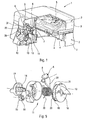
- the device Appliance 1 (in this case a waffle maker) includes two panels 2.
- Each panel 2 includes a shell 3 forming the body of the panel 2, a hob 4 secured to the shell 3 and adapted to receive a food to cook, and an electrical resistance 5 providing the hob 4 the energy needed to achieve the cooking.
- the two panels 2 are articulated to each other by a hinge and are movable between an open position allowing the introduction of a food (in this case the waffle dough) and the withdrawal of this same food once cooked (in this case the waffle), and a closed position allowing the cooking of the food. Both panels 2 are urged towards their open position by a spring torsion disposed at the hinge hinge.
- the appliance also includes a latch 6 which is movable between a locking position and an unlock position.
- the latch 6 holds the two panels 2 in closed position.
- the two panels are driven to their open position under the action of the torsion spring.
- the lock 6 is pivoted about a pivot shaft 7 which extends along a pivot axis 7 and which is carried by one of the two panels (in this case, the panel inferior). In the present embodiments, this axis pivoting is parallel to the axis of the hinge.
- the lock 6 includes, at one of its ends, a hook 8 which is adapted to cooperate with a slot 9 made in the other panel (in this case, the top panel) so that both can be maintained panels 2 in closed position.
- the latch 6 is biased towards its locking position by a torsion spring which is arranged at the level of the pivot shaft 7.
- the appliance 1 also includes a control member 10 which cooperates with the lock 6.
- the control member 10 is part of a timer 11 and is movable between a start time counting position and a stop position. He is asked for his position stopping by a drive element 30 (a spring of twist 30) which is also part of the timer 11.
- control member 10 and the lock 6 are arranged relative to each other so that the organ of command 10 causes the latch 6 in position unlock when the selected time has elapsed.
- control member 10 when the control member 10 is in between countdown end position and a position activation, the lock 6 is driven to its position of unlocking. This end of activation position is between the end of time counting position and the stop position.
- the hook 8 of the lock 6 is shaped so that when the organ of control 10 is in a position allowing the lock 6 to be in its locking position, the hook 8 snap into slot 9 when panels 2 are driven to their closed position.
- control member 10 comprises a manual control button 12.
- control member 10 comprises a surface 13 with which the latch 6 is adapted to come into contact.
- the cam surface 13 is shaped so as to cause the lock 6 (in this case a leg 31 reach by the end of the lock 6 opposite the hook 8) of its locking position at its unlocking position when the control member 10 is driven by its position end of time count at its activation position.
- control member 10 is a rotatably mounted disc around a rotation shaft 14 which extends along an axis of rotation perpendicular to the axis of pivoting.
- manual control knob 12 is integral with the control member and is also mounted rotating around the rotation shaft 14.
- the appliance 1 also includes a damper 15 which is part of the timer 11 and which cooperates with the control member 10.
- the damper 15 is coupled with the body of command 10 when the latter is driven from its position of start of time countdown to its end position of count of time to slow down the movement of the organ of command 10 which is solicited by the element 30.
- the damper 15 is decoupled of the control member 10 when the latter is driven between his end of countdown position until his stopping position, and therefore between its end position of countdown and its activation position.
- the damper 15 is a damper rotating (such as, for example, a rotary damper with grease) comprising a base 16 and a rotary member 17 which is rotatably mounted relative to the base 16 so to be subjected to friction during its rotation.
- a damper rotating such as, for example, a rotary damper with grease
- the element rotating 17 is rotatably coupled to the body of command 10: the rotary element 17 comprises a pinion 18, and the control member 10 comprises a ring gear 19 which comprises a toothed angular sector 20 with which the pinion 18 cooperates by meshing and an angular sector hollowed hollow 21 with which pinion 18 can not enter contact. Pinion 18 is engrained directly with the toothed angular sector 20.
- the damper 15 decreases the rotational speed of the control member 10 so that it corresponds to the indications on the device 1, and when it is driven past this end of counting position of time, the damper 15 is decoupled from the body of command 10 which increases its speed of rotation.
- the time separating the moment when the organ of command 10 is in end counting position and the one where it is in activation position is very short, which allows to have an opening of the device 1 just after the carrying out the cooking.
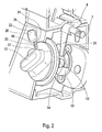
- the appliance 1 also includes a blocking member 22 which cooperates with the body of control 10.
- the locking member 22 is movable between a automatic open position (used during cooking operations) and a manual open position (used for storing the device).
- the amplitude of movement of the control member 10, when he is driven from his countdown start position time to its stop position, is different depending on the position of the blocking member 22.
- the control member 10 When the blocking 22 is in its automatic opening position, the control member 10 is movable to its position activation in which the latch 6 is in its position of unlocking, and when the locking member 22 is in its manual opening position, the control member 10 is movable to a rest position in which the latch 6 is in its locking position.
- the amplitude of movement of the command 10 when it is driven from its starting position time countdown to its stop position, is no longer weak when the locking member 22 is in its position manual opening only when he is in his position automatic opening.
- control member 10 when the locking member 22 is in its automatic opening position, the control member 10 is movable into its activation position (which is also its stop position) and, when the locking member 22 is in its manual open position, the organ of control 10 is movable to its end position of countdown of time (which is also his resting position).
- control member 10 under the action of the element 30, comes into abutment against the body of blocking 22 which is in its manual open position, when he is in his end position of time countdown.
- control member 10 is attached to the manual control knob 12 which includes a obviously 23 which is defined in particular by a surface 24.
- the locking member 22 When the locking member 22 is in its automatic opening position (as shown in 2), the locking member 22 can not come into contact with the manual control knob 12.
- the organ of blocking 22 When the organ of blocking 22 is in its manual open position it is housed in the obviously 23, and under the action of the drive element, the stop surface 24 comes into stop against an abutment surface 25 carried by the body of blocking 22.
- the locking member 22 is stable in its position automatic opening and in its open position manual, and it includes a manual control element 26 allowing the user to maneuver it (in this case the locking member 22 is accessible from the outside and thus forms the manual control element 26).
- the manual control element 26 is slidably mounted along a groove 40 made in the panel carrying the control member 10.
- control member 10 When the user wants to cook a food, after having drive the control member 10 to its starting position time counting, it causes the locking member 22 in its automatic opening position. So once the elapsed cooking time, the control member 10 passes successively at its end of counting position and then at its activation position where the latch 6 is in its position unlocking.
- the control member 10 When the user wants to store the cooking appliance, it drives the control member 10 initially in activation position at least to its position of end of countdown and blocking member 22 into its manual open position.
- the organ of command 10 is immobilized in its end position of time count in which the lock 6 is in its lock position. It only remains to close the top panel on the bottom panel.
- the control member 10 When the user wants to use the device 1 (released of its storage), it is enough to train the organ of blocking 22 in its automatic opening position, the control member 10, under the action of the element 30, passes from its end position countdown activation position, which leads to the opening of two panels 2.
- the manual control knob 12 includes a second cam surface 27 with which the locking member 22 is adapted to come into contact.
- the second cam surface 27 is shaped so as to cause the locking member 22 from its manual open position to its position automatic opening when the control member 10 is driven from its rest position (its end position of countdown) to its start counting position time.
- the stop surface 24 forms one of the ends of the second cam surface 27.
- the range of motion of the command 10 when it is driven from its starting position time countdown to its stop position, is no longer important when the locking member 22 is in its manual open position only when he is in his automatic opening position.
- the locking member 22 is in its position automatic opening, the control member 10 is movable up to its activation position, and, when the organ of blocking 22 is in its manual open position, the control member 10 is movable to its position stop (which is also his rest position).
- the locking member 10 When the locking member 10 is in its position automatic opening, it receives in abutment an element of stop 28 when the control member 10, requested by the training element, arrives in its position activation.
- the organ of blocking 22 is biased towards its open position automatic.
- stop element 28 (in this case a pin 28) is fixed to the control member 10 while the locking member 22 (in this case a blade 22 elastically deformable) is worn by the panel the control member 10.
- the locking member 22 When the locking member 22 (the blade 22) is in its natural position (its automatic open position), it receives in abutment the abutment element 28 (the lug 28) when the control member 10 moves from its starting position time counting at its activation position.
- the organ 22 is rigid enough not to pass in its manual open position despite the energy that it receives when putting in abutment the element of stop 28 against him (due to the training of the organ of control 10 by the training element 30).
- the stop element 28 is adapted to cause the locking member 22 to its position manual opening when the control member 10 is driven from its activation position to its position stopping by a predetermined energy which is greater than that received by the locking member 22 during the setting stop of the abutment element 28 under the solicitation of the training element 30.
- the spigot 28 is adapted to elastically deform the blade 22 until no longer in contact with her and that the organ of control 10 is in a position between the position activation and stop position.
- control member 10 is shaped so that when he is in a position beyond his activation position, the latch 6 is in its position of locking.
- the control member 10 When the user wants to cook a food, he leads the control member 10 from its activation position to its countdown start position. Once the time cooking time, the stop element 28 carried by the organ control unit 10 abuts against the blade 22 (without the move to its manual open position) in its activation position where the latch 6 is in its position unlocking.
- the control member 10 When the user wants to store the device 1, he causes the control member 10 initially in position activation to its stop position, imposing, by through the manual control knob 12, a deformation at the blocking member 22 until the stop element 28 exceeds this hard point. Once this point past, the training element causes the body of control 10 to its stop position in which the lock 6 is in its locking position. He ... not remains to close the top panel on the lower panel.
- the organ order 10 comprises a complementary surface of cam 29 with which the lock 6 is adapted to come into contact.
- the complementary cam surface 29 is shaped in order to cause the lock 6 (in this case the end of the latch 6 opposite the hook 8) of its locking position at its unlocking position when the control member 10 is driven by its position stop at its activation position.
- the complementary cam surface 29 extends the cam surface 13 so that the lock 6 does not bump against any element when the control member 10 passes the activation position in one sense as in the other.
Landscapes
- Engineering & Computer Science (AREA)
- Food Science & Technology (AREA)
- Baking, Grill, Roasting (AREA)
- Cookers (AREA)
- Washing And Drying Of Tableware (AREA)
- Operating, Guiding And Securing Of Roll- Type Closing Members (AREA)
- Combinations Of Kitchen Furniture (AREA)
- Food-Manufacturing Devices (AREA)
- Nozzles (AREA)
- Surgical Instruments (AREA)
- Joints Allowing Movement (AREA)
- Massaging Devices (AREA)
Abstract
Description
- deux panneaux articulés entre eux entre une position ouverte et une position fermée et sollicités vers leur position ouverte,
- un verrou mobile entre une position de verrouillage dans laquelle il maintient les panneaux en position fermée, et une position de déverrouillage, et
- un organe de commande mobile entre une position de début de décompte de temps et une position d'arrêt, sollicité vers sa position d'arrêt par un élément d'entraínement, et coopérant avec le verrou de sorte que, quand l'organe de commande est entre sa position de début de décompte de temps et une position de fin de décompte de temps située entre la position de début de décompte de temps et la position d'arrêt, le verrou est dans sa position de verrouillage, et quand l'organe de commande est entre sa position de fin de décompte de temps et une position d'activation située entre la position de fin de décompte de temps et la position d'arrêt, le verrou est entraíné vers sa position de déverrouillage.
- d'utiliser un organe de blocage stable dans sa position d'ouverture automatique et dans sa position d'ouverture manuelle (tel que celui utilisé dans le premier mode de réalisation) ; l'organe de blocage pourrait alors comprendre un élément de commande manuelle permettant de le manoeuvrer ; de même l'organe de commande pourrait comprendre une deuxième surface de came permettant d'entraíner l'organe de blocage de sa position d'ouverture manuelle à sa position d'ouverture automatique quand l'organe de commande est entraíné de sa position de repos vers sa position de début de décompte de temps.
- d'utiliser, comme organe de blocage, un bouton qui serait monté coulissant le long d'une rainure réalisée dans le panneau sur lequel est monté l'organe de commande, et qui serait sollicité dans sa position d'ouverture automatique par un moyen de rappel (tel q'un ressort) suffisamment résistant pour empêcher que le bouton passe dans sa position d'ouverture manuelle suite à l'énergie reçue lors de la mise en butée de l'élément de butée.
- que l'organe de blocage (par exemple une lame déformable ou un bouton) soit fixé à l'organe de commande, l'élément de butée étant alors porté par le panneau portant l'organe de commande.
Claims (17)
- Appareil électroménager (1) comprenant :caractérisé en ce qu'il comprend un organe de blocage (22) mobile entre une position d'ouverture automatique et une position d'ouverture manuelle, coopérant avec l'organe de commande (10) de sorte que, quand l'organe de commande (10) est entraíné de sa position de début de décompte de temps vers sa position d'arrêt, lorsque l'organe de blocage (22) est dans sa position d'ouverture automatique, l'organe de commande (10) est mobile jusqu'à sa position d'activation, et lorsque l'organe de blocage (22) est dans sa position d'ouverture manuelle, l'organe de commande (10) est mobile jusqu'à une position de repos dans laquelle le verrou (6) est dans sa position de verrouillage.deux panneaux (2) articulés entre eux entre une position ouverte et une position fermée et naturellement sollicités vers leur position ouverte,un verrou (6) mobile entre une position de déverrouillage et une position de verrouillage dans laquelle le verrou (6) maintient les panneaux (2) en position fermée, etun organe de commande (10) mobile entre une position de début de décompte de temps et une position d'arrêt, naturellement sollicité vers sa position d'arrêt par un élément d'entraínement (30), et coopérant avec le verrou (6) de sorte que, quand l'organe de commande (10) est entre sa position de début de décompte de temps et une position de fin de décompte de temps qui est située entre la position de début de décompte de temps et la position d'arrêt, le verrou (6) est dans sa position de verrouillage, et quand l'organe de commande (10) est entre sa position de fin de décompte de temps et une position d'activation qui est située entre la position de fin de décompte de temps et la position d'arrêt, le verrou (6) est entraíné vers sa position de déverrouillage,
- Appareil électroménager (1) selon l'une des revendication 1, caractérisé en ce que l'organe de commande (10) comprend une surface de came (13) avec laquelle le verrou (6) est adapté à venir en contact, la surface de came (13) étant conformée de façon à entraíner le verrou (6) de sa position de verrouillage à sa position de déverrouillage quand l'organe de commande (10) est entraíné de sa position de fin de décompte de temps à sa position d'activation.
- Appareil électroménager (1) selon la revendication 1 ou 2, caractérisé en ce que l'organe de blocage (22) est stable dans sa position d'ouverture automatique et dans sa position d'ouverture manuelle.
- Appareil électroménager (1) selon la revendication 3, caractérisé en ce que l'organe de blocage (22) comprend un élément de commande manuelle (26) permettant de le manoeuvrer.
- Appareil électroménager (1) selon l'une des revendications 1 à 4, caractérisé en ce que l'organe de commande (10) comprend une deuxième surface de came (27) avec laquelle l'organe de blocage (22) est adapté à venir en contact, la deuxième surface de came (27) étant conformée de façon à entraíner l'organe de blocage (22) de sa position d'ouverture manuelle à sa position d'ouverture automatique quand l'organe de commande (10) est entraíné de sa position de repos vers sa position de début de décompte de temps.
- Appareil électroménager (1) selon la revendication 5 caractérisé en ce qu'une extrémité de la deuxième surface de came (27) forme une surface d'arrêt (24) venant en contact avec l'organe de blocage (22) en position d'ouverture manuelle quand l'organe de commande (10) est en position de repos.
- Appareil électroménager (1) selon la revendication 1 ou 2, caractérisé en ce que l'organe de blocage (22) est sollicité vers sa position d'ouverture automatique.
- Appareil électroménager (1) selon l'une des revendications 1 à 7, caractérisé en ce que l'organe de blocage (22) est monté coulissant le long d'une rainure réalisée dans le panneau (2) sur lequel est monté l'organe de commande (10).
- Appareil électroménager (1) selon la revendication 7, caractérisé en ce que l'organe de blocage (22) est une lame (22) déformable élastiquement.
- Appareil électroménager (1) selon la revendication 3 ou l'une des revendications qui en dépend, caractérisé en ce que, quand l'organe de blocage (22) est dans sa position d'ouverture automatique, l'organe de commande (10) est mobile jusque dans sa position d'activation qui est sa position d'arrêt, et, quand l'organe de blocage (22) est dans sa position d'ouverture manuelle, l'organe de commande (10) est mobile jusque dans sa position de repos qui est sa position de fin de décompte de temps.
- Appareil électroménager (1) selon la revendication 10, caractérisé en ce que, quand l'organe de blocage (22) est dans sa position d'ouverture manuelle, il reçoit en butée l'organe de commande (10) quand ce dernier est dans sa position de fin de décompte de temps.
- Appareil électroménager (1) selon l'une des revendications 1 à 9, caractérisé en ce que, quand l'organe de blocage (22) est dans sa position d'ouverture automatique, l'organe de commande (10) est mobile jusque dans sa position d'activation, et, quand l'organe de blocage (22) est dans sa position d'ouverture manuelle, l'organe de commande (10) est mobile jusque dans sa position de repos qui est sa position d'arrêt.
- Appareil électroménager (1) selon la revendication 12, caractérisé en ce que, quand l'organe de blocage (22) est dans sa position d'ouverture automatique, il reçoit en butée un élément de butée (28) quand l'organe de commande (10) est dans sa position d'activation.
- Appareil électroménager (1) selon la revendication 13, caractérisé en ce que l'élément de butée (28) est adapté à entraíner l'organe de blocage (22) vers sa position d'ouverture manuelle quand l'organe de commande (10) est entraíné de sa position d'activation vers sa position d'arrêt par une énergie prédéterminée qui est supérieure à celle reçue par l'organe de blocage (22) quand l'organe de commande (10), sollicité par l'élément d'entraínement (30), vient en butée dans sa position d'activation.
- Appareil électroménager (1) selon la revendication 13 ou 14, caractérisé en ce que l'élément de butée (28) est fixé à l'organe de commande (10), l'organe de blocage (22) étant porté au panneau portant l'organe de commande (10).
- Appareil électroménager (1) selon l'une des revendications 12 à 15, caractérisé en ce que l'organe de commande (10) comprend une surface complémentaire de came (29) avec laquelle le verrou (6) est adapté à venir en contact, et qui est conformée de façon à entraíner le verrou (6) de sa position de verrouillage à sa position de déverrouillage quand l'organe de commande (10) est entraíné de sa position d'arrêt vers sa position d'activation.
- Appareil électroménager (1) selon la revendication 16, caractérisé en ce que la surface complémentaire de came (29) prolonge la surface de came (13) au-delà de la position d'activation, vers la position d'arrêt.
Applications Claiming Priority (2)
| Application Number | Priority Date | Filing Date | Title |
|---|---|---|---|
| FR0401782 | 2004-02-23 | ||
| FR0401782A FR2866540B1 (fr) | 2004-02-23 | 2004-02-23 | Appareil electromenager a panneaux articules |
Publications (2)
| Publication Number | Publication Date |
|---|---|
| EP1566128A1 true EP1566128A1 (fr) | 2005-08-24 |
| EP1566128B1 EP1566128B1 (fr) | 2006-10-11 |
Family
ID=34708015
Family Applications (1)
| Application Number | Title | Priority Date | Filing Date |
|---|---|---|---|
| EP05290375A Expired - Lifetime EP1566128B1 (fr) | 2004-02-23 | 2005-02-18 | Appareil électroménager à panneaux articulés |
Country Status (4)
| Country | Link |
|---|---|
| EP (1) | EP1566128B1 (fr) |
| AT (1) | ATE341983T1 (fr) |
| DE (1) | DE602005000164T2 (fr) |
| FR (1) | FR2866540B1 (fr) |
Families Citing this family (1)
| Publication number | Priority date | Publication date | Assignee | Title |
|---|---|---|---|---|
| CN109528012A (zh) * | 2018-11-26 | 2019-03-29 | 珠海格力电器股份有限公司 | 一种具有检测元件的面板开合装置、控制方法及烹饪器具 |
Citations (5)
| Publication number | Priority date | Publication date | Assignee | Title |
|---|---|---|---|---|
| US3180157A (en) * | 1960-09-19 | 1965-04-27 | John L Harris | Control device |
| US5419305A (en) * | 1993-09-02 | 1995-05-30 | Hanley; Roger T. | Automatic bimetal safety latch for self-cleaning oven doors |
| EP0787453A1 (fr) * | 1996-01-30 | 1997-08-06 | Vicente Gil Garcia | Dispositif pour la fermeture et l'ouverture automatique du couvercle d'un instrument de cuisson, en particulier grill, ou équivalent |
| FR2790932A1 (fr) * | 1999-03-17 | 2000-09-22 | Seb Sa | Appareil electrique du type gaufrier a ouverture automatique |
| WO2002024043A1 (fr) * | 2000-09-19 | 2002-03-28 | Seb Sa | Appareil de cuisson multifonction du type a charniere a ouverture automatique |
-
2004
- 2004-02-23 FR FR0401782A patent/FR2866540B1/fr not_active Expired - Fee Related
-
2005
- 2005-02-18 EP EP05290375A patent/EP1566128B1/fr not_active Expired - Lifetime
- 2005-02-18 DE DE602005000164T patent/DE602005000164T2/de not_active Expired - Lifetime
- 2005-02-18 AT AT05290375T patent/ATE341983T1/de not_active IP Right Cessation
Patent Citations (5)
| Publication number | Priority date | Publication date | Assignee | Title |
|---|---|---|---|---|
| US3180157A (en) * | 1960-09-19 | 1965-04-27 | John L Harris | Control device |
| US5419305A (en) * | 1993-09-02 | 1995-05-30 | Hanley; Roger T. | Automatic bimetal safety latch for self-cleaning oven doors |
| EP0787453A1 (fr) * | 1996-01-30 | 1997-08-06 | Vicente Gil Garcia | Dispositif pour la fermeture et l'ouverture automatique du couvercle d'un instrument de cuisson, en particulier grill, ou équivalent |
| FR2790932A1 (fr) * | 1999-03-17 | 2000-09-22 | Seb Sa | Appareil electrique du type gaufrier a ouverture automatique |
| WO2002024043A1 (fr) * | 2000-09-19 | 2002-03-28 | Seb Sa | Appareil de cuisson multifonction du type a charniere a ouverture automatique |
Also Published As
| Publication number | Publication date |
|---|---|
| FR2866540B1 (fr) | 2006-05-26 |
| FR2866540A1 (fr) | 2005-08-26 |
| EP1566128B1 (fr) | 2006-10-11 |
| ATE341983T1 (de) | 2006-11-15 |
| DE602005000164T2 (de) | 2007-09-06 |
| DE602005000164D1 (de) | 2006-11-23 |
Similar Documents
| Publication | Publication Date | Title |
|---|---|---|
| EP1317201B1 (fr) | Appareil culinaire a plaque de cuisson amovible par dispositif de blocage et deblocage | |
| CA2644909C (fr) | Dispositif de prehension amovible avec moyens d'ouverture des organes formant pince | |
| EP1491122B1 (fr) | Appareil électroménager | |
| WO2011128577A2 (fr) | Appareil de cuisson d'aliments sous pression pourvu d'une piece de transmission mobile | |
| EP1525833A1 (fr) | Grille-pain | |
| EP1318742A1 (fr) | Appareil de cuisson multifonction du type a charniere a ouverture automatique | |
| EP1130990A1 (fr) | Mecanisme de fixation d'un couvercle solidaire du moteur d'un robot menager sur un recipient de travail | |
| EP1566128B1 (fr) | Appareil électroménager à panneaux articulés | |
| EP2172142B1 (fr) | Procédé de commande en déplacement d'un organe mobile d'un bandeau de commande d'un appareil électroménager et appareil électroménager associé | |
| EP1734851A1 (fr) | Appareil electrique de chauffage de liquide | |
| EP1161168B1 (fr) | Appareil electrique du type gaufrier a ouverture automatique | |
| FR2932075A1 (fr) | Appareil de cuisson du type gaufrier a double position d'ouverture | |
| EP2130468A1 (fr) | Appareil de cuisson du type gaufrier à double position d'ouverture | |
| EP1795642B1 (fr) | Bandeau de commande pour appareil électroménager | |
| EP0792608B1 (fr) | Charnière pour plaques électriques et appareil de cuisson à charnière | |
| EP3523488B1 (fr) | Dispositif de commande de chasse d'eau comprenant un organe selecteur rotatif | |
| FR2528096A1 (fr) | Serrure de portiere, notamment pour vehicule automobile, comportant un pene pivotant associe a un dispositif moteur | |
| EP1839544A1 (fr) | Grille-pain | |
| FR2730796A1 (fr) | Appareil de cuisson muni d'un element chauffant mobile | |
| EP0309435B1 (fr) | Appareil de cuisson électrique | |
| EP1321717B1 (fr) | Dispositif de dégagement pour un habillage de porte pivotante | |
| FR2855034A1 (fr) | Appareil electromenager comprenant deux plaques de cuisson a articulation decalee | |
| EP0728891A1 (fr) | Charnière pour une porte montée pivotante | |
| FR2549620A1 (fr) | Programmateur electromecanique | |
| FR2937667A1 (fr) | Commande d'ouverture exterieure pour porte de vehicule automobile |
Legal Events
| Date | Code | Title | Description |
|---|---|---|---|
| PUAI | Public reference made under article 153(3) epc to a published international application that has entered the european phase |
Free format text: ORIGINAL CODE: 0009012 |
|
| AK | Designated contracting states |
Kind code of ref document: A1 Designated state(s): AT BE BG CH CY CZ DE DK EE ES FI FR GB GR HU IE IS IT LI LT LU MC NL PL PT RO SE SI SK TR |
|
| AX | Request for extension of the european patent |
Extension state: AL BA HR LV MK YU |
|
| 17P | Request for examination filed |
Effective date: 20060128 |
|
| GRAC | Information related to communication of intention to grant a patent modified |
Free format text: ORIGINAL CODE: EPIDOSCIGR1 |
|
| GRAP | Despatch of communication of intention to grant a patent |
Free format text: ORIGINAL CODE: EPIDOSNIGR1 |
|
| AKX | Designation fees paid |
Designated state(s): AT BE BG CH CY CZ DE DK EE ES FI FR GB GR HU IE IS IT LI LT LU MC NL PL PT RO SE SI SK TR |
|
| GRAS | Grant fee paid |
Free format text: ORIGINAL CODE: EPIDOSNIGR3 |
|
| GRAA | (expected) grant |
Free format text: ORIGINAL CODE: 0009210 |
|
| AK | Designated contracting states |
Kind code of ref document: B1 Designated state(s): AT BE BG CH CY CZ DE DK EE ES FI FR GB GR HU IE IS IT LI LT LU MC NL PL PT RO SE SI SK TR |
|
| PG25 | Lapsed in a contracting state [announced via postgrant information from national office to epo] |
Ref country code: IT Free format text: LAPSE BECAUSE OF FAILURE TO SUBMIT A TRANSLATION OF THE DESCRIPTION OR TO PAY THE FEE WITHIN THE PRESCRIBED TIME-LIMIT;WARNING: LAPSES OF ITALIAN PATENTS WITH EFFECTIVE DATE BEFORE 2007 MAY HAVE OCCURRED AT ANY TIME BEFORE 2007. THE CORRECT EFFECTIVE DATE MAY BE DIFFERENT FROM THE ONE RECORDED. Effective date: 20061011 Ref country code: IE Free format text: LAPSE BECAUSE OF FAILURE TO SUBMIT A TRANSLATION OF THE DESCRIPTION OR TO PAY THE FEE WITHIN THE PRESCRIBED TIME-LIMIT Effective date: 20061011 Ref country code: FI Free format text: LAPSE BECAUSE OF FAILURE TO SUBMIT A TRANSLATION OF THE DESCRIPTION OR TO PAY THE FEE WITHIN THE PRESCRIBED TIME-LIMIT Effective date: 20061011 Ref country code: LT Free format text: LAPSE BECAUSE OF FAILURE TO SUBMIT A TRANSLATION OF THE DESCRIPTION OR TO PAY THE FEE WITHIN THE PRESCRIBED TIME-LIMIT Effective date: 20061011 Ref country code: NL Free format text: LAPSE BECAUSE OF FAILURE TO SUBMIT A TRANSLATION OF THE DESCRIPTION OR TO PAY THE FEE WITHIN THE PRESCRIBED TIME-LIMIT Effective date: 20061011 Ref country code: AT Free format text: LAPSE BECAUSE OF FAILURE TO SUBMIT A TRANSLATION OF THE DESCRIPTION OR TO PAY THE FEE WITHIN THE PRESCRIBED TIME-LIMIT Effective date: 20061011 Ref country code: PL Free format text: LAPSE BECAUSE OF FAILURE TO SUBMIT A TRANSLATION OF THE DESCRIPTION OR TO PAY THE FEE WITHIN THE PRESCRIBED TIME-LIMIT Effective date: 20061011 Ref country code: SI Free format text: LAPSE BECAUSE OF FAILURE TO SUBMIT A TRANSLATION OF THE DESCRIPTION OR TO PAY THE FEE WITHIN THE PRESCRIBED TIME-LIMIT Effective date: 20061011 Ref country code: SK Free format text: LAPSE BECAUSE OF FAILURE TO SUBMIT A TRANSLATION OF THE DESCRIPTION OR TO PAY THE FEE WITHIN THE PRESCRIBED TIME-LIMIT Effective date: 20061011 Ref country code: RO Free format text: LAPSE BECAUSE OF FAILURE TO SUBMIT A TRANSLATION OF THE DESCRIPTION OR TO PAY THE FEE WITHIN THE PRESCRIBED TIME-LIMIT Effective date: 20061011 Ref country code: CZ Free format text: LAPSE BECAUSE OF FAILURE TO SUBMIT A TRANSLATION OF THE DESCRIPTION OR TO PAY THE FEE WITHIN THE PRESCRIBED TIME-LIMIT Effective date: 20061011 |
|
| REG | Reference to a national code |
Ref country code: GB Ref legal event code: FG4D Free format text: NOT ENGLISH |
|
| REG | Reference to a national code |
Ref country code: CH Ref legal event code: EP |
|
| REG | Reference to a national code |
Ref country code: IE Ref legal event code: FG4D Free format text: LANGUAGE OF EP DOCUMENT: FRENCH |
|
| REF | Corresponds to: |
Ref document number: 602005000164 Country of ref document: DE Date of ref document: 20061123 Kind code of ref document: P |
|
| PG25 | Lapsed in a contracting state [announced via postgrant information from national office to epo] |
Ref country code: SE Free format text: LAPSE BECAUSE OF FAILURE TO SUBMIT A TRANSLATION OF THE DESCRIPTION OR TO PAY THE FEE WITHIN THE PRESCRIBED TIME-LIMIT Effective date: 20070111 Ref country code: DK Free format text: LAPSE BECAUSE OF FAILURE TO SUBMIT A TRANSLATION OF THE DESCRIPTION OR TO PAY THE FEE WITHIN THE PRESCRIBED TIME-LIMIT Effective date: 20070111 Ref country code: BG Free format text: LAPSE BECAUSE OF FAILURE TO SUBMIT A TRANSLATION OF THE DESCRIPTION OR TO PAY THE FEE WITHIN THE PRESCRIBED TIME-LIMIT Effective date: 20070111 |
|
| PG25 | Lapsed in a contracting state [announced via postgrant information from national office to epo] |
Ref country code: ES Free format text: LAPSE BECAUSE OF FAILURE TO SUBMIT A TRANSLATION OF THE DESCRIPTION OR TO PAY THE FEE WITHIN THE PRESCRIBED TIME-LIMIT Effective date: 20070122 |
|
| PG25 | Lapsed in a contracting state [announced via postgrant information from national office to epo] |
Ref country code: IS Free format text: LAPSE BECAUSE OF FAILURE TO SUBMIT A TRANSLATION OF THE DESCRIPTION OR TO PAY THE FEE WITHIN THE PRESCRIBED TIME-LIMIT Effective date: 20070211 |
|
| PG25 | Lapsed in a contracting state [announced via postgrant information from national office to epo] |
Ref country code: MC Free format text: LAPSE BECAUSE OF NON-PAYMENT OF DUE FEES Effective date: 20070228 |
|
| PG25 | Lapsed in a contracting state [announced via postgrant information from national office to epo] |
Ref country code: PT Free format text: LAPSE BECAUSE OF FAILURE TO SUBMIT A TRANSLATION OF THE DESCRIPTION OR TO PAY THE FEE WITHIN THE PRESCRIBED TIME-LIMIT Effective date: 20070319 |
|
| NLV1 | Nl: lapsed or annulled due to failure to fulfill the requirements of art. 29p and 29m of the patents act | ||
| GBV | Gb: ep patent (uk) treated as always having been void in accordance with gb section 77(7)/1977 [no translation filed] |
Effective date: 20061011 |
|
| REG | Reference to a national code |
Ref country code: IE Ref legal event code: FD4D |
|
| PLBE | No opposition filed within time limit |
Free format text: ORIGINAL CODE: 0009261 |
|
| STAA | Information on the status of an ep patent application or granted ep patent |
Free format text: STATUS: NO OPPOSITION FILED WITHIN TIME LIMIT |
|
| 26N | No opposition filed |
Effective date: 20070712 |
|
| PG25 | Lapsed in a contracting state [announced via postgrant information from national office to epo] |
Ref country code: GB Free format text: LAPSE BECAUSE OF FAILURE TO SUBMIT A TRANSLATION OF THE DESCRIPTION OR TO PAY THE FEE WITHIN THE PRESCRIBED TIME-LIMIT Effective date: 20061011 |
|
| PG25 | Lapsed in a contracting state [announced via postgrant information from national office to epo] |
Ref country code: GR Free format text: LAPSE BECAUSE OF FAILURE TO SUBMIT A TRANSLATION OF THE DESCRIPTION OR TO PAY THE FEE WITHIN THE PRESCRIBED TIME-LIMIT Effective date: 20070112 |
|
| PG25 | Lapsed in a contracting state [announced via postgrant information from national office to epo] |
Ref country code: EE Free format text: LAPSE BECAUSE OF FAILURE TO SUBMIT A TRANSLATION OF THE DESCRIPTION OR TO PAY THE FEE WITHIN THE PRESCRIBED TIME-LIMIT Effective date: 20061011 |
|
| PG25 | Lapsed in a contracting state [announced via postgrant information from national office to epo] |
Ref country code: CY Free format text: LAPSE BECAUSE OF FAILURE TO SUBMIT A TRANSLATION OF THE DESCRIPTION OR TO PAY THE FEE WITHIN THE PRESCRIBED TIME-LIMIT Effective date: 20061011 Ref country code: LU Free format text: LAPSE BECAUSE OF NON-PAYMENT OF DUE FEES Effective date: 20070218 |
|
| PG25 | Lapsed in a contracting state [announced via postgrant information from national office to epo] |
Ref country code: HU Free format text: LAPSE BECAUSE OF FAILURE TO SUBMIT A TRANSLATION OF THE DESCRIPTION OR TO PAY THE FEE WITHIN THE PRESCRIBED TIME-LIMIT Effective date: 20070412 Ref country code: TR Free format text: LAPSE BECAUSE OF FAILURE TO SUBMIT A TRANSLATION OF THE DESCRIPTION OR TO PAY THE FEE WITHIN THE PRESCRIBED TIME-LIMIT Effective date: 20061011 |
|
| REG | Reference to a national code |
Ref country code: CH Ref legal event code: PL |
|
| PG25 | Lapsed in a contracting state [announced via postgrant information from national office to epo] |
Ref country code: LI Free format text: LAPSE BECAUSE OF NON-PAYMENT OF DUE FEES Effective date: 20090228 Ref country code: CH Free format text: LAPSE BECAUSE OF NON-PAYMENT OF DUE FEES Effective date: 20090228 |
|
| PGFP | Annual fee paid to national office [announced via postgrant information from national office to epo] |
Ref country code: FR Payment date: 20110317 Year of fee payment: 7 Ref country code: DE Payment date: 20110210 Year of fee payment: 7 |
|
| PGFP | Annual fee paid to national office [announced via postgrant information from national office to epo] |
Ref country code: BE Payment date: 20110224 Year of fee payment: 7 |
|
| BERE | Be: lapsed |
Owner name: SEB SA Effective date: 20120228 |
|
| REG | Reference to a national code |
Ref country code: FR Ref legal event code: ST Effective date: 20121031 |
|
| REG | Reference to a national code |
Ref country code: DE Ref legal event code: R119 Ref document number: 602005000164 Country of ref document: DE Effective date: 20120901 |
|
| PG25 | Lapsed in a contracting state [announced via postgrant information from national office to epo] |
Ref country code: BE Free format text: LAPSE BECAUSE OF NON-PAYMENT OF DUE FEES Effective date: 20120228 |
|
| PG25 | Lapsed in a contracting state [announced via postgrant information from national office to epo] |
Ref country code: FR Free format text: LAPSE BECAUSE OF NON-PAYMENT OF DUE FEES Effective date: 20120229 |
|
| PG25 | Lapsed in a contracting state [announced via postgrant information from national office to epo] |
Ref country code: DE Free format text: LAPSE BECAUSE OF NON-PAYMENT OF DUE FEES Effective date: 20120901 |