EP1566053B1 - Symptomatic reduction of banding artifacts - Google Patents
Symptomatic reduction of banding artifacts Download PDFInfo
- Publication number
- EP1566053B1 EP1566053B1 EP03783289A EP03783289A EP1566053B1 EP 1566053 B1 EP1566053 B1 EP 1566053B1 EP 03783289 A EP03783289 A EP 03783289A EP 03783289 A EP03783289 A EP 03783289A EP 1566053 B1 EP1566053 B1 EP 1566053B1
- Authority
- EP
- European Patent Office
- Prior art keywords
- artifacts
- ink
- test patterns
- artifact
- Prior art date
- Legal status (The legal status is an assumption and is not a legal conclusion. Google has not performed a legal analysis and makes no representation as to the accuracy of the status listed.)
- Expired - Lifetime
Links
- 230000009467 reduction Effects 0.000 title claims description 3
- 238000012360 testing method Methods 0.000 claims description 35
- 238000000034 method Methods 0.000 claims description 24
- 238000000926 separation method Methods 0.000 claims description 20
- 238000005259 measurement Methods 0.000 claims description 8
- 238000001739 density measurement Methods 0.000 claims description 2
- 239000000976 ink Substances 0.000 description 42
- 230000008859 change Effects 0.000 description 7
- 230000008569 process Effects 0.000 description 4
- 239000007788 liquid Substances 0.000 description 3
- 208000024891 symptom Diseases 0.000 description 3
- 239000000123 paper Substances 0.000 description 2
- 238000012935 Averaging Methods 0.000 description 1
- 235000000177 Indigofera tinctoria Nutrition 0.000 description 1
- 239000003086 colorant Substances 0.000 description 1
- 238000012937 correction Methods 0.000 description 1
- 238000001514 detection method Methods 0.000 description 1
- 238000005516 engineering process Methods 0.000 description 1
- 239000003256 environmental substance Substances 0.000 description 1
- 239000011888 foil Substances 0.000 description 1
- 229940097275 indigo Drugs 0.000 description 1
- COHYTHOBJLSHDF-UHFFFAOYSA-N indigo powder Natural products N1C2=CC=CC=C2C(=O)C1=C1C(=O)C2=CC=CC=C2N1 COHYTHOBJLSHDF-UHFFFAOYSA-N 0.000 description 1
- 238000012986 modification Methods 0.000 description 1
- 230000004048 modification Effects 0.000 description 1
- 239000004033 plastic Substances 0.000 description 1
- 238000012545 processing Methods 0.000 description 1
- 239000007787 solid Substances 0.000 description 1
- 239000000758 substrate Substances 0.000 description 1
- 238000011179 visual inspection Methods 0.000 description 1
Images

Classifications
-
- B—PERFORMING OPERATIONS; TRANSPORTING
- B41—PRINTING; LINING MACHINES; TYPEWRITERS; STAMPS
- B41J—TYPEWRITERS; SELECTIVE PRINTING MECHANISMS, i.e. MECHANISMS PRINTING OTHERWISE THAN FROM A FORME; CORRECTION OF TYPOGRAPHICAL ERRORS
- B41J29/00—Details of, or accessories for, typewriters or selective printing mechanisms not otherwise provided for
- B41J29/38—Drives, motors, controls or automatic cut-off devices for the entire printing mechanism
- B41J29/393—Devices for controlling or analysing the entire machine ; Controlling or analysing mechanical parameters involving printing of test patterns
-
- B—PERFORMING OPERATIONS; TRANSPORTING
- B41—PRINTING; LINING MACHINES; TYPEWRITERS; STAMPS
- B41J—TYPEWRITERS; SELECTIVE PRINTING MECHANISMS, i.e. MECHANISMS PRINTING OTHERWISE THAN FROM A FORME; CORRECTION OF TYPOGRAPHICAL ERRORS
- B41J2/00—Typewriters or selective printing mechanisms characterised by the printing or marking process for which they are designed
- B41J2/005—Typewriters or selective printing mechanisms characterised by the printing or marking process for which they are designed characterised by bringing liquid or particles selectively into contact with a printing material
- B41J2/01—Ink jet
- B41J2/21—Ink jet for multi-colour printing
- B41J2/2132—Print quality control characterised by dot disposition, e.g. for reducing white stripes or banding
- B41J2/2135—Alignment of dots
-
- H—ELECTRICITY
- H04—ELECTRIC COMMUNICATION TECHNIQUE
- H04N—PICTORIAL COMMUNICATION, e.g. TELEVISION
- H04N1/00—Scanning, transmission or reproduction of documents or the like, e.g. facsimile transmission; Details thereof
- H04N1/40—Picture signal circuits
- H04N1/401—Compensating positionally unequal response of the pick-up or reproducing head
- H04N1/4015—Compensating positionally unequal response of the pick-up or reproducing head of the reproducing head
-
- H—ELECTRICITY
- H04—ELECTRIC COMMUNICATION TECHNIQUE
- H04N—PICTORIAL COMMUNICATION, e.g. TELEVISION
- H04N1/00—Scanning, transmission or reproduction of documents or the like, e.g. facsimile transmission; Details thereof
- H04N1/40—Picture signal circuits
- H04N1/407—Control or modification of tonal gradation or of extreme levels, e.g. background level
- H04N1/4076—Control or modification of tonal gradation or of extreme levels, e.g. background level dependent on references outside the picture
- H04N1/4078—Control or modification of tonal gradation or of extreme levels, e.g. background level dependent on references outside the picture using gradational references, e.g. grey-scale test pattern analysis
Definitions
- the HP Indigo line of digital printing presses is based on digital offset color technology, which combines ink-on-paper quality with multicolor printing on a wide range of paper, foil and plastic substrates These digital printing presses offer short-run printing, on-demand service and personalization, all at an affordable price.
- Banding artifacts are visually noticeable tone fluctuations that usually appear as horizontal or vertical stripes across prints. Banding artifacts made by digital printing presses can appear as dark bands across smooth mid ink-load patches located at impact zones on the prints. These banding artifacts are undesirable, as they can degrade quality of the prints.
- EP-A-0,931,671 discloses an apparatus, comprising a printer engine and a controller, in which test patterns are printed and the presence of banding artifacts is observed. The print control is set to a line feed adjustment which corresponds to the optimal area.
- a method of reducing banding artifacts in an apparatus comprising a print engine and a controller for causing the print engine to print a set of test patterns wherein the controller generates a parametric artefact model of banding artifacts in the test patterns and uses inverses of the artifacts of the parametric model to compensate for the artifacts in subsequent prints made by the print engine.
- the modifications cause a reduction in visibility of banding artifacts in the prints of the modified digital image.
- Figure 1 is an illustration of a method of reducing the visibility of banding artifacts in accordance with an embodiment of the present invention.
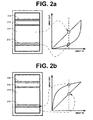
- Figure 2a is an illustration of an exemplary print having impact bands.
- Figure 2b is an illustration of compensating the exemplary print for the impact bands.
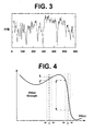
- Figure 3 is an exemplary profile of color variation in a color patch that is printed by a digital printing press.
- Figure 4 is an illustration of dither strength.
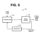
- Figure 5 is an illustration of a hardware implementation of the method of Figure 1 .
- the present invention is embodied in a method for reducing the visibility of banding artifacts in prints produced by a liquid electrophotography print engine.
- the method addresses the symptom of banding artifacts, rather than the cause.
- the method is especially effective for reducing the visibility of the banding artifacts in prints made by digital printing presses and other machines in which the cause of the banding artifacts is difficult to identify or correct.
- the print engine uses multiple colors of ink. For example, a four-ink print engine might print with cyan (C), magenta (M), yellow (Y) and black (K) inks. A seven-ink print engine might also print with light cyan, light magenta, and spot color.
- the print engine is used to print a set of test patterns (110).
- the test patterns may contain, without limitation, constant patches of inks in various ink densities on the same or different sheets, constant patches of ink in the same density at the same spatial locations on a sequence of sheets, density patches of ink on different print media, etc.
- a ramp is an example of a test pattern. In a ramp, ink density gradually changes across the sheet. The ramp is preferably oriented perpendicular to the artifacts. Thus the ramp should change (increase or decrease) in a vertical detection if the artifacts extend in a horizontal direction.
- the set may include different test patterns. One test pattern may be printed per sheet.
- the same test pattern may be printed for each of the color separations.
- a four-ink printer may make at least four prints of the same test pattern.
- lighter ink separations are preferably printed using darker ink, since artifacts printed with the lighter inks (e.g., cyan, yellow) are more difficult to detect.
- Black ink is preferably used instead of the lighter inks.
- the set includes four groups of test patterns.
- the test patterns are large rectangles. Each group corresponds to a different color separation.
- the first, second, third and fourth groups correspond to black, cyan, magenta, and yellow separations, respectively.
- Each group contains different test patterns.
- Black ink used for each separation Thus the different test patterns in the first group are rendered in black ink; the different patterns in the second group are rendered in black ink (instead of cyan ink), the different patterns in the third group are rendered in black ink (instead of magenta ink), and the different patterns in the fourth group are rendered in black ink (instead of yellow ink).
- each group appears to have the same prints, even though they are different.
- the prints of the test patterns will allow banding artifacts in each separation to be identified and modeled.
- Figure 2a shows a simple example of a print 210 of a test pattern.
- a large rectangular patch of a single process color is printed at constant ink density. Because of imperfections in the print engine, this print has horizontal bands 212.
- the background 214 is a constant ink density of the process color, and the band appears as a different shade of that process color.
- the background 214 might be a light gray
- the impact band 212 might be a dark gray or black.
- Figure 3 provides a more realistic example of color variation in a solid color patch that is printed by a digital printing press.
- the graph of Figure 3 represents an average ink density measurement along the artifact direction as a function of perpendicular location.
- AVG denotes the average ink density across the print and across all prints of the same test pattern.
- the bands tend to have a constant location from print to print. Depth or darkness of the bands typically varies from print to print (that is, the banding artifacts vary over time). For example, if one hundred test patterns are printed, the banding artifacts tend to appear at the same location on each print, but the ink density of the artifacts will differ from print to print.
- a banding artifact from a digital printing press is usually stable from print to print; however, its average ink density changes are only partly predictable from print to print.
- Other characteristics of a banding artifact might be partly predictable (i.e., stable and non-random). For example, the change in ink density along the length or width of the banding artifact might be partly predictable. Changes over long time ranges and long print runs (e.g., during warm-up of the printing press) may also be partly predictable. Some or all of these partly predictable characteristics are used (112-116) to reduce the visibility of the banding artifacts in subsequent prints made by the digital printing press.
- Ink density in each print of test patterns is measured (112). Ink density of an entire print may be measured. In the alternative, locations of the artifacts can be identified (e.g., by visual inspection, by computer analysis of the prints), and the ink density of each artifact is measured.
- the prints of the test patterns are scanned by a scanner, whereby a digital image is produced for each print. It is determined (or assumed) that the prints contain rows of banding artifacts. For each row of each digital image, a statistical average of ink density is determined by summing the pixel values in the row, and dividing the sum by the number of pixels in the row.
- the prints of the test patterns are scanned, whereby pixel values of each row are produced. Locations of banding artifacts are determined. It is also determined that the change in ink density along a row is predictable. For each artifact of each digital image, a curve describing the change in ink density along the length of each banding artifact is fitted to the pixel values.
- the locations of the artifacts are identified, and the bias of the artifacts is measured.
- Each artifact is considered a random signal with a non-zero average. This non-zero average is statistically estimated from the set of prints of the same test pattern.
- a densitometer may be used in place of a scanner.
- the densitometer would typically measure a thin strip along a sheet (across the artifacts).
- the various separations may be processed separately such that a measurement is made for each separation.
- the measurements are used to generate parametric artifact models of the artifacts (114).
- One model may be generated for each separation.
- Each model may be represented as the function PR s (x), where x is the location of the artifact and PR s (x) is its amplitude in the s th separation.
- the function PR s (x) may be generated by averaging profiles from the different test patterns.
- the functions PR s (x) will be used as a predictor of banding artifacts in each separation of subsequent prints.
- a function other than PR s (x) may be used.
- a function PR s (x,t) would describe amplitude as a function of location and time.
- a function PR s (x,g) would describe amplitude as a function of location and input gray value or ink load.
- the digital image to be reproduced in the subsequent prints is modified with the parametric artifact model (116).
- the digital image is separated into its separations, and the models are used to modify the tone of the separations at the expected locations of the banding artifacts. Consequently, the print engine will be instructed to print inverses of the artifacts at the artifact locations.
- An inverse would be a lighter color at the location of a darker band, or a darker color at the location of a lighter band.
- Inverses 216 of an artifact are illustrated in Figure 2b .
- the tone of the background should be produced at the artifact location.
- residual error is expected to remain due to variability in the artifact.
- the residual error can be reduced by dithering the banding artifacts.
- the dithering is performed by adding random noise at the locations of the residual bands.
- the function PR s (x+ ⁇ ) may be used instead of PR s (x), where ⁇ is a random number within an appropriate range (e.g. ⁇ 1mm).
- the function PR s (x+ ⁇ ) may add the random noise only where necessary.
- FIG. 4 An illustration of exemplary dither strength is illustrated in Figure 4 .
- the artifacts are characterized by a high gradient in the function PR s (x) Since residual error correlates with the artifacts, a stronger dither is performed at the locations of the artifacts.
- the function PR s (x+ ⁇ ) has larger deviations from PR s (x) near areas where the function PR s (x) has a stronger gradient.
- the modified digital image is sent to the print engine, which makes a set of prints (118). Whereas the prints of the test patterns are used for artifact measurement and modeling, the prints of the modified digital image may be displayed, published, or otherwise distributed.
- the artifacts may repeat predictably across different ink loads and time. If they do, the same profile can be used for the appropriate ink loads and prints in the prints of the digital image.
- profiles of the artifacts can change. For example, the banding artifacts might drift slowly in time, or the banding artifacts might change if a component of the print engine is replaced.
- the modified digital image may be further modified to account for these changes (120). Feedback information may be obtained to determine whether the profiles change over time. Once changes are ascertained, a new the parametric artifact model may be generated, and the digital image may be modified with the new parametric artifact model.
- Changes for drift may be determined by printing test patterns on or in addition to the prints of the modified digital image. These test patterns can then be analyzed for changes in the banding artifacts.
- FIG. 5 illustrates an exemplary hardware implementation 510 of the method just described.
- the hardware implementation 510 includes a controller 512, a detector 514, and a print engine 516.
- a computer is programmed to function as the controller 512, and the detector 514 is a scanner.
- the computer supplies test patterns to the print engine 516.
- the resulting prints are scanned by the scanner, and the resulting digital images are supplied to the computer.
- the computer uses pixel values in the digital images to make measurements of the artifacts; uses the measurements to model the banding artifacts in each separation, uses the models to modify a digital image to be reproduced, and sends the modified digital image to the print engine 516.
- the controller 512 is an ASIC
- the image analyzer 514 is a densitometer.
- the ASIC, the densitometer and the print engine 516 are part of a digital printing press.
- the ASIC instructs the print engine 516 to print a set of test patterns. Strips of these prints are scanned by the densitometer.
- Ink density values are sent by the densitometer to the ASIC.
- the ASIC uses the ink density values to generate a parametric artifact model for each separation.
- An image source (not shown) sends a digital image to the ASIC, which modifies the digital image with the parametric artifact model, and sends the modified digital image to the print engine 516.
- the processor 512 could use a pipeline of lookup tables (LUTs) to modify the digital image.
- LUT lookup table
- One lookup table (LUT) may be used for each separation.
- the table LUT(x+ ⁇ ,g) may be indexed by a randomized location, where ⁇ is randomized for each pixel. Using such an LUT, the pixel value changes randomly along the length of the artifact. Randomized ⁇ s may be used for every pixel in the artifact correction zone, which may cover the entire image or a portion of the image.
- the method is not limited to any particular hardware implementation.
- the parametric artifact models may be applied by means other than lookup tables.
- the measurements may be made by means other than scanners and densitometers.
- the print engine may be a liquid electrophotography engine, a laserjet engine, or any other print engine that produces banding artifacts.
- the processing may be performed entirely by a standalone machine (such as a computer), entirely by a processor in the image analyzer, or it may be distributed among different machines.
- a digital printing press is but one example.
- the present invention may be applied to digital copiers and other machines having liquid electrophotography print engines.
Landscapes
- Engineering & Computer Science (AREA)
- Multimedia (AREA)
- Signal Processing (AREA)
- Quality & Reliability (AREA)
- Ink Jet (AREA)
- Accessory Devices And Overall Control Thereof (AREA)
- Color, Gradation (AREA)
- Facsimile Image Signal Circuits (AREA)
Applications Claiming Priority (3)
| Application Number | Priority Date | Filing Date | Title |
|---|---|---|---|
| US290927 | 1988-12-28 | ||
| US10/290,927 US6682173B1 (en) | 2002-11-08 | 2002-11-08 | Symptomatic reduction of banding artifacts |
| PCT/US2003/035823 WO2004045202A1 (en) | 2002-11-08 | 2003-11-07 | Symptomatic reduction of banding artifacts |
Publications (2)
| Publication Number | Publication Date |
|---|---|
| EP1566053A1 EP1566053A1 (en) | 2005-08-24 |
| EP1566053B1 true EP1566053B1 (en) | 2009-01-07 |
Family
ID=30115358
Family Applications (1)
| Application Number | Title | Priority Date | Filing Date |
|---|---|---|---|
| EP03783289A Expired - Lifetime EP1566053B1 (en) | 2002-11-08 | 2003-11-07 | Symptomatic reduction of banding artifacts |
Country Status (6)
| Country | Link |
|---|---|
| US (1) | US6682173B1 (enExample) |
| EP (1) | EP1566053B1 (enExample) |
| JP (1) | JP2006509647A (enExample) |
| AU (1) | AU2003290707A1 (enExample) |
| DE (1) | DE60325767D1 (enExample) |
| WO (1) | WO2004045202A1 (enExample) |
Families Citing this family (6)
| Publication number | Priority date | Publication date | Assignee | Title |
|---|---|---|---|---|
| US8614830B2 (en) * | 2004-09-27 | 2013-12-24 | Hewlett-Packard Development Company, L.P. | Pixel exposure as a function of subpixels |
| US8120816B2 (en) * | 2005-06-30 | 2012-02-21 | Xerox Corporation | Automated image quality diagnostics system |
| US7431522B2 (en) * | 2006-01-17 | 2008-10-07 | Lexmark International, Inc | Method for reducing banding in an imaging apparatus |
| US8351080B2 (en) * | 2009-09-08 | 2013-01-08 | Xerox Corporation | Least squares based coherent multipage analysis of printer banding for diagnostics and compensation |
| US8649068B2 (en) * | 2011-12-22 | 2014-02-11 | Xerox Corporation | Process for creating facet-specific electronic banding compensation profiles for raster output scanners |
| US20190114517A1 (en) * | 2017-10-17 | 2019-04-18 | Xerox Corporation | Mitigation of print banding using a single user-controllable parameter |
Family Cites Families (10)
| Publication number | Priority date | Publication date | Assignee | Title |
|---|---|---|---|---|
| US5182990A (en) * | 1991-01-09 | 1993-02-02 | Presstek, Inc. | Method of reducing printing artifacts |
| US5592592A (en) * | 1994-07-01 | 1997-01-07 | Seiko Epson Corporation | Method and apparatus for minimizing artifacts in images produced by error diffusion halftoning utilizing ink reduction processing |
| US5992962A (en) * | 1994-12-22 | 1999-11-30 | Hewlett-Packard Company | Print masks for inkjet printers |
| US5703695A (en) * | 1995-03-20 | 1997-12-30 | Nguyen; Hugh P. | Multi-dot dither matrix generation |
| US5956469A (en) * | 1995-06-19 | 1999-09-21 | Eastman Kodak Company | Selecting a calibration function for a digital printer which minimizes an error criterion |
| JP3633764B2 (ja) * | 1997-11-14 | 2005-03-30 | 株式会社リコー | バンディングの定量化方法 |
| US6137592A (en) * | 1998-01-20 | 2000-10-24 | Hewlett-Packard Company | Method for adjusting drive roller linefeed distance |
| US6164750A (en) * | 1998-03-04 | 2000-12-26 | Hewlett-Packard Company | Automated test pattern technique using accelerated sequence of color printing and optical scanning |
| US6364549B1 (en) * | 2000-04-27 | 2002-04-02 | Hewlett-Packard Company | Calibration of a media advanced system |
| US7417768B1 (en) * | 2000-10-13 | 2008-08-26 | Hewlett-Packard Development Company, L.P. | Apparatus and method for mitigating colorant-deposition errors in incremental printing |
-
2002
- 2002-11-08 US US10/290,927 patent/US6682173B1/en not_active Expired - Lifetime
-
2003
- 2003-11-07 JP JP2004552006A patent/JP2006509647A/ja active Pending
- 2003-11-07 DE DE60325767T patent/DE60325767D1/de not_active Expired - Lifetime
- 2003-11-07 AU AU2003290707A patent/AU2003290707A1/en not_active Abandoned
- 2003-11-07 EP EP03783289A patent/EP1566053B1/en not_active Expired - Lifetime
- 2003-11-07 WO PCT/US2003/035823 patent/WO2004045202A1/en not_active Ceased
Also Published As
| Publication number | Publication date |
|---|---|
| EP1566053A1 (en) | 2005-08-24 |
| US6682173B1 (en) | 2004-01-27 |
| DE60325767D1 (de) | 2009-02-26 |
| WO2004045202A1 (en) | 2004-05-27 |
| AU2003290707A1 (en) | 2004-06-03 |
| JP2006509647A (ja) | 2006-03-23 |
Similar Documents
| Publication | Publication Date | Title |
|---|---|---|
| US5649073A (en) | Automatic calibration of halftones | |
| US7095531B2 (en) | Systems and methods for compensating for streaks in images | |
| US10880453B2 (en) | Image processing device and method, program, recording medium, and inkjet printing system | |
| US7206099B2 (en) | Media/screen look-up-table for color consistency | |
| JP4511497B2 (ja) | 画像形成装置較正に用いるために走査パッチを処理する方法及びシステム | |
| JP6409308B2 (ja) | 画像処理装置、画像処理方法、プログラム、及び、画像処理システム | |
| US20120133991A1 (en) | Halftone independent correction of spatial non-uniformities | |
| US7742713B2 (en) | Measurement of engine response curve in the presence of process direction noise | |
| US9774763B2 (en) | Method for controlling a printing process | |
| US6304278B1 (en) | Achieving system stability in anamorphic printer defect pre-compensation | |
| US8339690B2 (en) | Halftone printing with different screens | |
| EP1566053B1 (en) | Symptomatic reduction of banding artifacts | |
| US8368955B2 (en) | Method for assessing synchronized print defects | |
| US7280259B2 (en) | Method for printing a color proof using a spatial filter | |
| EP1014296A2 (en) | Adjusting halftone patterns to maintain print quality | |
| US7898695B1 (en) | Method of compensating for electronic printhead skew and bow correction in an imaging machine to reduce print artifacts | |
| EP0248616A2 (en) | Picture printing apparatus | |
| WO2016031632A1 (ja) | 印刷システム及び管理装置並びに管理方法 | |
| US7453587B2 (en) | Method for removing streaks from a scanned image | |
| JPH08289149A (ja) | 画像記録装置およびその方法 | |
| US12240254B2 (en) | Automatic tuning compensation mechanism | |
| US12240252B2 (en) | Automatic tuning compensation mechanism | |
| EP4420882B1 (en) | Automatic tuning compensation mechanism | |
| US12192433B2 (en) | Image forming apparatus, control method of image forming apparatus, and storage medium | |
| US20070133018A1 (en) | Graphics color proofing system |
Legal Events
| Date | Code | Title | Description |
|---|---|---|---|
| PUAI | Public reference made under article 153(3) epc to a published international application that has entered the european phase |
Free format text: ORIGINAL CODE: 0009012 |
|
| 17P | Request for examination filed |
Effective date: 20050509 |
|
| AK | Designated contracting states |
Kind code of ref document: A1 Designated state(s): AT BE BG CH CY CZ DE DK EE ES FI FR GB GR HU IE IT LI LU MC NL PT RO SE SI SK TR |
|
| AX | Request for extension of the european patent |
Extension state: AL LT LV MK |
|
| DAX | Request for extension of the european patent (deleted) | ||
| RBV | Designated contracting states (corrected) |
Designated state(s): DE FR GB |
|
| RIN1 | Information on inventor provided before grant (corrected) |
Inventor name: SHAW, RODNEY Inventor name: SHAKED, DORON Inventor name: GILA, OMER |
|
| GRAP | Despatch of communication of intention to grant a patent |
Free format text: ORIGINAL CODE: EPIDOSNIGR1 |
|
| GRAS | Grant fee paid |
Free format text: ORIGINAL CODE: EPIDOSNIGR3 |
|
| GRAA | (expected) grant |
Free format text: ORIGINAL CODE: 0009210 |
|
| AK | Designated contracting states |
Kind code of ref document: B1 Designated state(s): DE FR GB |
|
| REG | Reference to a national code |
Ref country code: GB Ref legal event code: FG4D |
|
| REF | Corresponds to: |
Ref document number: 60325767 Country of ref document: DE Date of ref document: 20090226 Kind code of ref document: P |
|
| PLBE | No opposition filed within time limit |
Free format text: ORIGINAL CODE: 0009261 |
|
| STAA | Information on the status of an ep patent application or granted ep patent |
Free format text: STATUS: NO OPPOSITION FILED WITHIN TIME LIMIT |
|
| 26N | No opposition filed |
Effective date: 20091008 |
|
| PGFP | Annual fee paid to national office [announced via postgrant information from national office to epo] |
Ref country code: DE Payment date: 20131022 Year of fee payment: 11 Ref country code: FR Payment date: 20131121 Year of fee payment: 11 Ref country code: GB Payment date: 20131025 Year of fee payment: 11 |
|
| REG | Reference to a national code |
Ref country code: DE Ref legal event code: R119 Ref document number: 60325767 Country of ref document: DE |
|
| GBPC | Gb: european patent ceased through non-payment of renewal fee |
Effective date: 20141107 |
|
| REG | Reference to a national code |
Ref country code: FR Ref legal event code: ST Effective date: 20150731 |
|
| PG25 | Lapsed in a contracting state [announced via postgrant information from national office to epo] |
Ref country code: DE Free format text: LAPSE BECAUSE OF NON-PAYMENT OF DUE FEES Effective date: 20150602 Ref country code: GB Free format text: LAPSE BECAUSE OF NON-PAYMENT OF DUE FEES Effective date: 20141107 |
|
| PG25 | Lapsed in a contracting state [announced via postgrant information from national office to epo] |
Ref country code: FR Free format text: LAPSE BECAUSE OF NON-PAYMENT OF DUE FEES Effective date: 20141201 |